EP4438227A1 - Machine tool and machine tool handling method - Google Patents
Machine tool and machine tool handling method Download PDFInfo
- Publication number
- EP4438227A1 EP4438227A1 EP21969026.0A EP21969026A EP4438227A1 EP 4438227 A1 EP4438227 A1 EP 4438227A1 EP 21969026 A EP21969026 A EP 21969026A EP 4438227 A1 EP4438227 A1 EP 4438227A1
- Authority
- EP
- European Patent Office
- Prior art keywords
- cover
- machine tool
- wall
- mover
- support member
- Prior art date
- Legal status (The legal status is an assumption and is not a legal conclusion. Google has not performed a legal analysis and makes no representation as to the accuracy of the status listed.)
- Pending
Links
Images











Classifications
-
- B—PERFORMING OPERATIONS; TRANSPORTING
- B23—MACHINE TOOLS; METAL-WORKING NOT OTHERWISE PROVIDED FOR
- B23Q—DETAILS, COMPONENTS, OR ACCESSORIES FOR MACHINE TOOLS, e.g. ARRANGEMENTS FOR COPYING OR CONTROLLING; MACHINE TOOLS IN GENERAL CHARACTERISED BY THE CONSTRUCTION OF PARTICULAR DETAILS OR COMPONENTS; COMBINATIONS OR ASSOCIATIONS OF METAL-WORKING MACHINES, NOT DIRECTED TO A PARTICULAR RESULT
- B23Q11/00—Accessories fitted to machine tools for keeping tools or parts of the machine in good working condition or for cooling work; Safety devices specially combined with or arranged in, or specially adapted for use in connection with, machine tools
- B23Q11/08—Protective coverings for parts of machine tools; Splash guards
- B23Q11/0891—Protective coverings for parts of machine tools; Splash guards arranged between the working area and the operator
-
- B—PERFORMING OPERATIONS; TRANSPORTING
- B23—MACHINE TOOLS; METAL-WORKING NOT OTHERWISE PROVIDED FOR
- B23Q—DETAILS, COMPONENTS, OR ACCESSORIES FOR MACHINE TOOLS, e.g. ARRANGEMENTS FOR COPYING OR CONTROLLING; MACHINE TOOLS IN GENERAL CHARACTERISED BY THE CONSTRUCTION OF PARTICULAR DETAILS OR COMPONENTS; COMBINATIONS OR ASSOCIATIONS OF METAL-WORKING MACHINES, NOT DIRECTED TO A PARTICULAR RESULT
- B23Q1/00—Members which are comprised in the general build-up of a form of machine, particularly relatively large fixed members
- B23Q1/25—Movable or adjustable work or tool supports
- B23Q1/44—Movable or adjustable work or tool supports using particular mechanisms
- B23Q1/50—Movable or adjustable work or tool supports using particular mechanisms with rotating pairs only, the rotating pairs being the first two elements of the mechanism
- B23Q1/52—Movable or adjustable work or tool supports using particular mechanisms with rotating pairs only, the rotating pairs being the first two elements of the mechanism a single rotating pair
- B23Q1/525—Movable or adjustable work or tool supports using particular mechanisms with rotating pairs only, the rotating pairs being the first two elements of the mechanism a single rotating pair which is parallel to the working surface
Definitions
- a machine tool provided with a cover is known.
- a machine tool includes a table, a tool support, a mover, a first wall, a first cover, and a first support.
- the table is configured to support a workpiece and move in a first direction and a second direction opposite to the first direction.
- the tool support is configured to support a tool for machining the workpiece.
- the mover is configured to move the table.
- the first wall is provided further in the first direction than the table and having a first opening.
- the first cover protrudes further in the first direction than the first wall through the first opening.
- the first support member supports the first cover such that the first cover is tiltable to decrease an amount of protrusion of the first cover relative to the first wall.
- the method also includes a step of installing the transported machine tool at an installment site.
- the method also includes a tilting step of causing the first cover to tilt from the second position to the first position to increase the amount of protrusion of the first cover in the first direction relative to the first wall.
- the method also includes a step of fixing the first cover to the first position.
- the present invention provides a machine the tool That can be compact in size during transportation, and provides a method of handling a machine tool such that the method makes the machine tool compact in size during transportation.
- the present invention contributes to decarbonization and SDGs.
- the terms “upward”, “up”, and “above” each refer to a direction oriented upward, from a lower portion
- the terms “downward”, “down”, and “below” each refer to a direction oriented downward, from an upper position.
- the term “side” refers to a lateral direction (in other words, a direction other than “upward”, “up”, “above”, “downward”, “down”, and “below”).
- FIGs. 1 and 2 each are a cross-sectional view of the machine tool 1A according to the first embodiment, schematically illustrating the machine tool 1A. It is to be noted that FIG. 1 illustrates a state in which a first cover 6 is positioned at a first position P1, and FIG. 2 illustrates a state in which the first cover 6 is positioned at a second position P2.
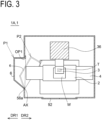
- FIG. 3 is a cross-sectional view of the machine tool 1A according to a modification of the first embodiment, schematically illustrating the machine tool 1A.
- the machine tool 1A includes a table 2, a tool support 3, a mover 4, a first wall 51a, the first cover 6, and a first support member 56a.
- the tool support 3 supports a tool T, which is for machining the workpiece W.
- the tool support 3 is movable in, for example, a direction parallel to a vertical direction.
- the mover 4 moves the table 2.
- the mover 4 is capable of moving the table 2 in the first direction DR1 , and is capable of moving the table 2 in the second direction DR2 .
- the first cover 6 protrudes further in the first direction DR1 than the first wall 51a through the first opening OP1.
- the first cover 6 prevents scattering of chips, coolant, and other substances in the first direction DR1 beyond the first cover 6.
- the first cover 6 also protects the table 2 and/or the mover 4 on one side (more specifically, on the first direction DR1 side). As described later, the first cover 6 is tiltable and, as such, can be referred to as "first tiltable cover”.
- the first support member 56a supports the first cover 6 such that the first cover 6 is tiltable to decrease the amount of protrusion of the first cover 6 (the amount of protrusion in the first direction DR1 ) relative to the first wall 51a.
- the first support member 56a supports the first cover 6 while the first cover 6 is tilting from the first position P1 to the second position P2 (see FIG. 2 ).
- the amount of protrusion by which the first cover 6 protrudes in the first direction DR1 relative to the first wall 51a is defined as second amount of protrusion A2 (see FIG. 2 ).
- the amount of protrusion by which the first cover 6 protrudes in the first direction DR1 relative to the first wall 51a is defined as first amount of protrusion A1 (see FIG. 1 ).
- the second amount of protrusion A2 is smaller than the first amount of protrusion A1.
- the first cover 6 can be caused to tilt in a direction in which the amount of protrusion of the first cover 6 is decreased relative to the first wall 51a.
- the machine tool 1A as a whole is made compact in size (more specifically, size of the machine tool 1A during transportation). This configuration enables the machine tool 1A to be transported on general-purpose containers or smaller size transportation vehicles, and thus contributes to decarbonization and SDGs.
- the first cover 6 is supported by the first support member 56a in a state in which the amount of protrusion of the first cover 6 relative to the first wall 51a is decreased.
- the first support member 56a serves as a fulcrum on which the first cover 6 tilts in the direction to increase the amount of protrusion.
- the first cover 6 is changeable in position from the second position P2 (in other words, from the housing position) to the first position P1 (in other words, to the closed position).
- the first cover 6 protrudes further in the first direction DR1 than the first wall 51a. This makes the machine tool 1A larger in inner region.
- the machine tool 1A can be compact in size during transportation without compromising specifications of the machine tool 1A (such as the size of the table 2 and the movement stroke of the table 2 in a direction parallel to the first direction DR1 ).
- the first embodiment enables the machine tool 1A to be compact in size during transportation, ensures easiness in the assembly of the machine tool 1A, and enables specifications of the machine tool 1A to be maintained.
- the first cover 6 has a tilting axis AX.
- the tilting axis AX is parallel to a horizontal direction, and is provided at a lower end portion of the first cover 6.
- the tilting axis AX of the first cover 6 will not be limited to being parallel to the horizontal direction.
- the tilting axis AX of the first cover 6 also will not be limited to being provided at the lower end portion of the first cover 6.
- the tilting axis AX of the first cover 6 may be parallel to the vertical direction. In other words, the first cover 6 may be tiltable about an axis parallel to the vertical direction.
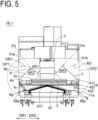
- FIGs. 4 and 5 each are a front view of the machine tool 1B according to the second embodiment, schematically illustrating the machine tool 1B.
- FIG. 4 illustrates a state in which the first cover 6 is positioned at the first position P1
- FIG. 5 illustrates a state in which the first cover 6 is positioned at the second position P2.
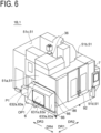
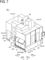
- FIGs. 6 and 7 each are a perspective view of the machine tool 1B according to the second embodiment, schematically illustrating the machine tool 1B.
- FIG. 6 illustrates a state in which the first cover 6 is positioned at the first position P1
- FIG. 7 illustrates a state in which the first cover 6 is positioned at the second position P2.
- FIG. 6 illustrates a state in which the first cover 6 is positioned at the first position P1
- FIG. 7 illustrates a state in which the first cover 6 is positioned at the second position P2.
- FIGs. 11 and 12 each are a front view of the machine tool 1B according to the second embodiment, schematically illustrating the machine tool 1B.
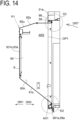
- FIGs. 13 and 14 each are a cross-sectional view of the first support member 56a and the first cover 6, schematically illustrating a state in which the first support member 56a supports the first cover 6.
- FIG. 15 is an enlarged view of a part indicated by circle D1 in FIG. 13 .
- FIG. 16 is an enlarged view of a part indicated by circle D2 in FIG. 14 .
- FIG. 17 is an enlarged view of a part indicated by circle D3 in FIG. 14 .
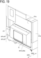
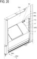
- FIGs. 18 to 20 each are a perspective view of the machine tool 1B, schematically illustrating some parts of the machine tool 1B. It is to be noted that in FIGs. 4 , 5 , 11 , and 12 , a part of the machine tool 1B (the part surrounded by a single-dashed elongated circle) is cut away to show an internal configuration of the machine
- the second embodiment provides effects similar to the effects of the first embodiment.
- the first cover 6 is changeable in position between the first position P1 (see FIG. 6 ) and the second position P2 (see FIG. 7 ).
- the first position P1 the first opening OP1 of the first wall 51a is closed.
- the second position P2 the amount of protrusion of the first cover 6 in the first direction DR1 relative to the first wall 51a is decreased.
- a part of the first opening OP1 of the first wall 51a is open, instead of being closed by the first cover 6.
- the first cover 6 when the first cover 6 is positioned at the second position P2, the first cover 6 is entirely housed in the second direction DR2 relative to the first wall 51a.
- one part of the first cover 6 when the first cover 6 is positioned at the second position P2, one part of the first cover 6 may protrude further in the first direction DR1 than the first wall 51a, and the other part of the first cover 6 may be housed in the second direction DR2 relative to the first wall 51a.
- the second amount of protrusion A2 may be a value larger than zero and smaller than the first amount of protrusion A1.
- the first cover 6 is tiltable from the first position P1 toward the second position P2 to cross a workpiece machining region AR1. More specifically, while the first cover 6 is tilting from the first position P1 toward the second position P2, the first cover 6 crosses the workpiece machining region AR1 of the machine tool 1B.
- the workpiece machining region AR1 becomes a temporary unused region during transportation of the machine tool.
- the workpiece machining region AR1 can be utilized as a unused region in which the first cover 6 tilts to the second position P2.
- the "workpiece machining region AR1" refers to a region that is a part of the region immediately above the table 2 and that is reachable by a tool supported by the tool support 3. It is also to be noted that in a case where the table 2 is movable in a horizontal direction, the region immediately above the table 2 refers to a region immediately above the entire movable range of the table 2.
- the table 2 is movable in the first direction DR1 and the second direction DR2 , which is opposite to the first direction DR1 . Additionally, the table 2 may be movable in a direction different from a direction parallel to the first direction DR1 . In the example illustrated in FIG. 8 , the table 2 is movable in a third direction DR3 , which is perpendicular to the first direction DR1 , and in a fourth direction DR4, which is opposite to the third direction DR3. It is to be noted that in the example illustrated in FIG. 8 , in the first direction DR1 , the second direction DR2, the third direction DR3 , and the fourth direction DR4 are parallel to a horizontal direction.
- the tool support 3 includes a tool support member 31 and a support member mover 35.
- the tool support member 31 supports a tool.
- the support member mover 35 moves the tool support member 31.
- the tool support member 31 is movable in directions parallel to the vertical direction (more specifically, in a vertically upward direction DR5 and a vertically downward direction DR6).
- the support member mover 35 moves the tool support member 31 in a direction parallel to the vertical direction.
- the support member mover 35 includes a linear guide 37 and a drive 38.
- the linear guide 37 guides the tool support member 31 to move in the directions parallel to the vertical direction.
- the drive 38 applies moving force to the tool support member 31.
- the linear guide 37 is provided at a column 36.
- the column 36 is fixed to a base 91 of the machine tool 1B, and is provided further in the third direction DR3 than the table 2.
- the mover 4, which moves the table 2 includes a table support member 41 and a first drive 43.
- the table support member 41 supports the table 2 in a manner in which the table 2 is movable in a direction parallel to the first direction DR1 .
- the first drive 43 (for example, a motor) applies moving force to the table 2 in the direction parallel to the first direction DR1 .
- the table support member 41 includes a first linear guide 42 (such as a first track).
- the first linear guide 42 guides the table 2 to move in the direction parallel to the first direction DR1 .
- the table 2 is linearly movable along the first linear guide 42.
- the first drive 43 includes, for example, a ball screw 431 and a motor 432.
- the motor 432 drives the ball screw 431 into rotation.
- the first drive 43 may include a linear motor.
- the mover 4, which moves the table 2 may include a first expandable-contractable cover 44a.
- the first expandable-contractable cover 44a is provided on the first direction DR1 side relative to the table 2 to prevent foreign matter (such as workpiece chips, coolant, and other substances) from entering the space between the table 2 and the table support member 41.
- the first expandable-contractable cover 44a expands as the table 2 moves in the second direction DR2 , and contracts as the table 2 moves in the first direction DR1 .
- one end portion of the first expandable-contractable cover 44a may be mounted on the table 2
- another end portion of the first expandable-contractable cover 44a may be mounted on the table support member 41 or first aid tracks 45a.
- the first aid tracks 45a are fixed to the table support member 41.
- the mover 4, which moves the table 2 includes the first aid tracks 45a.
- the first aid tracks 45a aid the first expandable-contractable cover 44a in expanding and contracting in the direction parallel to the first direction DR1 .
- the first expandable-contractable cover 44a smoothly expand and contract along the first aid tracks 45a.
- the mover 4 which moves the table 2 may include a second expandable-contractable cover 44b.
- the second expandable-contractable cover 44b is provided on the second direction DR2 side relative to the table 2 to prevent foreign matter (such as workpiece chips, coolant, and other substances) from entering the space between the table 2 and the table support member 41.
- the second expandable-contractable cover 44b expands as the table 2 moves in the first direction DR1 , and contracts as the table 2 moves in the second direction DR2.
- one end portion of the second expandable-contractable cover 44b may be mounted on the table 2
- another end portion of the second expandable-contractable cover 44b may be mounted on the table support member 41 or second aid tracks 45b.
- the second aid tracks 45b are fixed to the table support member 41.
- the mover 4 which moves the table 2 may include a third expandable-contractable cover 49a and/or a fourth expandable-contractable cover 49b.
- the fourth expandable-contractable cover 49b is provided on the fourth direction DR4 side relative to the table support member 41 to prevent foreign matter (such as workpiece chips, coolant, and other substances) from entering the space between the table support member 41 and the second table support member 46.
- the fourth expandable-contractable cover 49b expands as the table 2 and the table support member 41 move in the third direction DR3, and contracts as the table 2 and the table support member 41 move in the fourth direction DR4.
- the first cover 6 when the first cover 6 is positioned at the second position P2 (in other words, at the housing position), the first cover 6 is partially provided immediately above the table 2 and the mover 4 (for example, the first linear guide 42, which guides the table 2 to move, the ball screw 431, or other elements).
- the mover 4 for example, the first linear guide 42, which guides the table 2 to move, the ball screw 431, or other elements.
- at least a part of the workpiece machining region AR1, which exists immediately above the table 2 and the mover 4 can be utilized to partially or entirely house the first cover 6 further in the second direction DR2 than the first wall 51a.
- the first cover 6 positioned at the second position P2 contains at least one of a part of the mover 4 and a part of the table 2. Specifically, when the first cover 6 is positioned at the second position P2, at least one of a part 4p of the mover 4 and a part 2p of the table 2 is provided in an inner region AR2 of the first cover 6. In this case, when the first cover 6 is positioned at the second position P2, the inner region AR2 of the first cover 6 is effectively utilized.
- the first cover 6 positioned at the second position P2 contains both the part of the mover 4 and the part of the table 2.
- the first cover 6 positioned at the second position P2 may contain one of the part of the mover 4 and the part of the table 2.
- the first cover 6 While the first cover 6 is tilting from the first position P1 to the second position P2, it is possible for the first cover 6 to interfere with a part of the mover 4.
- the part of the mover 4 that the first cover 6 may possibly interfere with is configured to be removable from a rest part of the mover 4.
- a part of the mover 4 (for example, at least a part of the first expandable-contractable cover 44a and/or at least a part of the first aid tracks 45a) is removed from the rest part, 4r, of the mover 4.
- the first cover 6 is caused to tilt from the first position P1 to the second position P2 in a state in which the part of the mover 4 is removed from the rest part of the mover 4.
- the removed part, 4s, of the mover 4 is caused to be mounted on the rest part 4r of the mover 4 before the machine tool 1B is used. More specifically, in a state in which the first cover 6 is positioned at the first position P 1, the part 4s of the mover 4 is provided in the inner region AR2 of the first cover 6.
- a part of the table 2 that has moved furthest in the first direction DR1 may be providable in the inner region AR2 of the first cover 6 positioned at the first position P1.
- the inner region AR2 can be used to expand the movable range of the table 2 in the direction parallel to the first direction DR1 .
- a nozzle 93 may be provided in the inner region AR2 of the first cover 6. Through the nozzle 93, cleaning solution to wash away coolant attached to the first cover 6 is ejected.
- the first support member 56a supports the lower end portion, 6g, of the first cover 6 such that the first cover 6 is tiltable.
- the amount of movement of the lower end portion 6g of the first cover 6 is smaller than the amount of movement of an upper end portion 6e of the first cover 6.
- the first cover 6 can be caused to tilt more easily in a manner to avoid interference between the lower end portion 6g of the first cover 6 and the table 2 and the mover 4.
- the workpiece machining region AR1 exists immediately above the table 2 and the mover 4 of the machine tool 1B.
- adverse effects caused by the relatively large amount of movement of the upper end portion 6e of the first cover 6 are not actualized.
- the upper end portion 6e of the first cover 6 can be moved spaciously.
- the first support member 56a supports the first cover 6 (more specifically, the lower end portion 6g of the first cover 6) such that the first cover 6 is tiltable about a first axis AX1.
- An example of the first support member 56a is a pin member 561a.
- the pin member 561a supports the first cover 6 such that the first cover 6 is tiltable.
- the pin member 561a defines the first axis AX1, which is a tilting axis of the first cover 6.
- the first axis AX1 is an axis parallel to a horizontal direction.
- the lower end portion 6g of the first cover 6 may include a first hook 60b.
- the first hook 60b is meshable and de-meshable with and from the pin member 561a.
- the first cover 6 can be easily mounted, easily removed, or easily replaced.
- the first hook 60b also permits the first cover 6 to tilt about the pin member 561a.
- the first hook 60b makes the first cover 6 easily attachable and detachable to and from the pin member 561a without blocking the tilting of the first cover 6 about the pin member 561a.
- the lower end portion 6g of the first cover 6 can be lifted upward (for example, diagonally upward) to remove the first cover 6 from the pin member 561a. It is to be noted that since weight is acting on the first cover 6, the first cover 6 does not come off from the pin member 561a unless the first cover 6 is lifted upward.
- the machine tool 1B may include a lower fluid leakage guard 57.
- the lower fluid leakage guard 57 is provided at the lower end portion 6g of the first cover 6.
- the lower fluid leakage guard 57 prevents a leakage of coolant to outside the machine tool through the gap between the lower end portion 6g of the first cover 6 and the first wall 51a.
- the lower fluid leakage guard 57 is attachable and detachable to and from the lower end portion 6g of the first cover 6. More specifically, the lower fluid leakage guard 57 is attached to the lower end portion 6g of the first cover 6 after the first cover 6 has tilted from the second position P2 (in other words, from the housing position) to the first position P1 (in other words, to the closed position to close the first opening OP1).
- the machine tool 1B may include an upper fluid leakage guard 58.
- the upper fluid leakage guard 58 is provided at the upper end portion 6e of the first cover 6.
- the upper fluid leakage guard 58 prevents a leakage of coolant to outside the machine tool through the gap between the upper end portion 6e of the first cover 6 and the first wall 51a.
- the upper fluid leakage guard 58 is fixed to the upper end portion 6e of the first cover 6. In other words, when the first cover 6 tilts relative to the first support member 56a, the upper fluid leakage guard 58 tilts together with the first cover 6. As exemplified in FIG. 13 , when the first cover 6 is positioned at the second position P2, the upper fluid leakage guard 58 is located away from the first wall 51a. As exemplified in FIG. 14 , when the first cover 6 is positioned at the first position P1, the upper fluid leakage guard 58 is in contact with the first wall 51a.
- the first cover 6 includes a hollow protrusion 65 and a stopper 66.
- the protrusion 65 protrudes in the first direction DR1 through the first opening OP1 of the first wall 51a.
- a tilting direction oriented from the second position P2 toward the first position P1 is defined as first tilting direction DR7.
- the stopper 66 prevents the first cover 6 from tilting in the first tilting direction DR7 past the first position P1. In other words, the stopper 66 defines a tilting limitation position for the tilting of the first cover 6 in the first tilting direction DR7.
- the upper fluid leakage guard 58 serves as a part of the stopper 66.
- the upper fluid leakage guard 58 serves as one member that defines the tilting limitation position for the tilting of the first cover 6 in the first tilting direction DR7.
- the first cover 6 has an outer surface 60u and an inner surface 60n.
- the outer surface 60u is exposed to outside the machine tool.
- the inner surface 60n defines the inner region AR2 of the first cover 6.
- the first cover 6 (more specifically, the outer surface 60u of the first cover 6) has a bottom surface 61s, an upper surface 62s, and a first end surface 631s, which is the first direction DR1 side face.
- the first end surface 631s is a part of a side surface 63s of the first cover 6.
- the side surface 63s of the first cover 6 may have a surface 632s and surface 633s, in addition to the first end surface 631s.
- the surface 632s is the third direction DR3 side face.
- the surface 633s is the fourth direction DR4 side face, which is opposite to the third direction DR3 side face.
- a height of a position of the bottom surface 61s of the first cover 6 positioned at the first position P1 increases in the first direction DR1 .
- the amount of protrusion of the first cover 6 in the first direction DR1 relative to the first wall 51a can be easily decreased.
- the first cover 6 is moved from the first position P1 to the second position P2 (see FIG. 13 )
- causing the first cover 6 to tilt by an angle smaller than 90 degrees about the first axis AX1 suffices (more specifically, by an angle smaller than 75 degrees or an angle smaller than 60 degrees).
- the first cover 6 is caused to tilt by an angle smaller than 90 degrees from the first position P1 toward the second position P2.
- coolant that has reached the first cover 6 can be guided in the second direction DR2 along a bottom wall 61 of the first cover 6 (more specifically, an inner surface 61n of the bottom wall 61), as exemplified in FIG. 16 (see broken-line arrow B4).
- coolant scattering toward the first cover 6 can be collected using the inclination of the bottom wall 61 of the first cover 6.
- the first cover 6 can be easily housed, ensuring that coolant can be easily collected.
- the first cover 6 includes, as its component, a plurality of plate members (for example, a plurality of metal plates). In other words, a plurality of plate members are connected together to form the first cover 6.
- the first cover 6 includes a fixation member 67.
- the fixation member 67 fixes the first cover 6 to the second position P2.
- the machine tool 1B can be transported in a state in which the first cover 6 is fixed to the second position P2. In this case, the first cover 6 is prevented from rattling during transportation of the machine tool 1B.
- the fixation member 67 in a state in which the first cover 6 is positioned at the second position P2, the fixation member 67 is provided at a position where the fixation member 67 is accessible by a user through the first opening OP1 when the user is positioned further in the first direction DR 1 than the first wall 51a (in other words, a position where the fixation member 67 is within reach of a hand of a user positioned outside the machine tool 1B).
- the user is able to fix the fixation member 67 to a structure member 11a of the machine tool 1B without entering the machine tool 1B.
- the user is able to release the fixing of the fixation member 67 to the structure member 11a without entering the machine tool 1B.
- the fixation member 67 or a fixture member fixing the fixation member 67 to the structure member 11a is preferably visually recognizable through the first opening OP1 from a position further in the first direction DR 1 than the first wall 51a.
- the user is able to more easily fix the fixation member 67 or release the fixing of the fixation member 67 without entering the machine tool 1B.
- the fixation member 67 is fixed to the structure member 11a via a fixture member (for example, via a bracket 82a and a bolt 81a).
- the fixation member 67 has first holes 67h.
- the first holes 67h are each capable of receiving a connection member such as the bolt 81a.
- the machine tool 1B includes a plurality of walls 51.
- the plurality of walls 51 include the first wall 51a, which is provided on the first direction DR1 side of the machine tool 1B; and the second wall 51b, which is provided at the second direction DR2 side of the machine tool 1B.
- the plurality of walls 51 may include a third wall 51c and a fourth wall 51d.
- the third wall 51c is provided on the third direction DR3 side of the machine tool 1B.
- the fourth wall 51d is provided on the fourth direction DR4 side of the machine tool 1B.
- Each of the first wall 51a, the second wall 51b, the third wall 51c, and the fourth wall 51d may be made up of a plurality of members.
- the first wall 51a may include a plurality of plate members or a plurality of panels.
- each of the second wall 51b, the third wall 51c, and the fourth wall 51d may include a plurality of plate members or a plurality of panels.
- the machine tool 1B includes a plurality of connection members 86 (for example, a plurality of bolts).
- the plurality of connection members 86 fix the first cover 6 positioned at the first position P1 to the first wall 51a.
- the first wall 51a includes a plurality of second holes 51h.
- the plurality of second holes 51h respectively receive the plurality of connection members 86.
- some of the plurality of second holes 51h are provided further in the third direction DR3 than the first opening OP1, and other of the plurality of second holes 51h are provided further in the fourth direction DR4 than the first opening OP1.
- the fourth wall 51d supports an openable-closable door 92. It is to be noted that in a case where the side on which the door 92 is provided is defined as front surface, the fourth wall 51d may be referred to as front wall. It is also to be noted that in a case where in plan view, the direction from the table 2 toward the column 36, which movably supports the tool support member 31, is defined as rearward, the third wall 51c may be referred to as rear wall. In the example illustrated in FIG. 7 , the first cover 6 is provided at the first wall 51a, which is different from the rear wall.
- the machine tool 1B has at least four walls (the first wall 51a, the second wall 51b, the third wall 51c, and the fourth wall 51d).
- the machine tool 1B may have five or more walls.
- the machine tool 1B includes (1) the second wall 51b, which has a second opening OP2 and is provided further in the second direction DR2 than the table 2, (2) the second cover 7, which protrudes further in the second direction DR2 than the second wall 51b through the second opening OP2, and (3) a second support member 56b, which supports the second cover 7 such that the second cover 7 is tiltable to decrease the amount of protrusion of the second cover 7 relative to the second wall 51b.
- the position of the second cover 7 is changeable between a third position P3 and a fourth position P4. At the third position P3, the second cover 7 closes the second opening OP2 of the second wall 51b.
- the fourth position P4 the amount of protrusion of the second cover 7 in the second direction DR2 relative to the second wall 51b is decreased.
- the machine tool 1B includes the second cover 7 in addition to the first cover 6, which is tiltable in a direction toward the table 2.
- the second cover 7 is tiltable in the direction toward the table 2.
- the machine tool 1B can be more compact in size during transportation of the machine tool 1B.
- the second cover 7 is tiltable to cross the workpiece machining region AR1 from the third position P3 toward the fourth position P4 (see broken-line arrow B2). In this case, it is not necessary to provide a dedicated space or a dedicated movement passage for the tilting of the second cover 7.
- the second support member 56b supports a lower end portion 7g of the second cover such that the second cover is tiltable. In this case, it is easy for the second cover 7 to tilt to ensure that the lower end portion 7g of the second cover 7 does not interfere with the table 2 and the mover 4.
- the second cover 7 has a bottom surface 71s.
- a height of a position of the bottom surface 71s increases in the second direction DR2.
- the amount of protrusion of the second cover 7 in the second direction DR2 relative to the second wall 51b can be easily decreased.
- the second cover 7 is moved from the third position P3 to the fourth position P4 (see FIG. 5 ), causing the second cover 7 to tilt by an angle smaller than 90 degrees suffices.
- the second cover 7 positioned at the fourth position P4 contains at least one of a part of the mover 4 and a part of the table 2. In this case, when the second cover 7 is positioned at the fourth position P4, an inner region AR3 of the second cover 7 is effectively utilized.
- the second cover 7 positioned at the fourth position P4 may contain a part of the first linear guide 42, which guides the table 2 to move. Also as exemplified in FIG. 5 , the second cover 7 positioned at the fourth position P4 may contain a part of the first drive 43, which moves the table 2 (for example, the motor 432 and a part of the ball screw 431).
- the second cover 7 positioned at the third position P3 contains a part of the mover 4 (for example, a part of the second expandable-contractable cover 44b and/or a part of the second aid tracks 45b).
- the movable range of the table 2 in a direction parallel to the second direction DR2 can be expanded using the inner region AR3 of the second cover 7 positioned at the third position P3.
- the second cover 7 includes a fixation member 77.
- the fixation member 77 fixes the second cover 7 to the fourth position P4. Also, in a state in which the second cover 7 is positioned at the fourth position P4, the fixation member 77 is provided at a position where the fixation member 77 is accessible by a user through the second opening OP2 when the user is positioned further in the second direction DR2 than the second wall 51b.
- the fixation member 77 is fixed to a structure member 11b via a fixture member (for example, a bracket 82b and a bolt 81b).
- the fixation member 77 or a fixture member fixing the fixation member 77 to the structure member 11b is preferably visually recognizable through the second opening OP2 from a position further in the second direction DR2 than the second wall 51b.
- FIG. 21 schematically illustrates a state in which a transporting step is being performed.
- FIG. 22 is an example flowchart of the method, according to this embodiment, of handling the machine tool 1.
- First step ST1 is a preparing step.
- the machine tool 1 prepared in the preparing step may be the machine tool 1A according to the first embodiment, the machine tool 1B according to the second embodiment, or any other machine tool.
- the machine tool 1 prepared in the preparing step includes (1) the table 2, which is configured to move in the first direction DR1 and support a workpiece, (2) the tool support 3, which supports a tool, (3) the mover 4, which moves the table 2, (4) the first wall 51a, which is provided further in the first direction DR 1 than the table 2, (5) the first cover 6, which is capable of protruding in the first direction DR1 through the first opening OP1 of the first wall 51a, and (6) the first support member 56a, supports the first cover 6 such that the first cover 6 is tiltable.
- the first support member 56a supports the first cover 6 such that the first cover 6 is tiltable between the first position P1 and the second position P2.
- the first opening OP1 of the first wall 51a is closed by the first cover 6.
- the amount of protrusion of the first cover 6 in the first direction DR1 relative to the first wall 5 1a is decreased.
- Second step ST2 is a first fixing step.
- the first fixing step includes fixing the fixation member 67 of the first cover 6 (for example, the first holes 67h) to the structure member 11a of the machine tool 1 via a fixture member (see FIG. 18 ).
- the first fixing step is preferably performed by a user positioned further in the first direction DR 1 than the first wall 51a.
- the fixation member 67 is preferably provided at a position where the fixation member 67 is accessible by a user through the first opening OP1 when the user is positioned further in the first direction DR 1 than the first wall 51a.
- the user is able to fix the fixation member 67 to the structure member 1 1a of the machine tool 1 without entering the machine tool 1.
- the fixation member 67 or the fixture member fixing the fixation member 67 to the structure member 11a is preferably visually recognizable through the first opening OP1 from a position further in the first direction DR 1 than the first wall 51a.
- the user is able to more easily fix the fixation member 67 to the structure member 11a of the machine tool 1 without entering the machine tool 1.
- the method of handling the machine tool 1 may include a step of fixing the second cover 7 to the fourth position P4 (see FIG. 20 ).
- Third step ST3 is a transporting step.
- the machine tool 1 is transported in a state in which the first cover 6 is fixed to the second position P2, at which the amount of protrusion of the first cover 6 in the first direction DR1 relative to the first wall 5 1a is decreased.
- the amount of protrusion of the first cover 6 in the first direction DR1 relative to the first wall 51a is decreased. This ensures that the machine tool 1 can be transported on a smaller size transportation vehicle V.
- a track can be used instead of a trailer.
- the size of the machine tool 1 in a direction parallel to the first direction DR1 may be 250 cm or less, 240 cm or less, or 230 cm or less.
- the machine tool 1 may also be transported on a general-purpose 40-feet container or a general-purpose 20-feet container.
- the amount of discharge of carbon dioxide discharged during transportation is decreased, and a worker's labor associated with transportation is saved.
- the first cover 6 fixed to the second position P2 preferably contains at least one of a part of the mover 4 and a part of the table 2 (see, if necessary, FIG. 5 ). In this case, the inner region AR2 of the first cover 6 is effectively utilized during transportation of the machine tool 1.
- the machine tool 1 transported at third step ST3 is provided at an installment site of the machine tool (for example, the inside of a building such as a factory).
- Fourth step ST4 is a providing step.
- the first cover 6 is caused to tilt in the first tilting direction DR7 from the second position P2 toward the first position P1 (see FIG. 5 ).
- Fifth step ST5 is a tilting step. In the tilting step, the first cover 6 is caused to tilt from the second position P2 to the first position P1 to increase the amount of protrusion of the first cover 6 in the first direction DR1 relative to the first wall 51a.
- the tilting step preferably includes causing the first cover 6 to tilt to cross the workpiece machining region AR1.
- the workpiece machining region AR1 is utilized as the movement passage of the first cover 6, it is not necessary to withdraw any member from the movement passage of the first cover 6 or a smaller number of members needs to be withdrawn from the movement passage of the first cover 6.
- the method of handling the machine tool 1 may include causing the second cover 7 to tilt from the fourth position P4 to the third position P3 to increase the amount of protrusion of the second cover 7 in the second direction DR2 relative to the second wall 51b (see broken-line arrow B3 in FIG. 5 ).
- sixth step ST6 the first cover 6 is fixed to the first position P1.
- Sixth step ST6 is a second fixing step.
- the second fixing step includes fixing the first cover 6 to the first wall 51a.
- the second fixing step includes fixing the first cover 6 to the first wall 51a via the connection members 86.
- the method of handling the machine tool 1 may include fixing the second cover 7 to the third position P3.
- step ST6 (more specifically, when the first cover 6 is caused to tilt in the first tilting direction DR7 ) , there may be a case where a part of the mover 4 has been removed from the rest part 4r of the mover 4.
- seventh step ST7 the part of the mover 4 is attached to the rest part 4r of the mover 4.
- Seventh step ST7 is an attaching step.
- the attaching step includes attaching at least a part of the first expandable-contractable cover 44a and/or at least a part of the first aid tracks 45a to the rest part 4r of the mover 4. Additionally, the attaching step (seventh step ST7) may include attaching at least a part of the second expandable-contractable cover 44b and/or at least a part of the second aid tracks 45b to the rest part 4r of the mover 4.
- the part 4s of the mover 4 to be attached to the rest part 4r of the mover 4 is provided in the inner region AR2 of the first cover 6 positioned at the first position P1.
- another part 4q of the mover 4 to be attached to the rest part 4r of the mover 4 is provided in the inner region AR3 of the second cover 7 positioned at the third position P3.
- utilizing the inner region AR2 of the first cover 6 or the inner region AR3 of the second cover 7 ensures that the movable range of the table 2 is expanded in the direction parallel to the first direction DR1 .
Landscapes
- Engineering & Computer Science (AREA)
- Mechanical Engineering (AREA)
- Auxiliary Devices For Machine Tools (AREA)
Abstract
Description
- The present invention relates to a machine tool and a method of handling a machine tool.
- A machine tool provided with a cover is known.
- As a related technique,
Patent Literature 1 discloses a splash guard device of a machine tool. The splash guard device recited inPatent Literature 1 includes a center cover covering a front surface of a center of a table, a left cover covering a left side surface of the table, and a right cover covering a right side surface of the table. The splash guard device is dividable in three ways into the center cover, the left cover, and the right cover. The dividability of the splash guard device makes the splash guard device easy to transport. - PTL1:
JP 8-155782 A - It is an object of the present invention to provide a machine the tool That can be compact in size during transportation, and to provide a method of handling a machine tool such that the method makes the machine tool compact in size during transportation. More specifically, it is an object of the present invention to provide a technique that enables machine tools to be transported on general-purpose containers or smaller size transportation vehicles and thus contributes to decarbonization and SDGs.
- According to some embodiments of the present invention, a machine tool includes a table, a tool support, a mover, a first wall, a first cover, and a first support. The table is configured to support a workpiece and move in a first direction and a second direction opposite to the first direction. The tool support is configured to support a tool for machining the workpiece. The mover is configured to move the table. The first wall is provided further in the first direction than the table and having a first opening. The first cover protrudes further in the first direction than the first wall through the first opening. The first support member supports the first cover such that the first cover is tiltable to decrease an amount of protrusion of the first cover relative to the first wall.
- According to some embodiments of the present invention, a method of handling a machine tool includes a step of preparing a machine tool, the machine tool including a table configured to support a workpiece and move in a first direction, a tool support configured to support a tool, a mover configured to move the table, a first wall provided further in the first direction than the table, a first cover configured to protrude in the first direction through a first opening of the first wall, and a first support member supporting the first cover such that the first cover is tiltable. The method also includes a step of transporting the machine tool in a state in which the first cover is fixed to a second position at which an amount of protrusion of the first cover in the first direction relative to the first wall decreased. The method also includes a step of installing the transported machine tool at an installment site. The method also includes a tilting step of causing the first cover to tilt from the second position to the first position to increase the amount of protrusion of the first cover in the first direction relative to the first wall. The method also includes a step of fixing the first cover to the first position.
- The present invention provides a machine the tool That can be compact in size during transportation, and provides a method of handling a machine tool such that the method makes the machine tool compact in size during transportation. By realizing machine-tool compactness in size during transportation, the present invention contributes to decarbonization and SDGs.
-
- [
FIG. 1] FIG. 1 is a cross-sectional view of a machine tool according to a first embodiment, schematically illustrating the machine tool. - [
FIG. 2] FIG. 2 is a cross-sectional view of the machine tool according to the first embodiment, schematically illustrating the machine tool. - [
FIG. 3] FIG. 3 is a cross-sectional view of the machine tool according to the modification of the first embodiment, schematically illustrating the machine tool. - [
FIG. 4] FIG. 4 is a front view of a machine tool according to a second embodiment, schematically illustrating the machine tool. - [
FIG. 5] FIG. 5 is a front view of the machine tool according to the second embodiment, schematically illustrating the machine tool. - [
FIG. 6] FIG. 6 is a perspective view of the machine tool according to the second embodiment, schematically illustrating the machine tool. - [
FIG. 7] FIG. 7 is a perspective view of the machine tool according to the second embodiment, schematically illustrating the machine tool. - [
FIG. 8] FIG. 8 is a top view of the machine tool according to the second embodiment, schematically illustrating main configurations of the machine tool. - [
FIG. 9] FIG. 9 is a side view of the machine tool according to the second embodiment, schematically illustrating main configurations of the machine tool. - [
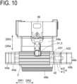
FIG. 10] FIG. 10 is a top view of the machine tool according to the second embodiment, schematically illustrating main configurations of the machine tool. - [
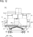
FIG. 11] FIG. 11 is a front view of the machine tool according to the second embodiment, schematically illustrating the machine tool. - [
FIG. 12] FIG. 12 is a front view of the machine tool according to the second embodiment, schematically illustrating the machine tool. - [
FIG. 13] FIG. 13 is a cross-sectional view of a first support member and a first cover, schematically illustrating a state in which the first support member supports the first cover. - [
FIG. 14] FIG. 14 is a cross-sectional view of the first support member and the first cover, schematically illustrating a state in which the first support member supports the first cover. - [
FIG. 15] FIG. 15 is an enlarged view of a part indicated by circle D1 inFIG. 13 . - [
FIG. 16] FIG. 16 is an enlarged view of a part indicated by circle D2 inFIG. 14 . - [
FIG. 17] FIG. 17 is an enlarged view of a part indicated by circle D3 inFIG. 14 . - [
FIG. 18] FIG. 18 is a perspective view of the machine tool, schematically illustrating some parts of the machine tool. - [
FIG. 19] FIG. 19 is a perspective view of the machine tool, schematically illustrating some parts of the machine tool. - [
FIG. 20] FIG. 20 is a perspective view of the machine tool, schematically illustrating some parts of the machine tool. - [
FIG. 21] FIG. 21 schematically illustrates a state in which a transporting step is being performed. - [
FIG. 22] FIG. 22 is an example flowchart of a method, according to an embodiment, of handling a machine tool. - By referring to the accompanying drawings, description will be made with regard to a
machine tool 1 according to an embodiment and with regard to a method, according to an embodiment, of handling themachine tool 1. It is noted that in the following description of the embodiments, identical reference numerals are used to denote identical portions, members, or components having identical functions, and redundant description of identical portions, members, or components will be eliminated or minimized. - In this specification, the terms "upward", "up", and "above" each refer to a direction oriented upward, from a lower portion, and the terms "downward", "down", and "below" each refer to a direction oriented downward, from an upper position. In this specification, the term "side" refers to a lateral direction (in other words, a direction other than "upward", "up", "above", "downward", "down", and "below").
- By referring to
FIGs. 1 to 3 , amachine tool 1A according to a first embodiment will be described.FIGs. 1 and2 each are a cross-sectional view of themachine tool 1A according to the first embodiment, schematically illustrating themachine tool 1A. It is to be noted thatFIG. 1 illustrates a state in which afirst cover 6 is positioned at a first position P1, andFIG. 2 illustrates a state in which thefirst cover 6 is positioned at a second position P2.FIG. 3 is a cross-sectional view of themachine tool 1A according to a modification of the first embodiment, schematically illustrating themachine tool 1A. - The
machine tool 1A according to the first embodiment includes a table 2, atool support 3, amover 4, afirst wall 51a, thefirst cover 6, and afirst support member 56a. - The table 2 supports a workpiece W (in other words, a to-be-worked object). In the example illustrated in
FIG. 1 , the table 2 is movable in a first direction DR1, and is movable in a second direction DR2, which is opposite to the first direction DR1. It is to be noted that the first direction DR1 is a direction in which the table 2 moves toward thefirst cover 6, and the second direction DR2 is a direction in which the table 2 moves away from thefirst cover 6. In the example illustrated inFIG. 1 , the first direction DR1 and the second direction DR2 each are a direction parallel to a horizontal direction. - The
tool support 3 supports a tool T, which is for machining the workpiece W. Thetool support 3 is movable in, for example, a direction parallel to a vertical direction. - The
mover 4 moves the table 2. In the example illustrated inFIG. 1 , themover 4 is capable of moving the table 2 in the first direction DR1, and is capable of moving the table 2 in the second direction DR2. - the
first wall 51a (in other words, a first side wall) is provided further in thefirst direction DR 1 than the table 2. thefirst wall 51a has a first opening OP1. thefirst wall 51a protects the table 2 and/or thetool support 3 on one side (more specifically, on the first direction DR1 side). - The
first cover 6 protrudes further in the first direction DR1 than thefirst wall 51a through the first opening OP1. Thefirst cover 6 prevents scattering of chips, coolant, and other substances in the first direction DR1 beyond thefirst cover 6. Thefirst cover 6 also protects the table 2 and/or themover 4 on one side (more specifically, on the first direction DR1 side). As described later, thefirst cover 6 is tiltable and, as such, can be referred to as "first tiltable cover". - The
first support member 56a supports thefirst cover 6 such that thefirst cover 6 is tiltable to decrease the amount of protrusion of the first cover 6 (the amount of protrusion in the first direction DR1) relative to thefirst wall 51a. - More specifically, the
first support member 56a supports thefirst cover 6 while thefirst cover 6 is tilting from the first position P1 to the second position P2 (seeFIG. 2 ). When thefirst cover 6 is positioned at the second position P2, the amount of protrusion by which thefirst cover 6 protrudes in the first direction DR1 relative to thefirst wall 51a is defined as second amount of protrusion A2 (seeFIG. 2 ). When thefirst cover 6 is positioned at the first position P1, the amount of protrusion by which thefirst cover 6 protrudes in the first direction DR1 relative to thefirst wall 51a is defined as first amount of protrusion A1 (seeFIG. 1 ). The second amount of protrusion A2 is smaller than the first amount of protrusion A1. - In the example illustrated in
FIG. 1 , when thefirst cover 6 is positioned at the first position P1, the first opening OP1 of thefirst wall 51a is closed by thefirst cover 6. Hence, the first position P1 can be referred to as closed position. In the example illustrated inFIG. 2 , when thefirst cover 6 is positioned at the second position P2, thefirst cover 6 is partially housed in the second direction DR2 relative to thefirst wall 51a. Hence, the second position P2 can be referred to as housing position. - In the
machine tool 1A according to the first embodiment, thefirst cover 6 can be caused to tilt in a direction in which the amount of protrusion of thefirst cover 6 is decreased relative to thefirst wall 51a. By decreasing the amount of protrusion of thefirst cover 6 in the first direction DR1 relative to thefirst wall 51a, themachine tool 1A as a whole is made compact in size (more specifically, size of themachine tool 1A during transportation). This configuration enables themachine tool 1A to be transported on general-purpose containers or smaller size transportation vehicles, and thus contributes to decarbonization and SDGs. - Also in the
machine tool 1A according to the first embodiment, thefirst cover 6 is supported by thefirst support member 56a in a state in which the amount of protrusion of thefirst cover 6 relative to thefirst wall 51a is decreased. In other words, during transportation of themachine tool 1A, it is not necessary to remove thefirst cover 6 from thefirst support member 56a. As a result, after transportation of themachine tool 1A, themachine tool 1A can be assembled quickly and easily. More specifically, thefirst support member 56a serves as a fulcrum on which thefirst cover 6 tilts in the direction to increase the amount of protrusion. Thus, thefirst cover 6 is changeable in position from the second position P2 (in other words, from the housing position) to the first position P1 (in other words, to the closed position). - In the state in which the position of the
first cover 6 is the first position P1, thefirst cover 6 protrudes further in the first direction DR1 than thefirst wall 51a. This makes themachine tool 1A larger in inner region. As a result, in the first embodiment, themachine tool 1A can be compact in size during transportation without compromising specifications of themachine tool 1A (such as the size of the table 2 and the movement stroke of the table 2 in a direction parallel to the first direction DR1). - As has been described hereinbefore, the first embodiment enables the
machine tool 1A to be compact in size during transportation, ensures easiness in the assembly of themachine tool 1A, and enables specifications of themachine tool 1A to be maintained. - In the examples illustrated in
FIGs. 1 and2 , thefirst cover 6 has a tilting axis AX. The tilting axis AX is parallel to a horizontal direction, and is provided at a lower end portion of thefirst cover 6. In the first embodiment (or in a second embodiment, described later), however, the tilting axis AX of thefirst cover 6 will not be limited to being parallel to the horizontal direction. The tilting axis AX of thefirst cover 6 also will not be limited to being provided at the lower end portion of thefirst cover 6. For example, as exemplified inFIG. 3 , the tilting axis AX of thefirst cover 6 may be parallel to the vertical direction. In other words, thefirst cover 6 may be tiltable about an axis parallel to the vertical direction. - By referring to
FIGs. 4 to 20 , amachine tool 1B according to the second embodiment will be described.FIGs. 4 and5 each are a front view of themachine tool 1B according to the second embodiment, schematically illustrating themachine tool 1B.FIG. 4 illustrates a state in which thefirst cover 6 is positioned at the first position P1, andFIG. 5 illustrates a state in which thefirst cover 6 is positioned at the second position P2.FIGs. 6 and7 each are a perspective view of themachine tool 1B according to the second embodiment, schematically illustrating themachine tool 1B.FIG. 6 illustrates a state in which thefirst cover 6 is positioned at the first position P1, andFIG. 7 illustrates a state in which thefirst cover 6 is positioned at the second position P2.FIG. 8 is a top view of themachine tool 1B according to the second embodiment, schematically illustrating main configurations (excluding configurations such as thefirst cover 6, asecond cover 7, and a wall 51) of themachine tool 1B.FIG. 9 is a side view of themachine tool 1B according to the second embodiment, schematically illustrating the main configurations (excluding configurations such as thefirst cover 6, thesecond cover 7, and the wall 51) of themachine tool 1B.FIG. 10 is a top view of themachine tool 1B according to the second embodiment, schematically illustrating the main configurations (excluding configurations such as thefirst cover 6, thesecond cover 7, and the wall 51) of themachine tool 1B.FIGs. 11 and12 each are a front view of themachine tool 1B according to the second embodiment, schematically illustrating themachine tool 1B.FIGs. 13 and14 each are a cross-sectional view of thefirst support member 56a and thefirst cover 6, schematically illustrating a state in which thefirst support member 56a supports thefirst cover 6.FIG. 15 is an enlarged view of a part indicated by circle D1 inFIG. 13 .FIG. 16 is an enlarged view of a part indicated by circle D2 inFIG. 14 .FIG. 17 is an enlarged view of a part indicated by circle D3 inFIG. 14 .FIGs. 18 to 20 each are a perspective view of themachine tool 1B, schematically illustrating some parts of themachine tool 1B. It is to be noted that inFIGs. 4 ,5 ,11 , and12 , a part of themachine tool 1B (the part surrounded by a single-dashed elongated circle) is cut away to show an internal configuration of themachine tool 1B. - In the second embodiment, the following description will mainly focus on those respects in which the second embodiment is different from the first embodiment, and those respects already described in the first embodiment will not be described in the second embodiment to avoid redundancy. Thus, it will be readily appreciated that those respects that are not explicitly described in the second embodiment but are described in the first embodiment apply in the second embodiment.
- As exemplified in
FIG. 4 , themachine tool 1B according to the second embodiment includes (1) the table 2, which supports a workpiece and is movable in the first direction DR1 and the second direction DR2, which is opposite to the first direction DR1, (2) thetool support 3, which supports a tool for machining the workpiece, (3) themover 4, which moves the table 2, (4) thefirst wall 51a, which is provided further in thefirst direction DR 1 than the table 2 and has the first opening OP1, (5) thefirst cover 6, which protrudes further in the first direction DR1 than thefirst wall 51a through the first opening OP1, and (6) thefirst support member 56a, which supports thefirst cover 6 such that thefirst cover 6 is tiltable to decrease the amount of protrusion of thefirst cover 6 relative to thefirst wall 51a. - With this configuration, the second embodiment provides effects similar to the effects of the first embodiment.
- Next, by referring to
FIGs. 4 to 20 , optional configurations employable in the second embodiment will be described. - In the examples illustrated in
FIGs. 6 and7 , thefirst cover 6 is changeable in position between the first position P1 (seeFIG. 6 ) and the second position P2 (seeFIG. 7 ). At the first position P1, the first opening OP1 of thefirst wall 51a is closed. At the second position P2, the amount of protrusion of thefirst cover 6 in the first direction DR1 relative to thefirst wall 51a is decreased. In the example illustrated inFIG. 7 , when thefirst cover 6 is positioned at the second position P2, a part of the first opening OP1 of thefirst wall 51a is open, instead of being closed by thefirst cover 6. - When the
first cover 6 is positioned at the second position P2 (seeFIG. 5 ), the amount of protrusion by which thefirst cover 6 protrudes in the first direction DR1 relative to thefirst wall 51a is defined as second amount of protrusion A2 (in the example illustrated inFIG. 5 , the second amount of protrusion A2 is zero, and thus there is no indication of "A2"). When thefirst cover 6 is positioned at the first position P1 (seeFIG. 4 ), the amount of protrusion by which thefirst cover 6 protrudes in the first direction DR1 relative to thefirst wall 51a is defined as first amount of protrusion A1. In this case, in the examples illustrated inFIGs. 4 and5 , the second amount of protrusion A2 is smaller than the first amount of protrusion A1. - In the example illustrated in
FIG. 5 , when thefirst cover 6 is positioned at the second position P2, thefirst cover 6 is entirely housed in the second direction DR2 relative to thefirst wall 51a. Alternatively, similarly to the example illustrated inFIG. 2 , when thefirst cover 6 is positioned at the second position P2, one part of thefirst cover 6 may protrude further in the first direction DR1 than thefirst wall 51a, and the other part of thefirst cover 6 may be housed in the second direction DR2 relative to thefirst wall 51a. In other words, the second amount of protrusion A2 may be a value larger than zero and smaller than the first amount of protrusion A1. - In the example illustrated in
FIG. 4 , as indicated by a broken-line arrow B1, thefirst cover 6 is tiltable from the first position P1 toward the second position P2 to cross a workpiece machining region AR1. More specifically, while thefirst cover 6 is tilting from the first position P1 toward the second position P2, thefirst cover 6 crosses the workpiece machining region AR1 of themachine tool 1B. The workpiece machining region AR1 becomes a temporary unused region during transportation of the machine tool. In the examples illustrated inFIGs. 4 and5 , the workpiece machining region AR1 can be utilized as a unused region in which thefirst cover 6 tilts to the second position P2. Thus, it is not necessary to provide a dedicated space or a dedicated movement passage for the tilting of thefirst cover 6. Also, for thefirst cover 6 to tilt, it is not necessary to withdraw any member from the movement passage of thefirst cover 6 or a smaller number of members needs to be withdrawn from the movement passage of thefirst cover 6. - It is to be noted that in this specification, the "workpiece machining region AR1" refers to a region that is a part of the region immediately above the table 2 and that is reachable by a tool supported by the
tool support 3. It is also to be noted that in a case where the table 2 is movable in a horizontal direction, the region immediately above the table 2 refers to a region immediately above the entire movable range of the table 2. - In the example illustrated in
FIG. 8 , the table 2 is movable in the first direction DR1 and the second direction DR2, which is opposite to the first direction DR1. Additionally, the table 2 may be movable in a direction different from a direction parallel to the first direction DR1. In the example illustrated inFIG. 8 , the table 2 is movable in a third direction DR3, which is perpendicular to the first direction DR1, and in a fourth direction DR4, which is opposite to the third direction DR3. It is to be noted that in the example illustrated inFIG. 8 , in the first direction DR1, the second direction DR2, the third direction DR3, and the fourth direction DR4 are parallel to a horizontal direction. - In the example illustrated in
FIG. 9 , thetool support 3 includes atool support member 31 and a support member mover 35. Thetool support member 31 supports a tool. The support member mover 35 moves thetool support member 31. In the example illustrated inFIG. 9 , thetool support member 31 is movable in directions parallel to the vertical direction (more specifically, in a vertically upward direction DR5 and a vertically downward direction DR6). The support member mover 35 moves thetool support member 31 in a direction parallel to the vertical direction. The support member mover 35 includes alinear guide 37 and adrive 38. Thelinear guide 37 guides thetool support member 31 to move in the directions parallel to the vertical direction. Thedrive 38 applies moving force to thetool support member 31. In the example illustrated inFIG. 9 , thelinear guide 37 is provided at acolumn 36. Thecolumn 36 is fixed to abase 91 of themachine tool 1B, and is provided further in the third direction DR3 than the table 2. - In the example illustrated in
FIG. 10 , themover 4, which moves the table 2, includes atable support member 41 and afirst drive 43. Thetable support member 41 supports the table 2 in a manner in which the table 2 is movable in a direction parallel to the first direction DR1. The first drive 43 (for example, a motor) applies moving force to the table 2 in the direction parallel to the first direction DR1. - In the example illustrated in
FIG. 10 , thetable support member 41 includes a first linear guide 42 (such as a first track). The firstlinear guide 42 guides the table 2 to move in the direction parallel to the first direction DR1. In this case, the table 2 is linearly movable along the firstlinear guide 42. - The
first drive 43 includes, for example, aball screw 431 and amotor 432. Themotor 432 drives theball screw 431 into rotation. Alternatively, thefirst drive 43 may include a linear motor. - As exemplified in
FIG. 10 , themover 4, which moves the table 2, may include a first expandable-contractable cover 44a. - The first expandable-
contractable cover 44a is provided on the first direction DR1 side relative to the table 2 to prevent foreign matter (such as workpiece chips, coolant, and other substances) from entering the space between the table 2 and thetable support member 41. The first expandable-contractable cover 44a expands as the table 2 moves in the second direction DR2, and contracts as the table 2 moves in the first direction DR1. In order to cause the first expandable-contractable cover 44a to expand and contract as the table 2 moves, one end portion of the first expandable-contractable cover 44a may be mounted on the table 2, and another end portion of the first expandable-contractable cover 44a may be mounted on thetable support member 41 orfirst aid tracks 45a. Thefirst aid tracks 45a are fixed to thetable support member 41. - In the example illustrated in
FIG. 10 , themover 4, which moves the table 2, includes thefirst aid tracks 45a. Thefirst aid tracks 45a aid the first expandable-contractable cover 44a in expanding and contracting in the direction parallel to the first direction DR1. In this case, the first expandable-contractable cover 44a smoothly expand and contract along thefirst aid tracks 45a. - As exemplified in
FIG. 10 , themover 4, which moves the table 2, may include a second expandable-contractable cover 44b. - The second expandable-
contractable cover 44b is provided on the second direction DR2 side relative to the table 2 to prevent foreign matter (such as workpiece chips, coolant, and other substances) from entering the space between the table 2 and thetable support member 41. The second expandable-contractable cover 44b expands as the table 2 moves in the first direction DR1, and contracts as the table 2 moves in the second direction DR2. In order to cause the second expandable-contractable cover 44b to expand and contract as the table 2 moves, one end portion of the second expandable-contractable cover 44b may be mounted on the table 2, and another end portion of the second expandable-contractable cover 44b may be mounted on thetable support member 41 or second aid tracks 45b. The second aid tracks 45b are fixed to thetable support member 41. - In the example illustrated in
FIG. 10 , themover 4, which moves the table 2, includes the second aid tracks 45b. The second aid tracks 45b aid the second expandable-contractable cover 44b in expanding and contracting in a direction parallel to the second direction DR2. In this case, the second expandable-contractable cover 44b smoothly expand and contract along the second aid tracks 45b. - As exemplified in
FIG. 9 , themover 4, which moves the table 2, may include a secondtable support member 46 and asecond drive 48. In the example illustrated inFIG. 9 , the secondtable support member 46 supports, via thetable support member 41, the table 2 in a manner in which the table 2 is movable in a direction parallel to the third direction DR3. Thesecond drive 48 applies moving force to thetable support member 41 in the direction parallel to the third direction DR3. - As exemplified in
FIG. 10 , themover 4, which moves the table 2, may include a third expandable-contractable cover 49a and/or a fourth expandable-contractable cover 49b. - The third expandable-
contractable cover 49a is provided on the third direction DR3 side relative to thetable support member 41 to prevent foreign matter (such as workpiece chips, coolant, and other substances) from entering the space between thetable support member 41 and the secondtable support member 46. The third expandable-contractable cover 49a expands as the table 2 and thetable support member 41 move in the fourth direction DR4, and contracts as the table 2 and thetable support member 41 move in the third direction DR3. - The fourth expandable-
contractable cover 49b is provided on the fourth direction DR4 side relative to thetable support member 41 to prevent foreign matter (such as workpiece chips, coolant, and other substances) from entering the space between thetable support member 41 and the secondtable support member 46. The fourth expandable-contractable cover 49b expands as the table 2 and thetable support member 41 move in the third direction DR3, and contracts as the table 2 and thetable support member 41 move in the fourth direction DR4. - In the example illustrated in
FIG. 5 , when thefirst cover 6 is positioned at the second position P2 (in other words, at the housing position), thefirst cover 6 is partially provided immediately above the table 2 and the mover 4 (for example, the firstlinear guide 42, which guides the table 2 to move, theball screw 431, or other elements). In this case, at least a part of the workpiece machining region AR1, which exists immediately above the table 2 and themover 4, can be utilized to partially or entirely house thefirst cover 6 further in the second direction DR2 than thefirst wall 51a. - In the example illustrated in
FIG. 5 , thefirst cover 6 positioned at the second position P2 contains at least one of a part of themover 4 and a part of the table 2. Specifically, when thefirst cover 6 is positioned at the second position P2, at least one of apart 4p of themover 4 and apart 2p of the table 2 is provided in an inner region AR2 of thefirst cover 6. In this case, when thefirst cover 6 is positioned at the second position P2, the inner region AR2 of thefirst cover 6 is effectively utilized. In the example illustrated inFIG. 5 , thefirst cover 6 positioned at the second position P2 contains both the part of themover 4 and the part of the table 2. Alternatively, thefirst cover 6 positioned at the second position P2 may contain one of the part of themover 4 and the part of the table 2. - While the
first cover 6 is tilting from the first position P1 to the second position P2, it is possible for thefirst cover 6 to interfere with a part of themover 4. In this case, the part of themover 4 that thefirst cover 6 may possibly interfere with is configured to be removable from a rest part of themover 4. - In the example illustrated in
FIG. 4 , a part of the mover 4 (for example, at least a part of the first expandable-contractable cover 44a and/or at least a part of thefirst aid tracks 45a) is removed from the rest part, 4r, of themover 4. In this case, thefirst cover 6 is caused to tilt from the first position P1 to the second position P2 in a state in which the part of themover 4 is removed from the rest part of themover 4. As exemplified inFIG. 11 , the removed part, 4s, of themover 4 is caused to be mounted on therest part 4r of themover 4 before themachine tool 1B is used. More specifically, in a state in which thefirst cover 6 is positioned at thefirst position P 1, thepart 4s of themover 4 is provided in the inner region AR2 of thefirst cover 6. - As exemplified in
FIG. 12 , a part of the table 2 that has moved furthest in the first direction DR1 may be providable in the inner region AR2 of thefirst cover 6 positioned at the first position P1. - In a case where the
part 4s of themover 4 or a part of the table 2 is providable in the inner region AR2 of thefirst cover 6 positioned at thefirst position P 1, the inner region AR2 can be used to expand the movable range of the table 2 in the direction parallel to the first direction DR1. - Additionally, as exemplified in
FIG. 12 , when thefirst cover 6 is positioned at thefirst position P 1, anozzle 93 may be provided in the inner region AR2 of thefirst cover 6. Through thenozzle 93, cleaning solution to wash away coolant attached to thefirst cover 6 is ejected. - In the examples illustrated in
FIGs. 4 and5 , thefirst support member 56a supports the lower end portion, 6g, of thefirst cover 6 such that thefirst cover 6 is tiltable. In this case, when thefirst cover 6 tilts, the amount of movement of thelower end portion 6g of thefirst cover 6 is smaller than the amount of movement of anupper end portion 6e of thefirst cover 6. Also, in a case where the amount of movement of thelower end portion 6g of thefirst cover 6 is relatively small, thefirst cover 6 can be caused to tilt more easily in a manner to avoid interference between thelower end portion 6g of thefirst cover 6 and the table 2 and themover 4. - In the examples illustrated in
FIGs. 4 and5 , the workpiece machining region AR1 exists immediately above the table 2 and themover 4 of themachine tool 1B. By utilizing the workpiece machining region AR1, adverse effects caused by the relatively large amount of movement of theupper end portion 6e of thefirst cover 6 are not actualized. In other words, in the examples illustrated inFIGs. 4 and5 , by utilizing the workpiece machining region AR1, theupper end portion 6e of thefirst cover 6 can be moved spaciously. - In the examples illustrated in
FIGs. 13 and14 , thefirst support member 56a supports the first cover 6 (more specifically, thelower end portion 6g of the first cover 6) such that thefirst cover 6 is tiltable about a first axis AX1. An example of thefirst support member 56a is apin member 561a. Thepin member 561a supports thefirst cover 6 such that thefirst cover 6 is tiltable. In the examples illustrated inFIGs. 13 and14 , thepin member 561a defines the first axis AX1, which is a tilting axis of thefirst cover 6. In the examples illustrated inFIGs. 13 and14 , the first axis AX1 is an axis parallel to a horizontal direction. - As exemplified in
FIG. 15 , thelower end portion 6g of thefirst cover 6 may include afirst hook 60b. Thefirst hook 60b is meshable and de-meshable with and from thepin member 561a. In a case where thefirst cover 6 includes thefirst hook 60b, thefirst cover 6 can be easily mounted, easily removed, or easily replaced. Thefirst hook 60b also permits thefirst cover 6 to tilt about thepin member 561a. With this configuration, thefirst hook 60b makes thefirst cover 6 easily attachable and detachable to and from thepin member 561a without blocking the tilting of thefirst cover 6 about thepin member 561a. For example, in the example illustrated inFIG. 15 (in other words, in the state in which thefirst cover 6 is positioned at the second position P2), thelower end portion 6g of thefirst cover 6 can be lifted upward (for example, diagonally upward) to remove thefirst cover 6 from thepin member 561a. It is to be noted that since weight is acting on thefirst cover 6, thefirst cover 6 does not come off from thepin member 561a unless thefirst cover 6 is lifted upward. - As exemplified in
FIG. 16 , themachine tool 1B may include a lowerfluid leakage guard 57. The lowerfluid leakage guard 57 is provided at thelower end portion 6g of thefirst cover 6. The lowerfluid leakage guard 57 prevents a leakage of coolant to outside the machine tool through the gap between thelower end portion 6g of thefirst cover 6 and thefirst wall 51a. - In the example illustrated in
FIG. 16 , the lowerfluid leakage guard 57 is attachable and detachable to and from thelower end portion 6g of thefirst cover 6. More specifically, the lowerfluid leakage guard 57 is attached to thelower end portion 6g of thefirst cover 6 after thefirst cover 6 has tilted from the second position P2 (in other words, from the housing position) to the first position P1 (in other words, to the closed position to close the first opening OP1). - As exemplified in
FIG. 17 , themachine tool 1B may include an upperfluid leakage guard 58. The upperfluid leakage guard 58 is provided at theupper end portion 6e of thefirst cover 6. The upperfluid leakage guard 58 prevents a leakage of coolant to outside the machine tool through the gap between theupper end portion 6e of thefirst cover 6 and thefirst wall 51a. - In the example illustrated in
FIG. 13 , the upperfluid leakage guard 58 is fixed to theupper end portion 6e of thefirst cover 6. In other words, when thefirst cover 6 tilts relative to thefirst support member 56a, the upperfluid leakage guard 58 tilts together with thefirst cover 6. As exemplified inFIG. 13 , when thefirst cover 6 is positioned at the second position P2, the upperfluid leakage guard 58 is located away from thefirst wall 51a. As exemplified inFIG. 14 , when thefirst cover 6 is positioned at the first position P1, the upperfluid leakage guard 58 is in contact with thefirst wall 51a. - In the example illustrated in
FIG. 14 , thefirst cover 6 includes ahollow protrusion 65 and astopper 66. Theprotrusion 65 protrudes in the first direction DR1 through the first opening OP1 of thefirst wall 51a. A tilting direction oriented from the second position P2 toward the first position P1 is defined as first tilting direction DR7. Thestopper 66 prevents thefirst cover 6 from tilting in the first tilting direction DR7past the first position P1. In other words, thestopper 66 defines a tilting limitation position for the tilting of thefirst cover 6 in the first tilting direction DR7. - In the example illustrated in
FIG. 17 , the upperfluid leakage guard 58 serves as a part of thestopper 66. In other words, the upperfluid leakage guard 58 serves as one member that defines the tilting limitation position for the tilting of thefirst cover 6 in the first tilting direction DR7. - As exemplified in
FIG. 14 , thefirst cover 6 has anouter surface 60u and aninner surface 60n. Theouter surface 60u is exposed to outside the machine tool. Theinner surface 60n defines the inner region AR2 of thefirst cover 6. Also in the example illustrated inFIG. 14 , the first cover 6 (more specifically, theouter surface 60u of the first cover 6) has abottom surface 61s, anupper surface 62s, and afirst end surface 631s, which is the first direction DR1 side face. Thefirst end surface 631s is a part of aside surface 63s of thefirst cover 6. As exemplified inFIG. 6 , theside surface 63s of thefirst cover 6 may have asurface 632s andsurface 633s, in addition to thefirst end surface 631s. Thesurface 632s is the third direction DR3 side face. Thesurface 633s is the fourth direction DR4 side face, which is opposite to the third direction DR3 side face. - In the example illustrated in
FIG. 14 , a height of a position of thebottom surface 61s of thefirst cover 6 positioned at the first position P1 increases in the first direction DR1. In this case, the amount of protrusion of thefirst cover 6 in the first direction DR1 relative to thefirst wall 51a can be easily decreased. For example, when thefirst cover 6 is moved from the first position P1 to the second position P2 (seeFIG. 13 ), causing thefirst cover 6 to tilt by an angle smaller than 90 degrees about the first axis AX1 suffices (more specifically, by an angle smaller than 75 degrees or an angle smaller than 60 degrees). In the example illustrated inFIG. 13 , thefirst cover 6 is caused to tilt by an angle smaller than 90 degrees from the first position P1 toward the second position P2. This configuration ensures that an entire part of thefirst end surface 631s of the first cover 6 (or a majority part of thefirst end surface 631s) is housed in the second direction DR2 relative to thefirst wall 51a. - Also in a case where the height of the position of the
bottom surface 61s of thefirst cover 6 increases in the first direction DR1, coolant that has reached thefirst cover 6 can be guided in the second direction DR2 along abottom wall 61 of the first cover 6 (more specifically, aninner surface 61n of the bottom wall 61), as exemplified inFIG. 16 (see broken-line arrow B4). In other words, coolant scattering toward thefirst cover 6 can be collected using the inclination of thebottom wall 61 of thefirst cover 6. - As has been described hereinbefore, in a case where the height of the position of the
bottom surface 61s of thefirst cover 6 increases in the first direction DR1, thefirst cover 6 can be easily housed, ensuring that coolant can be easily collected. - In the example illustrated in
FIG. 16 , thefirst cover 6 includes, as its component, a plurality of plate members (for example, a plurality of metal plates). In other words, a plurality of plate members are connected together to form thefirst cover 6. - In the example illustrated in
FIG. 18 , thefirst cover 6 includes afixation member 67. Thefixation member 67 fixes thefirst cover 6 to the second position P2. In a case where thefirst cover 6 includes thefixation member 67, themachine tool 1B can be transported in a state in which thefirst cover 6 is fixed to the second position P2. In this case, thefirst cover 6 is prevented from rattling during transportation of themachine tool 1B. - In the example illustrated in
FIG. 18 , in a state in which thefirst cover 6 is positioned at the second position P2, thefixation member 67 is provided at a position where thefixation member 67 is accessible by a user through the first opening OP1 when the user is positioned further in thefirst direction DR 1 than thefirst wall 51a (in other words, a position where thefixation member 67 is within reach of a hand of a user positioned outside themachine tool 1B). In this case, the user is able to fix thefixation member 67 to astructure member 11a of themachine tool 1B without entering themachine tool 1B. Also in the above case, the user is able to release the fixing of thefixation member 67 to thestructure member 11a without entering themachine tool 1B. It is to be noted that in a state in which thefirst cover 6 is positioned at the second position P2, thefixation member 67 or a fixture member fixing thefixation member 67 to thestructure member 11a is preferably visually recognizable through the first opening OP1 from a position further in thefirst direction DR 1 than thefirst wall 51a. In this case, the user is able to more easily fix thefixation member 67 or release the fixing of thefixation member 67 without entering themachine tool 1B. - In the example illustrated in
FIG. 18 , thefixation member 67 is fixed to thestructure member 11a via a fixture member (for example, via abracket 82a and abolt 81a). In the example illustrated inFIG. 19 , thefixation member 67 has first holes 67h. The first holes 67h are each capable of receiving a connection member such as thebolt 81a. - In the example illustrated in
FIG. 6 , themachine tool 1B includes a plurality ofwalls 51. The plurality ofwalls 51 include thefirst wall 51a, which is provided on the first direction DR1 side of themachine tool 1B; and thesecond wall 51b, which is provided at the second direction DR2 side of themachine tool 1B. The plurality ofwalls 51 may include athird wall 51c and afourth wall 51d. Thethird wall 51c is provided on the third direction DR3 side of themachine tool 1B. Thefourth wall 51d is provided on the fourth direction DR4 side of themachine tool 1B. Each of thefirst wall 51a, thesecond wall 51b, thethird wall 51c, and thefourth wall 51d may be made up of a plurality of members. For example, thefirst wall 51a may include a plurality of plate members or a plurality of panels. Similarly, each of thesecond wall 51b, thethird wall 51c, and thefourth wall 51d may include a plurality of plate members or a plurality of panels. - In the example illustrated in
FIG. 6 , themachine tool 1B includes a plurality of connection members 86 (for example, a plurality of bolts). The plurality ofconnection members 86 fix thefirst cover 6 positioned at the first position P1 to thefirst wall 51a. In the example illustrated inFIG. 7 , thefirst wall 51a includes a plurality ofsecond holes 51h. The plurality ofsecond holes 51h respectively receive the plurality ofconnection members 86. In the example illustrated inFIG. 7 , some of the plurality ofsecond holes 51h are provided further in the third direction DR3 than the first opening OP1, and other of the plurality ofsecond holes 51h are provided further in the fourth direction DR4 than the first opening OP1. - In the example illustrated in
FIG. 7 , thefourth wall 51d supports an openable-closable door 92. It is to be noted that in a case where the side on which thedoor 92 is provided is defined as front surface, thefourth wall 51d may be referred to as front wall. It is also to be noted that in a case where in plan view, the direction from the table 2 toward thecolumn 36, which movably supports thetool support member 31, is defined as rearward, thethird wall 51c may be referred to as rear wall. In the example illustrated inFIG. 7 , thefirst cover 6 is provided at thefirst wall 51a, which is different from the rear wall. - In the example illustrated in
FIG. 7 , themachine tool 1B has at least four walls (thefirst wall 51a, thesecond wall 51b, thethird wall 51c, and thefourth wall 51d). Themachine tool 1B may have five or more walls. - In the examples illustrated in
FIGs. 4 and5 , themachine tool 1B includes (1) thesecond wall 51b, which has a second opening OP2 and is provided further in the second direction DR2 than the table 2, (2) thesecond cover 7, which protrudes further in the second direction DR2 than thesecond wall 51b through the second opening OP2, and (3) asecond support member 56b, which supports thesecond cover 7 such that thesecond cover 7 is tiltable to decrease the amount of protrusion of thesecond cover 7 relative to thesecond wall 51b. In the examples illustrated inFIGs. 4 and5 , the position of thesecond cover 7 is changeable between a third position P3 and a fourth position P4. At the third position P3, thesecond cover 7 closes the second opening OP2 of thesecond wall 51b. At the fourth position P4, the amount of protrusion of thesecond cover 7 in the second direction DR2 relative to thesecond wall 51b is decreased. - The
machine tool 1B includes thesecond cover 7 in addition to thefirst cover 6, which is tiltable in a direction toward the table 2. Thesecond cover 7 is tiltable in the direction toward the table 2. In a case where themachine tool 1B includes thesecond cover 7 in addition to thefirst cover 6, themachine tool 1B can be more compact in size during transportation of themachine tool 1B. - In the example illustrated in
FIG. 4 , thesecond cover 7 is tiltable to cross the workpiece machining region AR1 from the third position P3 toward the fourth position P4 (see broken-line arrow B2). In this case, it is not necessary to provide a dedicated space or a dedicated movement passage for the tilting of thesecond cover 7. - In the example illustrated in
FIG. 4 , thesecond support member 56b supports alower end portion 7g of the second cover such that the second cover is tiltable. In this case, it is easy for thesecond cover 7 to tilt to ensure that thelower end portion 7g of thesecond cover 7 does not interfere with the table 2 and themover 4. - In the example illustrated in
FIG. 4 , thesecond cover 7 has abottom surface 71s. A height of a position of thebottom surface 71s increases in the second direction DR2. In this case, the amount of protrusion of thesecond cover 7 in the second direction DR2 relative to thesecond wall 51b can be easily decreased. For example, when thesecond cover 7 is moved from the third position P3 to the fourth position P4 (seeFIG. 5 ), causing thesecond cover 7 to tilt by an angle smaller than 90 degrees suffices. - In the example illustrated in
FIG. 5 , thesecond cover 7 positioned at the fourth position P4 contains at least one of a part of themover 4 and a part of the table 2. In this case, when thesecond cover 7 is positioned at the fourth position P4, an inner region AR3 of thesecond cover 7 is effectively utilized. - As exemplified in
FIG. 5 , thesecond cover 7 positioned at the fourth position P4 may contain a part of the firstlinear guide 42, which guides the table 2 to move. Also as exemplified inFIG. 5 , thesecond cover 7 positioned at the fourth position P4 may contain a part of thefirst drive 43, which moves the table 2 (for example, themotor 432 and a part of the ball screw 431). - In the example illustrated in
FIG. 11 , thesecond cover 7 positioned at the third position P3 contains a part of the mover 4 (for example, a part of the second expandable-contractable cover 44b and/or a part of the second aid tracks 45b). In this case, the movable range of the table 2 in a direction parallel to the second direction DR2 can be expanded using the inner region AR3 of thesecond cover 7 positioned at the third position P3. - In the example illustrated in
FIG. 20 , thesecond cover 7 includes afixation member 77. Thefixation member 77 fixes thesecond cover 7 to the fourth position P4. Also, in a state in which thesecond cover 7 is positioned at the fourth position P4, thefixation member 77 is provided at a position where thefixation member 77 is accessible by a user through the second opening OP2 when the user is positioned further in the second direction DR2 than thesecond wall 51b. Thefixation member 77 is fixed to astructure member 11b via a fixture member (for example, abracket 82b and abolt 81b). It is to be noted that in a state in which thesecond cover 7 is positioned at the fourth position P4, thefixation member 77 or a fixture member fixing thefixation member 77 to thestructure member 11b is preferably visually recognizable through the second opening OP2 from a position further in the second direction DR2 than thesecond wall 51b. - By referring to
FIGs. 1 to 22 , a method, according to this embodiment, of handling themachine tool 1 will be described.FIG. 21 schematically illustrates a state in which a transporting step is being performed.FIG. 22 is an example flowchart of the method, according to this embodiment, of handling themachine tool 1. - At first step ST1, the
machine tool 1 is prepared. First step ST1 is a preparing step. Themachine tool 1 prepared in the preparing step may be themachine tool 1A according to the first embodiment, themachine tool 1B according to the second embodiment, or any other machine tool. - As exemplified in
FIGs. 2 ,5 , and other figures, themachine tool 1 prepared in the preparing step includes (1) the table 2, which is configured to move in the first direction DR1 and support a workpiece, (2) thetool support 3, which supports a tool, (3) themover 4, which moves the table 2, (4) thefirst wall 51a, which is provided further in thefirst direction DR 1 than the table 2, (5) thefirst cover 6, which is capable of protruding in the first direction DR1 through the first opening OP1 of thefirst wall 51a, and (6) thefirst support member 56a, supports thefirst cover 6 such that thefirst cover 6 is tiltable. - The
first support member 56a supports thefirst cover 6 such that thefirst cover 6 is tiltable between the first position P1 and the second position P2. When thefirst cover 6 is positioned at the first position P1, the first opening OP1 of thefirst wall 51a is closed by thefirst cover 6. When thefirst cover 6 is positioned at the second position P2, the amount of protrusion of thefirst cover 6 in the first direction DR1 relative to the first wall 5 1a is decreased. - At second step ST2, the
first cover 6 is fixed to the second position P2. Second step ST2 is a first fixing step. The first fixing step includes fixing thefixation member 67 of the first cover 6 (for example, the first holes 67h) to thestructure member 11a of themachine tool 1 via a fixture member (seeFIG. 18 ). The first fixing step is preferably performed by a user positioned further in thefirst direction DR 1 than thefirst wall 51a. In other words, in a state in which thefirst cover 6 is positioned at the second position P2, thefixation member 67 is preferably provided at a position where thefixation member 67 is accessible by a user through the first opening OP1 when the user is positioned further in thefirst direction DR 1 than thefirst wall 51a. In this case, the user is able to fix thefixation member 67 to thestructure member 1 1a of themachine tool 1 without entering themachine tool 1. It is to be noted that in a state in which thefirst cover 6 is positioned at the second position P2, thefixation member 67 or the fixture member fixing thefixation member 67 to thestructure member 11a is preferably visually recognizable through the first opening OP1 from a position further in thefirst direction DR 1 than thefirst wall 51a. In this case, the user is able to more easily fix thefixation member 67 to thestructure member 11a of themachine tool 1 without entering themachine tool 1. - In a case where the
machine tool 1 includes thesecond cover 7, the method of handling themachine tool 1 may include a step of fixing thesecond cover 7 to the fourth position P4 (seeFIG. 20 ). - As exemplified in
FIG. 21 , at third step ST3, themachine tool 1 is transported. Third step ST3 is a transporting step. In the transporting step, themachine tool 1 is transported in a state in which thefirst cover 6 is fixed to the second position P2, at which the amount of protrusion of thefirst cover 6 in the first direction DR1 relative to the first wall 5 1a is decreased. - In the example illustrated in
FIG. 21 , the amount of protrusion of thefirst cover 6 in the first direction DR1 relative to thefirst wall 51a is decreased. This ensures that themachine tool 1 can be transported on a smaller size transportation vehicle V. For example, in the transporting step, a track can be used instead of a trailer. In the transporting step, the size of themachine tool 1 in a direction parallel to the first direction DR1 (more specifically, the width of the machine tool 1) may be 250 cm or less, 240 cm or less, or 230 cm or less. - The
machine tool 1 may also be transported on a general-purpose 40-feet container or a general-purpose 20-feet container. - In a case where the
machine tool 1 can be transported on a smaller size transportation vehicle or a general-purpose container, the amount of discharge of carbon dioxide discharged during transportation is decreased, and a worker's labor associated with transportation is saved. - In the transporting step, the
first cover 6 fixed to the second position P2 preferably contains at least one of a part of themover 4 and a part of the table 2 (see, if necessary,FIG. 5 ). In this case, the inner region AR2 of thefirst cover 6 is effectively utilized during transportation of themachine tool 1. - At fourth step ST4, the
machine tool 1 transported at third step ST3 is provided at an installment site of the machine tool (for example, the inside of a building such as a factory). Fourth step ST4 is a providing step. - At fifth step ST5, the
first cover 6 is caused to tilt in the first tilting direction DR7 from the second position P2 toward the first position P1 (seeFIG. 5 ). Fifth step ST5 is a tilting step. In the tilting step, thefirst cover 6 is caused to tilt from the second position P2 to the first position P1 to increase the amount of protrusion of thefirst cover 6 in the first direction DR1 relative to thefirst wall 51a. - The tilting step preferably includes causing the
first cover 6 to tilt to cross the workpiece machining region AR1. In a case where the workpiece machining region AR1 is utilized as the movement passage of thefirst cover 6, it is not necessary to withdraw any member from the movement passage of thefirst cover 6 or a smaller number of members needs to be withdrawn from the movement passage of thefirst cover 6. - In a case where the
machine tool 1 includes thesecond cover 7, the method of handling themachine tool 1 may include causing thesecond cover 7 to tilt from the fourth position P4 to the third position P3 to increase the amount of protrusion of thesecond cover 7 in the second direction DR2 relative to thesecond wall 51b (see broken-line arrow B3 inFIG. 5 ). - At sixth step ST6, the
first cover 6 is fixed to the first position P1. Sixth step ST6 is a second fixing step. The second fixing step includes fixing thefirst cover 6 to thefirst wall 51a. In the example illustrated inFIG. 6 , the second fixing step includes fixing thefirst cover 6 to thefirst wall 51a via theconnection members 86. - In a case where the
machine tool 1 includes thesecond cover 7, the method of handling themachine tool 1 may include fixing thesecond cover 7 to the third position P3. - As exemplified in
FIG. 5 , at sixth step ST6 (more specifically, when thefirst cover 6 is caused to tilt in the first tilting direction DR7), there may be a case where a part of themover 4 has been removed from therest part 4r of themover 4. In this case, at seventh step ST7, the part of themover 4 is attached to therest part 4r of themover 4. Seventh step ST7 is an attaching step. - In the example illustrated in
FIG. 11 , the attaching step (seventh step ST7) includes attaching at least a part of the first expandable-contractable cover 44a and/or at least a part of thefirst aid tracks 45a to therest part 4r of themover 4. Additionally, the attaching step (seventh step ST7) may include attaching at least a part of the second expandable-contractable cover 44b and/or at least a part of the second aid tracks 45b to therest part 4r of themover 4. - In the example illustrated in
FIG. 11 , thepart 4s of themover 4 to be attached to therest part 4r of themover 4 is provided in the inner region AR2 of thefirst cover 6 positioned at the first position P1. Also, anotherpart 4q of themover 4 to be attached to therest part 4r of themover 4 is provided in the inner region AR3 of thesecond cover 7 positioned at the third position P3. In this case, utilizing the inner region AR2 of thefirst cover 6 or the inner region AR3 of thesecond cover 7 ensures that the movable range of the table 2 is expanded in the direction parallel to the first direction DR1. - The present invention will not be limited to the above-described and/or modifications; it will be appreciated that the embodiments may be modified or changed in any manner deemed convenient within the technical spirit and scope of the present invention. Also, the various techniques used in each of the embodiments and/or modifications are applicable in other embodiments and/or modifications insofar as no technical contradiction occurs. Further, the optional configurations in the embodiments and/or modifications may be omitted in any manner deemed convenient.
- 1, 1A, 1B ... Machine tool, 2 ... Table, 2p ... Part of table, 3 ... Tool support, 4 ... Mover, 4p, 4q, 4s ... Part of mover, 4r ... Rest part of mover, 6 ... First cover, 6e ... Upper end portion, 6g ... Lower end portion, 7 ... Second cover, 7g ... Lower end, 11a, 11b ... Structure member, 31 ... Tool support member, 35 ... Support member mover, 36 ... Column, 37 ... Linear guide, 38 ... Drive, 41 ... Table support member, 42 ... First linear guide, 43 ... First drive, 44a ... First expandable-contractable cover, 44b ... Second expandable-contractable cover, 45a ... First aid track, 45b ... Second aid track, 46 ... Second table support member, 48 ... Second drive, 49a ... Third expandable-contractable cover, 49b ... Fourth expandable-contractable cover, 51 ... Wall, 51a ... First wall, 51b ... Second wall, 51c ... Third wall, 51d ... Fourth wall, 51h ... Second hole, 56a ... First support member, 56b ... Second support member, 57 ... Lower fluid leakage guard, 58 ... Upper fluid leakage guard, 60b ... First hook, 60n ... Inner surface, 60u ... Outer surface, 61 ... Bottom wall, 61n ... Inner surface, 61s ... Bottom surface, 62s ... Upper surface, 63s ... Side surface, 65 ... Protrusion, 66 ... Stopper, 67 ... Fixation member, 67h ... First hole, 71s ... Bottom surface, 77 ... Fixation member, 81a, 81b ... Bolt, 82a, 82b ... Bracket, 86 ... Connection member, 91 ... Base, 92 ... Door, 93 ... Nozzle, 431 ... Ball screw, 432 ... Motor, 561a ... Pin member, 631s ... First end surface, 632s ... Third direction side surface, 633s ... Fourth direction side surface, AR1 ... Workpiece machining region, AR2 ... Inner region of first cover, AR3 ... Inner region of second cover,
OP 1 ... First opening, OP2 ... Second opening, T ... Tool, V ... Transportation vehicle, W ... Workpiece
Claims (11)
- A machine tool comprising:a table configured to support a workpiece and move in a first direction and a second direction opposite to the first direction;a tool support configured to support a tool for machining the workpiece;a mover configured to move the table;a first wall provided further in the first direction than the table and having a first opening;a first cover protruding further in the first direction than the first wall through the first opening; anda first support member supporting the first cover such that the first cover is tiltable to decrease an amount of protrusion of the first cover relative to the first wall.
- The machine tool according to claim 1, wherein the first cover is changeable in position between:a first position at which the first opening of the first wall is closed; anda second position at which the amount of protrusion of the first cover in the first direction relative to the first wall is decreased.
- The machine tool according to claim 2, wherein the first cover is tiltable from the first position toward the second position to cross a workpiece machining region.
- The machine tool according to claim 3, wherein the first cover positioned at the second position contains at least one of a part of the mover and a part of the table.
- The machine tool according to any one of claims 2 to 4, wherein a part of the mover is provided in an inner region of the first cover positioned at the first position.
- The machine tool according to any one of claims 2 to 5,wherein the first cover comprises a fixation member fixing the first cover to the second position, andwherein when the first cover is positioned at the second position and when a user is positioned further in the first direction than the first wall, the fixation member is provided at a position accessible by the user through the first opening.
- The machine tool according to any one of claims 1 to 6, wherein the first support member supports a lower end portion of the first cover such that the first cover is tiltable.
- The machine tool according to claim 7,wherein the first cover has a bottom surface, andwherein a height of a position of the bottom surface increases in the first direction.
- The machine tool according to claim 7 or 8,further comprising a fluid leakage guard configured to prevent a leakage of a coolant to outside the machine tool through a gap between the lower end portion of the first cover and the first wall, andwherein the fluid leakage guard is attachable and detachable to and from the lower end portion of the first cover.
- The machine tool according to any one of claims 1 to 9, further comprising:a second wall provided further in the second direction than the table and having a second opening;a second cover protruding further in the second direction than the second wall through the second opening; anda second support member configured to support the second cover such that the second cover is tiltable to decrease an amount of protrusion of the second cover relative to the second wall.
- A method of handling a machine tool, the method comprising:a step of preparing a machine tool, the machine tool comprising a table configured to support a workpiece and move in a first direction, a tool support configured to support a tool, a mover configured to move the table, a first wall provided further in the first direction than the table, a first cover configured to protrude in the first direction through a first opening of the first wall, and a first support member supporting the first cover such that the first cover is tiltable;a step of transporting the machine tool in a state in which the first cover is fixed to a second position at which an amount of protrusion of the first cover in the first direction relative to the first wall decreased;a step of installing the transported machine tool at an installment site;a tilting step of causing the first cover to tilt from the second position to the first position to increase the amount of protrusion of the first cover in the first direction relative to the first wall; anda step of fixing the first cover to the first position.
Applications Claiming Priority (1)
| Application Number | Priority Date | Filing Date | Title |
|---|---|---|---|
| PCT/JP2021/048011 WO2023119591A1 (en) | 2021-12-23 | 2021-12-23 | Machine tool and machine tool handling method |
Publications (2)
| Publication Number | Publication Date |
|---|---|
| EP4438227A1 true EP4438227A1 (en) | 2024-10-02 |
| EP4438227A4 EP4438227A4 (en) | 2025-01-08 |
Family
ID=85330628
Family Applications (1)
| Application Number | Title | Priority Date | Filing Date |
|---|---|---|---|
| EP21969026.0A Pending EP4438227A4 (en) | 2021-12-23 | 2021-12-23 | MACHINE TOOL AND METHOD FOR HANDLING A MACHINE TOOL |
Country Status (5)
| Country | Link |
|---|---|
| US (1) | US20240326188A1 (en) |
| EP (1) | EP4438227A4 (en) |
| JP (1) | JP7230283B1 (en) |
| CN (1) | CN118450964A (en) |
| WO (1) | WO2023119591A1 (en) |
Family Cites Families (22)
| Publication number | Priority date | Publication date | Assignee | Title |
|---|---|---|---|---|
| JPS5723945U (en) * | 1980-07-15 | 1982-02-06 | ||
| JPH04122437U (en) * | 1991-04-24 | 1992-11-04 | 日立精機株式会社 | cover door in machine tool |
| JPH0750130Y2 (en) * | 1991-05-07 | 1995-11-15 | 日立精機株式会社 | Machine tool splash guard |
| US5181898A (en) * | 1991-09-16 | 1993-01-26 | Cincinnati Milacron, Inc. | Cover assembly for multi-configurable machine tool |
| JPH09314437A (en) * | 1996-05-27 | 1997-12-09 | Roland D G Kk | Equipment with swivel cover |
| JPH11300572A (en) * | 1998-04-16 | 1999-11-02 | Okuma Corp | Chip scattering preventing cover for machine tool |
| JP3741248B2 (en) * | 1998-06-02 | 2006-02-01 | 日立ビアメカニクス株式会社 | Printed circuit board drilling device and maintenance method |
| JP2000061704A (en) * | 1998-08-24 | 2000-02-29 | Mori Seiki Co Ltd | Machine tool work unloading device |
| JP2001132310A (en) * | 1999-11-05 | 2001-05-15 | Matsushita Electric Ind Co Ltd | door |
| JP2001138173A (en) * | 1999-11-17 | 2001-05-22 | Hitachi Seiki Co Ltd | Splash guard opening and closing door device |
| JP2002322860A (en) * | 2001-04-27 | 2002-11-08 | Okuma Corp | Automatic double door |
| JP2004009256A (en) * | 2002-06-10 | 2004-01-15 | Matsuda Kogyo:Kk | Foldable working cover |
| JP4768257B2 (en) * | 2004-12-21 | 2011-09-07 | 株式会社岡本工作機械製作所 | Fully closed cover device for machine tools |
| CN101505916B (en) * | 2006-09-04 | 2011-03-16 | 株式会社牧野铣床制作所 | Splash guard for machine tool |
| JP2011143483A (en) * | 2010-01-12 | 2011-07-28 | Disco Abrasive Syst Ltd | Opening/closing door structure for machining device cover |
| DE202011103226U1 (en) * | 2011-07-15 | 2011-11-09 | Iecon Gmbh | machine tool |
| JP5936972B2 (en) * | 2012-09-25 | 2016-06-22 | 株式会社ディスコ | Processing equipment |
| KR20140095160A (en) * | 2013-01-23 | 2014-08-01 | 두산인프라코어 주식회사 | Opening and shutting device of door for machine tool |
| CN108326628A (en) * | 2018-01-16 | 2018-07-27 | 宁夏共享机床辅机有限公司 | A kind of machine shield with precision holding effect |
| JP6948985B2 (en) * | 2018-05-30 | 2021-10-13 | シチズン時計株式会社 | Machine tool cover device |
| JP6956699B2 (en) * | 2018-09-28 | 2021-11-02 | 旭精機工業株式会社 | Machine tool door mechanism |
| CN109773223A (en) * | 2019-01-17 | 2019-05-21 | 上海大学 | A universal protective device for safe production of machine tools |
-
2021
- 2021-12-23 EP EP21969026.0A patent/EP4438227A4/en active Pending
- 2021-12-23 JP JP2022532787A patent/JP7230283B1/en active Active
- 2021-12-23 CN CN202180105126.3A patent/CN118450964A/en active Pending
- 2021-12-23 WO PCT/JP2021/048011 patent/WO2023119591A1/en not_active Ceased
-
2024
- 2024-06-14 US US18/743,111 patent/US20240326188A1/en active Pending
Also Published As
| Publication number | Publication date |
|---|---|
| WO2023119591A1 (en) | 2023-06-29 |
| JP7230283B1 (en) | 2023-02-28 |
| JPWO2023119591A1 (en) | 2023-06-29 |
| EP4438227A4 (en) | 2025-01-08 |
| CN118450964A (en) | 2024-08-06 |
| US20240326188A1 (en) | 2024-10-03 |
Similar Documents
| Publication | Publication Date | Title |
|---|---|---|
| EP1462579B1 (en) | Hydraulic shovel with counterweight | |
| US11203853B2 (en) | Cabin assembly for construction equipment | |
| CN101505916B (en) | Splash guard for machine tool | |
| EP1924467B1 (en) | frame structure for construction machine | |
| EP2664717B1 (en) | Cab frame for a construction machine | |
| EP3366899A1 (en) | Utility vehicle, and method for adjusting position of movable part of utility vehicle | |
| US7604077B2 (en) | Removable hood panel | |
| EP4504538A1 (en) | Bracket assembly for attaching component to vehicle | |
| JP7230283B1 (en) | Machine tools and how to handle them | |
| KR100845998B1 (en) | Machine tool | |
| EP3825158B1 (en) | Refrigeration unit for transportation, and method of assembling refrigeration unit for transportation | |
| EP1731410B1 (en) | Steering support member structure | |
| JP2019052806A (en) | Transport refrigeration unit and assembly method of the same | |
| JP2008162340A (en) | In-vehicle electronic device mounting structure | |
| CN105887961B (en) | Excavator | |
| JP6431154B1 (en) | Passenger partition door unit structure | |
| JP2009035235A (en) | Swivel work vehicle | |
| KR20110055995A (en) | Expansion Tank Tilt Fixture for Construction Machinery | |
| JP3526078B2 (en) | Instrument panel mounting structure | |
| CN220283258U (en) | Support structure of escalator and lower support member therefor | |
| KR20260028211A (en) | Slope structure of low-floor truck | |
| JP7780144B2 (en) | Exterior wall unit, building structure, and installation method of exterior wall unit | |
| JP2012011825A (en) | Vehicle body front structure | |
| JP2025074112A (en) | Work Machine | |
| JP2001071945A (en) | Car body front structure |
Legal Events
| Date | Code | Title | Description |
|---|---|---|---|
| STAA | Information on the status of an ep patent application or granted ep patent |
Free format text: STATUS: THE INTERNATIONAL PUBLICATION HAS BEEN MADE |
|
| PUAI | Public reference made under article 153(3) epc to a published international application that has entered the european phase |
Free format text: ORIGINAL CODE: 0009012 |
|
| STAA | Information on the status of an ep patent application or granted ep patent |
Free format text: STATUS: REQUEST FOR EXAMINATION WAS MADE |
|
| 17P | Request for examination filed |
Effective date: 20240624 |
|
| AK | Designated contracting states |
Kind code of ref document: A1 Designated state(s): AL AT BE BG CH CY CZ DE DK EE ES FI FR GB GR HR HU IE IS IT LI LT LU LV MC MK MT NL NO PL PT RO RS SE SI SK SM TR |
|
| STAA | Information on the status of an ep patent application or granted ep patent |
Free format text: STATUS: EXAMINATION IS IN PROGRESS |
|
| A4 | Supplementary search report drawn up and despatched |
Effective date: 20241211 |
|
| RIC1 | Information provided on ipc code assigned before grant |
Ipc: B23Q 1/52 20060101ALI20241205BHEP Ipc: B23Q 11/08 20060101AFI20241205BHEP |
|
| 17Q | First examination report despatched |
Effective date: 20250102 |
|
| DAV | Request for validation of the european patent (deleted) | ||
| DAX | Request for extension of the european patent (deleted) | ||
| GRAP | Despatch of communication of intention to grant a patent |
Free format text: ORIGINAL CODE: EPIDOSNIGR1 |
|
| STAA | Information on the status of an ep patent application or granted ep patent |
Free format text: STATUS: GRANT OF PATENT IS INTENDED |
|
| INTG | Intention to grant announced |
Effective date: 20251216 |
|
| GRAJ | Information related to disapproval of communication of intention to grant by the applicant or resumption of examination proceedings by the epo deleted |
Free format text: ORIGINAL CODE: EPIDOSDIGR1 |
|
| STAA | Information on the status of an ep patent application or granted ep patent |
Free format text: STATUS: EXAMINATION IS IN PROGRESS |
|
| GRAP | Despatch of communication of intention to grant a patent |
Free format text: ORIGINAL CODE: EPIDOSNIGR1 |
|
| STAA | Information on the status of an ep patent application or granted ep patent |
Free format text: STATUS: GRANT OF PATENT IS INTENDED |
|
| INTC | Intention to grant announced (deleted) | ||
| INTG | Intention to grant announced |
Effective date: 20260330 |
|
| GRAS | Grant fee paid |
Free format text: ORIGINAL CODE: EPIDOSNIGR3 |
|
| GRAA | (expected) grant |
Free format text: ORIGINAL CODE: 0009210 |
|
| STAA | Information on the status of an ep patent application or granted ep patent |
Free format text: STATUS: THE PATENT HAS BEEN GRANTED |