EP4438176A1 - Microfluidic detection system for refrigerator, and refrigerator - Google Patents
Microfluidic detection system for refrigerator, and refrigerator Download PDFInfo
- Publication number
- EP4438176A1 EP4438176A1 EP22897466.3A EP22897466A EP4438176A1 EP 4438176 A1 EP4438176 A1 EP 4438176A1 EP 22897466 A EP22897466 A EP 22897466A EP 4438176 A1 EP4438176 A1 EP 4438176A1
- Authority
- EP
- European Patent Office
- Prior art keywords
- microfluidic
- chip body
- elastic airbag
- airbag section
- section
- Prior art date
- Legal status (The legal status is an assumption and is not a legal conclusion. Google has not performed a legal analysis and makes no representation as to the accuracy of the status listed.)
- Pending
Links
- 238000001514 detection method Methods 0.000 title claims abstract description 137
- 238000000018 DNA microarray Methods 0.000 claims abstract description 86
- 239000007788 liquid Substances 0.000 claims abstract description 55
- 230000007246 mechanism Effects 0.000 claims abstract description 29
- 238000000071 blow moulding Methods 0.000 claims abstract description 7
- 238000009434 installation Methods 0.000 claims description 49
- 239000003153 chemical reaction reagent Substances 0.000 claims description 29
- 238000007789 sealing Methods 0.000 claims description 12
- 230000005489 elastic deformation Effects 0.000 claims description 5
- 210000000078 claw Anatomy 0.000 claims description 4
- 230000001939 inductive effect Effects 0.000 claims description 3
- 238000011084 recovery Methods 0.000 abstract description 2
- 238000005303 weighing Methods 0.000 description 22
- 239000007853 buffer solution Substances 0.000 description 12
- 238000000034 method Methods 0.000 description 10
- 239000000575 pesticide Substances 0.000 description 10
- 230000008569 process Effects 0.000 description 7
- 238000010586 diagram Methods 0.000 description 6
- 235000016709 nutrition Nutrition 0.000 description 6
- 238000007906 compression Methods 0.000 description 5
- 230000000694 effects Effects 0.000 description 5
- 102000004190 Enzymes Human genes 0.000 description 4
- 108090000790 Enzymes Proteins 0.000 description 4
- 241000700605 Viruses Species 0.000 description 4
- 230000006835 compression Effects 0.000 description 4
- 235000012041 food component Nutrition 0.000 description 4
- 239000005417 food ingredient Substances 0.000 description 4
- 239000000447 pesticide residue Substances 0.000 description 4
- 230000009471 action Effects 0.000 description 3
- 230000002411 adverse Effects 0.000 description 3
- 238000013459 approach Methods 0.000 description 3
- 238000013461 design Methods 0.000 description 3
- 238000005259 measurement Methods 0.000 description 3
- 238000003825 pressing Methods 0.000 description 3
- 238000005057 refrigeration Methods 0.000 description 3
- 230000004308 accommodation Effects 0.000 description 2
- 239000003795 chemical substances by application Substances 0.000 description 2
- 238000005516 engineering process Methods 0.000 description 2
- 230000002708 enhancing effect Effects 0.000 description 2
- 239000012530 fluid Substances 0.000 description 2
- 239000000463 material Substances 0.000 description 2
- 238000012986 modification Methods 0.000 description 2
- 230000004048 modification Effects 0.000 description 2
- 239000000243 solution Substances 0.000 description 2
- 239000000126 substance Substances 0.000 description 2
- 238000009825 accumulation Methods 0.000 description 1
- 230000007812 deficiency Effects 0.000 description 1
- 238000011161 development Methods 0.000 description 1
- 229940079593 drug Drugs 0.000 description 1
- 239000003814 drug Substances 0.000 description 1
- 235000013399 edible fruits Nutrition 0.000 description 1
- 235000013305 food Nutrition 0.000 description 1
- 230000037406 food intake Effects 0.000 description 1
- 230000008014 freezing Effects 0.000 description 1
- 238000007710 freezing Methods 0.000 description 1
- 230000036541 health Effects 0.000 description 1
- 238000010438 heat treatment Methods 0.000 description 1
- 210000004251 human milk Anatomy 0.000 description 1
- 235000020256 human milk Nutrition 0.000 description 1
- 230000006872 improvement Effects 0.000 description 1
- 230000005764 inhibitory process Effects 0.000 description 1
- 235000013336 milk Nutrition 0.000 description 1
- 239000008267 milk Substances 0.000 description 1
- 210000004080 milk Anatomy 0.000 description 1
- 239000000203 mixture Substances 0.000 description 1
- 238000003032 molecular docking Methods 0.000 description 1
- 230000000474 nursing effect Effects 0.000 description 1
- 230000002572 peristaltic effect Effects 0.000 description 1
- 238000005070 sampling Methods 0.000 description 1
- 238000001356 surgical procedure Methods 0.000 description 1
- 230000001360 synchronised effect Effects 0.000 description 1
- 235000013311 vegetables Nutrition 0.000 description 1
Images


Classifications
-
- B—PERFORMING OPERATIONS; TRANSPORTING
- B01—PHYSICAL OR CHEMICAL PROCESSES OR APPARATUS IN GENERAL
- B01L—CHEMICAL OR PHYSICAL LABORATORY APPARATUS FOR GENERAL USE
- B01L3/00—Containers or dishes for laboratory use, e.g. laboratory glassware; Droppers
- B01L3/50—Containers for the purpose of retaining a material to be analysed, e.g. test tubes
- B01L3/502—Containers for the purpose of retaining a material to be analysed, e.g. test tubes with fluid transport, e.g. in multi-compartment structures
- B01L3/5027—Containers for the purpose of retaining a material to be analysed, e.g. test tubes with fluid transport, e.g. in multi-compartment structures by integrated microfluidic structures, i.e. dimensions of channels and chambers are such that surface tension forces are important, e.g. lab-on-a-chip
- B01L3/50273—Containers for the purpose of retaining a material to be analysed, e.g. test tubes with fluid transport, e.g. in multi-compartment structures by integrated microfluidic structures, i.e. dimensions of channels and chambers are such that surface tension forces are important, e.g. lab-on-a-chip characterised by the means or forces applied to move the fluids
-
- F—MECHANICAL ENGINEERING; LIGHTING; HEATING; WEAPONS; BLASTING
- F25—REFRIGERATION OR COOLING; COMBINED HEATING AND REFRIGERATION SYSTEMS; HEAT PUMP SYSTEMS; MANUFACTURE OR STORAGE OF ICE; LIQUEFACTION SOLIDIFICATION OF GASES
- F25D—REFRIGERATORS; COLD ROOMS; ICE-BOXES; COOLING OR FREEZING APPARATUS NOT OTHERWISE PROVIDED FOR
- F25D23/00—General constructional features
- F25D23/02—Doors; Covers
- F25D23/028—Details
-
- F—MECHANICAL ENGINEERING; LIGHTING; HEATING; WEAPONS; BLASTING
- F25—REFRIGERATION OR COOLING; COMBINED HEATING AND REFRIGERATION SYSTEMS; HEAT PUMP SYSTEMS; MANUFACTURE OR STORAGE OF ICE; LIQUEFACTION SOLIDIFICATION OF GASES
- F25D—REFRIGERATORS; COLD ROOMS; ICE-BOXES; COOLING OR FREEZING APPARATUS NOT OTHERWISE PROVIDED FOR
- F25D23/00—General constructional features
- F25D23/12—Arrangements of compartments additional to cooling compartments; Combinations of refrigerators with other equipment, e.g. stove
-
- B—PERFORMING OPERATIONS; TRANSPORTING
- B01—PHYSICAL OR CHEMICAL PROCESSES OR APPARATUS IN GENERAL
- B01L—CHEMICAL OR PHYSICAL LABORATORY APPARATUS FOR GENERAL USE
- B01L2200/00—Solutions for specific problems relating to chemical or physical laboratory apparatus
- B01L2200/02—Adapting objects or devices to another
- B01L2200/026—Fluid interfacing between devices or objects, e.g. connectors, inlet details
- B01L2200/027—Fluid interfacing between devices or objects, e.g. connectors, inlet details for microfluidic devices
-
- B—PERFORMING OPERATIONS; TRANSPORTING
- B01—PHYSICAL OR CHEMICAL PROCESSES OR APPARATUS IN GENERAL
- B01L—CHEMICAL OR PHYSICAL LABORATORY APPARATUS FOR GENERAL USE
- B01L2200/00—Solutions for specific problems relating to chemical or physical laboratory apparatus
- B01L2200/16—Reagents, handling or storing thereof
-
- B—PERFORMING OPERATIONS; TRANSPORTING
- B01—PHYSICAL OR CHEMICAL PROCESSES OR APPARATUS IN GENERAL
- B01L—CHEMICAL OR PHYSICAL LABORATORY APPARATUS FOR GENERAL USE
- B01L2300/00—Additional constructional details
- B01L2300/08—Geometry, shape and general structure
- B01L2300/0809—Geometry, shape and general structure rectangular shaped
- B01L2300/0816—Cards, e.g. flat sample carriers usually with flow in two horizontal directions
-
- B—PERFORMING OPERATIONS; TRANSPORTING
- B01—PHYSICAL OR CHEMICAL PROCESSES OR APPARATUS IN GENERAL
- B01L—CHEMICAL OR PHYSICAL LABORATORY APPARATUS FOR GENERAL USE
- B01L2300/00—Additional constructional details
- B01L2300/12—Specific details about materials
- B01L2300/123—Flexible; Elastomeric
-
- B—PERFORMING OPERATIONS; TRANSPORTING
- B01—PHYSICAL OR CHEMICAL PROCESSES OR APPARATUS IN GENERAL
- B01L—CHEMICAL OR PHYSICAL LABORATORY APPARATUS FOR GENERAL USE
- B01L2400/00—Moving or stopping fluids
- B01L2400/04—Moving fluids with specific forces or mechanical means
- B01L2400/0475—Moving fluids with specific forces or mechanical means specific mechanical means and fluid pressure
- B01L2400/0481—Moving fluids with specific forces or mechanical means specific mechanical means and fluid pressure squeezing of channels or chambers
-
- B—PERFORMING OPERATIONS; TRANSPORTING
- B01—PHYSICAL OR CHEMICAL PROCESSES OR APPARATUS IN GENERAL
- B01L—CHEMICAL OR PHYSICAL LABORATORY APPARATUS FOR GENERAL USE
- B01L2400/00—Moving or stopping fluids
- B01L2400/04—Moving fluids with specific forces or mechanical means
- B01L2400/0475—Moving fluids with specific forces or mechanical means specific mechanical means and fluid pressure
- B01L2400/0487—Moving fluids with specific forces or mechanical means specific mechanical means and fluid pressure fluid pressure, pneumatics
- B01L2400/049—Moving fluids with specific forces or mechanical means specific mechanical means and fluid pressure fluid pressure, pneumatics vacuum
-
- B—PERFORMING OPERATIONS; TRANSPORTING
- B01—PHYSICAL OR CHEMICAL PROCESSES OR APPARATUS IN GENERAL
- B01L—CHEMICAL OR PHYSICAL LABORATORY APPARATUS FOR GENERAL USE
- B01L9/00—Supporting devices; Holding devices
- B01L9/50—Clamping means, tongs
Definitions
- the present application relates to the field of refrigeration technology, and more particularly to a microfluidic control detection system and refrigerator.
- Air pressure propulsion relies on rotating centrifugal force to move droplets, which can only adjust unidirectional flow actions by adjusting the rotation speed.
- Air pressure propulsion utilizes positive air pressure and negative air pressure to bidirectionally propel fluid movement within the chip, offering high precision and controllability.
- air tightness can be unstable and unreliable due to insufficient pressing area, uneven pressing surface, insufficient pressing force, inadequate precision of the syringe pump piston, and other reasons.
- air tightness of air pressure propulsion remains an unsolved technical challenge.
- An object of a first aspect of the present application is to overcome at least one deficiency of the existing technology by providing a microfluidic control detection system for refrigerators that offers improved sealing performance and precise sample introduction control.
- a further object of a first aspect of the present application is to completely eliminate a series of adverse effects caused by air tightness issues.
- An object of a second aspect of the present application is to provide a refrigerator equipped with the aforementioned microfluidic control detection system.
- the present application provides a microfluidic control detection system for a refrigerator, comprising:
- a reagent adding hole is positioned on a side surface of the chip body, connecting to the detection pool, allowing for addition of detection reagents into the detection pool through the reagent adding hole; and the microfluidic biochip comprises a sealing patch hermetically attached to a side surface of the chip body to seal the reagent adding hole.
- the elastic airbag section is configured as a threaded shape or a wavy shape extending along a length direction of the chip body; and the sample liquid driving device is configured to apply a compressive force to the elastic airbag section parallel to an extension direction of the elastic airbag section under the control of the microfluidic biochip, inducing elastic deformation of the elastic airbag section along the extension direction of the elastic airbag section.
- the inlet is located at a bottom of the chip body, and the elastic airbag section is positioned at a top of the chip body; and the sample liquid driving device is situated above the microfluidic biochip and is configured to compress the elastic airbag section downwards under the control of the microfluidic biochip.
- the microfluidic control detection system further comprising:
- the inlet is located at a bottom of the chip body, and the elastic airbag section is positioned at a top of the chip body; and the installation slot is configured to extend vertically, and the microfluidic biochip is configured to be inserted into the installation slot in a direction parallel to a horizontal plane.
- the installation slot comprises a first slot section for housing the chip body and a second slot section for housing the elastic airbag section, with a size of the first slot section smaller than a size of the second slot section, forming a step-like section at a junction between the first slot section and the second slot section; and a bottom of the elastic airbag section rests against the step-like section.
- the chip installation mechanism comprises at least one clamping component positioned within the installation slot, which is configured to secure the chip body after the microfluidic biochip is inserted into the installation slot.
- the clamping component comprises two symmetrically arranged and spaced apart claws, configured to apply opposing elastic forces to two opposite side surfaces of the chip body after the microfluidic biochip is installed into the installation slot.
- the present application provides a refrigerator, comprising the microfluidic control detection system according to any of the aforementioned technical solutions.
- the microfluidic control detection system of the present application comprises a microfluidic biochip, with the microfluidic biochip comprising a chip body and an elastic airbag section.
- the elastic airbag section is hermetically connected to a suction port of the chip body, thereby forming a closed space within the microfluidic biochip, with only an inlet of the chip body remaining an opening for sample introduction.
- a sample liquid driving device expels air from inside the chip body by compressing the elastic airbag section. When the sample liquid driving device releases the elastic airbag section, the elastic airbag section returns to its original shape, prompting sample liquid in contact with inlet to enter a detection pool within the chip body.
- a microfluidic biochip of the present application is specially designed with an elastic airbag section, eliminating a need for connecting pipelines between a sample liquid driving device and a microfluidic biochip.
- Simple mechanical compression can be implemented, controlling suction volume and exhaust volume by adjusting deformation of the elastic airbag section, not only resolving air tightness issues between the sample liquid driving device and the microfluidic biochip but also maintaining precise control of sample introduction.
- the chip body and the elastic airbag section are integrally formed by blow molding, which means the microfluidic biochip is a single component, with the chip body and the elastic airbag section merely being two different parts of the microfluidic biochip, requiring no connection between them.
- microfluidic biochip itself does not have any air tightness issues, meaning addition of the elastic airbag section does not introduce air tightness problems to the microfluidic biochip itself, thereby completely eliminating a series of adverse effects caused by air tightness issues to the microfluidic control detection system.
- the present application integrates the microfluidic control detection system into a refrigerator, fully leveraging a storage function of the refrigerator to make a detection process more convenient and facilitating linked control between the microfluidic control detection system and the refrigerator. This higher level of automation meets the needs of smart homes.
- the present application initially provides a microfluidic control detection system for a refrigerator.
- the microfluidic control detection system of the present application is configured for the qualitative or quantitative detection of preset detection parameters of sample liquids. These preset detection parameters could include parameters indicating whether the amount of pesticide residue exceeds standards and/or the specific numerical value of the pesticide residue, parameters indicating whether nutritional elements meet standards and/or the specific content of nutritional elements, parameters for indicating whether specific harmful substances (such as specific viruses) exceed standards and/or specific content of specific harmful substances, among others.
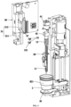
- FIG. 1 shows a schematic structural diagram of a microfluidic control detection system for a refrigerator according to an embodiment of the present application
- FIG.2 shows a schematic structural diagram of internal structure of a microfluidic control detection system according to an embodiment of the present application
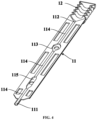
- FIG.3 shows a partial schematic exploded view of a microfluidic control detection system according to an embodiment of the present application.
- FIG.1 to FIG.3 also show a sample cup 2.
- the microfluidic control detection system 1 in the present application comprises a microfluidic biochip 10, a sample liquid driving device 40, and a detection mechanism 20.
- FIG.4 shows a schematic sectional view of a microfluidic biochip according to an embodiment of the present application.
- the microfluidic biochip 10 comprises a chip body 11 and an elastic airbag section 12.
- the chip body 11 comprises an inlet 111, a suction port 112, and a detection pool 113 formed inside the microfluidic biochip 10.
- the inlet 111, detection pool 113, and suction port 112 are sequentially interconnected through microchannels 114, thus forming a main channel.
- the elastic airbag section 12 is hermetically connected to the suction port 112.
- the sample liquid driving device 40 is configured to compress and release the elastic airbag section 12 under control of the microfluidic biochip 10, prompting sample liquid in contact with the inlet 111 to enter the microchannels 114 and flow towards the detection pool 113 via the microchannels 114.
- the detection mechanism 20 is configured to detect the detection pool 113 to obtain preset detection parameters of the sample liquid. Specifically, detection reagents can be placed in the detection pool 113, so that after a reaction of the sample liquid with the detection reagents inside the detection pool 113, the detection mechanism 20 performs detection on the detection pool 113.
- the microfluidic control detection system 1 of the present application comprises a microfluidic biochip 10, with the microfluidic biochip 10 comprising a chip body 11 and an elastic airbag section 12.
- the elastic airbag section 12 is hermetically connected to a suction port 112 of the chip body 11, thereby forming a closed space within the microfluidic biochip 10, with only an inlet 111 of the chip body 11 remaining an opening for sample introduction.
- a sample liquid driving device 40 expels air from inside the chip body 11 by compressing the elastic airbag section 12.
- the elastic airbag section 12 When the sample liquid driving device 40 releases the elastic airbag section 12, the elastic airbag section 12 returns to its original shape, prompting sample liquid in contact with inlet 111 to enter a detection pool 113 within the chip body 11 and react with the detection reagents inside the detection pool 113. Furthermore, repeated compression and release of the elastic airbag section 12 by the sample liquid driving device 40 ensure thorough mixing of sample liquid with detection reagents, enhancing accuracy of detection results.
- a microfluidic biochip 10 of the present application is specially designed with an elastic airbag section 12, eliminating a need for connecting pipelines between a sample liquid driving device 40 and a microfluidic biochip 10.
- Simple mechanical compression can be implemented, controlling suction volume and exhaust volume by adjusting deformation of the elastic airbag section 12, not only resolving air tightness issues between the sample liquid driving device 40 and the microfluidic biochip 10 but also maintaining precise control of sample introduction.
- the microfluidic control detection system when used for detecting different preset detection parameters, the specific choices of the microfluidic biochip 10 and the detection mechanism 20 might also vary.
- the microfluidic biochip 10 it contains could be a microfluidic pesticide detection chip capable of providing conditions for pesticide liquid detection
- the detection mechanism 20 it contains could be a pesticide detection mechanism capable of detecting pesticide parameters in the pesticide liquid.
- the chip body 11 further comprises a reaction pool 115 formed inside it.
- the reaction pool 115 is located on the main channel formed by sequentially connecting the inlet 111, the detection pool 113, and the suction port 112 and is connected between the inlet 111 and the detection pool 113, allowing sample liquid to react with reaction reagents in the reaction pool 115 before flowing into the detection pool 113.
- the reaction pool 115 is connected to the inlet 111 through microchannels 114, and also connected to the detection pool 113 through microchannels 114.
- the reaction reagent and detection reagent used for pesticide detection can be enzyme reagents and chromogenic agents, respectively.
- the reaction pool 115 is used for sample liquid to react with the enzyme reagent inside the reaction pool 115; the sample liquid that has reacted with the enzyme reagent flows into the detection pool 113 and reacts with the chromogenic agent in the detection pool 121.
- the detection mechanism 20 can be selected as a photoelectric detection mechanism, which may comprise structures such as a light source, a photosensitive element, a heating plate, and a thermostat.
- the chip body 11 and the elastic airbag section 12 are integrally formed by blow molding, which means the microfluidic biochip 10 is a single component, with the chip body 11 and the elastic airbag section 12 merely being two different parts of the microfluidic biochip 10, requiring no connection between them.
- microfluidic biochip 10 itself does not have any air tightness issues, meaning addition of the elastic airbag section 12 does not introduce air tightness problems to the microfluidic biochip 10 itself, thereby completely eliminating a series of adverse effects caused by air tightness issues to the microfluidic control detection system 1.
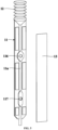
- FIG.5 shows a schematic exploded view of the microfluidic biochip according to an embodiment of the invention. Since the chip body 11 and elastic airbag section 12 are integrally formed by blow molding, it could be inconvenient to pre-add detection reagents into the detection pool 113 formed within the chip body 11. Therefore, in some embodiments, after chip body 11 and elastic airbag section 12 are formed by blow molding, a reagent adding hole 116 can be positioned on a side surface 11a of the chip body 11, connecting to the detection pool 113, allowing for addition of detection reagents into the detection pool 113 through the reagent adding hole 116.
- reaction reagents can be added to the reaction pool 115 in a similar manner (i.e., positioning a reagent adding hole 117 on a side surface of the chip body 11 connecting to the reaction pool 115).
- both reagent adding holes can be located on a same side surface of chip body 11, facilitating the sealing of the both reagent adding holes.
- the microfluidic biochip 10 comprises a sealing patch 13 hermetically attached to a side surface 11a of the chip body 11 (e.g., the side surface with the reagent adding holes), to seal one reagent adding hole 116 and another reagent adding hole 117.
- the aforementioned side surface 11a of chip body 11 can be parallel to a width direction of the chip body 11 and a length direction of the chip body 11. This is because surface area of the side surface parallel to the width direction of the chip body 11 and the length direction of chip body 11 is relatively large, making it easier to form a larger bonding surface between the chip body 11 and the sealing patch 13, thereby enhancing the seal between the chip body 11 and the sealing patch 13.
- the attachment of the chip body 11 to the sealing patch 13 is completed before installation of the microfluidic biochip 10, there are no constraints on operational space and sealing methods, thus effective and good sealing between the chip body 11 and the sealing patch 13 can be achieved.
- material for the chip body 11 and material for the elastic airbag section 12, as well as a shape of elastic airbag section 12, are configured to allow the elastic airbag section 12 to return to its original shape under its own elastic deformation recovery force after the sample liquid driving device 40 releases the elastic airbag section 12.
- the elastic airbag section 12 is configured as a threaded shape or a wavy shape extending along the length direction of chip body 11.
- the sample liquid driving device 40 is configured to apply a compressive force to the elastic airbag section 12 parallel to an extension direction of the elastic airbag section 12 under the control of the microfluidic biochip 10, inducing elastic deformation of the elastic airbag section 12 along the extension direction of the elastic airbag section 12. That is, a direction of the compressive force applied by the sample liquid driving device 40 to the elastic airbag section 12 is consistent with the extension direction of the elastic airbag section 12.
- the elastic airbag section 12 can elastically contract along the length direction of the chip body 11 under compression by the sample liquid driving device 40, and after release of the elastic airbag section 12 by the sample liquid driving device 40, the elastic airbag section 12 can return to its original state by relying on its own elasticity.
- the elastic airbag section 12 is configured to be a threaded tube or a corrugated tube extending along the length direction of chip body 11.
- the inlet 111 is located at a bottom of the chip body 11, and the elastic airbag section 12 is positioned at a top of the chip body 11.
- the sample liquid driving device 40 is situated above the microfluidic biochip 10 and is configured to compress the elastic airbag section 12 downwards under the control of the microfluidic biochip 10. This means, after the microfluidic biochip 10 is installed, the length direction of chip body 11 is vertical, which facilitates not only contact of inlet 111 with sample liquid but also arrangement of the sample liquid driving device 40.
- the microfluidic control detection system 1 comprises a chip installation mechanism 30.
- the applicants recognized that since there are no air tightness issues between the microfluidic biochip 10 and the sample liquid driving device 40, there is no need to consider the sealing docking structure between the microfluidic biochip 10 and the sample liquid driving device 40 during the installation of microfluidic biochip 10. It is only necessary to ensure that the microfluidic biochip 10 remains stable and reliable once installed. Therefore, it is no need to configure the chip installation mechanism 30 of the present application as a very complex structure, as long as it can hold the microfluidic biochip 10 securely.
- the chip installation mechanism 30 of the present application comprises an installation slot 31 configured to house the microfluidic biochip 10.
- the microfluidic biochip 10 is configured to be inserted into the installation slot 31 through a notch of the installation slot 31, not only achieving effective installation of the microfluidic biochip 10 but also significantly simplifying a structure of microfluidic control detection system 1.
- the inlet 111 of the chip body 11 is positioned outside of the installation slot 31 to facilitate introduction of sample liquid by inlet 111 when the microfluidic biochip 10 is in its installed state.
- the inlet 111 is located at a bottom of the chip body 11, and the elastic airbag section 12 is positioned at a top of chip body 11. Given that the elastic airbag section 12 is elastically deformable, it is impractical to install the microfluidic biochip 10 from the bottom up.
- the installation slot 31 of the present application is further configured to extend vertically, with the microfluidic biochip 10 configured to be inserted into the installation slot 31 in a direction parallel to a horizontal plane. That is, the elastic airbag section 12 is installed parallel to the chip body 11, with the elastic airbag section 12 not causing any obstruction or impact on assembly of the chip body 11. Meanwhile, structure configuration of the installation slot 31 allows only the chip body 11 to remain stationary within the installation slot 31, permitting the elastic airbag section 12 to deform elastically within the installation slot 31 without any hindrance.
- the installation slot 31 comprises a first slot section 311 for housing the chip body 11 and a second slot section 312 for housing the elastic airbag section 12, with the first slot section 311 located below the second slot section 312.
- a size of the first slot section 311 is smaller than a size of the second slot section 312, forming a step-like section 32 at a junction between the first slot section 311 and the second slot section 312.
- a bottom of the elastic airbag section 12 rests against the step-like section 32, preventing the microfluidic biochip 10 from falling downwards.
- the present application achieves vertical positioning of the microfluidic biochip 10 by configuring the installation slot 31 with simple structural dimensions, which simplify a positioning structure between the microfluidic biochip 10 and the installation slot 31.
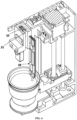
- FIG.6 shows a schematic sectional view of a microfluidic control detection system in a partial exploded state according to an embodiment of the present application.
- the chip installation mechanism 30 comprises at least one clamping component 33 positioned within the installation slot 31.
- the clamping component 33 is configured to secure the chip body 11 after the microfluidic biochip 10 is inserted into the installation slot 31, preventing the microfluidic biochip 10 from tilting, swaying, or dislodging from the installation slot 31 during a compression process or a release process of the elastic airbag section 12 by the sample liquid driving device 40, thereby limiting a movement of the microfluidic biochip 10 in a horizontal direction.
- an accommodation space for housing the clamping component 33 can be configured within the installation slot 31, with the clamping component 33 confined to the accommodation space and capable of elastic deformation within a certain range, maintaining optimal clamping force on the chip body 11.
- the clamping component 33 can comprise two symmetrically arranged and spaced apart claws 331.
- the two claws 331 are configured to apply opposing elastic forces (e.g., which are toward to each other) to two opposite side surfaces of the chip body 11 after the microfluidic biochip 10 is installed into the installation slot 31, thereby maintaining the microfluidic biochip 10 more stably.
- the sample liquid driving device 40 comprises a drive motor 41 and a push rod 42.
- the push rod 42 is connected to the drive motor 41, and the push rod 42 is configured to translate along an output shaft of the drive motor 41 when the drive motor 41 rotates.
- the output shaft of the drive motor 41 could be parallel to an extension direction of the elastic airbag section 12, to use the push rod 42 to compress the elastic airbag section 12 or release the elastic airbag section 12 when the drive motor 41 rotates.
- the microfluidic control detection system 1 comprises a weighing platform 81 and a bracket 82.
- the weighing platform 81 is fixedly set on a support frame 83 and configured to measure a weight of a sample contained in a sample cup 2 placed on it. It is understandable that the weighing platform 81 can measure combined weight of the sample cup 2 and the sample contained therein, subtracting a weight of the sample cup 2 itself to obtain the weight of the sample.
- the weighing platform 81 can also be configured to directly detect the weight of the sample contained in the sample cup 2, such as through tare measurement.
- the bracket 82 is configured to move in a controlled manner or operable manner, driving the sample cup 2 to move to a highest position where the sample liquid in the sample cup 2 can contact the inlet 111 of the microfluidic biochip 10.
- the microfluidic control detection system 1 comprises a buffer solution bottle 51 and a buffer solution driving device 52.
- the buffer solution bottle 51 is configured to contain a buffer solution.
- the buffer solution driving device 52 connected to the buffer solution bottle 51 is controlled to drive the buffer solution from the buffer solution bottle 51 into a sample cup 2 on the weighing platform 81. Mixture of buffer solution and sample in the sample cup 2 produces sample liquid.
- the buffer solution driving device 84 can be a peristaltic pump, diaphragm pump, or another suitable type of driving device.
- the microfluidic control detection system 1 comprises a housing 90.
- the housing 90 has an operation platform open towards a front side of the housing 90, with the weighing platform 81 at least partially located within the operation platform, facilitating users implement operations such as placing the sample cup 2 to or removing the sample cup 2 from the operation platform.
- the microfluidic control detection system 1 of the present application specially comprises a weighing platform 81 fixed on a support frame 83 and a bracket 82 capable of moving the sample cup 2.
- a weighing platform 81 fixed on a support frame 83 and a bracket 82 capable of moving the sample cup 2.
- the buffer solution driving device 52 adds an appropriate amount of buffer solution to the sample cup 2, and the bracket 82 automatically moves the sample cup 2 to the microfluidic biochip 10 for sample addition, making the sampling operation convenient, time-saving, and labor-saving, leading to a good user experience.
- the weighing platform 81 of the present application is fixed and does not move with movement of the bracket 82, the movement of the bracket 82 does not affect weighing accuracy of the weighing platform 81, ensuring high-precision measurement of the sample's weight, thereby improving accuracy of detection results from the microfluidic biochip 10.
- the bracket 82 when the sample cup 2 is weighed on the weighing platform 81, the bracket 82 should be completely detached from and not touch the sample cup 2 to avoid affecting weighing of the sample. After the weight of the sample has been measured, the bracket 82 needs to hold the sample cup 2 to move it together. That is, the bracket 82 needs to have two states: releasing the sample cup and holding the sample cup, and it should be able to automatically switch between these two states according to a detection process. To achieve an object of switching between the two states, the common design approach before the present application was to equip the bracket with a clamping mechanism, which automatically switches between releasing the sample cup and holding the sample cup through control of the clamping mechanism's action.
- the clamping mechanism increases structural complexity of the bracket and requires reserved space for action switches of the clamping mechanism to avoid interference or collision with other structures, which would increase volume of the microfluidic control detection system, making it unsuitable for refrigerators with limited space.
- the holding of the sample cup, especially the release of the sample cup needs to be highly synchronized with the detection process. That is, when the weighing platform needs to measure the weight of the sample, the clamping mechanism must be in a state of releasing the sample cup; only after the weighing platform has measured, the weight of the sample can the clamping mechanism hold the sample cup.
- the bracket 82 is set above the weighing platform 81 and comprises an annular frame 821 that is fitted outside the sample cup 2.
- the bracket 82 is configured to move controllably or operably in an up and down direction, using the annular frame 821 to lift the sample cup 2 off the weighing platform 81 as it moves upwards, and during its downward movement to a lowest position, it allows the sample cup 2 to be supported on the weighing platform 81 and uses an abutting effect between the sample cup 2 and the weighing platform 81 to detach the sample cup 2 from the annular frame 821.
- bracket 82 moves upwards, the annular frame 821 naturally lifts the sample cup 2 off the weighing platform 81; when the bracket 82 moves down to a certain position, the sample cup 2 is supported on the weighing platform 81, and as the bracket 82 continues to move down to the lowest position, the abutting effect between the sample cup 2 and the weighing platform 81 causes the sample cup 2 to detach from the annular frame 821, thus, the bracket 82 does not affect weight measurement of the sample in any way. It is clear that the bracket 82 of the present application naturally switches between lifting and releasing the sample cup 2 during its lifting process, without needs for any lifting control programs or releasing control programs, making a structure of the bracket 82 simple, as well as control logic of the bracket 82.
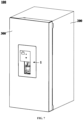
- the present application also introduces a refrigerator, as illustrated in FIG.7 , illustrating a schematic structural diagram of a refrigerator according to an embodiment of the present application.
- the refrigerator 100 incorporates the microfluidic control detection system 1 involved in any of the aforementioned embodiments, integrating the microfluidic control detection system 1 with the refrigerator 100. Given high frequency of use of refrigerators 100 in daily life and their primary function for storing food ingredients, integrating the microfluidic control detection system 1 into the refrigerator 100 facilitates users in conducting detection operations on food ingredient samples using the microfluidic control detection system 1.
- the present application fully leverages a storage function of the refrigerator 100, making a detection process more convenient. It also facilitates the interlinked control between the microfluidic control detection system 1 and the refrigerator 100, achieving a high level of intelligence that meets needs of smart homes.
- the refrigerator 100 comprises a cabinet 200 and a door 300.
- the cabinet 200 defines a storage space
- the door 300 is connected to the cabinet 200 to open and/or close the storage space.
- the microfluidic control detection system 1 is mounted on the door 300, which is not only convenient for operation but also does not occupy an original storage space inside the cabinet 200, thus not affecting storage capacity of the refrigerator 100 itself.
- the refrigerator 100 mentioned in the present application is broadly defined to include not only the conventional narrow sense of refrigerators but also storage devices with refrigeration, freezing, or other storage functions, such as refrigeration boxes, freezers, etc.
Landscapes
- Chemical & Material Sciences (AREA)
- Engineering & Computer Science (AREA)
- Health & Medical Sciences (AREA)
- Mechanical Engineering (AREA)
- Physics & Mathematics (AREA)
- Thermal Sciences (AREA)
- General Engineering & Computer Science (AREA)
- Dispersion Chemistry (AREA)
- Combustion & Propulsion (AREA)
- Analytical Chemistry (AREA)
- General Health & Medical Sciences (AREA)
- Hematology (AREA)
- Clinical Laboratory Science (AREA)
- Chemical Kinetics & Catalysis (AREA)
- Apparatus Associated With Microorganisms And Enzymes (AREA)
- Automatic Analysis And Handling Materials Therefor (AREA)
Abstract
Description
- The application claims priority from
Chinese Patent Application No. 202111414254.4, filed November 25, 2021 - The present application relates to the field of refrigeration technology, and more particularly to a microfluidic control detection system and refrigerator.
- With the improvement of living standards, there is often a need in daily life to detect residues, viruses, nutritional elements, or other aspects of food ingredients either qualitatively or quantitatively. For instance, due to the misuse of pesticides, the fruits, vegetables, and agricultural products we buy daily may contain excessive levels of residues. If the excessive levels of residues in these foods are not discovered in time, ingestion can cause significant harm to the human body. Moreover, the currently advocated breastfeeding is best for infants only when the breast milk has normal nutritional value. However, illnesses, medication, surgery, or other situations of the nursing mother may lead to reduced nutritional element content in the secreted milk or even the presence of viruses, thereby affecting the infant's growth and health. The functionality of existing household appliances is relatively singular, and when there is a need to detect residues, viruses, nutritional elements, or other aspects of food ingredients, it necessitates the separate purchase of a dedicated detection device. This leads to a multitude of household appliances and types, occupying significant space, and does not align with the development trend of smart homes.
- Among many detection methods, the use of microfluidic biochips for detection is relatively quick and compact, suitable for home use. To facilitate fluid movement within the chip, there are generally two methods: air pressure propulsion and centrifugal force propulsion. Centrifugal force propulsion relies on rotating centrifugal force to move droplets, which can only adjust unidirectional flow actions by adjusting the rotation speed. Air pressure propulsion utilizes positive air pressure and negative air pressure to bidirectionally propel fluid movement within the chip, offering high precision and controllability. However, when a suction port of the chip and a suction pipe of a pushing mechanism are connected, air tightness can be unstable and unreliable due to insufficient pressing area, uneven pressing surface, insufficient pressing force, inadequate precision of the syringe pump piston, and other reasons. To date, air tightness of air pressure propulsion remains an unsolved technical challenge.
- An object of a first aspect of the present application is to overcome at least one deficiency of the existing technology by providing a microfluidic control detection system for refrigerators that offers improved sealing performance and precise sample introduction control.
- A further object of a first aspect of the present application is to completely eliminate a series of adverse effects caused by air tightness issues.
- An object of a second aspect of the present application is to provide a refrigerator equipped with the aforementioned microfluidic control detection system.
- In accordance with a first aspect of the present application, the present application provides a microfluidic control detection system for a refrigerator, comprising:
- a microfluidic biochip, comprising a chip body and an elastic airbag section, where the chip body comprising an inlet, a suction port, and a detection pool formed inside, and the inlet, the detection pool, and the suction port are sequentially interconnected through microchannels, with the elastic airbag section hermetically connected to the suction port;
- a sample liquid driving device, configured to compress and release the elastic airbag section under control of the microfluidic biochip, prompting sample liquid in contact with the inlet to enter the microchannels and flow towards the detection pool via the microchannels; and
- a detection mechanism, configured to detect the detection pool to obtain preset detection parameters of the sample liquid; wherein,
- the chip body and the elastic airbag section are integrally formed by blow molding.
- In an embodiment of the present application, a reagent adding hole is positioned on a side surface of the chip body, connecting to the detection pool, allowing for addition of detection reagents into the detection pool through the reagent adding hole; and
the microfluidic biochip comprises a sealing patch hermetically attached to a side surface of the chip body to seal the reagent adding hole. - In an embodiment of the present application, the elastic airbag section is configured as a threaded shape or a wavy shape extending along a length direction of the chip body; and
the sample liquid driving device is configured to apply a compressive force to the elastic airbag section parallel to an extension direction of the elastic airbag section under the control of the microfluidic biochip, inducing elastic deformation of the elastic airbag section along the extension direction of the elastic airbag section. - In an embodiment of the present application, the inlet is located at a bottom of the chip body, and the elastic airbag section is positioned at a top of the chip body; and
the sample liquid driving device is situated above the microfluidic biochip and is configured to compress the elastic airbag section downwards under the control of the microfluidic biochip. - In an embodiment of the present application, the microfluidic control detection system further comprising:
- a chip installation mechanism, comprising an installation slot configured to house the microfluidic biochip; and
- the microfluidic biochip is configured to be inserted into the installation slot through a notch of the installation slot, with the inlet of the chip body positioned outside of the installation slot.
- In an embodiment of the present application, the inlet is located at a bottom of the chip body, and the elastic airbag section is positioned at a top of the chip body; and
the installation slot is configured to extend vertically, and the microfluidic biochip is configured to be inserted into the installation slot in a direction parallel to a horizontal plane. - In an embodiment of the present application, the installation slot comprises a first slot section for housing the chip body and a second slot section for housing the elastic airbag section, with a size of the first slot section smaller than a size of the second slot section, forming a step-like section at a junction between the first slot section and the second slot section; and
a bottom of the elastic airbag section rests against the step-like section. - In an embodiment of the present application, the chip installation mechanism comprises at least one clamping component positioned within the installation slot, which is configured to secure the chip body after the microfluidic biochip is inserted into the installation slot.
- In an embodiment of the present application, the clamping component comprises two symmetrically arranged and spaced apart claws, configured to apply opposing elastic forces to two opposite side surfaces of the chip body after the microfluidic biochip is installed into the installation slot.
- In accordance with a second aspect of the present application, the present application provides a refrigerator, comprising the microfluidic control detection system according to any of the aforementioned technical solutions.
- The microfluidic control detection system of the present application comprises a microfluidic biochip, with the microfluidic biochip comprising a chip body and an elastic airbag section. The elastic airbag section is hermetically connected to a suction port of the chip body, thereby forming a closed space within the microfluidic biochip, with only an inlet of the chip body remaining an opening for sample introduction. A sample liquid driving device expels air from inside the chip body by compressing the elastic airbag section. When the sample liquid driving device releases the elastic airbag section, the elastic airbag section returns to its original shape, prompting sample liquid in contact with inlet to enter a detection pool within the chip body. A microfluidic biochip of the present application is specially designed with an elastic airbag section, eliminating a need for connecting pipelines between a sample liquid driving device and a microfluidic biochip. Simple mechanical compression can be implemented, controlling suction volume and exhaust volume by adjusting deformation of the elastic airbag section, not only resolving air tightness issues between the sample liquid driving device and the microfluidic biochip but also maintaining precise control of sample introduction.
- Furthermore, the chip body and the elastic airbag section are integrally formed by blow molding, which means the microfluidic biochip is a single component, with the chip body and the elastic airbag section merely being two different parts of the microfluidic biochip, requiring no connection between them. Thus, microfluidic biochip itself does not have any air tightness issues, meaning addition of the elastic airbag section does not introduce air tightness problems to the microfluidic biochip itself, thereby completely eliminating a series of adverse effects caused by air tightness issues to the microfluidic control detection system.
- The present application integrates the microfluidic control detection system into a refrigerator, fully leveraging a storage function of the refrigerator to make a detection process more convenient and facilitating linked control between the microfluidic control detection system and the refrigerator. This higher level of automation meets the needs of smart homes.
- Further details and the advantages and features of the present application will become clearer to those skilled in art from the detailed description of the specific embodiments in conjunction with the accompanying drawings below.
- The subsequent text will describe some specific embodiments of the present application in a detailed but non-limiting manner with reference to drawings. The same reference numerals in the drawings denote the same or similar parts or components. It should be understood by those skilled in the art that these drawings are not necessarily drawn to scale. In the drawings:
-
FIG. 1 shows a schematic structural diagram of a microfluidic control detection system for a refrigerator according to an embodiment of the present application. -
FIG.2 shows a schematic structural diagram of internal structure of a microfluidic control detection system according to an embodiment of the present application. -
FIG.3 shows a partial schematic exploded view of a microfluidic control detection system according to an embodiment of the present application. -
FIG.4 shows a schematic sectional view of a microfluidic biochip according to an embodiment of the present application. -
FIG.5 shows a schematic exploded view of a microfluidic biochip according to an embodiment of the present application. -
FIG.6 shows a schematic sectional view of a microfluidic control detection system in a partial exploded state according to an embodiment of the present application. -
FIG.7 shows a schematic structural diagram of a refrigerator according to an embodiment of the present application. - The present application initially provides a microfluidic control detection system for a refrigerator. The microfluidic control detection system of the present application is configured for the qualitative or quantitative detection of preset detection parameters of sample liquids. These preset detection parameters could include parameters indicating whether the amount of pesticide residue exceeds standards and/or the specific numerical value of the pesticide residue, parameters indicating whether nutritional elements meet standards and/or the specific content of nutritional elements, parameters for indicating whether specific harmful substances (such as specific viruses) exceed standards and/or specific content of specific harmful substances, among others.
-
FIG. 1 shows a schematic structural diagram of a microfluidic control detection system for a refrigerator according to an embodiment of the present application,FIG.2 shows a schematic structural diagram of internal structure of a microfluidic control detection system according to an embodiment of the present application, andFIG.3 shows a partial schematic exploded view of a microfluidic control detection system according to an embodiment of the present application. For ease of understanding,FIG.1 to FIG.3 also show asample cup 2. - Referring to
FIG. 1 to FIG.3 , the microfluidiccontrol detection system 1 in the present application comprises amicrofluidic biochip 10, a sampleliquid driving device 40, and adetection mechanism 20. -
FIG.4 shows a schematic sectional view of a microfluidic biochip according to an embodiment of the present application. Themicrofluidic biochip 10 comprises achip body 11 and anelastic airbag section 12. Thechip body 11 comprises aninlet 111, asuction port 112, and adetection pool 113 formed inside themicrofluidic biochip 10. Theinlet 111,detection pool 113, andsuction port 112 are sequentially interconnected throughmicrochannels 114, thus forming a main channel. Theelastic airbag section 12 is hermetically connected to thesuction port 112. The sampleliquid driving device 40 is configured to compress and release theelastic airbag section 12 under control of themicrofluidic biochip 10, prompting sample liquid in contact with theinlet 111 to enter themicrochannels 114 and flow towards thedetection pool 113 via themicrochannels 114. Thedetection mechanism 20 is configured to detect thedetection pool 113 to obtain preset detection parameters of the sample liquid. Specifically, detection reagents can be placed in thedetection pool 113, so that after a reaction of the sample liquid with the detection reagents inside thedetection pool 113, thedetection mechanism 20 performs detection on thedetection pool 113. - The microfluidic
control detection system 1 of the present application comprises amicrofluidic biochip 10, with themicrofluidic biochip 10 comprising achip body 11 and anelastic airbag section 12. Theelastic airbag section 12 is hermetically connected to asuction port 112 of thechip body 11, thereby forming a closed space within themicrofluidic biochip 10, with only aninlet 111 of thechip body 11 remaining an opening for sample introduction. A sampleliquid driving device 40 expels air from inside thechip body 11 by compressing theelastic airbag section 12. When the sampleliquid driving device 40 releases theelastic airbag section 12, theelastic airbag section 12 returns to its original shape, prompting sample liquid in contact withinlet 111 to enter adetection pool 113 within thechip body 11 and react with the detection reagents inside thedetection pool 113. Furthermore, repeated compression and release of theelastic airbag section 12 by the sampleliquid driving device 40 ensure thorough mixing of sample liquid with detection reagents, enhancing accuracy of detection results. - A
microfluidic biochip 10 of the present application is specially designed with anelastic airbag section 12, eliminating a need for connecting pipelines between a sampleliquid driving device 40 and amicrofluidic biochip 10. Simple mechanical compression can be implemented, controlling suction volume and exhaust volume by adjusting deformation of theelastic airbag section 12, not only resolving air tightness issues between the sampleliquid driving device 40 and themicrofluidic biochip 10 but also maintaining precise control of sample introduction. - It is understandable to those skilled in art that when the microfluidic control detection system is used for detecting different preset detection parameters, the specific choices of the
microfluidic biochip 10 and thedetection mechanism 20 might also vary. For example, when the microfluidic control detection system is used for pesticide residue detection, themicrofluidic biochip 10 it contains could be a microfluidic pesticide detection chip capable of providing conditions for pesticide liquid detection, and thedetection mechanism 20 it contains could be a pesticide detection mechanism capable of detecting pesticide parameters in the pesticide liquid. - In a specific embodiment, when the
detection mechanism 20 is a pesticide detection mechanism for detecting pesticide parameters in pesticide liquid, a quick qualitative detection of whether pesticide residue in sample liquid exceeds standards can be conducted using the enzyme inhibition rate method. In this case, thechip body 11 further comprises areaction pool 115 formed inside it. Thereaction pool 115 is located on the main channel formed by sequentially connecting theinlet 111, thedetection pool 113, and thesuction port 112 and is connected between theinlet 111 and thedetection pool 113, allowing sample liquid to react with reaction reagents in thereaction pool 115 before flowing into thedetection pool 113. Thereaction pool 115 is connected to theinlet 111 throughmicrochannels 114, and also connected to thedetection pool 113 throughmicrochannels 114. The reaction reagent and detection reagent used for pesticide detection can be enzyme reagents and chromogenic agents, respectively. Thereaction pool 115 is used for sample liquid to react with the enzyme reagent inside thereaction pool 115; the sample liquid that has reacted with the enzyme reagent flows into thedetection pool 113 and reacts with the chromogenic agent in the detection pool 121. Thedetection mechanism 20 can be selected as a photoelectric detection mechanism, which may comprise structures such as a light source, a photosensitive element, a heating plate, and a thermostat. - In some embodiments, the
chip body 11 and theelastic airbag section 12 are integrally formed by blow molding, which means themicrofluidic biochip 10 is a single component, with thechip body 11 and theelastic airbag section 12 merely being two different parts of themicrofluidic biochip 10, requiring no connection between them. Thus,microfluidic biochip 10 itself does not have any air tightness issues, meaning addition of theelastic airbag section 12 does not introduce air tightness problems to themicrofluidic biochip 10 itself, thereby completely eliminating a series of adverse effects caused by air tightness issues to the microfluidiccontrol detection system 1. -
FIG.5 shows a schematic exploded view of the microfluidic biochip according to an embodiment of the invention. Since thechip body 11 andelastic airbag section 12 are integrally formed by blow molding, it could be inconvenient to pre-add detection reagents into thedetection pool 113 formed within thechip body 11. Therefore, in some embodiments, afterchip body 11 andelastic airbag section 12 are formed by blow molding, areagent adding hole 116 can be positioned on aside surface 11a of thechip body 11, connecting to thedetection pool 113, allowing for addition of detection reagents into thedetection pool 113 through thereagent adding hole 116. When areaction pool 115 is formed within thechip body 11, reaction reagents can be added to thereaction pool 115 in a similar manner (i.e., positioning areagent adding hole 117 on a side surface of thechip body 11 connecting to the reaction pool 115). Preferably, both reagent adding holes can be located on a same side surface ofchip body 11, facilitating the sealing of the both reagent adding holes. - Furthermore, the
microfluidic biochip 10 comprises a sealingpatch 13 hermetically attached to aside surface 11a of the chip body 11 (e.g., the side surface with the reagent adding holes), to seal onereagent adding hole 116 and anotherreagent adding hole 117. Preferably, theaforementioned side surface 11a ofchip body 11 can be parallel to a width direction of thechip body 11 and a length direction of thechip body 11. This is because surface area of the side surface parallel to the width direction of thechip body 11 and the length direction ofchip body 11 is relatively large, making it easier to form a larger bonding surface between thechip body 11 and the sealingpatch 13, thereby enhancing the seal between thechip body 11 and the sealingpatch 13. Moreover, since the attachment of thechip body 11 to the sealingpatch 13 is completed before installation of themicrofluidic biochip 10, there are no constraints on operational space and sealing methods, thus effective and good sealing between thechip body 11 and the sealingpatch 13 can be achieved. - It should be noted that material for the
chip body 11 and material for theelastic airbag section 12, as well as a shape ofelastic airbag section 12, are configured to allow theelastic airbag section 12 to return to its original shape under its own elastic deformation recovery force after the sampleliquid driving device 40 releases theelastic airbag section 12. - In some embodiments, the
elastic airbag section 12 is configured as a threaded shape or a wavy shape extending along the length direction ofchip body 11. The sampleliquid driving device 40 is configured to apply a compressive force to theelastic airbag section 12 parallel to an extension direction of theelastic airbag section 12 under the control of themicrofluidic biochip 10, inducing elastic deformation of theelastic airbag section 12 along the extension direction of theelastic airbag section 12. That is, a direction of the compressive force applied by the sampleliquid driving device 40 to theelastic airbag section 12 is consistent with the extension direction of theelastic airbag section 12. Theelastic airbag section 12 can elastically contract along the length direction of thechip body 11 under compression by the sampleliquid driving device 40, and after release of theelastic airbag section 12 by the sampleliquid driving device 40, theelastic airbag section 12 can return to its original state by relying on its own elasticity. - Specifically, the
elastic airbag section 12 is configured to be a threaded tube or a corrugated tube extending along the length direction ofchip body 11. - In some embodiments, the
inlet 111 is located at a bottom of thechip body 11, and theelastic airbag section 12 is positioned at a top of thechip body 11. The sampleliquid driving device 40 is situated above themicrofluidic biochip 10 and is configured to compress theelastic airbag section 12 downwards under the control of themicrofluidic biochip 10. This means, after themicrofluidic biochip 10 is installed, the length direction ofchip body 11 is vertical, which facilitates not only contact ofinlet 111 with sample liquid but also arrangement of the sampleliquid driving device 40. - In some embodiments, the microfluidic
control detection system 1 comprises achip installation mechanism 30. The applicants recognized that since there are no air tightness issues between themicrofluidic biochip 10 and the sampleliquid driving device 40, there is no need to consider the sealing docking structure between themicrofluidic biochip 10 and the sampleliquid driving device 40 during the installation ofmicrofluidic biochip 10. It is only necessary to ensure that themicrofluidic biochip 10 remains stable and reliable once installed. Therefore, it is no need to configure thechip installation mechanism 30 of the present application as a very complex structure, as long as it can hold themicrofluidic biochip 10 securely. - For an aforementioned purpose, the
chip installation mechanism 30 of the present application comprises aninstallation slot 31 configured to house themicrofluidic biochip 10. Themicrofluidic biochip 10 is configured to be inserted into theinstallation slot 31 through a notch of theinstallation slot 31, not only achieving effective installation of themicrofluidic biochip 10 but also significantly simplifying a structure of microfluidiccontrol detection system 1. - Further, the
inlet 111 of thechip body 11 is positioned outside of theinstallation slot 31 to facilitate introduction of sample liquid byinlet 111 when themicrofluidic biochip 10 is in its installed state. - In some embodiments, the
inlet 111 is located at a bottom of thechip body 11, and theelastic airbag section 12 is positioned at a top ofchip body 11. Given that theelastic airbag section 12 is elastically deformable, it is impractical to install themicrofluidic biochip 10 from the bottom up. - Therefore, the
installation slot 31 of the present application is further configured to extend vertically, with themicrofluidic biochip 10 configured to be inserted into theinstallation slot 31 in a direction parallel to a horizontal plane. That is, theelastic airbag section 12 is installed parallel to thechip body 11, with theelastic airbag section 12 not causing any obstruction or impact on assembly of thechip body 11. Meanwhile, structure configuration of theinstallation slot 31 allows only thechip body 11 to remain stationary within theinstallation slot 31, permitting theelastic airbag section 12 to deform elastically within theinstallation slot 31 without any hindrance. - In some embodiments, the
installation slot 31 comprises afirst slot section 311 for housing thechip body 11 and asecond slot section 312 for housing theelastic airbag section 12, with thefirst slot section 311 located below thesecond slot section 312. A size of thefirst slot section 311 is smaller than a size of thesecond slot section 312, forming a step-like section 32 at a junction between thefirst slot section 311 and thesecond slot section 312. A bottom of theelastic airbag section 12 rests against the step-like section 32, preventing themicrofluidic biochip 10 from falling downwards. Thus, the entiremicrofluidic biochip 10 can be supported within theinstallation slot 31, achieving vertical positioning ofmicrofluidic biochip 10. The present application achieves vertical positioning of themicrofluidic biochip 10 by configuring theinstallation slot 31 with simple structural dimensions, which simplify a positioning structure between themicrofluidic biochip 10 and theinstallation slot 31. -
FIG.6 shows a schematic sectional view of a microfluidic control detection system in a partial exploded state according to an embodiment of the present application. In some embodiments, thechip installation mechanism 30 comprises at least oneclamping component 33 positioned within theinstallation slot 31. Theclamping component 33 is configured to secure thechip body 11 after themicrofluidic biochip 10 is inserted into theinstallation slot 31, preventing themicrofluidic biochip 10 from tilting, swaying, or dislodging from theinstallation slot 31 during a compression process or a release process of theelastic airbag section 12 by the sampleliquid driving device 40, thereby limiting a movement of themicrofluidic biochip 10 in a horizontal direction. - Specifically, an accommodation space for housing the
clamping component 33 can be configured within theinstallation slot 31, with theclamping component 33 confined to the accommodation space and capable of elastic deformation within a certain range, maintaining optimal clamping force on thechip body 11. - Furthermore, the
clamping component 33 can comprise two symmetrically arranged and spaced apartclaws 331. The twoclaws 331 are configured to apply opposing elastic forces (e.g., which are toward to each other) to two opposite side surfaces of thechip body 11 after themicrofluidic biochip 10 is installed into theinstallation slot 31, thereby maintaining themicrofluidic biochip 10 more stably. - In some embodiments, the sample
liquid driving device 40 comprises adrive motor 41 and apush rod 42. Thepush rod 42 is connected to thedrive motor 41, and thepush rod 42 is configured to translate along an output shaft of thedrive motor 41 when thedrive motor 41 rotates. Specifically, the output shaft of thedrive motor 41 could be parallel to an extension direction of theelastic airbag section 12, to use thepush rod 42 to compress theelastic airbag section 12 or release theelastic airbag section 12 when thedrive motor 41 rotates. - In some embodiments, the microfluidic
control detection system 1 comprises a weighingplatform 81 and abracket 82. The weighingplatform 81 is fixedly set on asupport frame 83 and configured to measure a weight of a sample contained in asample cup 2 placed on it. It is understandable that the weighingplatform 81 can measure combined weight of thesample cup 2 and the sample contained therein, subtracting a weight of thesample cup 2 itself to obtain the weight of the sample. The weighingplatform 81 can also be configured to directly detect the weight of the sample contained in thesample cup 2, such as through tare measurement. Thebracket 82 is configured to move in a controlled manner or operable manner, driving thesample cup 2 to move to a highest position where the sample liquid in thesample cup 2 can contact theinlet 111 of themicrofluidic biochip 10. - In some embodiments, the microfluidic
control detection system 1 comprises abuffer solution bottle 51 and a buffersolution driving device 52. Thebuffer solution bottle 51 is configured to contain a buffer solution. The buffersolution driving device 52 connected to thebuffer solution bottle 51, is controlled to drive the buffer solution from thebuffer solution bottle 51 into asample cup 2 on the weighingplatform 81. Mixture of buffer solution and sample in thesample cup 2 produces sample liquid. Specifically, the buffer solution driving device 84 can be a peristaltic pump, diaphragm pump, or another suitable type of driving device. - In some embodiments, the microfluidic
control detection system 1 comprises ahousing 90. Thehousing 90 has an operation platform open towards a front side of thehousing 90, with the weighingplatform 81 at least partially located within the operation platform, facilitating users implement operations such as placing thesample cup 2 to or removing thesample cup 2 from the operation platform. - The microfluidic
control detection system 1 of the present application specially comprises a weighingplatform 81 fixed on asupport frame 83 and abracket 82 capable of moving thesample cup 2. During detection, users only need to place thesample cup 2 on the weighingplatform 81, which measures the weight of the sample. The buffersolution driving device 52 adds an appropriate amount of buffer solution to thesample cup 2, and thebracket 82 automatically moves thesample cup 2 to themicrofluidic biochip 10 for sample addition, making the sampling operation convenient, time-saving, and labor-saving, leading to a good user experience. More importantly, since the weighingplatform 81 of the present application is fixed and does not move with movement of thebracket 82, the movement of thebracket 82 does not affect weighing accuracy of the weighingplatform 81, ensuring high-precision measurement of the sample's weight, thereby improving accuracy of detection results from themicrofluidic biochip 10. - Inventors recognized that when the
sample cup 2 is weighed on the weighingplatform 81, thebracket 82 should be completely detached from and not touch thesample cup 2 to avoid affecting weighing of the sample. After the weight of the sample has been measured, thebracket 82 needs to hold thesample cup 2 to move it together. That is, thebracket 82 needs to have two states: releasing the sample cup and holding the sample cup, and it should be able to automatically switch between these two states according to a detection process. To achieve an object of switching between the two states, the common design approach before the present application was to equip the bracket with a clamping mechanism, which automatically switches between releasing the sample cup and holding the sample cup through control of the clamping mechanism's action. However, the applicants recognized that this traditional design approach is outdated and has many drawbacks. For example, the clamping mechanism increases structural complexity of the bracket and requires reserved space for action switches of the clamping mechanism to avoid interference or collision with other structures, which would increase volume of the microfluidic control detection system, making it unsuitable for refrigerators with limited space. Moreover, the holding of the sample cup, especially the release of the sample cup, needs to be highly synchronized with the detection process. That is, when the weighing platform needs to measure the weight of the sample, the clamping mechanism must be in a state of releasing the sample cup; only after the weighing platform has measured, the weight of the sample can the clamping mechanism hold the sample cup. These requirements for timing precision of control of the clamping mechanism's state switching are very high. Any slight deviation or error accumulation could easily lead to disorder in the entire detection process and result in incorrect detection results. - To address this, the inventors attempted to break away from the traditional design approach and developed a completely new bracket structure. In some embodiments, the
bracket 82 is set above the weighingplatform 81 and comprises anannular frame 821 that is fitted outside thesample cup 2. Thebracket 82 is configured to move controllably or operably in an up and down direction, using theannular frame 821 to lift thesample cup 2 off the weighingplatform 81 as it moves upwards, and during its downward movement to a lowest position, it allows thesample cup 2 to be supported on the weighingplatform 81 and uses an abutting effect between thesample cup 2 and the weighingplatform 81 to detach thesample cup 2 from theannular frame 821. - That is, as the
bracket 82 moves upwards, theannular frame 821 naturally lifts thesample cup 2 off the weighingplatform 81; when thebracket 82 moves down to a certain position, thesample cup 2 is supported on the weighingplatform 81, and as thebracket 82 continues to move down to the lowest position, the abutting effect between thesample cup 2 and the weighingplatform 81 causes thesample cup 2 to detach from theannular frame 821, thus, thebracket 82 does not affect weight measurement of the sample in any way. It is clear that thebracket 82 of the present application naturally switches between lifting and releasing thesample cup 2 during its lifting process, without needs for any lifting control programs or releasing control programs, making a structure of thebracket 82 simple, as well as control logic of thebracket 82. - The present application also introduces a refrigerator, as illustrated in
FIG.7 , illustrating a schematic structural diagram of a refrigerator according to an embodiment of the present application. Therefrigerator 100 incorporates the microfluidiccontrol detection system 1 involved in any of the aforementioned embodiments, integrating the microfluidiccontrol detection system 1 with therefrigerator 100. Given high frequency of use ofrefrigerators 100 in daily life and their primary function for storing food ingredients, integrating the microfluidiccontrol detection system 1 into therefrigerator 100 facilitates users in conducting detection operations on food ingredient samples using the microfluidiccontrol detection system 1. - By integrating the microfluidic
control detection system 1 into therefrigerator 100, the present application fully leverages a storage function of therefrigerator 100, making a detection process more convenient. It also facilitates the interlinked control between the microfluidiccontrol detection system 1 and therefrigerator 100, achieving a high level of intelligence that meets needs of smart homes. - Additionally, the
refrigerator 100 comprises acabinet 200 and adoor 300. Thecabinet 200 defines a storage space, and thedoor 300 is connected to thecabinet 200 to open and/or close the storage space. Preferably, the microfluidiccontrol detection system 1 is mounted on thedoor 300, which is not only convenient for operation but also does not occupy an original storage space inside thecabinet 200, thus not affecting storage capacity of therefrigerator 100 itself. - The
refrigerator 100 mentioned in the present application is broadly defined to include not only the conventional narrow sense of refrigerators but also storage devices with refrigeration, freezing, or other storage functions, such as refrigeration boxes, freezers, etc. - It should be understood by those skilled in the art that the terms "up," "down," "front," "back," "top," "bottom," and other directional or positional terms used in the embodiments of the present application are based on an actual usage state of the microfluidic
control detection system 1 and therefrigerator 100. These terms are merely for the convenience of describing and understanding the technical solutions of the present application and should not be interpreted as limiting the present application to specific orientations or configurations. - Thus, it should be recognized by those skilled in art that although this document has thoroughly presented and described several exemplary embodiments of the present application, many other variations or modifications that are in accordance with the principles of the present application can be directly determined or derived from the content disclosed here without departing from the spirit and scope of the present application. Therefore, the scope of the present application should be understood and recognized to cover all such other variations or modifications.
Claims (10)
- A microfluidic control detection system for a refrigerator, comprising:a microfluidic biochip, comprising a chip body and an elastic airbag section, where the chip body comprising an inlet, a suction port, and a detection pool formed inside, and the inlet, the detection pool, and the suction port are sequentially interconnected through microchannels, with the elastic airbag section hermetically connected to the suction port;a sample liquid driving device, configured to compress and release the elastic airbag section under control of the microfluidic biochip, prompting sample liquid in contact with the inlet to enter the microchannels and flow towards the detection pool via the microchannels; anda detection mechanism, configured to detect the detection pool to obtain preset detection parameters of the sample liquid; wherein,the chip body and the elastic airbag section are integrally formed by blow molding.
- The microfluidic control detection system according to claim 1, wherein:a reagent adding hole is positioned on a side surface of the chip body, connecting to the detection pool, allowing for addition of detection reagents into the detection pool through the reagent adding hole; andthe microfluidic biochip comprises a sealing patch hermetically attached to a side surface of the chip body to seal the reagent adding hole.
- The microfluidic control detection system according to claim 1, wherein:the elastic airbag section is configured as a threaded shape or a wavy shape extending along a length direction of the chip body; andthe sample liquid driving device is configured to apply a compressive force to the elastic airbag section parallel to an extension direction of the elastic airbag section under the control of the microfluidic biochip, inducing elastic deformation of the elastic airbag section along the extension direction of the elastic airbag section.
- The microfluidic control detection system according to claim 3, wherein:the inlet is located at a bottom of the chip body, and the elastic airbag section is positioned at a top of the chip body; andthe sample liquid driving device is situated above the microfluidic biochip and is configured to compress the elastic airbag section downwards under the control of the microfluidic biochip.
- The microfluidic control detection system according to claims 1-4, further comprising:a chip installation mechanism, comprising an installation slot configured to house the microfluidic biochip; andthe microfluidic biochip is configured to be inserted into the installation slot through a notch of the installation slot, with the inlet of the chip body positioned outside of the installation slot.
- The microfluidic control detection system according to claim 5, wherein:the inlet is located at a bottom of the chip body, and the elastic airbag section is positioned at a top of the chip body; andthe installation slot is configured to extend vertically, and the microfluidic biochip is configured to be inserted into the installation slot in a direction parallel to a horizontal plane.
- The microfluidic control detection system according to claim 6, wherein:the installation slot comprises a first slot section for housing the chip body and a second slot section for housing the elastic airbag section, with a size of the first slot section smaller than a size of the second slot section, forming a step-like section at a junction between the first slot section and the second slot section; anda bottom of the elastic airbag section rests against the step-like section.
- The microfluidic control detection system according to claim 5, wherein:
the chip installation mechanism comprises at least one clamping component positioned within the installation slot, which is configured to secure the chip body after the microfluidic biochip is inserted into the installation slot. - The microfluidic control detection system according to claim 8, wherein:
the clamping component comprises two symmetrically arranged and spaced apart claws, configured to apply opposing elastic forces to two opposite side surfaces of the chip body after the microfluidic biochip is installed into the installation slot. - A refrigerator, comprising the microfluidic control detection system according to any one of claims 1-9.
Applications Claiming Priority (2)
| Application Number | Priority Date | Filing Date | Title |
|---|---|---|---|
| CN202111414254.4A CN116159606A (en) | 2021-11-25 | 2021-11-25 | Microfluidic detection system for refrigerator and refrigerator |
| PCT/CN2022/126154 WO2023093383A1 (en) | 2021-11-25 | 2022-10-19 | Microfluidic detection system for refrigerator, and refrigerator |
Publications (2)
| Publication Number | Publication Date |
|---|---|
| EP4438176A1 true EP4438176A1 (en) | 2024-10-02 |
| EP4438176A4 EP4438176A4 (en) | 2025-03-19 |
Family
ID=86415071
Family Applications (1)
| Application Number | Title | Priority Date | Filing Date |
|---|---|---|---|
| EP22897466.3A Pending EP4438176A4 (en) | 2021-11-25 | 2022-10-19 | MICROFLUIDIC DETECTION SYSTEM FOR REFRIGERATOR, AND REFRIGERATOR |
Country Status (3)
| Country | Link |
|---|---|
| EP (1) | EP4438176A4 (en) |
| CN (1) | CN116159606A (en) |
| WO (1) | WO2023093383A1 (en) |
Families Citing this family (2)
| Publication number | Priority date | Publication date | Assignee | Title |
|---|---|---|---|---|
| CN117214453B (en) * | 2023-11-07 | 2024-04-05 | 长春迈克赛德医疗科技有限公司 | Sample suction needle system and sample suction method |
| CN118162227B (en) * | 2024-05-13 | 2024-08-02 | 至美时代生物智能科技(北京)有限公司 | Clamping device |
Family Cites Families (10)
| Publication number | Priority date | Publication date | Assignee | Title |
|---|---|---|---|---|
| CN102671729B (en) * | 2012-05-07 | 2014-04-16 | 博奥生物有限公司 | Micro-fluidic chip for multi-index biochemical detection |
| CN204514801U (en) * | 2015-04-01 | 2015-07-29 | 杭州霆科生物科技有限公司 | A kind of throwing type micro-fluidic chip for residues of pesticides Site Detection |
| CN107810060A (en) * | 2015-04-24 | 2018-03-16 | 美飒生物技术公司 | Fluid detection box |
| CN205731290U (en) * | 2015-12-23 | 2016-11-30 | 杭州霆科生物科技有限公司 | A kind of food safety detection micro-fluidic chip of pre-stored reaction reagent |
| CN207393445U (en) * | 2017-11-10 | 2018-05-22 | 威海波斯顿游艇股份有限公司 | A kind of manual-automatic integrated air charging system based on motorboat |
| CN208031626U (en) * | 2017-12-07 | 2018-11-02 | 李刚 | A kind of portable simple respirator |
| CN111175529A (en) * | 2020-01-23 | 2020-05-19 | 广州万孚生物技术股份有限公司 | In-vitro diagnosis analyzer, reagent card and mounting structure |
| CN212674733U (en) * | 2020-07-01 | 2021-03-09 | 江西远东生物科技有限公司 | Detection equipment for producing medical disposable mask |
| CN214039171U (en) * | 2020-09-27 | 2021-08-24 | 青岛海尔电冰箱有限公司 | Micro-fluidic detection system for refrigerator and refrigerator |
| CN214041434U (en) * | 2020-09-27 | 2021-08-24 | 青岛海尔电冰箱有限公司 | Micro-fluidic detection system for refrigerator and refrigerator |
-
2021
- 2021-11-25 CN CN202111414254.4A patent/CN116159606A/en active Pending
-
2022
- 2022-10-19 EP EP22897466.3A patent/EP4438176A4/en active Pending
- 2022-10-19 WO PCT/CN2022/126154 patent/WO2023093383A1/en not_active Ceased
Also Published As
| Publication number | Publication date |
|---|---|
| CN116159606A (en) | 2023-05-26 |
| WO2023093383A1 (en) | 2023-06-01 |
| EP4438176A4 (en) | 2025-03-19 |
Similar Documents
| Publication | Publication Date | Title |
|---|---|---|
| EP4438176A1 (en) | Microfluidic detection system for refrigerator, and refrigerator | |
| CN214039111U (en) | Refrigerator with a door | |
| CN214041434U (en) | Micro-fluidic detection system for refrigerator and refrigerator | |
| CN214039110U (en) | Refrigerator with a door | |
| CN214039171U (en) | Micro-fluidic detection system for refrigerator and refrigerator | |
| CN214039173U (en) | Micro-fluidic detection system for refrigerator and refrigerator | |
| CN214039172U (en) | A incomplete detecting system of farming and refrigerator for refrigerator | |
| WO2022062994A1 (en) | Microfluidic detection system, control method therefor, and refrigerator | |
| EP4407320A1 (en) | Microfluidic detection system for refrigerator, and refrigerator | |
| US20240399363A1 (en) | Microfluidic control detection system and refrigerator | |
| US12535496B2 (en) | Microfluidic detection system for refrigerator and refrigerator | |
| CN114324909B (en) | Microfluidic detection system for refrigerator and refrigerator | |
| CN114324904A (en) | Micro-fluidic detection system for refrigerator and refrigerator | |
| EP4206569B1 (en) | Refrigerator | |
| CN114324913B (en) | Microfluidic detection system for refrigerator and refrigerator | |
| WO2023093382A1 (en) | Microfluidic detection system for refrigerator, and refrigerator | |
| CN114324903A (en) | Micro-fluidic detection system for refrigerator, control method of micro-fluidic detection system and refrigerator | |
| CN218496895U (en) | Micro-fluidic detection system and refrigerator | |
| CN114324906A (en) | Micro-fluidic detection system, control method thereof and refrigerator |
Legal Events
| Date | Code | Title | Description |
|---|---|---|---|
| STAA | Information on the status of an ep patent application or granted ep patent |
Free format text: STATUS: THE INTERNATIONAL PUBLICATION HAS BEEN MADE |
|
| PUAI | Public reference made under article 153(3) epc to a published international application that has entered the european phase |
Free format text: ORIGINAL CODE: 0009012 |
|
| STAA | Information on the status of an ep patent application or granted ep patent |
Free format text: STATUS: REQUEST FOR EXAMINATION WAS MADE |
|
| 17P | Request for examination filed |
Effective date: 20240327 |
|
| AK | Designated contracting states |
Kind code of ref document: A1 Designated state(s): AL AT BE BG CH CY CZ DE DK EE ES FI FR GB GR HR HU IE IS IT LI LT LU LV MC ME MK MT NL NO PL PT RO RS SE SI SK SM TR |
|
| DAV | Request for validation of the european patent (deleted) | ||
| DAX | Request for extension of the european patent (deleted) | ||
| A4 | Supplementary search report drawn up and despatched |
Effective date: 20250218 |
|
| RIC1 | Information provided on ipc code assigned before grant |
Ipc: B01L 9/00 20060101ALI20250212BHEP Ipc: F25D 23/02 20060101ALI20250212BHEP Ipc: F25D 23/12 20060101ALI20250212BHEP Ipc: G01N 35/10 20060101ALI20250212BHEP Ipc: B01L 3/00 20060101AFI20250212BHEP |