EP4438099A1 - Guide wire - Google Patents
Guide wire Download PDFInfo
- Publication number
- EP4438099A1 EP4438099A1 EP22898265.8A EP22898265A EP4438099A1 EP 4438099 A1 EP4438099 A1 EP 4438099A1 EP 22898265 A EP22898265 A EP 22898265A EP 4438099 A1 EP4438099 A1 EP 4438099A1
- Authority
- EP
- European Patent Office
- Prior art keywords
- distal end
- joint part
- guide wire
- end joint
- core shaft
- Prior art date
- Legal status (The legal status is an assumption and is not a legal conclusion. Google has not performed a legal analysis and makes no representation as to the accuracy of the status listed.)
- Granted
Links
Images


Classifications
-
- A—HUMAN NECESSITIES
- A61—MEDICAL OR VETERINARY SCIENCE; HYGIENE
- A61M—DEVICES FOR INTRODUCING MEDIA INTO, OR ONTO, THE BODY; DEVICES FOR TRANSDUCING BODY MEDIA OR FOR TAKING MEDIA FROM THE BODY; DEVICES FOR PRODUCING OR ENDING SLEEP OR STUPOR
- A61M25/00—Catheters; Hollow probes
- A61M25/01—Introducing, guiding, advancing, emplacing or holding catheters
- A61M25/0105—Steering means as part of the catheter or advancing means; Markers for positioning
- A61M25/0108—Steering means as part of the catheter or advancing means; Markers for positioning using radio-opaque or ultrasound markers
-
- A—HUMAN NECESSITIES
- A61—MEDICAL OR VETERINARY SCIENCE; HYGIENE
- A61M—DEVICES FOR INTRODUCING MEDIA INTO, OR ONTO, THE BODY; DEVICES FOR TRANSDUCING BODY MEDIA OR FOR TAKING MEDIA FROM THE BODY; DEVICES FOR PRODUCING OR ENDING SLEEP OR STUPOR
- A61M25/00—Catheters; Hollow probes
- A61M25/01—Introducing, guiding, advancing, emplacing or holding catheters
- A61M25/09—Guide wires
-
- A—HUMAN NECESSITIES
- A61—MEDICAL OR VETERINARY SCIENCE; HYGIENE
- A61M—DEVICES FOR INTRODUCING MEDIA INTO, OR ONTO, THE BODY; DEVICES FOR TRANSDUCING BODY MEDIA OR FOR TAKING MEDIA FROM THE BODY; DEVICES FOR PRODUCING OR ENDING SLEEP OR STUPOR
- A61M25/00—Catheters; Hollow probes
- A61M25/01—Introducing, guiding, advancing, emplacing or holding catheters
- A61M25/09—Guide wires
- A61M2025/09058—Basic structures of guide wires
- A61M2025/09083—Basic structures of guide wires having a coil around a core
-
- A—HUMAN NECESSITIES
- A61—MEDICAL OR VETERINARY SCIENCE; HYGIENE
- A61M—DEVICES FOR INTRODUCING MEDIA INTO, OR ONTO, THE BODY; DEVICES FOR TRANSDUCING BODY MEDIA OR FOR TAKING MEDIA FROM THE BODY; DEVICES FOR PRODUCING OR ENDING SLEEP OR STUPOR
- A61M25/00—Catheters; Hollow probes
- A61M25/01—Introducing, guiding, advancing, emplacing or holding catheters
- A61M25/09—Guide wires
- A61M2025/09166—Guide wires having radio-opaque features
-
- A—HUMAN NECESSITIES
- A61—MEDICAL OR VETERINARY SCIENCE; HYGIENE
- A61M—DEVICES FOR INTRODUCING MEDIA INTO, OR ONTO, THE BODY; DEVICES FOR TRANSDUCING BODY MEDIA OR FOR TAKING MEDIA FROM THE BODY; DEVICES FOR PRODUCING OR ENDING SLEEP OR STUPOR
- A61M25/00—Catheters; Hollow probes
- A61M25/01—Introducing, guiding, advancing, emplacing or holding catheters
- A61M25/09—Guide wires
- A61M2025/09175—Guide wires having specific characteristics at the distal tip
Definitions
- the present invention relates to a guide wire.
- a guide wire for guiding treatment instruments such as a balloon catheter is inserted into the blood vessel prior to the treatment instruments.
- a head is formed by melting only a distal end of a core wire made up of stainless steel.
- the core wire and a distal end of a wire coil are connected by the head.
- Patent Literature 1 US Patent No. 4634042
- the present disclosure has been made based on the above circumstances, and an object of the present disclosure is to provide a guide wire that is capable of improving the visibility of the distal end portion thereof during X-ray irradiation.
- a guide wire includes: a core shaft; a coil made up of a strand that is spirally wound to cover an outer periphery of the core shaft; and a distal end joint part that joins a distal end of the core shaft and a distal end of the coil.
- the distal end joint part includes a dispersion portion in which a first material that is radiopaque is dispersed.
- the distal end joint part may include a high concentration region in which a concentration of the first material is relatively high.
- the high concentration region may be located on a rear end side of the distal end joint part.
- the core shaft may be made up of a second material different from the first material
- the coil may be made up of the first material
- the distal end joint part may be formed by melting and joining a distal end portion of the core shaft and a distal end portion of the coil.
- the strand in the distal end joint part may have a convex portion.
- a guide wire capable of improving visibility of a distal end portion thereof during X-ray irradiation.
- a distal end means an end portion of the guide wire at which a distal end joint part is located, and a rear end means an end portion on a side opposite to the distal end.
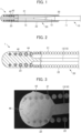
- FIG. 1 is a partial cross-sectional schematic view of a guide wire 1 according to an embodiment.
- FIG. 2 is an enlarged partial cross-sectional view of a vicinity of a distal end joint part of the guide wire 1.
- FIG. 1 illustrates only a part of a distal end side of the guide wire 1.
- the guide wire 1 includes a core shaft 10, a coil 20, a proximal end joint part 30 and a distal end joint part 40.
- the core shaft 10 includes a core shaft main body 11, a tapered portion 12, and a distal end portion 13.
- the tapered portion 12 extends continuously from the core shaft main body 11 while decreasing in diameter toward the distal end.
- the distal end portion 13 extends continuously from the tapered portion 12 toward the distal end.
- the core shaft main body 11 extends toward the rear end side, and a user performs a rotation operation or the like of the guide wire 1 at an end portion on the rear end side of the core shaft main body 11.
- Examples of the material constituting the core shaft 10 include stainless steels such as SUS302, SUS304, and SUS316.
- the coil 20 is provided to cover an outer periphery of the distal end of the core shaft main body 11, the tapered portion 12, and the distal end portion 13.
- the coil 20 is formed in a hollow cylindrical shape by spirally winding a strand 21 made up of, for example, tungsten around the core shaft 10.
- the coil 20 has a rear end portion 22 and a distal end portion 23.
- the strand 21 is wound to be in contact with each other in the axial direction.
- the strand 21 is wound to have a gap in the axial direction.
- the distal end portion 23 has an outer diameter smaller than that of the rear end portion 22.
- the distal end portion 23 is included in the distal end joint part 30.
- the material constituting the coil 20 is, for example, tungsten that is radiopaque. Tungsten constituting the coil 20 is used as a first material that is radiopaque.
- the stainless steel constituting the core shaft 10 is used as a second material different from the first material.
- a proximal end of the coil 20 is joined to the core shaft 10 by the proximal end joint part 30.
- the material constituting the proximal end joint part 30 include a brazing metal such as an Sn-Pb alloy, a Pb-Ag alloy, an Sn-Ag alloy, or an Au-Sn alloy, and an adhesive such as an epoxy-based resin.
- FIG. 3 is an image of a longitudinal cross-section of the distal end joint part 40.
- FIG. 4 is an element mapping image of a longitudinal cross-section of the distal end joint part 40.
- FIG. 5 is an explanatory view of a distal end portion 42 and a high concentration region 43 of the distal end joint part 40.
- FIG. 6 is an element mapping image of a longitudinal cross-section of the distal end joint part 40, which is an element mapping image with the enlarged strand 21.
- outer shapes of the distal end joint part 40 and the distal end portion 13 of the core shaft 10 are indicated by white dotted lines.
- FIGS. 4 to 6 are element mapping images of a longitudinal cross-section of the distal end joint part 40 acquired by using energy dispersive X-ray spectroscopy (EDX).
- EDX energy dispersive X-ray spectroscopy
- the distal end joint part 40 joins the distal end portion 13 of the core shaft 10 with the distal end portion 23 of the coil 20.
- the distal end joint part 40 encloses the distal end portion 23 of the coil 20.
- a diameter of the strand 21 of the distal end portion 23 decreases toward the distal end.
- the distal end of the distal end portion 23 is located near the distal end of the distal end joint part 40.
- the distal end joint part 40 is formed by melting a portion of the core shaft 10 originally located on the distal end side with respect to the distal end portion 13 and a part of the strand 21 of the distal end portion 23 by arc welding such as plasma welding.
- a black portion represents a material other than the first material such as stainless steel, and a gray or white portion represents the first material such as tungsten.
- the distal end joint part 40 includes a dispersion portion 42 in which the first material having radiopacity exists in a manner substantially uniformly dispersed in a certain range, and a high concentration region 43 in which a concentration of the first material is higher than that in the dispersion portion 42.
- a dispersion portion 42 in which the first material having radiopacity exists in a manner substantially uniformly dispersed in a certain range, and a high concentration region 43 in which a concentration of the first material is higher than that in the dispersion portion 42.
- a portion of a region surrounded by a dotted line except for the strands 21 is the dispersion portion 42, and a portion of a region surrounded by an alternate long and short dash line except for the strands 21 is the high concentration region 43.
- the high concentration region 43 exists on a rear end side of the distal end joint part 40.
- the dispersion portion 42 is a portion in which the first material (tungsten) having radiopacity exists in a manner substantially uniformly dispersed in a certain range.
- tungsten exists in a manner substantially uniformly dispersed in a certain range.
- the dispersion portion 42 is, for example, a portion where the molar ratio (%) of tungsten per unit area (1 ⁇ m 2 ) in the distal end joint part 40 is greater than 0% and less than 13.3%.
- the concentration of the first material in the dispersion portion 42 is relatively low compared to the high concentration region 43.
- the dispersion portion 42 exists to spread over the entire distal end side in the distal end joint part 40. As a result, the entire distal end side of the distal end joint part 40 can be visually recognized under radioscopy.
- the high concentration region 43 is a portion in which the concentration of the first material having radiopacity is relatively high compared to the dispersion portion 42.
- the high concentration region 43 is, for example, a portion where the molar ratio (%) of tungsten per unit area (1 ⁇ m 2 ) is 13.3% or more.
- the high concentration region 43 may be provided in any portion of the distal end joint part 40.
- the high concentration region 43 exists at the distal end of the distal end joint part 40, the visibility of the distal end of the distal end joint part 40 under radioscopy is improved.
- the high concentration region 43 exists at the rear end of the distal end joint part 40, visibility of a boundary portion between the distal end joint part 40 and the core shaft 10 under radioscopy is improved.
- a dendritic phase 44 made up of tungsten and extending outward in a dendritic shape from the strand 21 exists around the strand 21.
- the dendritic phase 44 exists to spread radially on the outer periphery of the strand 21.
- the strand 21 in the distal end joint part 40 has a convex portion on the outer periphery thereof.
- a part of the strand 21 made up of tungsten is melted by arc welding at the time of forming the distal end joint part 40, and the melted tungsten is distributed in the distal end joint part 40 as the dispersion portion 42 and the high concentration region 43 and around the strand 21 as the dendritic phase 44.
- the guide wire 1 is inserted into a blood vessel in a femoral region from the distal end joint part 40 and advanced to a coronary artery along the blood vessel.
- a treatment instrument such as a balloon catheter or a stent is conveyed along the guide wire 1, and various treatments are performed at the treated site.
- the guide wire 1 is made retrograde relative to the blood vessel and drawn out from a body, whereby a series of procedures is completed. A position of the distal end portion of the guide wire 1 in the blood vessel is confirmed by a radioscopic image.
- the above-described guide wire 1 includes the core shaft 10, the coil 20 made up of a strand that is spirally wound to cover the outer periphery of the core shaft 10, and the distal end joint part 40 that joins the distal end of the core shaft 10 and the distal end portion 23 of the coil 20.
- the distal end joint part 40 includes the dispersion portion 42 in which tungsten, which is radiopaque, is dispersed. This makes it possible to improve the visibility of the distal end joint part 40, which is the distal end portion of the guide wire 1, during X-ray irradiation.
- the distal end joint part 40 has the high concentration region 43 in which a concentration of tungsten is relatively high. This makes it possible to further improve the visibility of the distal end joint part 40, which is the distal end portion of the guide wire 1, during X-ray irradiation.
- the high concentration region 43 is located on the rear end side of the distal end joint part 40. As a result, it is possible to further improve the visibility of the rear end portion (the distal end of the distal end portion 13) of the distal end joint part 40, which is the distal end portion of the guide wire 1, during X-ray irradiation.
- the core shaft 10 is made up of stainless steel different from tungsten
- the coil 20 is made up of tungsten
- the distal end joint part 40 is formed by melting and joining the distal end portion 13 of the core shaft 10 and the distal end portion 23 of the coil 20.
- the distal end joint part 40 is integrally formed by melting the core shaft 10 and the coil 20, whereby a joint strength between the core shaft 10 and the coil 20 can be further improved.
- the joint strength between the core shaft 10 and the coil 20 can be further improved.
- the coil 20 is constituted by one strand 21, but may be constituted by a plurality of strands.
- the dispersion portion 42 is constituted of tungsten as a first material that is radiopaque and stainless steel as a second material through which X-rays are easily transmitted.
- other materials through which X-rays are easily transmitted and materials that is radiopaque may be used as long as it is possible to form a distal end joint part having a dispersion portion in which the first material having radiopacity exists in a manner substantially uniformly dispersed in a certain range of the second material through which X-rays are easily transmitted.
Landscapes
- Health & Medical Sciences (AREA)
- Life Sciences & Earth Sciences (AREA)
- Biophysics (AREA)
- Pulmonology (AREA)
- Engineering & Computer Science (AREA)
- Anesthesiology (AREA)
- Biomedical Technology (AREA)
- Heart & Thoracic Surgery (AREA)
- Hematology (AREA)
- Animal Behavior & Ethology (AREA)
- General Health & Medical Sciences (AREA)
- Public Health (AREA)
- Veterinary Medicine (AREA)
- Media Introduction/Drainage Providing Device (AREA)
Abstract
Description
- The present invention relates to a guide wire.
- When treating stenosis that occurs in blood vessels such as coronary arteries surrounding a heart, or when treating a site where a blood vessel is completely occluded (e.g., chronic total occlusion: CTO, etc.) due to a progression of calcification, a guide wire for guiding treatment instruments such as a balloon catheter is inserted into the blood vessel prior to the treatment instruments.
- In a guide wire of Patent Literature 1, a head is formed by melting only a distal end of a core wire made up of stainless steel. The core wire and a distal end of a wire coil are connected by the head.
- Patent Literature 1:
US Patent No. 4634042 - However, in a case of the guide wire of Patent Literature 1, since a distal end thereof is composed of only stainless steel, which is a material through which X-rays are easily transmitted, visibility of a distal end portion of the guide wire during X-ray irradiation is not so good.
- The present disclosure has been made based on the above circumstances, and an object of the present disclosure is to provide a guide wire that is capable of improving the visibility of the distal end portion thereof during X-ray irradiation.
- In order to solve the above-described problem, a guide wire according to an aspect of the disclosed embodiments includes: a core shaft; a coil made up of a strand that is spirally wound to cover an outer periphery of the core shaft; and a distal end joint part that joins a distal end of the core shaft and a distal end of the coil. The distal end joint part includes a dispersion portion in which a first material that is radiopaque is dispersed.
- The distal end joint part may include a high concentration region in which a concentration of the first material is relatively high.
- The high concentration region may be located on a rear end side of the distal end joint part.
- The core shaft may be made up of a second material different from the first material, the coil may be made up of the first material, and the distal end joint part may be formed by melting and joining a distal end portion of the core shaft and a distal end portion of the coil.
- The strand in the distal end joint part may have a convex portion.
- According to the disclosed embodiments, it is possible to provide a guide wire capable of improving visibility of a distal end portion thereof during X-ray irradiation.
-
-
FIG. 1 is a partial cross-sectional schematic view of a guide wire according to an embodiment. -
FIG. 2 is an enlarged partial cross-sectional view of a vicinity of a distal end joint part of the guide wire inFIG. 1 . -
FIG. 3 is an image of a longitudinal cross-section of the distal end joint part. -
FIG. 4 is an element mapping image of a longitudinal cross-section of the distal end joint part. -
FIG. 5 is an explanatory view of a distal end portion and a high concentration region of the distal end joint part. -
FIG. 6 is an element mapping image of a longitudinal cross-section of the distal end joint part, which is an element mapping image with strands enlarged. - Hereinafter, an embodiment of the present disclosure will be explained with reference to the drawings, but the disclosed embodiments are not limited only to the embodiments described in the drawings. Note that, in the present disclosure, a distal end means an end portion of the guide wire at which a distal end joint part is located, and a rear end means an end portion on a side opposite to the distal end.
-
FIG. 1 is a partial cross-sectional schematic view of a guide wire 1 according to an embodiment.FIG. 2 is an enlarged partial cross-sectional view of a vicinity of a distal end joint part of the guide wire 1.FIG. 1 illustrates only a part of a distal end side of the guide wire 1. - The guide wire 1 includes a
core shaft 10, acoil 20, a proximal endjoint part 30 and a distal endjoint part 40. - The
core shaft 10 includes a core shaftmain body 11, atapered portion 12, and adistal end portion 13. Thetapered portion 12 extends continuously from the core shaftmain body 11 while decreasing in diameter toward the distal end. Thedistal end portion 13 extends continuously from thetapered portion 12 toward the distal end. Although not described inFIG. 1 , the core shaftmain body 11 extends toward the rear end side, and a user performs a rotation operation or the like of the guide wire 1 at an end portion on the rear end side of the core shaftmain body 11. - Examples of the material constituting the
core shaft 10 include stainless steels such as SUS302, SUS304, and SUS316. - As illustrated in
FIG. 1 , thecoil 20 is provided to cover an outer periphery of the distal end of the core shaftmain body 11, thetapered portion 12, and thedistal end portion 13. Thecoil 20 is formed in a hollow cylindrical shape by spirally winding astrand 21 made up of, for example, tungsten around thecore shaft 10. - The
coil 20 has arear end portion 22 and adistal end portion 23. At therear end portion 22, thestrand 21 is wound to be in contact with each other in the axial direction. At thedistal end portion 23, thestrand 21 is wound to have a gap in the axial direction. Thedistal end portion 23 has an outer diameter smaller than that of therear end portion 22. Thedistal end portion 23 is included in the distal endjoint part 30. The material constituting thecoil 20 is, for example, tungsten that is radiopaque. Tungsten constituting thecoil 20 is used as a first material that is radiopaque. The stainless steel constituting thecore shaft 10 is used as a second material different from the first material. - A proximal end of the
coil 20 is joined to thecore shaft 10 by the proximal endjoint part 30. Examples of the material constituting the proximal endjoint part 30 include a brazing metal such as an Sn-Pb alloy, a Pb-Ag alloy, an Sn-Ag alloy, or an Au-Sn alloy, and an adhesive such as an epoxy-based resin. - Next, the distal end
joint part 40 will be explained.FIG. 3 is an image of a longitudinal cross-section of the distal endjoint part 40.FIG. 4 is an element mapping image of a longitudinal cross-section of the distal endjoint part 40.FIG. 5 is an explanatory view of adistal end portion 42 and ahigh concentration region 43 of the distal endjoint part 40.FIG. 6 is an element mapping image of a longitudinal cross-section of the distal endjoint part 40, which is an element mapping image with the enlargedstrand 21. InFIGS. 4 and 5 , outer shapes of the distal endjoint part 40 and thedistal end portion 13 of thecore shaft 10 are indicated by white dotted lines.FIGS. 4 to 6 are element mapping images of a longitudinal cross-section of the distal endjoint part 40 acquired by using energy dispersive X-ray spectroscopy (EDX). - The distal end
joint part 40 joins thedistal end portion 13 of thecore shaft 10 with thedistal end portion 23 of thecoil 20. The distal endjoint part 40 encloses thedistal end portion 23 of thecoil 20. A diameter of thestrand 21 of thedistal end portion 23 decreases toward the distal end. The distal end of thedistal end portion 23 is located near the distal end of the distal endjoint part 40. The distal endjoint part 40 is formed by melting a portion of thecore shaft 10 originally located on the distal end side with respect to thedistal end portion 13 and a part of thestrand 21 of thedistal end portion 23 by arc welding such as plasma welding. - As illustrated in
FIG. 4 , in the distal endjoint part 40, a black portion represents a material other than the first material such as stainless steel, and a gray or white portion represents the first material such as tungsten. The distal endjoint part 40 includes adispersion portion 42 in which the first material having radiopacity exists in a manner substantially uniformly dispersed in a certain range, and ahigh concentration region 43 in which a concentration of the first material is higher than that in thedispersion portion 42. In detail, in the distal endjoint part 40 ofFIG. 5 , a portion of a region surrounded by a dotted line except for thestrands 21 is thedispersion portion 42, and a portion of a region surrounded by an alternate long and short dash line except for thestrands 21 is thehigh concentration region 43. Thehigh concentration region 43 exists on a rear end side of the distal endjoint part 40. - The
dispersion portion 42 is a portion in which the first material (tungsten) having radiopacity exists in a manner substantially uniformly dispersed in a certain range. In thedispersion portion 42 of the present embodiment, tungsten exists in a manner substantially uniformly dispersed in a certain range. In the present embodiment, thedispersion portion 42 is, for example, a portion where the molar ratio (%) of tungsten per unit area (1µm2) in the distal endjoint part 40 is greater than 0% and less than 13.3%. The concentration of the first material in thedispersion portion 42 is relatively low compared to thehigh concentration region 43. In the present embodiment, thedispersion portion 42 exists to spread over the entire distal end side in the distal endjoint part 40. As a result, the entire distal end side of the distal endjoint part 40 can be visually recognized under radioscopy. - The
high concentration region 43 is a portion in which the concentration of the first material having radiopacity is relatively high compared to thedispersion portion 42. In the present embodiment, thehigh concentration region 43 is, for example, a portion where the molar ratio (%) of tungsten per unit area (1µm2) is 13.3% or more. Thehigh concentration region 43 may be provided in any portion of the distal endjoint part 40. When thehigh concentration region 43 exists at the distal end of the distal endjoint part 40, the visibility of the distal end of the distal endjoint part 40 under radioscopy is improved. When thehigh concentration region 43 exists at the rear end of the distal endjoint part 40, visibility of a boundary portion between the distal endjoint part 40 and thecore shaft 10 under radioscopy is improved. - As illustrated in
FIG. 6 , adendritic phase 44 made up of tungsten and extending outward in a dendritic shape from thestrand 21 exists around thestrand 21. Thedendritic phase 44 exists to spread radially on the outer periphery of thestrand 21. Namely, thestrand 21 in the distal endjoint part 40 has a convex portion on the outer periphery thereof. As described above, in the distal endjoint part 40, a part of thestrand 21 made up of tungsten is melted by arc welding at the time of forming the distal endjoint part 40, and the melted tungsten is distributed in the distal endjoint part 40 as thedispersion portion 42 and thehigh concentration region 43 and around thestrand 21 as thedendritic phase 44. - Next, a usage mode of the guide wire 1 will be explained. The guide wire 1 is inserted into a blood vessel in a femoral region from the distal end
joint part 40 and advanced to a coronary artery along the blood vessel. Next, after passing through a treated site such as a constricted part of a blood vessel or a false lumen in the vicinity of CTO, a treatment instrument such as a balloon catheter or a stent is conveyed along the guide wire 1, and various treatments are performed at the treated site. After the above-described treatments are completed, the guide wire 1 is made retrograde relative to the blood vessel and drawn out from a body, whereby a series of procedures is completed. A position of the distal end portion of the guide wire 1 in the blood vessel is confirmed by a radioscopic image. - The above-described guide wire 1 includes the
core shaft 10, thecoil 20 made up of a strand that is spirally wound to cover the outer periphery of thecore shaft 10, and the distal endjoint part 40 that joins the distal end of thecore shaft 10 and thedistal end portion 23 of thecoil 20. The distal endjoint part 40 includes thedispersion portion 42 in which tungsten, which is radiopaque, is dispersed. This makes it possible to improve the visibility of the distal endjoint part 40, which is the distal end portion of the guide wire 1, during X-ray irradiation. - The distal end
joint part 40 has thehigh concentration region 43 in which a concentration of tungsten is relatively high. This makes it possible to further improve the visibility of the distal endjoint part 40, which is the distal end portion of the guide wire 1, during X-ray irradiation. - The
high concentration region 43 is located on the rear end side of the distal endjoint part 40. As a result, it is possible to further improve the visibility of the rear end portion (the distal end of the distal end portion 13) of the distal endjoint part 40, which is the distal end portion of the guide wire 1, during X-ray irradiation. - The
core shaft 10 is made up of stainless steel different from tungsten, thecoil 20 is made up of tungsten, and the distal endjoint part 40 is formed by melting and joining thedistal end portion 13 of thecore shaft 10 and thedistal end portion 23 of thecoil 20. In this way, the distal endjoint part 40 is integrally formed by melting thecore shaft 10 and thecoil 20, whereby a joint strength between thecore shaft 10 and thecoil 20 can be further improved. - Since the
strand 21 in the distal endjoint part 40 has a convex portion, the joint strength between thecore shaft 10 and thecoil 20 can be further improved. - Note that the disclosed embodiments are not limited to the configuration of the above-mentioned embodiment, but is defined by the scope of claims, and is intended to include all modifications within the meaning and scope of equivalents to the scope of claims.
- For example, in the above-described embodiment, the
coil 20 is constituted by onestrand 21, but may be constituted by a plurality of strands. Thedispersion portion 42 is constituted of tungsten as a first material that is radiopaque and stainless steel as a second material through which X-rays are easily transmitted. However, other materials through which X-rays are easily transmitted and materials that is radiopaque may be used as long as it is possible to form a distal end joint part having a dispersion portion in which the first material having radiopacity exists in a manner substantially uniformly dispersed in a certain range of the second material through which X-rays are easily transmitted. -
- 1
- Guide wire
- 10
- Core shaft
- 20
- Coil
- 23
- Distal end portion
- 40
- Distal end j oint part
- 42
- Dispersion portion
- 43
- High concentration region
- 44
- Dendritic phase
Claims (5)
- A guide wire comprising:a core shaft;a coil made up of a strand that is spirally wound to cover an outer periphery of the core shaft; anda distal end joint part that joins a distal end of the core shaft and a distal end of the coil, whereinthe distal end joint part has a dispersion portion in which a first material that is radiopaque is dispersed.
- The guide wire according to claim 1, wherein the distal end joint part includes a high concentration region in which a concentration of the first material is relatively high.
- The guide wire according to claim 2, wherein the high concentration region is located on a rear end side of the distal end joint part.
- The guide wire according to any one of claims 1 to 3, whereinthe core shaft is made up of a second material different from the first material,the coil is made up of the first material, andthe distal end joint part is formed by melting and joining a distal end portion of the core shaft and a distal end portion of the coil.
- The guide wire according to any one of claims 1 to 4, wherein the strand in the distal end joint part has a convex portion.
Applications Claiming Priority (2)
| Application Number | Priority Date | Filing Date | Title |
|---|---|---|---|
| JP2021192234A JP7749426B2 (en) | 2021-11-26 | 2021-11-26 | Guidewire |
| PCT/JP2022/038325 WO2023095481A1 (en) | 2021-11-26 | 2022-10-14 | Guide wire |
Publications (3)
| Publication Number | Publication Date |
|---|---|
| EP4438099A1 true EP4438099A1 (en) | 2024-10-02 |
| EP4438099A4 EP4438099A4 (en) | 2025-11-12 |
| EP4438099B1 EP4438099B1 (en) | 2026-04-08 |
Family
ID=86539216
Family Applications (1)
| Application Number | Title | Priority Date | Filing Date |
|---|---|---|---|
| EP22898265.8A Active EP4438099B1 (en) | 2021-11-26 | 2022-10-14 | Guide wire |
Country Status (5)
| Country | Link |
|---|---|
| US (1) | US20240299711A1 (en) |
| EP (1) | EP4438099B1 (en) |
| JP (1) | JP7749426B2 (en) |
| CN (1) | CN118302221A (en) |
| WO (1) | WO2023095481A1 (en) |
Family Cites Families (6)
| Publication number | Priority date | Publication date | Assignee | Title |
|---|---|---|---|---|
| US4634042A (en) | 1984-04-10 | 1987-01-06 | Cordis Corporation | Method of joining refractory metals to lower melting dissimilar metals |
| WO1991000051A1 (en) * | 1989-06-28 | 1991-01-10 | Boston Scientific Corporation | Steerable highly elongated guidewire |
| US5488959A (en) * | 1993-12-27 | 1996-02-06 | Cordis Corporation | Medical guidewire and welding process |
| JP4308801B2 (en) * | 2005-08-12 | 2009-08-05 | 株式会社エフエムディ | Medical guide wire and manufacturing method thereof |
| JP2014161705A (en) * | 2013-02-28 | 2014-09-08 | Asahi Intecc Co Ltd | Guide wire |
| US20220175256A1 (en) * | 2019-04-25 | 2022-06-09 | Opsens, Inc. | Guidewire with internal pressure sensor |
-
2021
- 2021-11-26 JP JP2021192234A patent/JP7749426B2/en active Active
-
2022
- 2022-10-14 WO PCT/JP2022/038325 patent/WO2023095481A1/en not_active Ceased
- 2022-10-14 EP EP22898265.8A patent/EP4438099B1/en active Active
- 2022-10-14 CN CN202280077769.6A patent/CN118302221A/en active Pending
-
2024
- 2024-05-15 US US18/665,247 patent/US20240299711A1/en active Pending
Also Published As
| Publication number | Publication date |
|---|---|
| EP4438099B1 (en) | 2026-04-08 |
| JP2023078906A (en) | 2023-06-07 |
| JP7749426B2 (en) | 2025-10-06 |
| CN118302221A (en) | 2024-07-05 |
| EP4438099A4 (en) | 2025-11-12 |
| WO2023095481A1 (en) | 2023-06-01 |
| US20240299711A1 (en) | 2024-09-12 |
Similar Documents
| Publication | Publication Date | Title |
|---|---|---|
| US11701497B2 (en) | Guide wire | |
| JP2012152478A (en) | Guidewire | |
| EP2921197B1 (en) | Guidewire | |
| EP3695873B1 (en) | Guide wire | |
| US11484687B2 (en) | Catheter | |
| US20230121231A1 (en) | Guide Wires | |
| US11420028B2 (en) | Guide wire | |
| JP6724251B2 (en) | Guide wire for plasma | |
| EP4438099B1 (en) | Guide wire | |
| US12151069B2 (en) | Guide wire | |
| US20200353216A1 (en) | Catheter | |
| US20230181879A1 (en) | Guide wire | |
| US20220105310A1 (en) | Hollow shaft and catheter | |
| US20220096802A1 (en) | Guide wire | |
| EP3006075B1 (en) | Guidewire | |
| EP4360688A1 (en) | Guide wire | |
| JP2019097777A (en) | Guide wire |
Legal Events
| Date | Code | Title | Description |
|---|---|---|---|
| STAA | Information on the status of an ep patent application or granted ep patent |
Free format text: STATUS: THE INTERNATIONAL PUBLICATION HAS BEEN MADE |
|
| PUAI | Public reference made under article 153(3) epc to a published international application that has entered the european phase |
Free format text: ORIGINAL CODE: 0009012 |
|
| STAA | Information on the status of an ep patent application or granted ep patent |
Free format text: STATUS: REQUEST FOR EXAMINATION WAS MADE |
|
| 17P | Request for examination filed |
Effective date: 20240531 |
|
| AK | Designated contracting states |
Kind code of ref document: A1 Designated state(s): AL AT BE BG CH CY CZ DE DK EE ES FI FR GB GR HR HU IE IS IT LI LT LU LV MC ME MK MT NL NO PL PT RO RS SE SI SK SM TR |
|
| DAV | Request for validation of the european patent (deleted) | ||
| DAX | Request for extension of the european patent (deleted) | ||
| A4 | Supplementary search report drawn up and despatched |
Effective date: 20251015 |
|
| RIC1 | Information provided on ipc code assigned before grant |
Ipc: A61M 25/09 20060101AFI20251009BHEP Ipc: A61M 25/098 20060101ALI20251009BHEP Ipc: A61M 25/01 20060101ALI20251009BHEP |
|
| GRAP | Despatch of communication of intention to grant a patent |
Free format text: ORIGINAL CODE: EPIDOSNIGR1 |
|
| STAA | Information on the status of an ep patent application or granted ep patent |
Free format text: STATUS: GRANT OF PATENT IS INTENDED |
|
| INTG | Intention to grant announced |
Effective date: 20251212 |
|
| GRAS | Grant fee paid |
Free format text: ORIGINAL CODE: EPIDOSNIGR3 |
|
| GRAA | (expected) grant |
Free format text: ORIGINAL CODE: 0009210 |
|
| STAA | Information on the status of an ep patent application or granted ep patent |
Free format text: STATUS: THE PATENT HAS BEEN GRANTED |
|
| GRAT | Correction requested after decision to grant or after decision to maintain patent in amended form |
Free format text: ORIGINAL CODE: EPIDOSNCDEC |
|
| AK | Designated contracting states |
Kind code of ref document: B1 Designated state(s): AL AT BE BG CH CY CZ DE DK EE ES FI FR GB GR HR HU IE IS IT LI LT LU LV MC ME MK MT NL NO PL PT RO RS SE SI SK SM TR |
|
| REG | Reference to a national code |
Ref country code: CH Ref legal event code: F10 Free format text: ST27 STATUS EVENT CODE: U-0-0-F10-F00 (AS PROVIDED BY THE NATIONAL OFFICE) Effective date: 20260408 Ref country code: GB Ref legal event code: FG4D |
|
| RAP4 | Party data changed (patent owner data changed or rights of a patent transferred) |
Owner name: ASAHI INTECC CO., LTD. |
|
| REG | Reference to a national code |
Ref country code: CH Ref legal event code: Q17 Free format text: ST27 STATUS EVENT CODE: U-0-0-Q10-Q17 (AS PROVIDED BY THE NATIONAL OFFICE) Effective date: 20260430 Ref country code: DE Ref legal event code: R096 Ref document number: 602022034338 Country of ref document: DE |