WO2023095481A1 - Guide wire - Google Patents
Guide wire Download PDFInfo
- Publication number
- WO2023095481A1 WO2023095481A1 PCT/JP2022/038325 JP2022038325W WO2023095481A1 WO 2023095481 A1 WO2023095481 A1 WO 2023095481A1 JP 2022038325 W JP2022038325 W JP 2022038325W WO 2023095481 A1 WO2023095481 A1 WO 2023095481A1
- Authority
- WO
- WIPO (PCT)
- Prior art keywords
- tip
- core shaft
- coil
- guide wire
- wire
- Prior art date
Links
Images

Classifications
-
- A—HUMAN NECESSITIES
- A61—MEDICAL OR VETERINARY SCIENCE; HYGIENE
- A61M—DEVICES FOR INTRODUCING MEDIA INTO, OR ONTO, THE BODY; DEVICES FOR TRANSDUCING BODY MEDIA OR FOR TAKING MEDIA FROM THE BODY; DEVICES FOR PRODUCING OR ENDING SLEEP OR STUPOR
- A61M25/00—Catheters; Hollow probes
- A61M25/01—Introducing, guiding, advancing, emplacing or holding catheters
- A61M25/0105—Steering means as part of the catheter or advancing means; Markers for positioning
- A61M25/0108—Steering means as part of the catheter or advancing means; Markers for positioning using radio-opaque or ultrasound markers
-
- A—HUMAN NECESSITIES
- A61—MEDICAL OR VETERINARY SCIENCE; HYGIENE
- A61M—DEVICES FOR INTRODUCING MEDIA INTO, OR ONTO, THE BODY; DEVICES FOR TRANSDUCING BODY MEDIA OR FOR TAKING MEDIA FROM THE BODY; DEVICES FOR PRODUCING OR ENDING SLEEP OR STUPOR
- A61M25/00—Catheters; Hollow probes
- A61M25/01—Introducing, guiding, advancing, emplacing or holding catheters
- A61M25/09—Guide wires
Definitions
- the present invention relates to guidewires.
- therapeutic instruments such as balloon catheters.
- a guide wire is inserted into the blood vessel to guide them in advance.
- the present disclosure has been made based on the circumstances as described above, and its purpose is to provide a guide wire capable of improving the visibility of the distal end during X-ray irradiation.
- a guidewire includes a core shaft, a coil made of a wire spirally wound so as to cover the outer circumference of the core shaft, and a tip end of the core shaft. and a tip joint joining the tip of the coil, the tip joint having a dispersion in which a radiopaque first material is dispersed.
- the tip junction may have a high-concentration region in which the concentration of the first material is relatively high.
- the high-concentration region may be located on the rear end side of the tip junction.
- the core shaft is made of a second material that is different from the first material
- the coil is made of the first material
- the tip joint portion includes a tip portion of the core shaft and a tip portion of the coil. It may be formed by melting and bonding.
- the wire in the tip joint portion may have a convex portion.
- the present invention can provide a guide wire that can improve the visibility of the distal end during X-ray irradiation.
- FIG. 1 is a schematic partial cross-sectional view of a guidewire according to an embodiment
- FIG. FIG. 2 is an enlarged partial cross-sectional view of the vicinity of the tip joint portion of the guide wire in FIG. 1
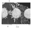
- Fig. 3 is an image of a longitudinal section of the tip joint
- It is an elemental mapping image of the longitudinal section of the tip joint.
- FIG. 4 is an explanatory diagram of the tip of the tip junction and the high-concentration region; It is an elemental mapping image of the vertical cross section of the tip joint, and is an elemental mapping image in which the wire is enlarged.
- the distal end means the end of the guidewire where the distal junction is located, and the posterior end means the end opposite to the distal end.
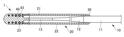
- FIG. 1 is a schematic partial cross-sectional view of a guidewire 1 according to an embodiment.
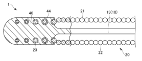
- FIG. 2 is an enlarged partial cross-sectional view of the vicinity of the tip junction of the guide wire 1.
- FIG. FIG. 1 shows only a part of the guide wire 1 on the distal side.
- the guidewire 1 comprises a core shaft 10 , a coil 20 , a proximal junction 30 and a distal junction 40 .
- the core shaft 10 has a core shaft main body 11 , a tapered portion 12 and a tip portion 13 .
- the tapered portion 12 extends continuously from the core shaft body 11 toward the distal end while decreasing in diameter.
- the tip portion 13 extends continuously from the tapered portion 12 toward the tip.
- the core shaft body 11 extends toward the rear end side, and the user can rotate the guide wire 1 at the rear end side of the core shaft body 11 . done.
- Examples of materials forming the core shaft 10 include stainless steel such as SUS302, SUS304, and SUS316.
- the coil 20 is provided so as to cover the tip of the core shaft body 11, the tapered portion 12, and the outer periphery of the tip portion 13.
- the coil 20 is formed in a hollow cylindrical shape by spirally winding a wire 21 made of, for example, tungsten around the core shaft 10 .
- the coil 20 has a rear end portion 22 and a front end portion 23 .
- the rear end portion 22 is wound so that the wire 21 abuts thereon in the axial direction.
- the tip portion 23 is wound so that the wire 21 has a gap in the axial direction.
- the front end portion 23 is configured to have a smaller outer diameter than the rear end portion 22 .
- the tip portion 23 is included in the tip joint portion 30 .
- Examples of the material forming the coil 20 include X-ray opaque tungsten. Tungsten, which constitutes the coil 20, is the radiopaque first material.
- the stainless steel forming the core shaft 10 is a second material different from the first material.
- a proximal end of the coil 20 is joined to the core shaft 10 by a proximal joint portion 30 .
- the material forming the base end joint portion 30 include solder metal such as Sn--Pb alloy, Pb--Ag alloy, Sn--Ag alloy and Au--Sn alloy, and adhesive such as epoxy resin.
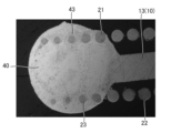
- FIG. 3 is a longitudinal cross-sectional image of the tip joint 40 .
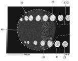
- FIG. 4 is an elemental mapping image of a longitudinal section of the tip joint 40.
- FIG. 5 is an explanatory diagram of the tip portion 42 and the high-concentration region 43 of the tip junction portion 40 .
- FIG. 6 is an elemental mapping image of a longitudinal section of the tip joint portion 40, which is an enlarged elemental mapping image of the wire 21.
- the outlines of the tip joint portion 40 and the tip portion 13 of the core shaft 10 are indicated by white dotted lines.
- 4 to 6 are elemental mapping images of longitudinal cross sections of the tip joint 40 obtained using EDX (Energy Dispersive X-ray Spectroscopy).
- the tip joint 40 joins the tip of the tip 13 of the core shaft 10 and the tip 23 of the coil 20 .
- the tip joint portion 40 includes the tip portion 23 of the coil 20 .
- the diameter of the wire 21 at the tip portion 23 decreases toward the tip.
- the tip of the tip portion 23 is located near the tip of the tip joint portion 40 .
- the tip joint portion 40 is formed by melting a portion of the core shaft 10 that was originally located on the tip side of the tip portion 13 and a part of the wire 21 of the tip portion 23 by arc welding such as plasma welding. It is
- the black portion of the tip joint portion 40 is a material other than the first material such as stainless steel, and the gray or white portion is the first material such as tungsten.
- the tip joint portion 40 includes a dispersed portion 42 which is a portion in which a first material having radiopacity is dispersed substantially uniformly within a certain range, and a high concentration of the first material higher than that of the dispersed portion 42 . It has a region 43 .
- the portion excluding the wire 21 in the area surrounded by the dotted line is the dispersed portion 42
- the portion excluding the wire 21 in the area surrounded by the dashed line is This is the high-concentration region 43 .
- the high-concentration region 43 exists on the rear end side of the tip junction portion 40 .
- the dispersed portion 42 is a portion in which the radiopaque first material (tungsten) is dispersed substantially uniformly within a certain range.
- tungsten is distributed substantially uniformly within a certain range.
- the dispersed portion 42 is, for example, a portion in which the molar ratio (%) of tungsten per unit area (1 ⁇ m 2 ) in the tip joint portion 40 is greater than 0% and less than 13.3%.
- the concentration of the first material in the dispersed portion 42 is relatively low compared to the high concentration region 43 .
- the distributed portion 42 exists so as to spread over the entire distal end side in the distal joint portion 40 . As a result, the entire distal end side of the distal joint portion 40 can be visually recognized under X-ray fluoroscopy.
- the high-concentration region 43 is a portion where the concentration of the radiopaque first material is relatively high compared to the dispersed portion 42 .
- the high-concentration region 43 is, for example, a portion where the molar ratio (%) of tungsten per unit area (1 ⁇ m 2 ) is 13.3% or more. Dense region 43 may be at any portion of tip junction 40 .
- the high-concentration region 43 exists at the tip of the tip joint portion 40, the visibility of the tip of the tip joint portion 40 under X-ray fluoroscopy is improved.
- the high concentration region 43 exists at the rear end of the tip joint portion 40, the visibility of the boundary portion between the tip joint portion 40 and the core shaft 10 under X-ray fluoroscopy is improved.
- a dendritic phase 44 made of tungsten and extending outward from the wire 21 in a dendritic manner exists around the wire 21 .
- the dendritic phase 44 exists so as to spread radially on the outer circumference of the wire 21 . That is, the wire 21 in the tip joint portion 40 has a convex portion on its outer circumference.
- part of the wire 21 made of tungsten is melted by arc welding during its formation, and the molten tungsten forms the dispersed portion 42 and the high-concentration region 43 in the tip joint 40, and , distributed around the wire 21 as a dendritic phase 44 .
- the guide wire 1 is inserted into the femoral blood vessel from the distal joint 40 and advanced along the blood vessel to the coronary artery.
- a therapeutic instrument such as a balloon catheter or a stent is transported along the guidewire 1, and various treatments are performed at the treatment site. do.
- the guidewire 1 is withdrawn from the body retrograde the blood vessel, completing the series of operations. The position of the distal end of the guide wire 1 inside the blood vessel is confirmed with an X-ray fluoroscopic image.
- the core shaft 10 the coil 20 made of a wire spirally wound so as to cover the outer circumference of the core shaft 10, the tip of the core shaft 10 and the tip 23 of the coil 20 a tip joint 40 that joins the tip joint 40 having a dispersion 42 in which radiopaque tungsten is dispersed.
- the visibility of the distal joint portion 40 which is the distal end portion of the guide wire 1, during X-ray irradiation can be improved.
- the tip junction 40 has a high-concentration region 43 in which the concentration of tungsten is relatively high. As a result, the visibility of the distal joint portion 40, which is the distal end portion of the guide wire 1, during X-ray irradiation can be further improved.
- the high-concentration region 43 is located on the rear end side of the tip joint portion 40 .
- the visibility of the rear end of the distal joint portion 40 (the distal end of the distal end portion 13), which is the distal end portion of the guide wire 1 during X-ray irradiation, can be further improved.
- the core shaft 10 is made of stainless steel different from tungsten
- the coil 20 is made of tungsten
- the tip joint portion 40 melts and joins the tip portion 13 of the core shaft 10 and the tip portion 23 of the coil 20. It is formed by Thus, by melting the core shaft 10 and the coil 20 to integrally form the tip joint portion 40, the joint strength between the core shaft 10 and the coil 20 can be further improved.
- the joint strength between the core shaft 10 and the coil 20 can be further improved.
- the coil 20 is composed of one wire 21, but may be composed of a plurality of wires.
- the dispersion section 42 was constructed of tungsten as the first radiopaque material and stainless steel as the second radiopaque material.
- the first material having X-ray opacity is a material capable of forming a tip joint portion having dispersed portions that are substantially uniformly dispersed within a certain range of the second material that easily transmits X-rays. , other X-ray transparent materials and radiopaque materials.
Abstract
The purpose of the present invention is to provide a guide wire with which it is possible to improve visibility of a leading end thereof when irradiated with X-rays. The guide wire comprises: a core shaft; a coil made up of a strand that is helically wound so as to cover the outer circumference of the core shaft; and a leading end joining part that joins the leading end of the coil and the leading end of the core shaft. The leading end joining part has a dispersion portion in which a radiopaque first material is dispersed.
Description
本発明は、ガイドワイヤに関する。
The present invention relates to guidewires.
心臓を取り巻く冠動脈などの血管に生じた狭窄の治療や、石灰化の進行により血管内が完全に閉塞した部位(例えば、慢性完全閉塞:CTOなど)を治療する際、バルーンカテーテル等の治療器具に先行してこれらを案内するためのガイドワイヤが血管に挿入される。
For treatment of stenosis in blood vessels such as the coronary arteries surrounding the heart, and treatment of areas where the blood vessels are completely occluded due to progress of calcification (e.g., chronic total occlusion: CTO), therapeutic instruments such as balloon catheters. A guide wire is inserted into the blood vessel to guide them in advance.
特許文献1のガイドワイヤでは、ステンレス鋼からなるコアワイヤの遠位端のみを溶融してヘッドを形成し、ヘッドによりコアワイヤとワイヤコイルの遠位端とを接続している。
In the guide wire of Patent Document 1, only the distal end of the core wire made of stainless steel is melted to form a head, and the head connects the core wire and the distal end of the wire coil.
しかしながら、特許文献1のガイドワイヤの場合、その先端はX線を透過しやすい材料であるステンレス鋼のみから構成されているため、X線照射時のガイドワイヤの先端部の視認性があまり良くない。
However, in the case of the guide wire of Patent Document 1, since the tip is made only of stainless steel, which is a material that easily transmits X-rays, the visibility of the tip of the guide wire during X-ray irradiation is not very good. .
本開示は、以上のような事情に基づいてなされたものであり、その目的は、X線照射時の先端部の視認性を向上させることができるガイドワイヤを提供することにある。
The present disclosure has been made based on the circumstances as described above, and its purpose is to provide a guide wire capable of improving the visibility of the distal end during X-ray irradiation.
上記課題を解決するために、本発明の一形態に係るガイドワイヤは、コアシャフトと、前記コアシャフトの外周を覆うように螺旋状に巻かれた素線からなるコイルと、前記コアシャフトの先端と前記コイルの先端とを接合する先端接合部と、を備え、前記先端接合部は、X線不透過性の第1材料が分散する分散部を有する。
In order to solve the above problems, a guidewire according to one aspect of the present invention includes a core shaft, a coil made of a wire spirally wound so as to cover the outer circumference of the core shaft, and a tip end of the core shaft. and a tip joint joining the tip of the coil, the tip joint having a dispersion in which a radiopaque first material is dispersed.
前記先端接合部は、前記第1材料の濃度が相対的に高い高濃度領域を有してもよい。
The tip junction may have a high-concentration region in which the concentration of the first material is relatively high.
前記高濃度領域は、前記先端接合部の後端側に位置していてもよい。
The high-concentration region may be located on the rear end side of the tip junction.
前記コアシャフトは、前記第1材料と異なる第2材料からなり、前記コイルは、前記第1材料からなり、前記先端接合部は、前記コアシャフトの先端部と、前記コイルの先端部と、を溶融して接合することにより形成されてもよい。
The core shaft is made of a second material that is different from the first material, the coil is made of the first material, and the tip joint portion includes a tip portion of the core shaft and a tip portion of the coil. It may be formed by melting and bonding.
前記先端接合部内の前記素線は凸部を有してもよい。
The wire in the tip joint portion may have a convex portion.
本発明は、X線照射時の先端部の視認性を向上させることができるガイドワイヤを提供することができる。
The present invention can provide a guide wire that can improve the visibility of the distal end during X-ray irradiation.
以下、本開示の一実施形態について図面を参照して説明するが、本発明は、当該図面に記載の実施形態にのみ限定されるものではない。なお、本開示において、先端とはガイドワイヤにおいて先端接合部が位置する端部を意味し、後端とは当該先端とは反対側の端部を意味する。
An embodiment of the present disclosure will be described below with reference to the drawings, but the present invention is not limited only to the embodiments described in the drawings. In the present disclosure, the distal end means the end of the guidewire where the distal junction is located, and the posterior end means the end opposite to the distal end.
図1は、実施形態に係るガイドワイヤ1の一部断面概略図である。図2は、ガイドワイヤ1の先端接合部付近の拡大一部断面図である。図1は、ガイドワイヤ1の先端側の一部のみを図示している。
ガイドワイヤ1は、コアシャフト10と、コイル20と、基端接合部30と、先端接合部40とを備える。 FIG. 1 is a schematic partial cross-sectional view of aguidewire 1 according to an embodiment. FIG. 2 is an enlarged partial cross-sectional view of the vicinity of the tip junction of the guide wire 1. FIG. FIG. 1 shows only a part of the guide wire 1 on the distal side.
Theguidewire 1 comprises a core shaft 10 , a coil 20 , a proximal junction 30 and a distal junction 40 .
ガイドワイヤ1は、コアシャフト10と、コイル20と、基端接合部30と、先端接合部40とを備える。 FIG. 1 is a schematic partial cross-sectional view of a
The
コアシャフト10は、コアシャフト本体11と、テーパ部12と、先端部13とを有する。テーパ部12は、コアシャフト本体11から連続して先端に向かって縮径しながら延びている。先端部13は、テーパ部12から連続して先端に向かって延びている。なお、図1には記載されていないが、コアシャフト本体11は、後端側に向かって延びており、コアシャフト本体11の後端側の端部においてユーザによるガイドワイヤ1の回転操作等が行われる。
The core shaft 10 has a core shaft main body 11 , a tapered portion 12 and a tip portion 13 . The tapered portion 12 extends continuously from the core shaft body 11 toward the distal end while decreasing in diameter. The tip portion 13 extends continuously from the tapered portion 12 toward the tip. Although not shown in FIG. 1 , the core shaft body 11 extends toward the rear end side, and the user can rotate the guide wire 1 at the rear end side of the core shaft body 11 . done.
コアシャフト10を構成する材料としては、例えば、SUS302、SUS304、SUS316などのステンレス鋼が挙げられる。
Examples of materials forming the core shaft 10 include stainless steel such as SUS302, SUS304, and SUS316.
図1に示すように、コイル20は、コアシャフト本体11の先端、テーパ部12、および先端部13の外周を覆うように設けられている。コイル20は、例えばタングステンからなる一本の素線21をコアシャフト10の周りに螺旋状に巻回することにより、中空円筒形状に形成されている。
As shown in FIG. 1, the coil 20 is provided so as to cover the tip of the core shaft body 11, the tapered portion 12, and the outer periphery of the tip portion 13. The coil 20 is formed in a hollow cylindrical shape by spirally winding a wire 21 made of, for example, tungsten around the core shaft 10 .
コイル20は、後端部22と、先端部23とを有する。後端部22は、素線21が軸方向において当接するように巻回されている。先端部23は、素線21が軸方向において隙間を有するように巻回されている。先端部23は、後端部22よりも外径が小さく構成されている。先端部23は、先端接合部30に内包されている。コイル20を構成する材料としては、例えば、X線不透過性のタングステンが挙げられる。コイル20を構成するタングステンをX線不透過性の第1材料とする。コアシャフト10を構成するステンレス鋼を第1材料とは異なる第2材料とする。
The coil 20 has a rear end portion 22 and a front end portion 23 . The rear end portion 22 is wound so that the wire 21 abuts thereon in the axial direction. The tip portion 23 is wound so that the wire 21 has a gap in the axial direction. The front end portion 23 is configured to have a smaller outer diameter than the rear end portion 22 . The tip portion 23 is included in the tip joint portion 30 . Examples of the material forming the coil 20 include X-ray opaque tungsten. Tungsten, which constitutes the coil 20, is the radiopaque first material. The stainless steel forming the core shaft 10 is a second material different from the first material.
コイル20の基端は、基端接合部30によりコアシャフト10に接合されている。基端接合部30を構成する材料としては、例えば、Sn-Pb合金、Pb-Ag合金、Sn-Ag合金、Au-Sn合金等の金属ロウや、エポキシ系樹脂などの接着剤が挙げられる。
A proximal end of the coil 20 is joined to the core shaft 10 by a proximal joint portion 30 . Examples of the material forming the base end joint portion 30 include solder metal such as Sn--Pb alloy, Pb--Ag alloy, Sn--Ag alloy and Au--Sn alloy, and adhesive such as epoxy resin.
次に、先端接合部40について説明する。図3は、先端接合部40の縦断面の画像である。図4は、先端接合部40の縦断面の元素マッピング像である。図5は、先端接合部40の先端部42および高濃度領域43の説明図である。図6は、先端接合部40の縦断面の元素マッピング像であって、素線21を拡大した元素マッピング像である。図4、5では、先端接合部40およびコアシャフト10の先端部13の外形を白の点線で示している。図4~6は、EDX(エネルギー分散型X線分光法)を用いて得られた先端接合部40の縦断面の元素マッピング像である。
Next, the tip joint portion 40 will be described. FIG. 3 is a longitudinal cross-sectional image of the tip joint 40 . FIG. 4 is an elemental mapping image of a longitudinal section of the tip joint 40. As shown in FIG. FIG. 5 is an explanatory diagram of the tip portion 42 and the high-concentration region 43 of the tip junction portion 40 . FIG. 6 is an elemental mapping image of a longitudinal section of the tip joint portion 40, which is an enlarged elemental mapping image of the wire 21. As shown in FIG. In FIGS. 4 and 5, the outlines of the tip joint portion 40 and the tip portion 13 of the core shaft 10 are indicated by white dotted lines. 4 to 6 are elemental mapping images of longitudinal cross sections of the tip joint 40 obtained using EDX (Energy Dispersive X-ray Spectroscopy).
先端接合部40は、コアシャフト10の先端部13の先端と、コイル20の先端部23とを接合している。先端接合部40は、コイル20の先端部23を内包している。先端部23の素線21の直径は、先端に行くほど小さくなっている。先端部23の先端は、先端接合部40の先端付近に位置している。先端接合部40は、元々コアシャフト10の先端部13よりも先端側に位置していた部分と、先端部23の素線21の一部とをプラズマ溶接等のアーク溶接により溶融させることにより形成されている。
The tip joint 40 joins the tip of the tip 13 of the core shaft 10 and the tip 23 of the coil 20 . The tip joint portion 40 includes the tip portion 23 of the coil 20 . The diameter of the wire 21 at the tip portion 23 decreases toward the tip. The tip of the tip portion 23 is located near the tip of the tip joint portion 40 . The tip joint portion 40 is formed by melting a portion of the core shaft 10 that was originally located on the tip side of the tip portion 13 and a part of the wire 21 of the tip portion 23 by arc welding such as plasma welding. It is
図4に示すように、先端接合部40のうち、黒色の部分はステンレス鋼などの第1材料以外の材料であり、灰色または白色の部分はタングステンなどの第1材料である。先端接合部40は、X線不透過性を有する第1材料が一定範囲中に略均一に分散して存在する部分である分散部42と、第1材料の濃度が分散部42より大きい高濃度領域43を有する。詳細には、図5の先端接合部40において、点線で囲んだ領域のうち、素線21を除く部分が分散部42であり、一点鎖線で囲んだ領域のうち、素線21を除く部分が高濃度領域43である。高濃度領域43は、先端接合部40の後端側に存在している。
As shown in FIG. 4, the black portion of the tip joint portion 40 is a material other than the first material such as stainless steel, and the gray or white portion is the first material such as tungsten. The tip joint portion 40 includes a dispersed portion 42 which is a portion in which a first material having radiopacity is dispersed substantially uniformly within a certain range, and a high concentration of the first material higher than that of the dispersed portion 42 . It has a region 43 . Specifically, in the tip joint portion 40 in FIG. 5 , the portion excluding the wire 21 in the area surrounded by the dotted line is the dispersed portion 42 , and the portion excluding the wire 21 in the area surrounded by the dashed line is This is the high-concentration region 43 . The high-concentration region 43 exists on the rear end side of the tip junction portion 40 .
分散部42とは、X線不透過性を有する第1材料(タングステン)が一定範囲中に略均一に分散して存在する部分である。本実施形態の分散部42においては、タングステンが一定範囲中に略均一に分散して存在する。本実施形態においては、分散部42は、例えば、先端接合部40における単位面積(1μm2)当たりのタングステンのモル比(%)が0%より大きく、13.3%より小さい部分とする。分散部42における第1材料の濃度は、高濃度領域43と比較して相対的に低い。本実施形態において分散部42は、先端接合部40内の先端側全体に広がるように存在している。これにより、先端接合部40の先端側全体がX線透視下で視認可能となる。
The dispersed portion 42 is a portion in which the radiopaque first material (tungsten) is dispersed substantially uniformly within a certain range. In the dispersed portion 42 of the present embodiment, tungsten is distributed substantially uniformly within a certain range. In the present embodiment, the dispersed portion 42 is, for example, a portion in which the molar ratio (%) of tungsten per unit area (1 μm 2 ) in the tip joint portion 40 is greater than 0% and less than 13.3%. The concentration of the first material in the dispersed portion 42 is relatively low compared to the high concentration region 43 . In the present embodiment, the distributed portion 42 exists so as to spread over the entire distal end side in the distal joint portion 40 . As a result, the entire distal end side of the distal joint portion 40 can be visually recognized under X-ray fluoroscopy.
高濃度領域43とは、X線不透過性を有する第1材料の濃度が、分散部42と比較して相対的に高い部分である。本実施形態においては、高濃度領域43は、例えば、単位面積(1μm2)当たりのタングステンのモル比(%)が13.3%以上の部分とする。高濃度領域43は先端接合部40のうちのどの部分にあってもよい。先端接合部40の先端に高濃度領域43が存在する場合は、X線透視下における先端接合部40の先端の視認性が向上する。先端接合部40の後端に高濃度領域43が存在する場合は、X線透視下における先端接合部40とコアシャフト10との境界部の視認性が向上する。
The high-concentration region 43 is a portion where the concentration of the radiopaque first material is relatively high compared to the dispersed portion 42 . In the present embodiment, the high-concentration region 43 is, for example, a portion where the molar ratio (%) of tungsten per unit area (1 μm 2 ) is 13.3% or more. Dense region 43 may be at any portion of tip junction 40 . When the high-concentration region 43 exists at the tip of the tip joint portion 40, the visibility of the tip of the tip joint portion 40 under X-ray fluoroscopy is improved. When the high concentration region 43 exists at the rear end of the tip joint portion 40, the visibility of the boundary portion between the tip joint portion 40 and the core shaft 10 under X-ray fluoroscopy is improved.
図6に示すように、素線21の周囲には、タングステンからなり素線21から外方に樹枝状に広がる樹枝状相44が存在している。樹枝状相44は、素線21の外周において放射状に広がるように存在している。すなわち、先端接合部40内の素線21は、その外周に凸部を有している。このように、先端接合部40では、その形成時にアーク溶接によりタングステンからなる素線21の一部が溶融して、溶融したタングステンが分散部42および高濃度領域43として先端接合部40に、および、樹枝状相44として素線21の周囲に分布している。
As shown in FIG. 6 , a dendritic phase 44 made of tungsten and extending outward from the wire 21 in a dendritic manner exists around the wire 21 . The dendritic phase 44 exists so as to spread radially on the outer circumference of the wire 21 . That is, the wire 21 in the tip joint portion 40 has a convex portion on its outer circumference. Thus, at the tip joint 40, part of the wire 21 made of tungsten is melted by arc welding during its formation, and the molten tungsten forms the dispersed portion 42 and the high-concentration region 43 in the tip joint 40, and , distributed around the wire 21 as a dendritic phase 44 .
次に、ガイドワイヤ1の使用態様について説明する。ガイドワイヤ1を先端接合部40から大腿部の血管に挿入し、血管に沿って冠動脈まで進行させる。次いで、血管の狭窄部やCTO近傍の偽腔などの治療部位を通過させた後、当該ガイドワイヤ1に沿ってバルーンカテーテルやステントなどの治療器具を搬送させ、上記治療部位にて各種処置を実行する。上記処置が完了した後、当該ガイドワイヤ1は、上記血管を逆行させて身体から引き抜かれ、一連の操作が終了する。血管内でのガイドワイヤ1の先端部の位置は、X線透視画像で確認される。
Next, the mode of use of the guidewire 1 will be described. The guide wire 1 is inserted into the femoral blood vessel from the distal joint 40 and advanced along the blood vessel to the coronary artery. Next, after passing through a treatment site such as a stenosis of a blood vessel or a false lumen near the CTO, a therapeutic instrument such as a balloon catheter or a stent is transported along the guidewire 1, and various treatments are performed at the treatment site. do. After the procedure is completed, the guidewire 1 is withdrawn from the body retrograde the blood vessel, completing the series of operations. The position of the distal end of the guide wire 1 inside the blood vessel is confirmed with an X-ray fluoroscopic image.
上記のガイドワイヤ1によれば、コアシャフト10と、コアシャフト10の外周を覆うように螺旋状に巻かれた素線からなるコイル20と、コアシャフト10の先端とコイル20の先端部23とを接合する先端接合部40と、を備え、先端接合部40は、X線不透過性のタングステンが分散する分散部42とを有する。これにより、X線照射時のガイドワイヤ1の先端部である先端接合部40の視認性を向上させることができる。
According to the above-described guidewire 1, the core shaft 10, the coil 20 made of a wire spirally wound so as to cover the outer circumference of the core shaft 10, the tip of the core shaft 10 and the tip 23 of the coil 20 a tip joint 40 that joins the tip joint 40 having a dispersion 42 in which radiopaque tungsten is dispersed. As a result, the visibility of the distal joint portion 40, which is the distal end portion of the guide wire 1, during X-ray irradiation can be improved.
先端接合部40は、タングステンの濃度が相対的に高い高濃度領域43を有する。これにより、X線照射時のガイドワイヤ1の先端部である先端接合部40の視認性をより向上させることができる。
The tip junction 40 has a high-concentration region 43 in which the concentration of tungsten is relatively high. As a result, the visibility of the distal joint portion 40, which is the distal end portion of the guide wire 1, during X-ray irradiation can be further improved.
高濃度領域43は、先端接合部40の後端側に位置している。これにより、X線照射時のガイドワイヤ1の先端部である先端接合部40の後端部(先端部13の先端)の視認性をより向上させることができる。
The high-concentration region 43 is located on the rear end side of the tip joint portion 40 . As a result, the visibility of the rear end of the distal joint portion 40 (the distal end of the distal end portion 13), which is the distal end portion of the guide wire 1 during X-ray irradiation, can be further improved.
コアシャフト10は、タングステンと異なるステンレス鋼からなり、コイル20は、タングステンからなり、先端接合部40は、コアシャフト10の先端部13と、コイル20の先端部23と、を溶融して接合することにより形成される。このように、コアシャフト10と、コイル20とを溶融させて先端接合部40を一体的に形成することにより、コアシャフト10とコイル20との接合強度をより向上させることができる。
The core shaft 10 is made of stainless steel different from tungsten, the coil 20 is made of tungsten, and the tip joint portion 40 melts and joins the tip portion 13 of the core shaft 10 and the tip portion 23 of the coil 20. It is formed by Thus, by melting the core shaft 10 and the coil 20 to integrally form the tip joint portion 40, the joint strength between the core shaft 10 and the coil 20 can be further improved.
先端接合部40内の素線21は、凸部を有しているので、コアシャフト10とコイル20との接合強度をさらに向上させることができる。
Since the wire 21 in the tip joint portion 40 has a convex portion, the joint strength between the core shaft 10 and the coil 20 can be further improved.
なお、本発明は、上述した実施形態の構成に限定されるものではなく、特許請求の範囲によって示され、特許請求の範囲と均等の意味および範囲内での全ての変更が含まれることが意図される。
In addition, the present invention is not limited to the configuration of the above-described embodiment, but is indicated by the scope of the claims, and is intended to include all modifications within the scope and meaning equivalent to the scope of the claims. be done.
例えば、上記実施形態では、コイル20は、1本の素線21により構成したが、複数の素線により構成してもよい。分散部42は、X線不透過性の第1材料をタングステンおよびX線が透過しやすい第2材料をステンレス鋼により構成されていた。しかし、X線不透過性を有する第1材料がX線が透過しやすい第2材料の一定範囲中に略均一に分散して存在する分散部を有する先端接合部を形成可能な材料であれば、他のX線が透過しやすい材料およびX線不透過性の材料であってもよい。
For example, in the above embodiment, the coil 20 is composed of one wire 21, but may be composed of a plurality of wires. The dispersion section 42 was constructed of tungsten as the first radiopaque material and stainless steel as the second radiopaque material. However, if the first material having X-ray opacity is a material capable of forming a tip joint portion having dispersed portions that are substantially uniformly dispersed within a certain range of the second material that easily transmits X-rays. , other X-ray transparent materials and radiopaque materials.
1 ガイドワイヤ
10 コアシャフト
20 コイル
23 先端部
40 先端接合部
42 分散部
43 高濃度領域
44 樹枝状相
REFERENCE SIGNSLIST 1 guide wire 10 core shaft 20 coil 23 tip portion 40 tip junction portion 42 dispersion portion 43 high concentration region 44 dendritic phase
10 コアシャフト
20 コイル
23 先端部
40 先端接合部
42 分散部
43 高濃度領域
44 樹枝状相
REFERENCE SIGNS
Claims (5)
- コアシャフトと、
前記コアシャフトの外周を覆うように螺旋状に巻かれた素線からなるコイルと、
前記コアシャフトの先端と前記コイルの先端とを接合する先端接合部と、を備え、
前記先端接合部は、X線不透過性の第1材料が分散する分散部を有する、ガイドワイヤ。 a core shaft;
a coil made of a wire spirally wound so as to cover the outer periphery of the core shaft;
a tip joining portion that joins the tip of the core shaft and the tip of the coil,
The guidewire, wherein the tip junction has a dispersion portion in which a radiopaque first material is dispersed. - 前記先端接合部は、前記第1材料の濃度が相対的に高い高濃度領域を有する、請求項1に記載のガイドワイヤ。 The guidewire according to claim 1, wherein the tip junction has a high concentration region in which the concentration of the first material is relatively high.
- 前記高濃度領域は、前記先端接合部の後端側に位置している、請求項2に記載のガイドワイヤ。 The guide wire according to claim 2, wherein the high-concentration region is located on the rear end side of the tip junction.
- 前記コアシャフトは、前記第1材料と異なる第2材料からなり、
前記コイルは、前記第1材料からなり、
前記先端接合部は、前記コアシャフトの先端部と、前記コイルの先端部と、を溶融して接合することにより形成される、請求項1から請求項3のいずれか一項に記載のガイドワイヤ。 the core shaft is made of a second material different from the first material,
the coil is made of the first material;
The guide wire according to any one of claims 1 to 3, wherein the tip joint portion is formed by melting and joining the tip portion of the core shaft and the tip portion of the coil. . - 前記先端接合部内の前記素線は凸部を有している、請求項1から請求項4のいずれか一項に記載のガイドワイヤ。
5. The guidewire of any one of claims 1-4, wherein the strands in the tip joint have a protrusion.
Applications Claiming Priority (2)
| Application Number | Priority Date | Filing Date | Title |
|---|---|---|---|
| JP2021192234A JP2023078906A (en) | 2021-11-26 | 2021-11-26 | guide wire |
| JP2021-192234 | 2021-11-26 |
Publications (1)
| Publication Number | Publication Date |
|---|---|
| WO2023095481A1 true WO2023095481A1 (en) | 2023-06-01 |
Family
ID=86539216
Family Applications (1)
| Application Number | Title | Priority Date | Filing Date |
|---|---|---|---|
| PCT/JP2022/038325 WO2023095481A1 (en) | 2021-11-26 | 2022-10-14 | Guide wire |
Country Status (2)
| Country | Link |
|---|---|
| JP (1) | JP2023078906A (en) |
| WO (1) | WO2023095481A1 (en) |
Citations (4)
| Publication number | Priority date | Publication date | Assignee | Title |
|---|---|---|---|---|
| US5488959A (en) * | 1993-12-27 | 1996-02-06 | Cordis Corporation | Medical guidewire and welding process |
| JP2007044388A (en) * | 2005-08-12 | 2007-02-22 | Fmd:Kk | Medical guide wire and its production method |
| JP2014161705A (en) * | 2013-02-28 | 2014-09-08 | Asahi Intecc Co Ltd | Guide wire |
| WO2020219457A1 (en) * | 2019-04-25 | 2020-10-29 | Opsens, Inc. | Guidewire with internal pressure sensor |
-
2021
- 2021-11-26 JP JP2021192234A patent/JP2023078906A/en active Pending
-
2022
- 2022-10-14 WO PCT/JP2022/038325 patent/WO2023095481A1/en unknown
Patent Citations (4)
| Publication number | Priority date | Publication date | Assignee | Title |
|---|---|---|---|---|
| US5488959A (en) * | 1993-12-27 | 1996-02-06 | Cordis Corporation | Medical guidewire and welding process |
| JP2007044388A (en) * | 2005-08-12 | 2007-02-22 | Fmd:Kk | Medical guide wire and its production method |
| JP2014161705A (en) * | 2013-02-28 | 2014-09-08 | Asahi Intecc Co Ltd | Guide wire |
| WO2020219457A1 (en) * | 2019-04-25 | 2020-10-29 | Opsens, Inc. | Guidewire with internal pressure sensor |
Also Published As
| Publication number | Publication date |
|---|---|
| JP2023078906A (en) | 2023-06-07 |
Similar Documents
| Publication | Publication Date | Title |
|---|---|---|
| US5673707A (en) | Enhanced performance guidewire | |
| JP5954748B2 (en) | catheter | |
| CA2119165C (en) | Radiopaque guidewiretip | |
| US20120271232A1 (en) | Catheter | |
| US8480598B2 (en) | Guide wire with soldered multilayer coil member | |
| JPH10513081A (en) | Guidewire with bimetal coil | |
| JP5027651B2 (en) | Vascular catheter | |
| US20200086089A1 (en) | Systems, methods and apparatus for guiding and supporting catheters such as stent delivery catheters | |
| WO2023095481A1 (en) | Guide wire | |
| JP6724251B2 (en) | Guide wire for plasma | |
| JP4497746B2 (en) | Guide wire | |
| JP3080483B2 (en) | Method of manufacturing medical guidewire and coil thereof | |
| US20230181879A1 (en) | Guide wire | |
| US11701497B2 (en) | Guide wire | |
| US20220105310A1 (en) | Hollow shaft and catheter | |
| US11420028B2 (en) | Guide wire | |
| JP3091328B2 (en) | Medical guidewire | |
| EP3744379B1 (en) | Catheter | |
| US20140194779A1 (en) | Coronary guidewire | |
| WO2022270437A1 (en) | Guide wire | |
| JP6864110B2 (en) | Guide wire | |
| JP2024037226A (en) | catheter | |
| JP2011056148A (en) | Balloon catheter | |
| JPH08280814A (en) | Circulating tool for flexible fine tube and guidewire |
Legal Events
| Date | Code | Title | Description |
|---|---|---|---|
| 121 | Ep: the epo has been informed by wipo that ep was designated in this application |
Ref document number: 22898265 Country of ref document: EP Kind code of ref document: A1 |