EP4436893B1 - Kappe mit ventil für kartusche - Google Patents
Kappe mit ventil für kartusche Download PDFInfo
- Publication number
- EP4436893B1 EP4436893B1 EP22818256.4A EP22818256A EP4436893B1 EP 4436893 B1 EP4436893 B1 EP 4436893B1 EP 22818256 A EP22818256 A EP 22818256A EP 4436893 B1 EP4436893 B1 EP 4436893B1
- Authority
- EP
- European Patent Office
- Prior art keywords
- cap
- cartridge
- valve
- ball
- opening
- Prior art date
- Legal status (The legal status is an assumption and is not a legal conclusion. Google has not performed a legal analysis and makes no representation as to the accuracy of the status listed.)
- Active
Links
Images


Classifications
-
- B—PERFORMING OPERATIONS; TRANSPORTING
- B65—CONVEYING; PACKING; STORING; HANDLING THIN OR FILAMENTARY MATERIAL
- B65D—CONTAINERS FOR STORAGE OR TRANSPORT OF ARTICLES OR MATERIALS, e.g. BAGS, BARRELS, BOTTLES, BOXES, CANS, CARTONS, CRATES, DRUMS, JARS, TANKS, HOPPERS, FORWARDING CONTAINERS; ACCESSORIES, CLOSURES, OR FITTINGS THEREFOR; PACKAGING ELEMENTS; PACKAGES
- B65D47/00—Closures with filling and discharging, or with discharging, devices
- B65D47/04—Closures with discharging devices other than pumps
- B65D47/20—Closures with discharging devices other than pumps comprising hand-operated members for controlling discharge
- B65D47/2018—Closures with discharging devices other than pumps comprising hand-operated members for controlling discharge comprising a valve or like element which is opened or closed by deformation of the container or closure
- B65D47/2025—Flexible bung-type elements
-
- B—PERFORMING OPERATIONS; TRANSPORTING
- B65—CONVEYING; PACKING; STORING; HANDLING THIN OR FILAMENTARY MATERIAL
- B65D—CONTAINERS FOR STORAGE OR TRANSPORT OF ARTICLES OR MATERIALS, e.g. BAGS, BARRELS, BOTTLES, BOXES, CANS, CARTONS, CRATES, DRUMS, JARS, TANKS, HOPPERS, FORWARDING CONTAINERS; ACCESSORIES, CLOSURES, OR FITTINGS THEREFOR; PACKAGING ELEMENTS; PACKAGES
- B65D47/00—Closures with filling and discharging, or with discharging, devices
- B65D47/04—Closures with discharging devices other than pumps
- B65D47/20—Closures with discharging devices other than pumps comprising hand-operated members for controlling discharge
- B65D47/2018—Closures with discharging devices other than pumps comprising hand-operated members for controlling discharge comprising a valve or like element which is opened or closed by deformation of the container or closure
-
- B—PERFORMING OPERATIONS; TRANSPORTING
- B65—CONVEYING; PACKING; STORING; HANDLING THIN OR FILAMENTARY MATERIAL
- B65D—CONTAINERS FOR STORAGE OR TRANSPORT OF ARTICLES OR MATERIALS, e.g. BAGS, BARRELS, BOTTLES, BOXES, CANS, CARTONS, CRATES, DRUMS, JARS, TANKS, HOPPERS, FORWARDING CONTAINERS; ACCESSORIES, CLOSURES, OR FITTINGS THEREFOR; PACKAGING ELEMENTS; PACKAGES
- B65D47/00—Closures with filling and discharging, or with discharging, devices
- B65D47/04—Closures with discharging devices other than pumps
- B65D47/06—Closures with discharging devices other than pumps with pouring spouts or tubes; with discharge nozzles or passages
-
- B—PERFORMING OPERATIONS; TRANSPORTING
- B65—CONVEYING; PACKING; STORING; HANDLING THIN OR FILAMENTARY MATERIAL
- B65D—CONTAINERS FOR STORAGE OR TRANSPORT OF ARTICLES OR MATERIALS, e.g. BAGS, BARRELS, BOTTLES, BOXES, CANS, CARTONS, CRATES, DRUMS, JARS, TANKS, HOPPERS, FORWARDING CONTAINERS; ACCESSORIES, CLOSURES, OR FITTINGS THEREFOR; PACKAGING ELEMENTS; PACKAGES
- B65D47/00—Closures with filling and discharging, or with discharging, devices
- B65D47/04—Closures with discharging devices other than pumps
- B65D47/20—Closures with discharging devices other than pumps comprising hand-operated members for controlling discharge
- B65D47/2018—Closures with discharging devices other than pumps comprising hand-operated members for controlling discharge comprising a valve or like element which is opened or closed by deformation of the container or closure
- B65D47/2031—Closures with discharging devices other than pumps comprising hand-operated members for controlling discharge comprising a valve or like element which is opened or closed by deformation of the container or closure the element being formed by a slit, narrow opening or constrictable spout, the size of the outlet passage being able to be varied by increasing or decreasing the pressure
-
- B—PERFORMING OPERATIONS; TRANSPORTING
- B65—CONVEYING; PACKING; STORING; HANDLING THIN OR FILAMENTARY MATERIAL
- B65D—CONTAINERS FOR STORAGE OR TRANSPORT OF ARTICLES OR MATERIALS, e.g. BAGS, BARRELS, BOTTLES, BOXES, CANS, CARTONS, CRATES, DRUMS, JARS, TANKS, HOPPERS, FORWARDING CONTAINERS; ACCESSORIES, CLOSURES, OR FITTINGS THEREFOR; PACKAGING ELEMENTS; PACKAGES
- B65D77/00—Packages formed by enclosing articles or materials in preformed containers, e.g. boxes, cartons, sacks or bags
- B65D77/04—Articles or materials enclosed in two or more containers disposed one within another
- B65D77/06—Liquids or semi-liquids or other materials or articles enclosed in flexible containers disposed within rigid containers
Definitions
- the invention relates to a cap for a cartridge and a cartridge for use in appliances with automatic dosing function.
- Cartridges for automatic dosing machines typically have a rigid outer side and a connection portion with an outlet valve for connecting to the machine to automatically dose a portion of the contents into the machine.
- US5301838 discloses an example of such a cartridge.
- CN111270480A disclosesa one-way air-permeable structure which includes an air-permeable element, a switch element and a power part. This results in a complex structure of the check valve with a number of elements made of different materials.
- CN108998931A discloses an external liquid storage box comprising a box body and a flow guiding structure arranged on a liquid outlet of the box body.
- CN112900012A discloses a detergent box comprising a liquid storage box, a breathable one-way valve and a liquid extraction connector assembly, wherein the top of the liquid storage box is provided with the breathable one-way valve or a breathable film assembly.
- US2015/0336719 A1 discloses a container and closure combination, for the containment of fluids and extraction therefrom by way of an extraction tube.
- the container comprises a closed volume with an opening configured to close the opening of the container; the closure is provided with an aperture such that the closure, upon fitment to the container opening, cannot be removed therefrom.
- the aperture of the closure comprises a unitary elastic unidirectional valve member that can operate in a first, closed condition, to prevent a flow of fluid from the container; and a second, operational condition, with an extraction tube sealingly engaged with respect to the valve, to permit an extraction of fluid from the container through the tube.
- US2015/0336719 discloses a cap according to the preamble of appended claim 1.
- the cartridge solutions proposed offer complex structure of the outlet valves and/or check valves which are costly due to presence of metallic parts and/ springs, difficult to produce and problematic to recycle due to the presence of different materials. Furthermore, the liquid at the bottom of the cartridge cannot be fully extracted resulting in an undesirable waste of the product.
- a cap for a cartridge comprises fastening means for fastening the cap to a cartridge opening and a valve configured to control liquid flow from inside the cartridge through the cartridge opening and the cap under negative pressure.
- the valve is a deformable ball which covers one or more flow openings in a non-deformed state (NS) and deforms to allow flow through the one or more flow openings in the deformed state (DS).
- Such a cap provides a simple yet effective way of controlling liquid flow from a cartridge.
- a deformable ball which covers one or more flow openings in a non-deformed state (NS) and deforms to allow flow through the one or more flow openings in the deformed state (DS) minimizes or prevents leakage out of the cartridge and then allows for an easy flow or dose out of the cartridge under negative pressure.
- the cap comprises a cap opening that is bound by an edge of the opening.
- the valve is placed over, within or adjacent to the cap opening such that it functionally controls flow through the cap opening.
- the cap opening may be circular or another shape, and the edge of the opening may extend from the cap towards the inside of the container.
- the axis passing through the center of the cap is a central axis (C)
- the direction perpendicular to the central axis is a radial direction (R)
- the longitudinal direction (X) is the direction along the cartridge and parallel to the central axis (C) of the cap.
- the cap may further comprise a pressure ring for securing one or more valve parts. Outer edges of the valve may be placed over the edge of the opening and the pressure ring is then placed over the portion of the valve sitting on the edge of the opening to ensure that the valve remains securely in place despite being subject to pressure and flow.
- the pressure ring may be, for example, a gasket, a rubber band, a silicon band or the similar.
- the fastening means may comprise one or more of a thread, groove, shoulder or other connecting part.
- the fastening means may be an integral part of the cartridge (e.g., by moulding, printing and/or machining), or may be made separate and connected later, for example, by adhesive, tight fit, etc.
- the fastening means can provide a simple and easy way of connecting the cap with valve.
- the valve is in a form of a deformable ball which covers one or more flow openings in a non-deformed state (NS) and deforms to allow flow through the one or more flow openings in the deformed state.
- the one or more flow openings extend in the radial direction (R) from the central axis of the cap (C).
- the ball may be placed in a ball space which comprises flow openings.
- the ball space may be an integral part of the cap, or formed separately and connected.
- the valve may comprise a closing ring and/or other features configured to confine the ball within a ball space.
- the ball can comprise silicone or rubber.
- Such materials are resilient, allowing numerous cycles of ball deformation and long life span of the valve.
- the ball may deform through compressive forces.
- the compressive forces may be induced by the injection pin or other part of the cleaning appliance. This can provide a simple yet effective method for preventing or allowing flow through the valve and cap.
- a cartridge comprising a rigid outer body, a flexible inner body at least partially inside the outer body, a cartridge opening, and a cap for the cartridge comprising fastening means for fastening the cap to the cartridge opening; and a valve configured to control liquid flow from inside the cartridge through the cartridge opening and the cap under negative pressure, wherein the valve consists of one of the following: i) a silicon cross piece, ii) a duckbill valve, iii) a deformable ball which covers one or more flow openings in a non-deformed state (NS) and deforms to allow flow through the one or more flow openings in the deformed state (DS).
- Such a container or cartridge with a rigid outer body and flexible inner body provides a simple and effective way to store liquid contents inside a cartridge without leaking and ensure that most or all of the contents are able to be dispensed from the cartridge through use.
- Using a rigid outer body allows for easy handling, storage and connection to cleaning appliances, while the flexible inner body provides for no leakage while allowing controlled flow out of the container.
- the valve of the cap may extend at least partially over the cartridge opening to control liquid flow from the flexible inner body through the cartridge opening and the cap.
- the valve may consist of a silicon cross piece extending over a cap opening which aligns with the cartridge opening when the cap is connected to a cartridge.
- the silicon cross piece comprises a valve body and two slits, crossing each other perpendicularly such that at least four flaps are formed. The flaps abut each other and form a seal when the cartridge is not used. Under the negative pressure, the flaps can open to allow liquid flow through the valve.
- This simple valve structure offers good flow control from the cartridge to the cleaning appliance using minimal parts. Furthermore, due to its simple design the valve can be easily (dis)connected to the cap and/or replaced together with the cap. It is also easy and inexpensive to manufacture such a valve, and can easily be replaced when needed.
- the valve consists of a duckbill valve.
- the duckbill valve comprises first and second flaps which extend from an outer edge of the cap opening towards the central axis (C) of the cap opening.
- the first and second flaps can meet at the central axis of the cap opening to form a seal.
- the duckbill valve offers good sealing properties using a minimal number of parts. No metallic parts and/or springs are used resulting in an economical valve solution which is easy to recycle.
- the first and second flaps are configured to open upon receiving compressive forces to form a liquid conduit from the cartridge through the cap.
- the compressive forces may be induced by the injection pin or other part of the cleaning appliance.
- the injection pin may be part of the negative pressure device.
- the injection pin may have hollow body to allow flow of the liquid from the cartridge to the cleaning appliance.
- the duckbill valve comprises silicone or rubber. Such materials offer good flexibility needed for opening of the valve while providing sufficient strength needed to seal the valve and prevent leakage.
- valve may be in a form of a deformable ball which covers one or more flow openings in a non-deformed state (NS) and deforms to allow flow through the one or more flow openings in the deformed state.
- the one or more flow openings extend in the radial direction (R) from the central axis of the cap (C).
- the ball may be placed in a ball space which comprises flow openings.
- the ball space may be an integral part of the cap, or formed separately and connected.
- the valve may comprise a closing ring and/or other features configured to confine the ball within a ball space.
- the ball can comprise silicone or rubber.
- Such materials are resilient, allowing numerous cycles of ball deformation and long life span of the valve.
- the ball may deform through compressive forces.
- the compressive forces may be induced by the injection pin or other part of the cleaning appliance. This can provide a simple yet effective method for preventing or allowing flow through the valve and cap.
- the inner body can be additionally fixed to the outer body by one or more linear connections connecting an outside surface of the inner body to an inside surface of the outer body. These can be in the longitudinal direction and/or around the sides (e.g., radially).
- the linear connections can be in a form of one long connection extending along the length of the outer body or series of short/point connections along the body, for example, on each side face. This can be achieved by an adhesive, welding, stitching, mechanical means, or the similar.
- connection between the cartridge and a cleaning appliance can be formed by coupling a connecting insert on the cap to a negative pressure device, which could be part of the cleaning appliance or separate.
- the connection can be air-tight to allow correct discharge of the cleaning product.
- This connection can be through threads, a tight fit or any other means which could secure the two parts together.
- the cap can further comprise a cap opening which allows liquid to flow through the cap. In this manner a liquid conduit is formed between the cartridge and the cleaning appliance. Under the negative pressure, for example generated by the negative pressure device of the cleaning appliance, the cleaning product can be discharged from the cleaning product space within the inner body, through the cap opening and the negative pressure device into the cleaning appliance.
- the cartridge inner body Before use, the cartridge inner body is stretched to maximize volume of the cleaning product space, and the inner body almost completely coincides with the outer body of the cartridge.
- the cleaning product is periodically discharged from the cartridge.
- the volume of the cleaning product space decreases and the inner body separates from the outer body except around the one or more linear connections.
- a volume of an unused space inside the (rigid) outer body and outside the flexible inner body increases.
- the unused space fills with air as the cleaning product is discharged and the inner body, and as such the inner body decreases in volume.
- the volume of the cleaning product space and the volume of the unused space together always add to a volume of the outer body.
- a valve is placed on or in the cap.
- the valve has the form of a deformable ball.
- the valve is placed over the cap opening.
- the cap has a deformable ball placed in the center of the cap and one or more flow openings that extend radially around a ball space.
- the ball may sit within the ball space and a closing ring may be placed around the cap opening such that the ball stays within the ball space and cannot escape.
- the flow openings allow passage of the cleaning product from the cleaning product space into the ball space and out of cartridge.
- the ball in its natural state
- the cartridge When in use, the cartridge may be connected to the negative pressure device via the cap.
- the injection pin may be arranged to apply a force and deform the ball.
- the ball is configured to be deformed such that it moves away from the closing ring, and allows for flow through the flow openings. Consequently, the liquid conduit is formed from the cleaning product space, through the flow openings and the ball space, to the cleaning appliance.
- the ball valve provides a simple but effective way to prevent flow and leakage in a cartridge until it is ready for use.
- the use of a compressible ball allows for sealing in a non-use state and a simple compression of that ball (e.g., by a pin) allows for flow out of cartridge.
- This simple but effective valve is formed with minimal parts and is therefore robust and easy to manufacture and use.
- valves As discussed in the background, past cartridges required complicated outlet valves to ensure that liquid could exit the outlet when needed, but not leak out when not in use. Such valves typically included a number of metal parts, springs, etc. Instead, the valves described in this application provide very simple, yet effective designs for ensuring that the contents of a cartridge does not leak, but is able to exit the container when connected to the proper device. None require metallic parts or springs, which typically means less degradation and therefore a longer useable life for the valve and cartridge. Additionally, this can result in an easier and less costly manufacturing process for the valves.
- FIGS 1A to 5B do not show embodiments of the invention, but can help to understand its use and function.
- Figures 1A and 1B show a longitudinal and a transversal cross-sectional view of a container for a cleaning product, respectively.
- the container has a form of a cartridge that is suitable to be the inserted into a cleaning appliance 200 with an automatic dosing function of the cleaning product.
- the cartridge 10 comprises a rigid outer body 12, and a flexible inner body 14 inside the outer body 12.
- the outer body 12 shown has a shape of a prism with a rectangular base 11, four side faces 15 and an outer body opening 36.
- the inner body 14 has an inner body opening 34 and is configured to accommodate an amount of the cleaning product in a cleaning product space 16.
- the inner body opening 34 and outer body opening 36 are aligned such that the cleaning product can be easily discharged from the cleaning product space 16.
- the inner body 14 and the outer body 12 are connected around their respective openings by connection means 22.
- the cartridge 10 has a cap 50 placed on the base 11 of the outer body 12, around the outer body opening 36.
- the cap 50 can include means for control of the cleaning product flow, which will be discussed in more detail in relation to Figures 4-6 .
- the cap 50 is mounted onto the outer body opening 36 by fastening means 52.
- the inner body 14 is additionally fixed to the outer body 12 by series of linear connections 26 along a longitudinal direction X.
- Figure 1B shows an example in which the inner body 14 is connected to each side face 15 of the outer body 12.
- the linear connections 26 are formed by connecting an outside surface of the inner body 28 to an inside surface of the outer body 32.
- Figure 2 illustrates the cartridge 10 containing an amount of cleaning product 42 connected to the cleaning appliance 200.
- the connection is formed by coupling a coupling insert 18 placed on the cap 50 to a negative pressure device 44 of the cleaning appliance 200.
- the cap 50 further comprises a cap opening 54 which allows liquid to flow through the cap 50. In this manner a liquid conduit 24 is formed between the cartridge 10 and the cleaning appliance 200. Under negative pressure, the cleaning product 42 is discharged from the cleaning product space 16, through the cap opening 54 and the negative pressure device 44 into the cleaning appliance 200, as shown by the flow arrows in Figure 2 .
- Figures 3A-3C show cross-sectional views of cartridge 10 with outer body 12 and inner body 14 at different stages of fill of the inner body 14.
- Figure 3A illustrates the cartridge filled and prior to use
- Figure 3B shows the cartridge 10 in a partially used state
- Figure 3C shows an empty or almost fully used state.
- FIG 3A illustrates the cartridge prior to use when the cleaning product space 16 is completely filled with the cleaning product 42.
- the inner body 14 is stretched to maximize volume of the cleaning product space 16, and the inner body 14 almost completely coincides with the outer body 12.
- the cleaning product 42 is periodically discharged from the cartridge 10. This situation is shown in Figure 3B .
- the volume of the cleaning product space 16 decreases and the inner body 14 separates from the outer body 12 except around linear connections 26.
- a volume of an unused space 17 increases.
- the unused space 17 is the space inside the (rigid) outer body 12 and outside the flexible inner body 14, which fills with air as the cleaning product is discharged and the inner body 14 decreases in volume.
- FIG. 3C illustrates the cartridge 10 when the cleaning product 42 has been mostly or completely used. The cleaning product space 16 is minimized in this case, while the volume of the unused space 17 is maximal.
- a valve 60 is placed on or in the cap 50, and over the cap opening 54.
- the valve 60 can have the form of a silicon cross piece 70 ( Figs. 4A-4C ), a duckbill valve 80 ( Figs. 5A-5B ) or, according to the invention, a deformable ball 90 (Figs. 6A-6C).
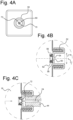
- FIG 4A shows the front view of the cartridge 10 with the cap 50 and cross valve 60.
- the valve 60 is placed over the cap opening 54.
- the valve 60 is the silicon cross piece 70.
- This valve has four flaps 72 formed by two perpendicular slits extending through the center of the silicon cross piece 70.
- Figure 4B shows the cross-sectional view of the cap 50 with the silicon cross piece 70.
- the cap opening 54 is bound in the radial direction by an edge of the opening 56.
- the flaps 72 extend in a radial direction R from a central axis C of the cap opening 54 towards an edge of the opening 56.
- FIG. 4C illustrates the situation when the cap 50 is connected to the negative pressure device 44 of the cleaning appliance. Under the negative pressure, the flaps 72 open and the liquid conduit 24 is formed between the cleaning product space 16 and the cleaning appliance, shown by the flow arrows.
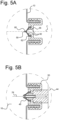
- FIG 5A illustrates a preferred type of the valve, the duckbill valve 80.
- the duckbill valve 80 is placed over the cap opening 54 and fastened to the edge of the opening 56 by the pressure ring 62.
- the duckbill valve has two flaps 82 which form a seal 59 around the central axis C of the cap when the cartridge 10 is not in use to prevent spillage of the cleaning product 42.
- Figure 5B shows the cap 50 when connected to the negative pressure device 44 of the cleaning appliance 200.
- the negative pressure device 44 has an injection pin 46 which opens the seal 59 to form the liquid conduit 24 between the cleaning product space 16 and the cleaning appliance 200. The contents then flow from inside the cartridge 10 out the valve 80 and cap 50 for use.
- the cartridge 10 When in use, the cartridge 10 is connected to the negative pressure device 44 via the cap 50, as illustrated in Figure 6B .
- the injection pin 46 of the negative pressure device 44 applies a force and deforms the ball 90.
- the ball 90 is deformed such that it moves away from the closing ring 94, and allows for flow through the flow openings 92.
- the liquid conduit 24 is formed from the cleaning product space 16, through the flow openings 92 and the ball space 58, to the negative pressure device 44.
Landscapes
- Engineering & Computer Science (AREA)
- Mechanical Engineering (AREA)
- Containers And Packaging Bodies Having A Special Means To Remove Contents (AREA)
- Packages (AREA)
- Closures For Containers (AREA)
- Check Valves (AREA)
Claims (12)
- Kappe (50) für eine Kartusche (10), wobei die Kappe Folgendes umfasst:Befestigungsmittel (52) zum Befestigen der Kappe (50) an einer Kartuschenöffnung (36); undein Ventil (60), das konfiguriert ist, eine Flüssigkeitsströmung vom Inneren der Kartusche (10) durch die Kartuschenöffnung (36) und die Kappe (50) bei Unterdruck zu steuern,dadurch gekennzeichnet, dassdas Ventil (60) eine verformbare Kugel (90) ist, die eine oder mehrere Strömungsöffnungen (92) in einem nicht verformten Zustand (NS) bedeckt und sich verformt, um eine Strömung durch die eine oder mehrere Strömungsöffnungen (92) im verformten Zustand (DS) zu ermöglichen.
- Kappe (50) nach Anspruch 1, wobei die Kappe (50) ferner einen Druckring (62) zum Befestigen eines oder mehrerer Ventilteile umfasst.
- Kappe (50) nach Anspruch 1 oder Anspruch 2, wobei die Befestigungsmittel (52) ein Gewinde, eine Rille, einen Ansatz und/oder ein anderes Verbindungsteil umfasst.
- Kappe (50) nach einem der Ansprüche 1 bis 3, wobei die eine oder die mehreren Strömungsöffnungen (92) von einer Mittelachse (C) der Kappe (50) in einer radialen Richtung (R) verlaufen.
- Kappe (50) nach einem der vorhergehenden Ansprüche, wobei die Kugel (90) Silikon oder Gummi umfasst.
- Kappe (50) nach einem der vorhergehenden Ansprüche, wobei sich die Kugel (90) durch Druckkräfte verformt.
- Kappe (50) nach Anspruch 6, wobei die Druckkräfte von einem Einspritzstift (46) herrühren.
- Kartusche (10), die Folgendes umfasst:einen starren Außenkörper (12);einen elastischen Innenkörper (14), der wenigstens teilweise im Außenkörper (12) angeordnet ist;eine Kartuschenöffnung (36); undeine Kappe (50) nach Anspruch 1 für die Kartusche.
- Kartusche (10) nach Anspruch 8, wobei sich das Ventil (60) der Kappe (50) zum Steuern einer Flüssigkeitsströmung vom elastischen Innenkörper (14) durch die Kartuschenöffnung (36) und die Kappe (50) wenigstens teilweise über die Kartuschenöffnung (36) hinaus erstreckt.
- Kartusche (10) nach Anspruch 8 oder Anspruch 9, wobei die eine oder die mehreren Strömungsöffnungen (92) von einer Mittelachse (C) der Kappe (50) in einer radialen Richtung (R) verlaufen.
- Kartusche (10) nach Anspruch 10, wobei sich die Kugel (90) durch Druckkräfte verformt, wobei die Druckkräfte vorzugsweise von einem Einspritzstift (46) herrühren.
- Kartusche (10) nach einem der Ansprüche 8 bis 11, wobei die Kartusche (10) so konfiguriert ist, dass sie in ein Reinigungsgerät (200) eingesetzt wird.
Applications Claiming Priority (3)
| Application Number | Priority Date | Filing Date | Title |
|---|---|---|---|
| CN2021132349 | 2021-11-23 | ||
| EP21215242 | 2021-12-16 | ||
| PCT/EP2022/081870 WO2023094203A1 (en) | 2021-11-23 | 2022-11-15 | Cap with valve for cartridge |
Publications (3)
| Publication Number | Publication Date |
|---|---|
| EP4436893A1 EP4436893A1 (de) | 2024-10-02 |
| EP4436893B1 true EP4436893B1 (de) | 2025-05-21 |
| EP4436893C0 EP4436893C0 (de) | 2025-05-21 |
Family
ID=84421257
Family Applications (1)
| Application Number | Title | Priority Date | Filing Date |
|---|---|---|---|
| EP22818256.4A Active EP4436893B1 (de) | 2021-11-23 | 2022-11-15 | Kappe mit ventil für kartusche |
Country Status (4)
| Country | Link |
|---|---|
| US (1) | US20240417144A1 (de) |
| EP (1) | EP4436893B1 (de) |
| JP (1) | JP2024543870A (de) |
| WO (1) | WO2023094203A1 (de) |
Family Cites Families (5)
| Publication number | Priority date | Publication date | Assignee | Title |
|---|---|---|---|---|
| US5301838A (en) * | 1991-01-23 | 1994-04-12 | Continental Pet Technologies, Inc. | Multilayer bottle with separable inner layer and method for forming same |
| TR201802342T4 (tr) | 2013-02-04 | 2018-03-21 | Anthony Bradley Mark | İçeriğin verilmesini kolaylaştırmak için sökülemeyen kapaklı kap. |
| CN108998931A (zh) | 2018-09-27 | 2018-12-14 | 青岛海尔洗衣机有限公司 | 家用电器外置储液盒及家用电器 |
| CN111270480A (zh) | 2020-02-07 | 2020-06-12 | 青岛海尔洗衣机有限公司 | 一种单向透气结构、洗涤添加剂盒及洗涤设备 |
| CN112900012A (zh) | 2020-12-04 | 2021-06-04 | 杭州神林电子有限公司 | 一种自动投放用洗涤剂盒 |
-
2022
- 2022-11-15 US US18/712,696 patent/US20240417144A1/en active Pending
- 2022-11-15 WO PCT/EP2022/081870 patent/WO2023094203A1/en not_active Ceased
- 2022-11-15 EP EP22818256.4A patent/EP4436893B1/de active Active
- 2022-11-15 JP JP2024529883A patent/JP2024543870A/ja active Pending
Also Published As
| Publication number | Publication date |
|---|---|
| US20240417144A1 (en) | 2024-12-19 |
| EP4436893A1 (de) | 2024-10-02 |
| JP2024543870A (ja) | 2024-11-26 |
| WO2023094203A1 (en) | 2023-06-01 |
| EP4436893C0 (de) | 2025-05-21 |
Similar Documents
| Publication | Publication Date | Title |
|---|---|---|
| CN101952177B (zh) | 具有防止狭缝未对准的特征的阀安装组件 | |
| KR101378369B1 (ko) | 펌핑식 화장품용기 | |
| EP2295022B1 (de) | Austragsbehälter mit filter | |
| US6874656B2 (en) | Vented closure | |
| KR200490671Y1 (ko) | 에코 펌프 방식의 화장품 용기 | |
| CZ20012022A3 (cs) | Nevytékavý uzávěr a dávkovací obal na tekutiny | |
| US8678246B2 (en) | Cartridge and piston with ventilation device | |
| KR102091210B1 (ko) | 에코 펌프 방식의 화장품 용기 | |
| EP2344398B1 (de) | Torverschlusssystem mit hammerwiderstand | |
| EP2835322B1 (de) | Tube zur verhinderung einer luftinfiltration | |
| EP4436893B1 (de) | Kappe mit ventil für kartusche | |
| US20250011062A1 (en) | Container with flexible inner body | |
| EP1721542A2 (de) | Verbesserte Behälterverschlusseinrichtung eines Flüssigkeitsspenders | |
| CN217919330U (zh) | 容器 | |
| CN218949936U (zh) | 筒以及用于筒的罩盖 | |
| US20250162784A1 (en) | Container with flexible portion | |
| KR101584718B1 (ko) | 단부 가압식 펌핑용기 | |
| US20100059553A1 (en) | Tube-type container having check function | |
| JP4599035B2 (ja) | 試料搬送用ジャグ | |
| KR102297663B1 (ko) | 펌프 용기 | |
| KR200493057Y1 (ko) | 화장품 용기용 에코 펌프 | |
| CN221050421U (zh) | 用于筒的盖、抽吸和通气系统、筒、配给系统和清洁器具 | |
| CN218232851U (zh) | 一种洗涤剂容纳装置、洗涤剂投放结构及洗涤设备 | |
| CN220148034U (zh) | 具有柔性部分的容器 | |
| WO2024217789A1 (en) | Cap with valves for cartridge |
Legal Events
| Date | Code | Title | Description |
|---|---|---|---|
| STAA | Information on the status of an ep patent application or granted ep patent |
Free format text: STATUS: UNKNOWN |
|
| STAA | Information on the status of an ep patent application or granted ep patent |
Free format text: STATUS: THE INTERNATIONAL PUBLICATION HAS BEEN MADE |
|
| PUAI | Public reference made under article 153(3) epc to a published international application that has entered the european phase |
Free format text: ORIGINAL CODE: 0009012 |
|
| STAA | Information on the status of an ep patent application or granted ep patent |
Free format text: STATUS: REQUEST FOR EXAMINATION WAS MADE |
|
| 17P | Request for examination filed |
Effective date: 20240408 |
|
| AK | Designated contracting states |
Kind code of ref document: A1 Designated state(s): AL AT BE BG CH CY CZ DE DK EE ES FI FR GB GR HR HU IE IS IT LI LT LU LV MC ME MK MT NL NO PL PT RO RS SE SI SK SM TR |
|
| GRAP | Despatch of communication of intention to grant a patent |
Free format text: ORIGINAL CODE: EPIDOSNIGR1 |
|
| STAA | Information on the status of an ep patent application or granted ep patent |
Free format text: STATUS: GRANT OF PATENT IS INTENDED |
|
| DAV | Request for validation of the european patent (deleted) | ||
| DAX | Request for extension of the european patent (deleted) | ||
| INTG | Intention to grant announced |
Effective date: 20250204 |
|
| GRAS | Grant fee paid |
Free format text: ORIGINAL CODE: EPIDOSNIGR3 |
|
| GRAA | (expected) grant |
Free format text: ORIGINAL CODE: 0009210 |
|
| STAA | Information on the status of an ep patent application or granted ep patent |
Free format text: STATUS: THE PATENT HAS BEEN GRANTED |
|
| AK | Designated contracting states |
Kind code of ref document: B1 Designated state(s): AL AT BE BG CH CY CZ DE DK EE ES FI FR GB GR HR HU IE IS IT LI LT LU LV MC ME MK MT NL NO PL PT RO RS SE SI SK SM TR |
|
| REG | Reference to a national code |
Ref country code: GB Ref legal event code: FG4D |
|
| REG | Reference to a national code |
Ref country code: CH Ref legal event code: EP |
|
| REG | Reference to a national code |
Ref country code: IE Ref legal event code: FG4D |
|
| U01 | Request for unitary effect filed |
Effective date: 20250521 |
|
| U07 | Unitary effect registered |
Designated state(s): AT BE BG DE DK EE FI FR IT LT LU LV MT NL PT RO SE SI Effective date: 20250527 |
|
| RAP4 | Party data changed (patent owner data changed or rights of a patent transferred) |
Owner name: UNILEVER IP HOLDINGS B.V. Owner name: UNILEVER GLOBAL IP LIMITED |
|
| U1H | Name or address of the proprietor changed after the registration of the unitary effect |
Owner name: UNILEVER IP HOLDINGS B.V.; NL Owner name: UNILEVER GLOBAL IP LIMITED; GB |
|
| PG25 | Lapsed in a contracting state [announced via postgrant information from national office to epo] |
Ref country code: ES Free format text: LAPSE BECAUSE OF FAILURE TO SUBMIT A TRANSLATION OF THE DESCRIPTION OR TO PAY THE FEE WITHIN THE PRESCRIBED TIME-LIMIT Effective date: 20250521 |
|
| PG25 | Lapsed in a contracting state [announced via postgrant information from national office to epo] |
Ref country code: NO Free format text: LAPSE BECAUSE OF FAILURE TO SUBMIT A TRANSLATION OF THE DESCRIPTION OR TO PAY THE FEE WITHIN THE PRESCRIBED TIME-LIMIT Effective date: 20250821 Ref country code: GR Free format text: LAPSE BECAUSE OF FAILURE TO SUBMIT A TRANSLATION OF THE DESCRIPTION OR TO PAY THE FEE WITHIN THE PRESCRIBED TIME-LIMIT Effective date: 20250822 |
|
| PG25 | Lapsed in a contracting state [announced via postgrant information from national office to epo] |
Ref country code: PL Free format text: LAPSE BECAUSE OF FAILURE TO SUBMIT A TRANSLATION OF THE DESCRIPTION OR TO PAY THE FEE WITHIN THE PRESCRIBED TIME-LIMIT Effective date: 20250521 |
|
| PG25 | Lapsed in a contracting state [announced via postgrant information from national office to epo] |
Ref country code: HR Free format text: LAPSE BECAUSE OF FAILURE TO SUBMIT A TRANSLATION OF THE DESCRIPTION OR TO PAY THE FEE WITHIN THE PRESCRIBED TIME-LIMIT Effective date: 20250521 |
|
| PG25 | Lapsed in a contracting state [announced via postgrant information from national office to epo] |
Ref country code: RS Free format text: LAPSE BECAUSE OF FAILURE TO SUBMIT A TRANSLATION OF THE DESCRIPTION OR TO PAY THE FEE WITHIN THE PRESCRIBED TIME-LIMIT Effective date: 20250821 |
|
| PG25 | Lapsed in a contracting state [announced via postgrant information from national office to epo] |
Ref country code: IS Free format text: LAPSE BECAUSE OF FAILURE TO SUBMIT A TRANSLATION OF THE DESCRIPTION OR TO PAY THE FEE WITHIN THE PRESCRIBED TIME-LIMIT Effective date: 20250921 |
|
| PG25 | Lapsed in a contracting state [announced via postgrant information from national office to epo] |
Ref country code: SM Free format text: LAPSE BECAUSE OF FAILURE TO SUBMIT A TRANSLATION OF THE DESCRIPTION OR TO PAY THE FEE WITHIN THE PRESCRIBED TIME-LIMIT Effective date: 20250521 |
|
| PG25 | Lapsed in a contracting state [announced via postgrant information from national office to epo] |
Ref country code: CZ Free format text: LAPSE BECAUSE OF FAILURE TO SUBMIT A TRANSLATION OF THE DESCRIPTION OR TO PAY THE FEE WITHIN THE PRESCRIBED TIME-LIMIT Effective date: 20250521 |
|
| PG25 | Lapsed in a contracting state [announced via postgrant information from national office to epo] |
Ref country code: SK Free format text: LAPSE BECAUSE OF FAILURE TO SUBMIT A TRANSLATION OF THE DESCRIPTION OR TO PAY THE FEE WITHIN THE PRESCRIBED TIME-LIMIT Effective date: 20250521 |
|
| U1N | Appointed representative for the unitary patent procedure changed after the registration of the unitary effect |
Representative=s name: UNILEVER PATENT GROUP; NL |
|
| PLBE | No opposition filed within time limit |
Free format text: ORIGINAL CODE: 0009261 |
|
| STAA | Information on the status of an ep patent application or granted ep patent |
Free format text: STATUS: NO OPPOSITION FILED WITHIN TIME LIMIT |
|
| REG | Reference to a national code |
Ref country code: CH Ref legal event code: L10 Free format text: ST27 STATUS EVENT CODE: U-0-0-L10-L00 (AS PROVIDED BY THE NATIONAL OFFICE) Effective date: 20260402 |