EP4436201B1 - Battery pack - Google Patents
Battery pack Download PDFInfo
- Publication number
- EP4436201B1 EP4436201B1 EP23212452.9A EP23212452A EP4436201B1 EP 4436201 B1 EP4436201 B1 EP 4436201B1 EP 23212452 A EP23212452 A EP 23212452A EP 4436201 B1 EP4436201 B1 EP 4436201B1
- Authority
- EP
- European Patent Office
- Prior art keywords
- battery
- battery pack
- signal
- control device
- structures
- Prior art date
- Legal status (The legal status is an assumption and is not a legal conclusion. Google has not performed a legal analysis and makes no representation as to the accuracy of the status listed.)
- Active
Links
Images


Classifications
-
- H—ELECTRICITY
- H04—ELECTRIC COMMUNICATION TECHNIQUE
- H04Q—SELECTING
- H04Q9/00—Arrangements in telecontrol or telemetry systems for selectively calling a substation from a main station, in which substation desired apparatus is selected for applying a control signal thereto or for obtaining measured values therefrom
-
- G—PHYSICS
- G01—MEASURING; TESTING
- G01R—MEASURING ELECTRIC VARIABLES; MEASURING MAGNETIC VARIABLES
- G01R31/00—Arrangements for testing electric properties; Arrangements for locating electric faults; Arrangements for electrical testing characterised by what is being tested not provided for elsewhere
- G01R31/36—Arrangements for testing, measuring or monitoring the electrical condition of accumulators or electric batteries, e.g. capacity or state of charge [SoC]
- G01R31/371—Arrangements for testing, measuring or monitoring the electrical condition of accumulators or electric batteries, e.g. capacity or state of charge [SoC] with remote indication, e.g. on external chargers
-
- G—PHYSICS
- G01—MEASURING; TESTING
- G01R—MEASURING ELECTRIC VARIABLES; MEASURING MAGNETIC VARIABLES
- G01R31/00—Arrangements for testing electric properties; Arrangements for locating electric faults; Arrangements for electrical testing characterised by what is being tested not provided for elsewhere
- G01R31/36—Arrangements for testing, measuring or monitoring the electrical condition of accumulators or electric batteries, e.g. capacity or state of charge [SoC]
- G01R31/385—Arrangements for measuring battery or accumulator variables
-
- H—ELECTRICITY
- H01—ELECTRIC ELEMENTS
- H01M—PROCESSES OR MEANS, e.g. BATTERIES, FOR THE DIRECT CONVERSION OF CHEMICAL ENERGY INTO ELECTRICAL ENERGY
- H01M10/00—Secondary cells; Manufacture thereof
- H01M10/42—Methods or arrangements for servicing or maintenance of secondary cells or secondary half-cells
- H01M10/4207—Methods or arrangements for servicing or maintenance of secondary cells or secondary half-cells for several batteries or cells simultaneously or sequentially
-
- H—ELECTRICITY
- H01—ELECTRIC ELEMENTS
- H01M—PROCESSES OR MEANS, e.g. BATTERIES, FOR THE DIRECT CONVERSION OF CHEMICAL ENERGY INTO ELECTRICAL ENERGY
- H01M10/00—Secondary cells; Manufacture thereof
- H01M10/42—Methods or arrangements for servicing or maintenance of secondary cells or secondary half-cells
- H01M10/425—Structural combination with electronic components, e.g. electronic circuits integrated to the outside of the casing
-
- H—ELECTRICITY
- H01—ELECTRIC ELEMENTS
- H01M—PROCESSES OR MEANS, e.g. BATTERIES, FOR THE DIRECT CONVERSION OF CHEMICAL ENERGY INTO ELECTRICAL ENERGY
- H01M10/00—Secondary cells; Manufacture thereof
- H01M10/42—Methods or arrangements for servicing or maintenance of secondary cells or secondary half-cells
- H01M10/48—Accumulators combined with arrangements for measuring, testing or indicating the condition of cells, e.g. the level or density of the electrolyte
- H01M10/482—Accumulators combined with arrangements for measuring, testing or indicating the condition of cells, e.g. the level or density of the electrolyte for several batteries or cells simultaneously or sequentially
-
- H—ELECTRICITY
- H01—ELECTRIC ELEMENTS
- H01M—PROCESSES OR MEANS, e.g. BATTERIES, FOR THE DIRECT CONVERSION OF CHEMICAL ENERGY INTO ELECTRICAL ENERGY
- H01M50/00—Constructional details or processes of manufacture of the non-active parts of electrochemical cells other than fuel cells, e.g. hybrid cells
- H01M50/20—Mountings; Secondary casings or frames; Racks, modules or packs; Suspension devices; Shock absorbers; Transport or carrying devices; Holders
- H01M50/204—Racks, modules or packs for multiple batteries or multiple cells
-
- H—ELECTRICITY
- H01—ELECTRIC ELEMENTS
- H01Q—ANTENNAS, i.e. RADIO AERIALS
- H01Q1/00—Details of, or arrangements associated with, antennas
- H01Q1/12—Supports; Mounting means
- H01Q1/22—Supports; Mounting means by structural association with other equipment or articles
-
- H—ELECTRICITY
- H01—ELECTRIC ELEMENTS
- H01Q—ANTENNAS, i.e. RADIO AERIALS
- H01Q1/00—Details of, or arrangements associated with, antennas
- H01Q1/36—Structural form of radiating elements, e.g. cone, spiral, umbrella; Particular materials used therewith
- H01Q1/38—Structural form of radiating elements, e.g. cone, spiral, umbrella; Particular materials used therewith formed by a conductive layer on an insulating support
-
- H—ELECTRICITY
- H01—ELECTRIC ELEMENTS
- H01Q—ANTENNAS, i.e. RADIO AERIALS
- H01Q17/00—Devices for absorbing waves radiated from an antenna; Combinations of such devices with active antenna elements or systems
- H01Q17/008—Devices for absorbing waves radiated from an antenna; Combinations of such devices with active antenna elements or systems with a particular shape
-
- H02J7/40—
-
- H02J7/44—
-
- H02J7/50—
-
- H—ELECTRICITY
- H01—ELECTRIC ELEMENTS
- H01M—PROCESSES OR MEANS, e.g. BATTERIES, FOR THE DIRECT CONVERSION OF CHEMICAL ENERGY INTO ELECTRICAL ENERGY
- H01M10/00—Secondary cells; Manufacture thereof
- H01M10/42—Methods or arrangements for servicing or maintenance of secondary cells or secondary half-cells
- H01M10/425—Structural combination with electronic components, e.g. electronic circuits integrated to the outside of the casing
- H01M2010/4271—Battery management systems including electronic circuits, e.g. control of current or voltage to keep battery in healthy state, cell balancing
-
- H—ELECTRICITY
- H01—ELECTRIC ELEMENTS
- H01M—PROCESSES OR MEANS, e.g. BATTERIES, FOR THE DIRECT CONVERSION OF CHEMICAL ENERGY INTO ELECTRICAL ENERGY
- H01M10/00—Secondary cells; Manufacture thereof
- H01M10/42—Methods or arrangements for servicing or maintenance of secondary cells or secondary half-cells
- H01M10/425—Structural combination with electronic components, e.g. electronic circuits integrated to the outside of the casing
- H01M2010/4278—Systems for data transfer from batteries, e.g. transfer of battery parameters to a controller, data transferred between battery controller and main controller
-
- H—ELECTRICITY
- H04—ELECTRIC COMMUNICATION TECHNIQUE
- H04Q—SELECTING
- H04Q2209/00—Arrangements in telecontrol or telemetry systems
- H04Q2209/40—Arrangements in telecontrol or telemetry systems using a wireless architecture
-
- H—ELECTRICITY
- H04—ELECTRIC COMMUNICATION TECHNIQUE
- H04Q—SELECTING
- H04Q2209/00—Arrangements in telecontrol or telemetry systems
- H04Q2209/40—Arrangements in telecontrol or telemetry systems using a wireless architecture
- H04Q2209/43—Arrangements in telecontrol or telemetry systems using a wireless architecture using wireless personal area networks [WPAN], e.g. 802.15, 802.15.1, 802.15.4, Bluetooth or ZigBee
-
- Y—GENERAL TAGGING OF NEW TECHNOLOGICAL DEVELOPMENTS; GENERAL TAGGING OF CROSS-SECTIONAL TECHNOLOGIES SPANNING OVER SEVERAL SECTIONS OF THE IPC; TECHNICAL SUBJECTS COVERED BY FORMER USPC CROSS-REFERENCE ART COLLECTIONS [XRACs] AND DIGESTS
- Y02—TECHNOLOGIES OR APPLICATIONS FOR MITIGATION OR ADAPTATION AGAINST CLIMATE CHANGE
- Y02E—REDUCTION OF GREENHOUSE GAS [GHG] EMISSIONS, RELATED TO ENERGY GENERATION, TRANSMISSION OR DISTRIBUTION
- Y02E60/00—Enabling technologies; Technologies with a potential or indirect contribution to GHG emissions mitigation
- Y02E60/10—Energy storage using batteries
Definitions
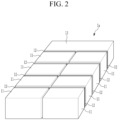
- the rechargeable battery is used in the form of a battery module including a plurality of unit battery cells connected in series and/or in parallel, thereby providing high energy density for running, e.g., a hybrid vehicle. That is, the battery module is, for example, formed by interconnecting electrode terminals of a plurality of unit battery cells according to an amount of power required to implement a high-power rechargeable battery for an electric vehicle.
- One or more battery modules are mechanically and electrically integrated to form a battery system.
- SoC state of charge
- An embodiment of the present disclosure provides a battery pack including: a plurality of battery modules, each including at least one cell and a control device for managing the at least one cell; a main control device configured to wirelessly communicate with each of the control devices; and a plurality of structures each corresponding to one of the plurality of battery modules, each of the structures being configured to adjust signal intensity of a respective radio signal transmitted to the main control device from the control device of the corresponding battery module from among the plurality of battery modules.
- Each of the structures may comprise a conductive material that adjusts the signal intensity of the respective radio signal passing through the conductive material through at least one of: reflection, scattering, diffraction, and absorption of electromagnetic waves of the radio signals by the conductive material.
- the plurality of structures may be configured so that antenna patterns of the antenna modules differ in at least one of size, area, component, and shape.
- Each of the plurality of structures may includes a noise generator for generating a noise signal for the respective radio signal.
- the plurality of structures may be configured so that output power or output intensity of the noise signals output by the noise generators are different from each other.
- a battery pack including: a plurality of battery modules, each including at least one cell and a control device for managing the at least one cell; a main control device configured to wirelessly communicate with each of the control devices; and a plurality of signal generating modules, each corresponding to one of the plurality of battery modules, and being configured to generate a voltage signal having a voltage value that depends upon a position or a connection order of the corresponding battery module from among the plurality of battery modules.
- the respective control device may be further configured to acquire position identification information based on the voltage signal of the corresponding signal generating module from among the plurality of signal generating modules, and to transmit a radio signal including the position identification information to the main control device.
- the main control device may be the further configured to identify positions or a connection order of the plurality of battery modules based on the position identification information detected from the radio signal.
- Each of the plurality of signal generating modules may include a voltage dividing circuit for generating the voltage signal.
- Each of the plurality of voltage dividing circuits may include a plurality of resistors, wherein for different ones of the plurality of voltage dividing circuits, resistances of resistors are different from each other.
- Each of the plurality of signal generating modules may further include an analog-to-digital converter for transmitting the voltage signal to the control device of the corresponding battery pack.
- the position of the battery module may be detected when communication between the control devices in the battery pack is performed wirelessly.
- the term “and/or” includes any and all combinations of one or more related listed items.
- the use of "can/may” in describing an embodiment of the present disclosure indicates “at least one embodiment of the present disclosure.”
- first and second are used to describe various elements, but these elements should not be limited by these terms. These terms are only used to distinguish one element from another.
- a first constituent element may be referred to as a second constituent element, and the second constituent element may be referred to as the first constituent element without departing from the scope of the present disclosure.
- the term “and/or” includes any and all combinations of one or more related listed items. An expression such as "at least one" precedes a list of elements, modifying the entire list of elements and not individual elements of the list.
- the terms “substantially”, “approximately”, and similar terms are used as approximate terms but are not used as degree terms, and they are not intended to illustrate inherent deviations of measured or calculated values evident to those skilled in the art.
- the term “substantially” refers to including a range of +/-5 % of the value.
- Electric connection of two constituent elements includes not only a case where the two constituent elements are directly connected, but also a case where the two constituent elements are connected through another constituent element interposed therebetween.
- Other constituent elements may include a switch, a resistor, a capacitor, and the like.
- connection means electrical connection unless there is an expression "direct connection”.
- the control module 13 may include a main control device (refer to the main BMS 131 of FIG. 1 ) for controlling general operations such as charge and discharge, balancing, diagnosis of the battery pack 1a.
- Equation 1 expresses a method for calculating a signal-to-noise ratio (SNR) for the respective main BMSs 131 to determine intensity (i.e., sensitivity) of the signals received from the respective BMMs 112.
- SNR dB 10 log 10 P S N S
- P S represents average signal power
- N S indicates average noise power
- the respective structures 12 may be configured to increase N S .
- N S generated by the respective structures 12 may be different depending on the position (or the connection order) of the battery module 11 corresponding to - 30dBm, -33dBm, -36dBm, -39dBm, -42dBm, -45dBm, -48dBm, and -50dBm.
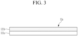
- Each structure 12 may include a shield filter for adjusting radio signal intensity by using an electromagnetic wave characteristic.
- FIG. 3 shows a cross-sectional view of a shield filter according to an embodiment.
- the shield filter 12a may include a substrate 121a and a conductive material 121b disposed on one side of the substrate 121a.
- the shield filter 12a may adjust the signal intensity of radio signals passing through the shield filter through reflection, scattering, diffraction, and absorption of electromagnetic waves by the conductive material 121b.
- the conductive material 121b may include an amorphous alloy. Surface shapes, components, and thicknesses of the conductive material 121b of the shield filters 12a may be differently configured in order to vary the adjustment degrees of signal intensity according to the position (or a connection order) of the corresponding battery module 11 in the battery pack 1a.
- the respective structures 12 may be antenna structures for transmitting radio signals to the main BMS 131 from the respective BMMs 112.
- the respective structures 12 are connected to a communication device of the corresponding BMM 112, and may wirelessly transmit signals generated by the respective BMMs 112 to the main BMS 131.
- FIG. 4 shows a cross-sectional view of an antenna structure according to an embodiment.
- the antenna structure 12b may include a substrate 122a, and an antenna pattern 122b disposed on one side of the substrate 122a.
- the antenna pattern 122b may include a conductive wire disposed in a specific shape. Sizes, areas, components, and shapes of the antenna pattern 122b of the antenna structure 12b may be differently configured in order to vary the adjustment degrees of signal intensity according to the position (or the connection order) of the corresponding battery module 11 in the battery pack 1a.
- the respective structures 12 may include a noise generator (not shown) for applying jamming signals (or noise signals) for signals transmitted to the main BMS 131 from the respective BMMs 112.
- the noise generator may be configured to output a noise signal having different output power (or output intensity) according to a disposed position (or a connection order) of the corresponding battery module 11 in the battery pack 1a.
- the noise generator may be connected to the antenna module of the respective BMMs 112 and may directly apply a noise signal to the antenna module.
- the noise generator may apply the noise signal according to a signal interference method, regarding the radio signal transmitted from the antenna module of the respective BMMs 112.
- the radio signals transmitted from the respective BMMs 112 may be received by the main BMS 131, with the signal intensity thereof adjusted by the respective structures 12. Therefore, when receiving radio signals from the respective BMMs 112, the main BMS 131 identifies from which battery module 11 the corresponding radio signal is transmitted from among identification information included in the radio signals (i.e., identification information of the respective BMMs 112), and may identify the position (or the connection order) of the corresponding battery module 11 based on the received signal intensity of the radio signals.
- identification information included in the radio signals i.e., identification information of the respective BMMs 112
- the radio signals transmitted to the main BMS 131 from the respective BMMs 112 may have slightly different received signal intensities.
- the difference in received signal intensity due to the difference in the positions of the respective battery modules 11 may be very minute, and the main BMS 131 may have difficulty in identifying the same. Therefore, in this embodiment, as described above, discrimination in the main BMS 131 may be increased by artificially adjusting the received signal intensities using structure 12 to increase the difference in received signal intensities for the different BMMs 112.
- the structure 12 that adjusts signal intensity separately from the battery module 11 it is not necessary to change the structure of the battery modules 11 or a setting value of the BMM 112 for the purpose of identifying positions in the manufacturing process, and the battery module 11 may be replaced without any additional work for identifying positions.
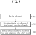
- FIG. 5 shows a flowchart of a method for identifying positions of respective battery modules in a battery pack according to an embodiment.
- the method of FIG. 5 may be performed by the main BMS 131 of the battery pack 1a described with reference to FIG. 1 to FIG. 4 .
- the main BMS 131 may detect identification information (identification information of the BMM having transmitted the corresponding radio signal) and received signal intensity from the received signal (S12). In addition, the main BMS 131 may identify the battery module 11 having transmitted the corresponding signal based on the identification information detected from the received signal, and may determine the position (or the connection order) of the corresponding battery module 11 based on the detected received signal intensity (S13).
- the respective BMMs 112 may include their identification information in the signal and may transmit the same. Accordingly, the main BMS 131 may detect identification information from the received signal and may identify the corresponding BMM 112 and the battery module 11 including the same according to the detected identification information.
- the signals transmitted from the respective BMMs 112 may be transmitted to the main BMS 131 with the signal intensity adjusted by the corresponding structure 12.
- the adjustment degrees of signal intensity by the structures 12 may vary according to the position (or the connection order) of the battery module 11 corresponding to the respective structures 12. Therefore, the main BMS 131 may identify the corresponding BMM 112 and the position (or the connection order) of the battery module 11 including the corresponding BMM 112 according to the received signal intensity detected from the received signal. To this end, the main BMS 131 may predetermine and store a range of the received signal intensity corresponding to the position (or the connection order) of the battery module 11. The main BMS 131 may determine the position (or the connection order) of the corresponding battery module 11 by checking which position (or the connection order) in the range of the received signal intensity the received signal intensity range of the received signal is included in.
- FIG. 6 shows a configuration diagram of a battery pack according to another embodiment
- FIG. 7 shows a configuration diagram of a signal generating circuit of FIG. 6 .
- the battery pack 1b may include a plurality of battery modules 11 and a control module 13.
- the respective battery modules 11 may include a cell assembly 111 including at least one cell connected to each other in series and/or in parallel, and a control device (refer to the BMM 112 of FIG. 6 ) for monitoring and managing states (voltage, current, temperature, etc.,) of the corresponding cell assembly 111.
- the battery pack 1b may further include a signal generating module 14 for generating a signal whose value varies according to a position (or a connection order) of the corresponding battery module 11.
- the signal generating module 14 may include a voltage generating circuit 141 and an analog-to-digital converter (ADC) 142.
- the voltage generating circuit 141 may generate a voltage signal whose voltage value varies according to a position (or a connection order) of the corresponding battery module 11.
- the voltage generating circuit 141 may include a voltage dividing circuit including a plurality of resistors. In this case, resistances of the resistors constituting the voltage generating circuit 141 may vary according to the position (or a connection order) of the corresponding battery module 11.
- the ADC 142 may convert the voltage signal generated by the voltage generating circuit 141 into a digital signal and may transmit the digital signal to a corresponding controller (not shown) of the BMM 112.
- the controller of the BMM 112 may generate position identification information (e.g., a media access control (MAC) address, etc.) for indicating the position (or the connection order) of the corresponding battery module 11 according to the output signal of the ADC 142.
- the respective BMMs 112 may transmit a radio signal including the generated position identification information and its own identification information to the main BMS 131.
- the main BMS 131 may identify the battery module 11 having transmitted the corresponding radio signal based on the identification information (BMM identification information and position identification information) detected therefrom, and the position (or the connection order) of the corresponding battery module 11.
- the respective main BMSs 131 may predetermine and store position identification information corresponding to the position of the battery module 11.
- the main BMS 131 may determine the position of the corresponding battery module 11 by comparing position identification information detected from the received signal and stored position identification information.
- FIG. 7 shows the case where the signal generating module 14 includes the ADC 142 as an example, but the signal generating module 14 may be modified to include the voltage generating circuit 141.
- the voltage signal generated by the voltage generating circuit 141 may be input to an ADC included in the corresponding BMM 112 or in the controller of the BMM 112.
- FIG. 8 shows a flowchart of a method for identifying positions of respective battery modules in a battery pack according to another embodiment.
- the method of FIG. 8 may be performed by the main BMS 131 of the battery pack 1b described with reference to FIG. 6 and FIG. 7 .
- the main BMS 131 may detect identification information and position identification information of the corresponding BMM 112 from the received signal (S22). The main BMS 131 may identify the battery module 11 having transmitted the signal based on the identification information (BMM identification information and position identification information) detected from the received signal, and may identify the position (or the connection order) of the corresponding battery module 11 based on the detected received signal intensity (S23).
- the BMMs 112 may generate position identification information indicating the position of the corresponding battery module 11 based on the output signal of the signal generating module 14 for generating a voltage signal whose voltage value varies according to the position of the corresponding battery module 11.
- the respective BMMs 112 may transmit the position identification information generated in this way to the main BMS 131 along with its own identification information.
- Electronic or electrical devices according to embodiments of the present invention and/or other related devices or constituent elements may be realized by using appropriate hardware, firmware (e.g., an application-specific integrated circuit), software, or combinations of software, firmware, and hardware.
- firmware e.g., an application-specific integrated circuit
- various configurations of the above-noted devices may be positioned on one integrated circuit (IC) chip or an individual IC chip.
- Various configurations of the above-noted devices may be realized on a flexible printed circuit film, a tape carrier package (TCP), a printed circuit board (PCB), or one substrate.
- the electrical or mutual connections described in the present specification may, for example, be realized by the PCB, wires on different types of circuit carriers, or conductive elements.
- the conductive elements may, for example, include metallization such as surface metallization and/or pins, and may include conductive polymers or ceramics. Electrical energy may be transmitted by electromagnetic radiation or a light-using radio access.
- the various configurations of the devices may be performed by at least one processor so as to perform the above-described various functions, they may be performed in at least one computing device, and they may be processes or threads for performing computer program instructions and interacting with other system constituent elements.
- the computer program instruction is stored in a memory realizable in a computing device using a standard memory device such as a random access memory (RAM).
- the computer program instruction may also be stored in a non-transitory computer readable medium such as a CD-ROM or a flash drive.
Landscapes
- Engineering & Computer Science (AREA)
- Chemical & Material Sciences (AREA)
- Chemical Kinetics & Catalysis (AREA)
- Electrochemistry (AREA)
- General Chemical & Material Sciences (AREA)
- Manufacturing & Machinery (AREA)
- Microelectronics & Electronic Packaging (AREA)
- Physics & Mathematics (AREA)
- General Physics & Mathematics (AREA)
- Computer Networks & Wireless Communication (AREA)
- Battery Mounting, Suspending (AREA)
- Charge And Discharge Circuits For Batteries Or The Like (AREA)
Applications Claiming Priority (1)
| Application Number | Priority Date | Filing Date | Title |
|---|---|---|---|
| KR1020230038843A KR102914812B1 (ko) | 2023-03-24 | 2023-03-24 | 배터리 팩 |
Publications (2)
| Publication Number | Publication Date |
|---|---|
| EP4436201A1 EP4436201A1 (en) | 2024-09-25 |
| EP4436201B1 true EP4436201B1 (en) | 2025-07-09 |
Family
ID=88975808
Family Applications (1)
| Application Number | Title | Priority Date | Filing Date |
|---|---|---|---|
| EP23212452.9A Active EP4436201B1 (en) | 2023-03-24 | 2023-11-27 | Battery pack |
Country Status (6)
| Country | Link |
|---|---|
| US (1) | US20240322263A1 (pl) |
| EP (1) | EP4436201B1 (pl) |
| KR (1) | KR102914812B1 (pl) |
| CN (1) | CN118693371A (pl) |
| HU (1) | HUE072735T2 (pl) |
| PL (1) | PL4436201T3 (pl) |
Family Cites Families (13)
| Publication number | Priority date | Publication date | Assignee | Title |
|---|---|---|---|---|
| JP2012129183A (ja) * | 2010-11-26 | 2012-07-05 | Sony Corp | 二次電池セル、電池パック及び電力消費機器 |
| US10305293B2 (en) * | 2014-05-23 | 2019-05-28 | Infineon Technologies Ag | Battery management system |
| WO2018005631A1 (en) * | 2016-06-28 | 2018-01-04 | Linear Technology Corporation | Wireless sensing for battery systems |
| KR102155331B1 (ko) * | 2017-07-06 | 2020-09-11 | 주식회사 엘지화학 | 무선 배터리 관리 시스템 및 이를 포함하는 배터리팩 |
| KR102768602B1 (ko) | 2019-06-18 | 2025-02-17 | 주식회사 엘지에너지솔루션 | Bms id 할당 장치 및 방법 |
| KR102780623B1 (ko) | 2019-11-14 | 2025-03-11 | 주식회사 엘지에너지솔루션 | 무선 배터리 관리 시스템, 그것을 포함하는 전기 차량 및 그 방법 |
| JP7354810B2 (ja) | 2019-12-04 | 2023-10-03 | 株式会社デンソー | 通信システム |
| JP6996574B2 (ja) | 2020-01-06 | 2022-01-17 | 株式会社デンソー | 電池パック |
| KR102831631B1 (ko) * | 2020-06-04 | 2025-07-07 | 주식회사 엘지에너지솔루션 | 무선 통신 최적화 구조를 구비한 배터리 랙 및 이를 포함하는 에너지 저장장치 |
| KR20220093601A (ko) | 2020-12-28 | 2022-07-05 | 주식회사 엘지에너지솔루션 | 통신 id 할당 방법 및 그 방법을 제공하는 배터리 팩 |
| EP4090040B1 (en) * | 2021-05-12 | 2024-04-10 | Dukosi Limited | Battery cell position determination |
| JP7653877B2 (ja) * | 2021-09-17 | 2025-03-31 | 日立Astemo株式会社 | 電池監視装置及び識別情報付与方法 |
| KR20230054152A (ko) * | 2021-10-15 | 2023-04-24 | 주식회사 엘지에너지솔루션 | 배터리 관리 장치 및 그것의 동작 방법 |
-
2023
- 2023-03-24 KR KR1020230038843A patent/KR102914812B1/ko active Active
- 2023-10-24 US US18/493,315 patent/US20240322263A1/en active Pending
- 2023-11-24 CN CN202311588147.2A patent/CN118693371A/zh active Pending
- 2023-11-27 EP EP23212452.9A patent/EP4436201B1/en active Active
- 2023-11-27 HU HUE23212452A patent/HUE072735T2/hu unknown
- 2023-11-27 PL PL23212452.9T patent/PL4436201T3/pl unknown
Also Published As
| Publication number | Publication date |
|---|---|
| CN118693371A (zh) | 2024-09-24 |
| KR102914812B1 (ko) | 2026-01-16 |
| KR20240143476A (ko) | 2024-10-02 |
| PL4436201T3 (pl) | 2025-09-22 |
| US20240322263A1 (en) | 2024-09-26 |
| EP4436201A1 (en) | 2024-09-25 |
| HUE072735T2 (hu) | 2025-12-28 |
Similar Documents
| Publication | Publication Date | Title |
|---|---|---|
| US11802918B2 (en) | Thermal runaway detecting device, battery system, and thermal runaway detecting method of battery system | |
| US11495976B2 (en) | Battery system and method for controlling battery system | |
| TWI814765B (zh) | 二次電池的異常檢測裝置、異常檢測方法、充電狀態推測方法、充電狀態推測裝置以及電腦可讀取媒體 | |
| US11846678B2 (en) | Method and system for validating a temperature sensor in a battery cell | |
| US20210098765A1 (en) | Battery module with flexible interconnector | |
| KR102360012B1 (ko) | 배터리 시스템 및 배터리 시스템 제어 방법 | |
| WO2020136508A1 (ja) | 二次電池の保護回路及び二次電池モジュール | |
| EP3579006B1 (en) | Validation of a temperature sensor of a battery cell | |
| KR102827971B1 (ko) | 배터리 시스템 | |
| KR102533200B1 (ko) | 배터리 시스템의 비균질한 셀 성능을 검출하기 위한 방법 및 검출 장치 | |
| EP4286816B1 (en) | Battery pressure measuring sensor and battery pressure measuring apparatus including the same | |
| EP4436201B1 (en) | Battery pack | |
| KR20190048000A (ko) | 배터리 팩 및 그의 과충전 제어 방법 | |
| EP4404417B1 (en) | BATTERY CONTROL SYSTEM AND BATTERY STATUS MANAGEMENT METHOD | |
| US12115879B2 (en) | Battery system | |
| KR102474573B1 (ko) | 싱글-셀 배터리 모니터링 회로, 싱글-셀 배터리 모니터링 반도체 집적회로 및 이를 구비한 배터리 유닛, 배터리 모듈 및 배터리 팩 | |
| US7745039B2 (en) | System and method for controlling a rechargeable battery | |
| EP4435929A1 (en) | Battery replacement system and method | |
| US20240356356A1 (en) | Charging control method, and charging control device and battery pack performing the same | |
| EP4489258A2 (en) | Battery system and charge/discharge control method thereof | |
| EP4439918A1 (en) | Battery pack including analog front ends | |
| US20240339853A1 (en) | Device and method for controlling charging of battery pack | |
| EP4560336A1 (en) | Abnormally deteriorated cell detection apparatus and method | |
| KR20250023876A (ko) | 배터리 관리 장치 및 그것의 동작 방법 | |
| WO2024090338A1 (ja) | 蓄電装置、複数セルの制御方法及び蓄電装置の制御方法 |
Legal Events
| Date | Code | Title | Description |
|---|---|---|---|
| PUAI | Public reference made under article 153(3) epc to a published international application that has entered the european phase |
Free format text: ORIGINAL CODE: 0009012 |
|
| STAA | Information on the status of an ep patent application or granted ep patent |
Free format text: STATUS: REQUEST FOR EXAMINATION WAS MADE |
|
| 17P | Request for examination filed |
Effective date: 20231127 |
|
| AK | Designated contracting states |
Kind code of ref document: A1 Designated state(s): AL AT BE BG CH CY CZ DE DK EE ES FI FR GB GR HR HU IE IS IT LI LT LU LV MC ME MK MT NL NO PL PT RO RS SE SI SK SM TR |
|
| GRAP | Despatch of communication of intention to grant a patent |
Free format text: ORIGINAL CODE: EPIDOSNIGR1 |
|
| STAA | Information on the status of an ep patent application or granted ep patent |
Free format text: STATUS: GRANT OF PATENT IS INTENDED |
|
| RIC1 | Information provided on ipc code assigned before grant |
Ipc: H01M 10/48 20060101ALI20250114BHEP Ipc: H01M 10/42 20060101ALI20250114BHEP Ipc: H04Q 9/00 20060101AFI20250114BHEP |
|
| INTG | Intention to grant announced |
Effective date: 20250206 |
|
| TPAC | Observations filed by third parties |
Free format text: ORIGINAL CODE: EPIDOSNTIPA |
|
| GRAS | Grant fee paid |
Free format text: ORIGINAL CODE: EPIDOSNIGR3 |
|
| GRAA | (expected) grant |
Free format text: ORIGINAL CODE: 0009210 |
|
| STAA | Information on the status of an ep patent application or granted ep patent |
Free format text: STATUS: THE PATENT HAS BEEN GRANTED |
|
| AK | Designated contracting states |
Kind code of ref document: B1 Designated state(s): AL AT BE BG CH CY CZ DE DK EE ES FI FR GB GR HR HU IE IS IT LI LT LU LV MC ME MK MT NL NO PL PT RO RS SE SI SK SM TR |
|
| REG | Reference to a national code |
Ref country code: GB Ref legal event code: FG4D |
|
| REG | Reference to a national code |
Ref country code: CH Ref legal event code: EP |
|
| REG | Reference to a national code |
Ref country code: IE Ref legal event code: FG4D |
|
| REG | Reference to a national code |
Ref country code: DE Ref legal event code: R096 Ref document number: 602023004705 Country of ref document: DE |
|
| REG | Reference to a national code |
Ref country code: NL Ref legal event code: MP Effective date: 20250709 |
|
| PG25 | Lapsed in a contracting state [announced via postgrant information from national office to epo] |
Ref country code: PT Free format text: LAPSE BECAUSE OF FAILURE TO SUBMIT A TRANSLATION OF THE DESCRIPTION OR TO PAY THE FEE WITHIN THE PRESCRIBED TIME-LIMIT Effective date: 20251110 |
|
| PGFP | Annual fee paid to national office [announced via postgrant information from national office to epo] |
Ref country code: HU Payment date: 20251127 Year of fee payment: 3 |
|
| PG25 | Lapsed in a contracting state [announced via postgrant information from national office to epo] |
Ref country code: NL Free format text: LAPSE BECAUSE OF FAILURE TO SUBMIT A TRANSLATION OF THE DESCRIPTION OR TO PAY THE FEE WITHIN THE PRESCRIBED TIME-LIMIT Effective date: 20250709 |
|
| REG | Reference to a national code |
Ref country code: AT Ref legal event code: MK05 Ref document number: 1812991 Country of ref document: AT Kind code of ref document: T Effective date: 20250709 |
|
| REG | Reference to a national code |
Ref country code: HU Ref legal event code: AG4A Ref document number: E072735 Country of ref document: HU |
|
| PG25 | Lapsed in a contracting state [announced via postgrant information from national office to epo] |
Ref country code: IS Free format text: LAPSE BECAUSE OF FAILURE TO SUBMIT A TRANSLATION OF THE DESCRIPTION OR TO PAY THE FEE WITHIN THE PRESCRIBED TIME-LIMIT Effective date: 20251109 |
|
| PGFP | Annual fee paid to national office [announced via postgrant information from national office to epo] |
Ref country code: DE Payment date: 20251104 Year of fee payment: 3 |
|
| PG25 | Lapsed in a contracting state [announced via postgrant information from national office to epo] |
Ref country code: NO Free format text: LAPSE BECAUSE OF FAILURE TO SUBMIT A TRANSLATION OF THE DESCRIPTION OR TO PAY THE FEE WITHIN THE PRESCRIBED TIME-LIMIT Effective date: 20251009 |
|
| REG | Reference to a national code |
Ref country code: LT Ref legal event code: MG9D |
|
| PG25 | Lapsed in a contracting state [announced via postgrant information from national office to epo] |
Ref country code: AT Free format text: LAPSE BECAUSE OF FAILURE TO SUBMIT A TRANSLATION OF THE DESCRIPTION OR TO PAY THE FEE WITHIN THE PRESCRIBED TIME-LIMIT Effective date: 20250709 |
|
| PG25 | Lapsed in a contracting state [announced via postgrant information from national office to epo] |
Ref country code: FI Free format text: LAPSE BECAUSE OF FAILURE TO SUBMIT A TRANSLATION OF THE DESCRIPTION OR TO PAY THE FEE WITHIN THE PRESCRIBED TIME-LIMIT Effective date: 20250709 |
|
| PG25 | Lapsed in a contracting state [announced via postgrant information from national office to epo] |
Ref country code: HR Free format text: LAPSE BECAUSE OF FAILURE TO SUBMIT A TRANSLATION OF THE DESCRIPTION OR TO PAY THE FEE WITHIN THE PRESCRIBED TIME-LIMIT Effective date: 20250709 |
|
| PGFP | Annual fee paid to national office [announced via postgrant information from national office to epo] |
Ref country code: FR Payment date: 20251117 Year of fee payment: 3 |
|
| PG25 | Lapsed in a contracting state [announced via postgrant information from national office to epo] |
Ref country code: GR Free format text: LAPSE BECAUSE OF FAILURE TO SUBMIT A TRANSLATION OF THE DESCRIPTION OR TO PAY THE FEE WITHIN THE PRESCRIBED TIME-LIMIT Effective date: 20251010 |
|
| PG25 | Lapsed in a contracting state [announced via postgrant information from national office to epo] |
Ref country code: SE Free format text: LAPSE BECAUSE OF FAILURE TO SUBMIT A TRANSLATION OF THE DESCRIPTION OR TO PAY THE FEE WITHIN THE PRESCRIBED TIME-LIMIT Effective date: 20250709 |
|
| PG25 | Lapsed in a contracting state [announced via postgrant information from national office to epo] |
Ref country code: LV Free format text: LAPSE BECAUSE OF FAILURE TO SUBMIT A TRANSLATION OF THE DESCRIPTION OR TO PAY THE FEE WITHIN THE PRESCRIBED TIME-LIMIT Effective date: 20250709 |
|
| PG25 | Lapsed in a contracting state [announced via postgrant information from national office to epo] |
Ref country code: BG Free format text: LAPSE BECAUSE OF FAILURE TO SUBMIT A TRANSLATION OF THE DESCRIPTION OR TO PAY THE FEE WITHIN THE PRESCRIBED TIME-LIMIT Effective date: 20250709 |
|
| PGFP | Annual fee paid to national office [announced via postgrant information from national office to epo] |
Ref country code: PL Payment date: 20251117 Year of fee payment: 3 |
|
| PG25 | Lapsed in a contracting state [announced via postgrant information from national office to epo] |
Ref country code: RS Free format text: LAPSE BECAUSE OF FAILURE TO SUBMIT A TRANSLATION OF THE DESCRIPTION OR TO PAY THE FEE WITHIN THE PRESCRIBED TIME-LIMIT Effective date: 20251009 |
|
| PG25 | Lapsed in a contracting state [announced via postgrant information from national office to epo] |
Ref country code: ES Free format text: LAPSE BECAUSE OF FAILURE TO SUBMIT A TRANSLATION OF THE DESCRIPTION OR TO PAY THE FEE WITHIN THE PRESCRIBED TIME-LIMIT Effective date: 20250709 |