EP4436083A1 - Kommunikationsverfahren und -vorrichtung - Google Patents
Kommunikationsverfahren und -vorrichtung Download PDFInfo
- Publication number
- EP4436083A1 EP4436083A1 EP22909926.2A EP22909926A EP4436083A1 EP 4436083 A1 EP4436083 A1 EP 4436083A1 EP 22909926 A EP22909926 A EP 22909926A EP 4436083 A1 EP4436083 A1 EP 4436083A1
- Authority
- EP
- European Patent Office
- Prior art keywords
- signal
- data
- mcs
- parameter
- parameter corresponding
- Prior art date
- Legal status (The legal status is an assumption and is not a legal conclusion. Google has not performed a legal analysis and makes no representation as to the accuracy of the status listed.)
- Pending
Links
- 238000004891 communication Methods 0.000 title claims abstract description 114
- 238000000034 method Methods 0.000 title claims abstract description 87
- 230000003595 spectral effect Effects 0.000 claims abstract description 25
- 238000012545 processing Methods 0.000 claims description 26
- 238000004590 computer program Methods 0.000 claims description 18
- 230000005540 biological transmission Effects 0.000 abstract description 20
- 238000005516 engineering process Methods 0.000 abstract description 6
- 230000000875 corresponding effect Effects 0.000 description 111
- 238000013461 design Methods 0.000 description 31
- 230000006870 function Effects 0.000 description 30
- 230000011664 signaling Effects 0.000 description 25
- 238000010586 diagram Methods 0.000 description 23
- 230000000694 effects Effects 0.000 description 22
- 230000010363 phase shift Effects 0.000 description 9
- 238000001914 filtration Methods 0.000 description 6
- 102100024061 Integrator complex subunit 1 Human genes 0.000 description 4
- 101710092857 Integrator complex subunit 1 Proteins 0.000 description 4
- 101100401578 Saccharomyces cerevisiae (strain ATCC 204508 / S288c) MIC12 gene Proteins 0.000 description 4
- 238000005259 measurement Methods 0.000 description 4
- 238000010295 mobile communication Methods 0.000 description 4
- 230000003287 optical effect Effects 0.000 description 4
- 230000003068 static effect Effects 0.000 description 4
- 230000001360 synchronised effect Effects 0.000 description 4
- 101710092886 Integrator complex subunit 3 Proteins 0.000 description 3
- 102100025254 Neurogenic locus notch homolog protein 4 Human genes 0.000 description 3
- 230000003321 amplification Effects 0.000 description 3
- 230000008878 coupling Effects 0.000 description 3
- 238000010168 coupling process Methods 0.000 description 3
- 238000005859 coupling reaction Methods 0.000 description 3
- 238000003199 nucleic acid amplification method Methods 0.000 description 3
- 101710116852 Molybdenum cofactor sulfurase 1 Proteins 0.000 description 2
- 238000003491 array Methods 0.000 description 2
- 230000003190 augmentative effect Effects 0.000 description 2
- 230000001413 cellular effect Effects 0.000 description 2
- 235000019800 disodium phosphate Nutrition 0.000 description 2
- 230000014509 gene expression Effects 0.000 description 2
- 230000007774 longterm Effects 0.000 description 2
- 238000013507 mapping Methods 0.000 description 2
- 239000004065 semiconductor Substances 0.000 description 2
- 230000008054 signal transmission Effects 0.000 description 2
- 102100028043 Fibroblast growth factor 3 Human genes 0.000 description 1
- 108050002021 Integrator complex subunit 2 Proteins 0.000 description 1
- 108010076504 Protein Sorting Signals Proteins 0.000 description 1
- IFLVGRRVGPXYON-UHFFFAOYSA-N adci Chemical compound C12=CC=CC=C2C2(C(=O)N)C3=CC=CC=C3CC1N2 IFLVGRRVGPXYON-UHFFFAOYSA-N 0.000 description 1
- 238000004458 analytical method Methods 0.000 description 1
- 230000002596 correlated effect Effects 0.000 description 1
- 238000013500 data storage Methods 0.000 description 1
- 238000000926 separation method Methods 0.000 description 1
- 238000007493 shaping process Methods 0.000 description 1
Images


Classifications
-
- H—ELECTRICITY
- H04—ELECTRIC COMMUNICATION TECHNIQUE
- H04L—TRANSMISSION OF DIGITAL INFORMATION, e.g. TELEGRAPHIC COMMUNICATION
- H04L25/00—Baseband systems
- H04L25/02—Details ; arrangements for supplying electrical power along data transmission lines
- H04L25/03—Shaping networks in transmitter or receiver, e.g. adaptive shaping networks
- H04L25/03006—Arrangements for removing intersymbol interference
- H04L25/03012—Arrangements for removing intersymbol interference operating in the time domain
-
- H—ELECTRICITY
- H04—ELECTRIC COMMUNICATION TECHNIQUE
- H04L—TRANSMISSION OF DIGITAL INFORMATION, e.g. TELEGRAPHIC COMMUNICATION
- H04L1/00—Arrangements for detecting or preventing errors in the information received
- H04L1/0001—Systems modifying transmission characteristics according to link quality, e.g. power backoff
- H04L1/0002—Systems modifying transmission characteristics according to link quality, e.g. power backoff by adapting the transmission rate
- H04L1/0003—Systems modifying transmission characteristics according to link quality, e.g. power backoff by adapting the transmission rate by switching between different modulation schemes
-
- H—ELECTRICITY
- H04—ELECTRIC COMMUNICATION TECHNIQUE
- H04L—TRANSMISSION OF DIGITAL INFORMATION, e.g. TELEGRAPHIC COMMUNICATION
- H04L1/00—Arrangements for detecting or preventing errors in the information received
- H04L1/0001—Systems modifying transmission characteristics according to link quality, e.g. power backoff
- H04L1/0009—Systems modifying transmission characteristics according to link quality, e.g. power backoff by adapting the channel coding
-
- H—ELECTRICITY
- H04—ELECTRIC COMMUNICATION TECHNIQUE
- H04L—TRANSMISSION OF DIGITAL INFORMATION, e.g. TELEGRAPHIC COMMUNICATION
- H04L1/00—Arrangements for detecting or preventing errors in the information received
- H04L1/0001—Systems modifying transmission characteristics according to link quality, e.g. power backoff
- H04L1/0023—Systems modifying transmission characteristics according to link quality, e.g. power backoff characterised by the signalling
- H04L1/0025—Transmission of mode-switching indication
-
- H—ELECTRICITY
- H04—ELECTRIC COMMUNICATION TECHNIQUE
- H04L—TRANSMISSION OF DIGITAL INFORMATION, e.g. TELEGRAPHIC COMMUNICATION
- H04L27/00—Modulated-carrier systems
- H04L27/26—Systems using multi-frequency codes
- H04L27/2601—Multicarrier modulation systems
- H04L27/2602—Signal structure
- H04L27/261—Details of reference signals
- H04L27/2613—Structure of the reference signals
- H04L27/26134—Pilot insertion in the transmitter chain, e.g. pilot overlapping with data, insertion in time or frequency domain
-
- H—ELECTRICITY
- H04—ELECTRIC COMMUNICATION TECHNIQUE
- H04L—TRANSMISSION OF DIGITAL INFORMATION, e.g. TELEGRAPHIC COMMUNICATION
- H04L27/00—Modulated-carrier systems
- H04L27/26—Systems using multi-frequency codes
- H04L27/2601—Multicarrier modulation systems
- H04L27/2626—Arrangements specific to the transmitter only
- H04L27/2627—Modulators
- H04L27/2634—Inverse fast Fourier transform [IFFT] or inverse discrete Fourier transform [IDFT] modulators in combination with other circuits for modulation
- H04L27/2636—Inverse fast Fourier transform [IFFT] or inverse discrete Fourier transform [IDFT] modulators in combination with other circuits for modulation with FFT or DFT modulators, e.g. standard single-carrier frequency-division multiple access [SC-FDMA] transmitter or DFT spread orthogonal frequency division multiplexing [DFT-SOFDM]
-
- H—ELECTRICITY
- H04—ELECTRIC COMMUNICATION TECHNIQUE
- H04L—TRANSMISSION OF DIGITAL INFORMATION, e.g. TELEGRAPHIC COMMUNICATION
- H04L27/00—Modulated-carrier systems
- H04L27/26—Systems using multi-frequency codes
- H04L27/2601—Multicarrier modulation systems
- H04L27/2626—Arrangements specific to the transmitter only
- H04L27/2627—Modulators
- H04L27/264—Pulse-shaped multi-carrier, i.e. not using rectangular window
- H04L27/26412—Filtering over the entire frequency band, e.g. filtered orthogonal frequency-division multiplexing [OFDM]
-
- H—ELECTRICITY
- H04—ELECTRIC COMMUNICATION TECHNIQUE
- H04L—TRANSMISSION OF DIGITAL INFORMATION, e.g. TELEGRAPHIC COMMUNICATION
- H04L27/00—Modulated-carrier systems
- H04L27/26—Systems using multi-frequency codes
- H04L27/2601—Multicarrier modulation systems
- H04L27/2697—Multicarrier modulation systems in combination with other modulation techniques
- H04L27/2698—Multicarrier modulation systems in combination with other modulation techniques double density OFDM/OQAM system, e.g. OFDM/OQAM-IOTA system
-
- H—ELECTRICITY
- H04—ELECTRIC COMMUNICATION TECHNIQUE
- H04L—TRANSMISSION OF DIGITAL INFORMATION, e.g. TELEGRAPHIC COMMUNICATION
- H04L1/00—Arrangements for detecting or preventing errors in the information received
- H04L2001/0098—Unequal error protection
-
- H—ELECTRICITY
- H04—ELECTRIC COMMUNICATION TECHNIQUE
- H04L—TRANSMISSION OF DIGITAL INFORMATION, e.g. TELEGRAPHIC COMMUNICATION
- H04L27/00—Modulated-carrier systems
- H04L27/18—Phase-modulated carrier systems, i.e. using phase-shift keying
- H04L27/20—Modulator circuits; Transmitter circuits
- H04L27/2032—Modulator circuits; Transmitter circuits for discrete phase modulation, e.g. in which the phase of the carrier is modulated in a nominally instantaneous manner
- H04L27/2053—Modulator circuits; Transmitter circuits for discrete phase modulation, e.g. in which the phase of the carrier is modulated in a nominally instantaneous manner using more than one carrier, e.g. carriers with different phases
- H04L27/206—Modulator circuits; Transmitter circuits for discrete phase modulation, e.g. in which the phase of the carrier is modulated in a nominally instantaneous manner using more than one carrier, e.g. carriers with different phases using a pair of orthogonal carriers, e.g. quadrature carriers
- H04L27/2067—Modulator circuits; Transmitter circuits for discrete phase modulation, e.g. in which the phase of the carrier is modulated in a nominally instantaneous manner using more than one carrier, e.g. carriers with different phases using a pair of orthogonal carriers, e.g. quadrature carriers with more than two phase states
- H04L27/2078—Modulator circuits; Transmitter circuits for discrete phase modulation, e.g. in which the phase of the carrier is modulated in a nominally instantaneous manner using more than one carrier, e.g. carriers with different phases using a pair of orthogonal carriers, e.g. quadrature carriers with more than two phase states in which the phase change per symbol period is constrained
- H04L27/2082—Modulator circuits; Transmitter circuits for discrete phase modulation, e.g. in which the phase of the carrier is modulated in a nominally instantaneous manner using more than one carrier, e.g. carriers with different phases using a pair of orthogonal carriers, e.g. quadrature carriers with more than two phase states in which the phase change per symbol period is constrained for offset or staggered quadrature phase shift keying
-
- H—ELECTRICITY
- H04—ELECTRIC COMMUNICATION TECHNIQUE
- H04L—TRANSMISSION OF DIGITAL INFORMATION, e.g. TELEGRAPHIC COMMUNICATION
- H04L5/00—Arrangements affording multiple use of the transmission path
- H04L5/003—Arrangements for allocating sub-channels of the transmission path
- H04L5/0044—Allocation of payload; Allocation of data channels, e.g. PDSCH or PUSCH
- H04L5/0046—Determination of the number of bits transmitted on different sub-channels
-
- H—ELECTRICITY
- H04—ELECTRIC COMMUNICATION TECHNIQUE
- H04L—TRANSMISSION OF DIGITAL INFORMATION, e.g. TELEGRAPHIC COMMUNICATION
- H04L5/00—Arrangements affording multiple use of the transmission path
- H04L5/003—Arrangements for allocating sub-channels of the transmission path
- H04L5/0048—Allocation of pilot signals, i.e. of signals known to the receiver
-
- H—ELECTRICITY
- H04—ELECTRIC COMMUNICATION TECHNIQUE
- H04L—TRANSMISSION OF DIGITAL INFORMATION, e.g. TELEGRAPHIC COMMUNICATION
- H04L5/00—Arrangements affording multiple use of the transmission path
- H04L5/003—Arrangements for allocating sub-channels of the transmission path
- H04L5/0053—Allocation of signalling, i.e. of overhead other than pilot signals
Definitions
- This application relates to the communication field, and in particular, to a communication method and apparatus.
- phase noise phase noise
- PHN phase noise
- a transmit end can place a plurality of reference signals (for example, a reference signal 1 and a reference signal 2) at consecutive time domain positions, and modulate the reference signal 1 to generate interference of a fixed magnitude to the reference signal 2.
- a receive end can implement phase noise compensation based on the interference of the fixed magnitude.
- the reference signal 1 is merely used to generate the interference of the fixed magnitude to the reference signal 2, and cannot improve data transmission efficiency and spectral efficiency.
- Embodiments of this application provide a communication method and apparatus, to improve data transmission efficiency and spectral efficiency.
- a communication method includes: A first device obtains a first signal and a second signal based on offset quadrature amplitude modulation OQAM, and sends the first signal and the second signal. First data is carried in the first signal, second data is carried in the second signal, and a parameter corresponding to a modulation and coding scheme MCS of the first data is different from a parameter corresponding to an MCS of the second data.
- the parameter corresponding to the MCS of the first data is different from the parameter corresponding to the MCS of the second data, indicating that one of the first signal and the second signal is a reference signal and the other is a data signal, so that data is transmitted based on the reference signal, and data transmission efficiency and spectral efficiency are improved.
- the first data is carried in the first signal based on a time domain position of the first signal.
- the first data may alternatively be carried in the first signal based on at least one of the following: a polarity or an amplitude of the first signal.
- the first data may be carried in the first signal based on a characteristic of the first signal, for example, the polarity or the amplitude, or may be carried in the first signal based on the time domain position of the first signal, to further improve the data transmission efficiency and the spectral efficiency.
- the time domain position of the first signal may be a relative time domain position.
- a time domain position of the compensation signal is a time domain position relative to a redundant signal (a signal that generates an interference signal) in the reference signal.
- the time domain position of the first signal may be an absolute time domain position. This is not specifically limited in this application.
- the parameter corresponding to the MCS of the first data may be determined based on at least one of the following: a parameter of the first data, a parameter of the first signal, a parameter of the second signal, or the parameter corresponding to the MCS of the second data.
- the first device may additionally indicate the parameter corresponding to the MCS of the first data, to reduce signaling overheads and improve communication efficiency.
- the parameter corresponding to the MCS of the first data may be less than the parameter corresponding to the MCS of the second data.
- an MCS corresponding to the reference signal is usually less than an MCS corresponding to the data signal.
- the parameter corresponding to the MCS of the first data is less than the parameter corresponding to the MCS of the second data, to ensure accuracy of phase noise compensation.
- the parameter of the first signal may include one or more of the following: a frequency domain density of the first signal, a time domain density of the first signal, a power of the first signal, a quantity of first signals, or a quantity of first signal blocks, where the first signal block includes the first signal, to ensure that a second device can accurately determine the parameter corresponding to the MCS of the first data.
- the parameter of the second signal may include one or more of the following: a quantity of resources corresponding to the second signal or a power of the second signal, to ensure that the second device can accurately determine the parameter corresponding to the MCS of the first data.
- the parameter corresponding to the MCS of the first data includes at least one of the following: a modulation order, a code rate, or spectral efficiency.
- the modulation order may include one or more of the following: binary phase shift keying BPSK, quadrature phase shift keying QPSK, 8 phase shift keying 8PSK, or 16 quadrature amplitude modulation QAM, so that the first device can select a modulation order suitable for a current service, to ensure stability and reliability of the service.
- the code rate may include 1, that is, no coding is performed, to further improve the data transmission efficiency.
- the method according to the first aspect may further include: The first device sends first information, where the first information indicates the parameter corresponding to the MCS of the first data. In this way, there is no need for the second device to determine the parameter corresponding to the MCS of the first data, so that running efficiency of the second device can be improved.
- the first information is carried in one or more of the following: a radio resource control RRC message, a downlink control information DCI message, or a media access control-control element MAC-CE message, to implement signaling reusing, reduce communication overheads, and improve the communication efficiency.
- a radio resource control RRC message to implement signaling reusing, reduce communication overheads, and improve the communication efficiency.
- DCI message downlink control information
- MAC-CE message to implement signaling reusing, reduce communication overheads, and improve the communication efficiency.
- a communication method includes: A second device receives a first signal and a second signal, and demodulates the first signal and the second signal.
- the first signal and the second signal are signals obtained based on OQAM, first data is carried in the first signal, second data is carried in the second signal, and a parameter corresponding to an MCS of the first data is different from a parameter corresponding to an MCS of the second data.
- the first data is carried in the first signal based on a time domain position of the first signal.
- the first data may alternatively be carried in the first signal based on at least one of the following: a polarity or an amplitude of the first signal.
- the parameter corresponding to the MCS of the first data may be determined based on at least one of the following: a parameter of the first data, a parameter of the first signal, a parameter of the second signal, or the parameter corresponding to the MCS of the second data.
- the parameter corresponding to the MCS of the first data may be less than the parameter corresponding to the MCS of the second data.
- the parameter of the first signal may include one or more of the following: a frequency domain density of the first signal, a time domain density of the first signal, a power of the first signal, a quantity of first signals, or a quantity of first signal blocks, where the first signal block includes the first signal.
- the parameter of the second signal may include one or more of the following: a quantity of resources corresponding to the second signal or a power of the second signal.
- the parameter corresponding to the MCS of the first data includes at least one of the following: a modulation order, a code rate, or spectral efficiency.
- the modulation order may include one or more of the following: BPSK, QPSK, 8PSK, or 16QAM.
- the code rate may include 1.
- the method according to the second aspect may further include: The second device receives first information, where the first information indicates the parameter corresponding to the MCS of the first data.
- the first information is carried in one or more of the following: an RRC message, a DCI message, or a MAC-CE message.
- a communication apparatus includes: a processing module and a transceiver module.
- the processing module is configured to obtain a first signal and a second signal based on OQAM.
- the transceiver module is configured to send the first signal and the second signal.
- First data is carried in the first signal
- second data is carried in the second signal
- a parameter corresponding to an MCS of the first data is different from a parameter corresponding to an MCS of the second data.
- the first data is carried in the first signal based on a time domain position of the first signal.
- the first data may alternatively be carried in the first signal based on at least one of the following: a polarity or an amplitude of the first signal.
- the parameter corresponding to the MCS of the first data may be determined based on at least one of the following: a parameter of the first data, a parameter of the first signal, a parameter of the second signal, or the parameter corresponding to the MCS of the second data.
- the parameter corresponding to the MCS of the first data may be less than the parameter corresponding to the MCS of the second data.
- the parameter of the first signal may include one or more of the following: a frequency domain density of the first signal, a time domain density of the first signal, a power of the first signal, a quantity of first signals, or a quantity of first signal blocks, where the first signal block includes the first signal.
- the parameter of the second signal may include one or more of the following: a quantity of resources corresponding to the second signal or a power of the second signal.
- the parameter corresponding to the MCS of the first data includes at least one of the following: a modulation order, a code rate, or spectral efficiency.
- the modulation order may include one or more of the following: BPSK, QPSK, 8PSK, or 16QAM.
- the code rate may include 1.
- the transceiver module is further configured to send first information, and the first information indicates the parameter corresponding to the MCS of the first data.
- the first information is carried in one or more of the following: an RRC message, a DCI message, or a MAC-CE message.
- the transceiver module may alternatively include a sending module and a receiving module.
- the sending module is configured to implement a sending function of the apparatus according to the third aspect
- the receiving module is configured to implement a receiving function of the apparatus according to the third aspect.
- the apparatus according to the third aspect may further include a storage module, and the storage module stores a program or instructions.
- the processing module executes the program or the instructions, the apparatus is enabled to perform the method according to the first aspect.
- the apparatus according to the third aspect may be a terminal or a network device, may be a chip (system) or another part or component that can be disposed in a terminal or a network device, or may be an apparatus that includes a terminal or a network device. This is not limited in this application.
- a communication apparatus includes: a processing module and a transceiver module.
- the transceiver module is configured to receive a first signal and a second signal.
- the processing module is configured to demodulate the first signal and the second signal.
- the first signal and the second signal are signals obtained based on OQAM, first data is carried in the first signal, second data is carried in the second signal, and a parameter corresponding to an MCS of the first data is different from a parameter corresponding to an MCS of the second data.
- the first data is carried in the first signal based on a time domain position of the first signal.
- the first data may alternatively be carried in the first signal based on at least one of the following: a polarity or an amplitude of the first signal.
- the parameter corresponding to the MCS of the first data may be determined based on at least one of the following: a parameter of the first data, a parameter of the first signal, a parameter of the second signal, or the parameter corresponding to the MCS of the second data.
- the parameter corresponding to the MCS of the first data may be less than the parameter corresponding to the MCS of the second data.
- the parameter of the first signal may include one or more of the following: a frequency domain density of the first signal, a time domain density of the first signal, a power of the first signal, a quantity of first signals, or a quantity of first signal blocks, where the first signal block includes the first signal.
- the parameter of the second signal may include one or more of the following: a quantity of resources corresponding to the second signal or a power of the second signal.
- the parameter corresponding to the MCS of the first data includes at least one of the following: a modulation order, a code rate, or spectral efficiency.
- the modulation order may include one or more of the following: BPSK, QPSK, 8PSK, or 16QAM.
- the code rate may include 1.
- the transceiver module is further configured to receive first information, and the first information indicates the parameter corresponding to the MCS of the first data.
- the first information is carried in one or more of the following: an RRC message, a DCI message, or a MAC-CE message.
- the transceiver module may alternatively include a sending module and a receiving module.
- the sending module is configured to implement a sending function of the apparatus according to the fourth aspect
- the receiving module is configured to implement a receiving function of the apparatus according to the fourth aspect.
- the apparatus according to the fourth aspect may further include a storage module, and the storage module stores a program or instructions.
- the processing module executes the program or the instructions, the apparatus is enabled to perform the method according to the second aspect.
- the apparatus according to the fourth aspect may be a terminal or a network device, may be a chip (system) or another part or component that can be disposed in a terminal or a network device, or may be an apparatus that includes a terminal or a network device. This is not limited in this application.
- a communication apparatus includes a processor.
- the processor is configured to perform the method according to the first aspect or the second aspect.
- the apparatus according to the fifth aspect may further include a transceiver.
- the transceiver may be a transceiver circuit or an interface circuit.
- the transceiver may be used by the apparatus to communicate with another apparatus.
- the apparatus according to the fifth aspect may further include a memory.
- the memory and the processor may be integrated together, or may be disposed separately.
- the memory may be configured to store a computer program and/or data related to the method according to the first aspect or the second aspect.
- the apparatus according to the fifth aspect may be the terminal or the network device in the first aspect or the second aspect, for example, the first device or the second device, may be a chip (system) or another part or component that can be disposed in the terminal or the network device, or may be an apparatus that includes the terminal or the network device.
- the first device or the second device may be a chip (system) or another part or component that can be disposed in the terminal or the network device, or may be an apparatus that includes the terminal or the network device.
- a communication apparatus includes a processor and a memory.
- the memory is configured to store computer instructions.
- the processor executes the instructions, the apparatus is enabled to perform the method according to the first aspect or the second aspect.
- the apparatus according to the sixth aspect may further include a transceiver.
- the transceiver may be a transceiver circuit or an interface circuit.
- the transceiver may be used by the apparatus to communicate with another apparatus.
- the apparatus according to the sixth aspect may be the terminal or the network device in the first aspect or the second aspect, for example, the first device or the second device, may be a chip (system) or another part or component that can be disposed in the terminal or the network device, or may be an apparatus that includes the terminal or the network device.
- the first device or the second device may be a chip (system) or another part or component that can be disposed in the terminal or the network device, or may be an apparatus that includes the terminal or the network device.
- a communication apparatus includes a logic circuit and an input/output interface.
- the input/output interface is configured to receive code instructions and transmit the code instructions to the logic circuit.
- the logic circuit is configured to run the code instructions to perform the method according to the first aspect or the second aspect.
- the apparatus according to the seventh aspect may be the terminal or the network device in the first aspect or the second aspect, for example, the first device or the second device, may be a chip (system) or another part or component that can be disposed in the terminal or the network device, or may be an apparatus that includes the terminal or the network device.
- the first device or the second device may be a chip (system) or another part or component that can be disposed in the terminal or the network device, or may be an apparatus that includes the terminal or the network device.
- a communication apparatus includes a processor and a transceiver.
- the transceiver is used by the communication apparatus to exchange information with another apparatus.
- the processor executes program instructions to perform the method according to the first aspect or the second aspect.
- the apparatus according to the eighth aspect may further include a memory.
- the memory and the processor may be integrated together, or may be disposed separately.
- the memory may be configured to store a computer program and/or data related to the method according to the first aspect or the second aspect.
- the apparatus according to the eighth aspect may be the terminal or the network device in the first aspect or the second aspect, for example, the first device or the second device, may be a chip (system) or another part or component that can be disposed in the terminal or the network device, or may be an apparatus that includes the terminal or the network device.
- the first device or the second device may be a chip (system) or another part or component that can be disposed in the terminal or the network device, or may be an apparatus that includes the terminal or the network device.
- a communication system includes one or more first devices and one or more second devices.
- the first device is configured to perform the method according to the first aspect
- the second device is configured to perform the method according to the second aspect.
- a computer-readable storage medium including a computer program or instructions.
- the computer program or the instructions are run on a computer, the computer is enabled to perform the method according to the first aspect or the second aspect.
- a computer program product including a computer program or instructions.
- the computer program or the instructions are run on a computer, the computer is enabled to perform the method according to the first aspect or the second aspect.
- Phase noise causes random phase offset of a signal in time domain, and the phase offset may also be observed in frequency domain.
- a signal generated by an oscillator is used as an example. If the signal is not interfered with by phase noise, an entire power of the oscillator is concentrated at a frequency fo, or a reference frequency. However, if the signal is interfered with by phase noise, a part of the power of the oscillator is extended from the reference frequency to an adjacent frequency, resulting in a sideband (sideband).
- sideband sideband
- a transmitted signal is obtained based on frequency multiplication of a low-frequency signal. In this case, a magnitude of phase noise is positively correlated with a value of a frequency multiplication factor. A larger frequency multiplication factor indicates a higher frequency of a signal and larger phase noise.
- phase noise compensation needs to be accurately performed, to avoid signal distortion to a greatest extent.
- a reference signal also referred to as a pilot, for example, a phase tracking reference signal (phase tracking reference signal, PTRS)
- PTRS phase tracking reference signal
- a transmit end for example, UE, may insert a reference signal into each group of data signals based on a predefined reference signal density.
- FIG. 1 is a schematic diagram of a time sequence of signals corresponding to DFT-s-OFDM. As shown in FIG. 1 , there may be a plurality of groups of data signals, for example, two groups, four groups, or eight groups.
- a corresponding quantity of reference signals may be inserted into two ends or a middle part of each group of data.
- the UE may send the reference signal and the data signal to a receive end, for example, a base station.
- the base station may receive the reference signal and the data signal that are interfered with by phase noise, and determine the phase noise of each group of data signals based on the reference signal interfered with by the phase noise, to perform phase noise compensation on each group of data signals interfered with by the phase noise, to eliminate interference caused by the phase noise to the data signal.
- an uplink reference signal density and a downlink reference signal density may use a same configuration.
- the configuration may include a frequency domain density of a reference signal and a time domain density of the reference signal.
- a configuration of the time domain density of the reference signal may be shown in Table 1.
- I MCS is an MCS of data, and the data is carried in a data signal corresponding to the reference signal.
- the MCS may include at least one of the following parameters: a modulation order (modulation order), a target code rate (target code rate), or spectral efficiency (spectral efficiency).
- modulation order modulation order
- target code rate target code rate
- spectral efficiency spectral efficiency
- MCS index Modulation order Target code rate* 1024
- Frequency efficiency 0 2 120 0.2344 1 2 157 0.3066 2 2 193 0.3770 3 2 251 0.4902 4 2 308 0.6016 5 2 379 0.7402 6 2 449 0.8770 7 2 526 1.0273 8 2 602 1.1758 9 2 679 1.3262 10 4 340 1.3281 11 4 378 1.4766 12 4 434 1.6953 13 4 490 1.9141 14 4 553 2.1602 15 4 616 2.4063 16 4 658 2.5703 17 6 438 2.5664 18 6 466 2.7305 19 6 517 3.0293 20 6 567 3.3223 21 6 616 3.6094 22 6 666 3.9023 23 6 719 4.2129 24 6 772 4.5234 25 6 822 4.8164 26 6 873 5.1152 27 6 910 5.3320 28 6 948 5.5547 29 2 Predefined 30 4 Predefined 31 6 Predefined
- Modulation orders 2, 4, and 6 indicate QPSK, 16 quadrature amplitude modulation (quadrature amplitude modulation, QAM), and 64QAM respectively.
- the target code rate is a ratio of original data bits to encoded data bits, and Table 2 shows a value obtained by multiplying the target code rate by 1024.
- the frequency efficiency may be a product of a modulation order and a target code rate in Table 2, and indicates a quantity of bits that one subcarrier can transmit.
- I MCS in Table 1 may be an MCS index in Table 2, or may be at least one of a modulation order, a target code rate, and frequency efficiency that are corresponding to an MCS index in Table 2.
- ptrs-MCS is an MCS threshold, and a modulation order is used as an example.
- ptrs-MCS1 indicates that the modulation order is 2
- ptrs-MCS2 indicates that the modulation order is 4
- ptrs-MCS3 indicates that the modulation order is 6.
- the modulation order is less than 2
- there is no reference signal in time domain and correspondingly, there is no reference signal in frequency domain.
- the modulation order is greater than or equal to 2 and the modulation order is less than 4
- the time unit may be a slot (slot), a symbol (symbol), a mini-slot (mini-slot), a subframe (subframe), a radio frame (radio frame), or the like. This is not specifically limited in this application.
- the modulation order is greater than or equal to 4 and the modulation order is less than 6, there is one reference signal in every two time units in time domain, and so on.
- a configuration of the frequency domain density of the reference signal may be shown in Table 3.
- Table 3 Scheduled bandwidth Frequency domain density N RB ⁇ N RB0 No reference signal N RB0 ⁇ N RB ⁇ N RB1 2 N RB1 ⁇ N RB 4
- the scheduled bandwidth generally is a bandwidth scheduled by using a downlink control information (downlink control information, DCI) message, and the scheduled bandwidth may be indicated by using a quantity (N RB ) of resource blocks (resource blocks, RBs).
- N RB0 indicates a first threshold of the quantity of resource blocks
- N RB1 indicates a second threshold of the quantity of resource blocks
- values of N RB0 and N RB1 may be flexibly configured. This is not limited herein. If the quantity of resource blocks corresponding to the scheduled bandwidth is less than N RB0 , there is no reference signal in the scheduled bandwidth, and correspondingly, there is no reference signal in time domain.
- the quantity of resource blocks corresponding to the scheduled bandwidth is greater than or equal to N RB0 and the quantity of resource blocks is less than N RB1 , there are two reference signals in the scheduled bandwidth. If the quantity of resource blocks corresponding to the scheduled bandwidth is greater than or equal to N RB1 , there are four reference signals in the scheduled bandwidth.
- a density of a reference signal generally depends on a scheduled bandwidth, and therefore only a reference signal density in frequency domain exists, for example, as shown in Table 4.
- Table 4 Scheduled bandwidth Quantity of reference signal blocks Quantity of reference signals in a reference signal block N RB0 ⁇ N RB ⁇ N RB1 2 2 N RB1 ⁇ N RB ⁇ N RB2 2 4 N RB2 ⁇ N RB ⁇ N RB3 4 2 N RB3 ⁇ N RB ⁇ N RB4 4 4 N RB4 ⁇ N RB 8 4
- N RB0 indicates a first threshold of a quantity of resource blocks
- N RB1 indicates a second threshold of the quantity of resource blocks
- N RB2 indicates a third threshold of the quantity of resource blocks
- N RB3 indicates a fourth threshold of the quantity of resource blocks
- N RB4 indicates a fifth threshold of the quantity of resource blocks
- values of N RB0 to N RB4 may be flexibly configured. This is not limited herein. If a quantity of resource blocks corresponding to the scheduled bandwidth is greater than or equal to N RB0 and the quantity of resource blocks is less than N RB1 , there are two reference signal blocks in the scheduled bandwidth, and each reference signal block has two reference signals.
- each reference signal block has four reference signals. If the quantity of resource blocks corresponding to the scheduled bandwidth is greater than or equal to N RB2 and the quantity of resource blocks is less than N RB3 , there are four reference signal blocks in the scheduled bandwidth, and each reference signal block has two reference signals. If the quantity of resource blocks corresponding to the scheduled bandwidth is greater than or equal to N RB3 and the quantity of resource blocks is less than N RB4 , there are four reference signal blocks in the scheduled bandwidth, and each reference signal block has four reference signals. If the quantity of resource blocks corresponding to the scheduled bandwidth is greater than or equal to N RB4 , there are eight reference signal blocks in the scheduled bandwidth, and each reference signal block has two reference signals.
- Table 1 to Table 4 may be scheduled by using signaling, for example, a radio resource control (radio resource control, RRC) message, a DCI message, or a media access control-control element (media access control-control element, MAC-CE) message. This is not specifically limited herein.
- RRC radio resource control
- DCI digital signaling
- MAC-CE media access control-control element
- the PAPR is a ratio of a maximum instantaneous power to an average power, and is also referred to as a peak-to-average power ratio.
- a wireless signal observed in time domain, is a sine wave with a constantly changing amplitude, and amplitudes of the signal in different periodicities are different. Therefore, average powers and peak powers in the periodicities are also different. In this case, ratios of the peak powers to the average powers in the periodicities are not suitable for measurement of a PAPR.
- a peak power may be a maximum instantaneous power that occurs at a specific probability, for example, a probability of 0.01%, or a probability of 10 -4 .
- a ratio of the maximum instantaneous power to an average power is the PAPR.
- FIG. 2 is a schematic diagram of waveforms of multi-carrier signals.
- a waveform of a carrier signal may be a sine function, to be specific, a wave peak is located in the middle, and tails form on a left side and a right side of the wave peak.
- wave peaks of a plurality of consecutive carrier signals may be superposed to form a peak area, for example, an area L.
- a maximum instantaneous power generated in the peak area is usually large, causing a large PAPR of a system.
- a power amplifier is needed for power amplification of the signal.
- the power amplifier can perform linear amplification on the signal only in a specific power interval. If the power interval is exceeded, signal distortion is caused, and consequently, a receive end cannot correctly parse the signal.
- a PAPR of the signal is excessively large, an amplification multiple of the signal in the power interval is reduced, and consequently, a coverage area of the signal is reduced. Therefore, to meet a signal coverage requirement, the PAPR of the signal needs to be reduced as much as possible.
- Offset quadrature amplitude modulation offset quadrature amplitude modulation, OQAM
- a path loss (also referred to as a path loss) exists in a wireless transmission process of a signal, and a path loss of a high-frequency signal is particularly severe.
- an OQAM technology may be used to modulate the high-frequency signal, to obtain a low PAPR, and improve the sending power of the high-frequency signal.
- single-carrier offset quadrature amplitude modulation (single-carrier offset quadrature amplitude modulation, SC-OQAM) is used as an example (for understanding of multi-carrier, reference may be made to the example, and details are not described again).
- SC-OQAM single-carrier offset quadrature amplitude modulation
- FIG. 3 is a schematic flowchart of time domain implementation.
- the UE may modulate a time-domain signal based on a parameter corresponding to an MCS of data, such as an encoded character string 01, to include the data in the time-domain signal.
- the UE may modulate the time-domain signal into a discrete time-domain signal, for example, a discrete real signal and a discrete imaginary signal.
- the UE may perform upsampling or interpolation processing on the discrete real signal and the discrete imaginary signal, to obtain a more consecutive signal in time domain, for example, an upsampled real signal and an upsampled imaginary signal.
- the UE may delay one of the signals for T/2, for example, delay the upsampled imaginary signal for T/2, to obtain a real signal and an imaginary signal that have a partial orthogonal relationship, or a real-imaginary separated quadrature amplitude modulation (quadrature amplitude modulation, QAM) signal.
- a time domain position at which the real signal (a wave peak of the real signal) is located may be referred to as a real signal position
- a time domain position at which the imaginary signal (a wave peak of the imaginary signal) is located may be referred to as an imaginary signal position.
- FIG. 4 is a schematic diagram of a waveform with a partial orthogonal relationship. As shown in FIG.
- a time domain interval between a real signal 1 (shown by a solid line) and an imaginary signal j 1 (shown by a dashed line) is T/2
- a time domain interval between a real signal 2 (shown by a solid line) and an imaginary signal j2 (shown by a dashed line) is T/2.
- the imaginary signal j 1 has a non-orthogonal relationship with a next signal, for example, the real signal 2, but the imaginary signal j 1 has an orthogonal relationship with a second subsequent signal, for example, the imaginary signal j2.
- the partial orthogonal relationship means that a signal has a non-orthogonal relationship with a next signal of the signal, and has an orthogonal relationship with a second subsequent signal of the signal.
- the UE may perform pulse shaping or perform, by using a filter, filtering on the real-imaginary separated QAM signal, to further reduce the PAPR of the signal, to obtain a shaped real signal and a shaped imaginary signal.
- the UE may perform downsampling or decimation processing on the shaped real signal and the shaped imaginary signal, to obtain a downsampled real signal and a downsampled imaginary signal, and a radio frequency antenna sends the downsampled real signal and the downsampled imaginary signal, so that a receive end, for example, a base station, receives the downsampled real signal and the downsampled imaginary signal.
- the base station may demodulate the downsampled real signal and the downsampled imaginary signal based on the parameter corresponding to the MCS of the data, to obtain the data.
- FIG. 5 is a schematic flowchart of frequency domain implementation.
- the UE may perform modulation based on a parameter corresponding to an MCS of data, to obtain a time-domain QAM signal, for example, [X1+jY1, X2+jY2, X3+jY3, ...], and then perform real-imaginary separation on the QAM signal to obtain a real signal, for example, [X1, X2, X3, ...], and an imaginary signal, for example, [jY1, jY2, jY3, ...].
- the UE performs upsampling and/or delaying for T/2 on the imaginary signal and the real signal, to obtain an upsampled and/or T/2-delayed real signal, for example, [X1, 0, X2, 0, X3, 0, ...], and an upsampled and/or T/2-delayed imaginary signal, for example, [0, jY1, 0, jY2, 0, jY3, 0, ...], and combines the two signals to obtain a time-domain OQAM signal (denoted as an OQAM signal 1), for example, [X1, jY1, X2, jY2, X3, jY3, ...].
- a length of the OQAM signal is twice a length of the original QAM signal.
- the OQAM signal 1 may alternatively be implemented in another manner. This is not specifically limited in this application.
- the UE performs DFT on the OQAM signal 1 based on a length that is twice the length of the original OAM signal, to obtain a frequency-domain complex signal, and performs truncated frequency-domain filtering on the frequency-domain complex signal, to filter out corresponding redundant data in the frequency-domain complex signal, to obtain a frequency-domain complex signal whose bandwidth is truncated.
- FIG. 6 is a schematic diagram of signals in truncated frequency-domain filtering. As shown in FIG.
- a bandwidth of a frequency-domain complex signal is 100, that is, a length of 100 frequency-domain resource blocks, and a bandwidth of a frequency-domain filter is 60, that is, a length of 60 frequency-domain resource blocks.
- the truncated frequency-domain filtering is performed on the frequency-domain complex signal by using the frequency-domain filter, so that a bandwidth of 40 of the frequency-domain complex signal can be truncated, that is, 40 redundant signals in the frequency-domain complex signal are filtered out, to obtain a frequency-domain complex signal whose bandwidth is 60.
- the UE may sequentially perform subcarrier mapping (subcarrier mapping) and inverse fast Fourier transform (inverse fast Fourier transform, IFFT) on the frequency-domain complex signal whose bandwidth is truncated, to obtain a time-domain signal, for example, an OFDM signal, and the time-domain signal is sent by a radio frequency antenna.
- a receive end for example, a base station, may receive the time-domain signal, and perform fast Fourier transform (fast Fourier transform, FFT) and subcarrier demapping on the time-domain signal, to obtain a frequency-domain complex signal.
- FFT fast Fourier transform
- the base station may perform channel removal, frequency-domain filtering, and IFFT on the frequency-domain complex signal, to obtain a time-domain OQAM signal (denoted as an OQAM signal 2).
- the base station may demodulate the OQAM signal 2 based on the parameter corresponding to the MCS of the data, to obtain the data carried in the OQAM signal 2.
- the channel removal means removing a channel identifier from the frequency-domain complex signal.
- a signal obtained by the base station through the IFFT is a non-orthogonal time-domain signal, for example, the OQAM signal 2, and interference exists between time-domain signals. In other words, each time-domain signal includes two parts of signals.
- the OQAM signal 1 is [X1, jY1, X2, jY2, X3, jY3, ...]
- the OQAM signal 2 is [X1+jISI1, jY1+ISI12, X2+jISI3, jY2+ISI14, X3+jISI5, jY3+ISI6, ...].
- a time-domain signal in the OQAM signal 2 is X1+jISI1
- X1 is a non-interference signal of the time-domain signal
- jISI1 is an interference signal of the time-domain signal, that is, imaginary interference exists at a real position
- a time-domain signal in the OQAM signal 2 is jY1+ISI12
- jY1 is a non-interference signal of the time-domain signal
- ISI2 is an interference signal of the time-domain signal, that is, real interference exists at an imaginary position.
- a reference signal for example, a PTRS
- the reference signal may also be introduced into an OQAM technology, to analyze phase noise interference to the reference signal, and implement phase noise compensation in OQAM.
- the reference signal may include a signal (denoted as a compensation signal) used for phase noise compensation and a redundant signal.
- a magnitude of an interference signal in an OQAM signal is a fixed value (or a value agreed in a protocol)
- the OQAM signal may be considered as a compensation signal.
- the OQAM signal is used to generate an interference signal of a fixed magnitude for a compensation signal
- the OQAM signal may be considered as a redundant signal.
- the OQAM signal may be considered as a data signal.
- the SC-OQAM is still used as an example (for understanding of multi-carrier, reference may be made to the example, and details are not described again).
- the 2N reference signals (Q1 to Q2N) may be placed consecutively. "Placed consecutively” may mean being consecutive in time domain positions (as shown in a in FIG. 7 ), or consecutive in imaginary signal positions (as shown in b in FIG. 7 ), or consecutive in real signal positions (as shown in c in FIG. 7 ).
- N reference signals are placed at consecutive real signal positions, and the other N reference signals are placed at inconsecutive imaginary signal positions (as shown in a in FIG. 8 ).
- N reference signals may be placed at consecutive imaginary signal positions, and the other N reference signals are placed at inconsecutive real signal positions (as shown in b in FIG. 8 ).
- N reference signals may be placed at consecutive real signal positions, and the other N reference signals are placed at consecutive imaginary signal positions (as shown in c in FIG. 8 ).
- the 2N+1 reference signals may be placed consecutively. "Placed consecutively” may mean being consecutive in time domain positions (as shown in a in FIG. 9 ), or consecutive in imaginary signal positions (as shown in b in FIG. 9 ), or consecutive in real signal positions (as shown in c in FIG. 9 ).
- N or N+1 reference signals are placed at consecutive real signal positions, and the other N+1 or N reference signals are placed at inconsecutive imaginary signal positions (as shown in a in FIG. 10 ).
- N or N+1 reference signals may be placed at consecutive imaginary signal positions, and the other N+1 or N reference signals are placed at inconsecutive real signal positions (as shown in b in FIG. 10 ).
- N or N+1 reference signals may be placed at consecutive real signal positions, and the other N+1 or N reference signals are placed at consecutive imaginary signal positions (as shown in c in FIG. 10 ).
- a reference signal placed at a real signal position may be a real signal, or may be an imaginary signal.
- a reference signal placed at an imaginary signal position may be a real signal, or may be an imaginary signal. This is not limited herein.
- N reference signals are redundant signals
- the other N reference signals are compensation signals.
- N or N+1 reference signals may be redundant signals
- the other N+1 or N reference signals may be compensation signals.
- UE may modulate amplitudes of the N or N+1 redundant signals, so that a magnitude of interference to the N+1 or N compensation signals, that is, a magnitude of an interference signal, is a fixed value.
- a base station may determine corresponding phase noise based on the fixed value, to implement phase noise compensation.
- four reference signals are used as an example below for description.
- a in FIG. 11 is a schematic diagram of waveforms of four reference signals of UE
- b in FIG. 11 is a schematic diagram of time domain positions of the four reference signals of the UE.
- the four reference signals include Q1 (a compensation signal), Q3 (a compensation signal), Q2 (a redundant signal), and Q4 (a redundant signal).
- Q1 to Q4 are placed at consecutive time domain positions
- Q1 and Q3 are placed at consecutive real signal positions
- Q2 and Q4 are placed at consecutive imaginary signal positions.
- a data signal jY1 of the UE is placed at an imaginary signal position
- a data signal X1 of the UE is placed at a real signal position. If the UE sends the signal shown in FIG.
- a signal received by the base station may be shown in Formula 1 and Formula 2:
- Z1 Q1 + a1 * jQ2 + a2 * jQ4 + a3 * jY1 + a4 * X1 * exp 1i * ⁇ 1
- Z3 Q3 + b1 * jQ2 + b2 * jQ4 + b3 * jY1 + b4 + X1 * exp 1i * ⁇ 1
- Z1 is a signal received by the base station at a placement position of Q1, Q1 is a non-interference signal in Z1, a1*jQ2 is an interference signal generated by Q2 for Q1, a2*jQ4 is an interference signal generated by Q4 for Q1, a3*jY1 is an interference signal generated by the data signal jY1 for Q1, a4*X1 is an interference signal generated by the data signal X1 for Q1, and exp(1i* ⁇ 1) is UE phase noise.
- Z3 is a signal received by the base station at a placement position of Q3, Q3 is a non-interference signal in Z3, b1*jQ2 is an interference signal generated by Q2 for Q3, b2*jQ4 is an interference signal generated by Q4 for Q3, b3*jY1 is an interference signal generated by the data signal jY1 for Q3, and b4*X1 is an interference signal generated by the data signal X1 for Q3.
- a1 *jQ2+a2*jQ4+a3*jY1 +a4*X1 is set to be equal to INT1, indicating that an interference signal of Z1 is INT1.
- b1*jQ2+b2*jQ4+b3*jY1+b4*X1 is set to be equal to INT3, indicating that an interference signal of Z3 is INT2.
- a3*jY1 and a4*X1, and b3*jY1 and b4*X1 are determined.
- Q1 and Q3 can be used only for phase noise compensation, and cannot be used for data transmission
- Q2 and Q4 can be used only for generating interference of a fixed magnitude, and cannot be used for data transmission. Consequently, overall data transmission efficiency and spectral efficiency cannot be improved.
- embodiments of this application provide the following technical solutions, to improve data transmission efficiency and spectral efficiency.
- a wireless fidelity (wireless fidelity, Wi-Fi) system a vehicle to everything (vehicle to everything, V2X) communication system
- a device-to-device (device-to-device, D2D) communication system an internet of vehicles communication system
- 4th generation (4th generation, 4G) mobile communication system for example, a long term evolution (long term evolution, LTE) system
- 5th generation (5th generation, 5G) mobile communication system for example, a new radio (new radio, NR) system
- a future communication system for example, 6th generation (6th generation, 6G).
- the future communication system may alternatively be named in another manner, which falls within the scope of this application. This is not limited in this application.
- a network architecture and a service scenario described in embodiments of this application are intended to describe the technical solutions in embodiments of this application more clearly, and do not constitute a limitation on the technical solutions in embodiments of this application.
- a person of ordinary skill in the art may know that: With the evolution of the network architecture and the emergence of new service scenarios, the technical solutions in embodiments of this application are also applicable to similar technical problems.
- FIG. 12 is a schematic diagram of an architecture of a communication system to which a communication method according to embodiments of this application is applicable.
- the communication system includes a terminal and a network device.
- the terminal is a terminal that accesses a network and has a wireless sending and receiving function, or a chip or a chip system that may be disposed in the terminal.
- the terminal may also be referred to as user equipment (user equipment, UE), an access terminal, a subscriber unit (subscriber unit), a subscriber station, a mobile station (mobile station, MS), a remote station, a remote terminal, a mobile device, a user terminal, a terminal, a wireless communication device, a user agent, or a user apparatus.
- the terminal in embodiments of this application may be a mobile phone (mobile phone), a cellular phone (cellular phone), a smartphone (smartphone), a tablet computer (Pad), a wireless data card, a personal digital assistant (personal digital assistant, PDA), a wireless modem (modem), a handset (handset), a laptop computer (laptop computer), a machine type communication (machine type communication, MTC) terminal, a computer having a wireless sending and receiving function, a virtual reality (virtual reality, VR) terminal, an augmented reality (augmented reality, AR) terminal, a wireless terminal in industrial control (industrial control), a wireless terminal in self driving (self driving), a wireless terminal in remote medical (remote medical), a wireless terminal in a smart grid (smart grid), a wireless terminal in transportation safety (transportation safety), a wireless terminal in a smart city (smart city), a wireless terminal in a smart home (smart home), a vehicle-mounted terminal, a road side unit (road side unit, RSU) that
- the terminal in this application may be an in-vehicle module, an in-vehicle subassembly, an in-vehicle component, an in-vehicle chip, or an in-vehicle unit that is built in a vehicle as one or more components or units.
- the network device for example, an access network device, is a device that is located on a network side of the communication system and has a wireless sending and receiving function, or a chip or a chip system that may be disposed in the device.
- the network device may be a next-generation mobile communication system, for example, a 6G access network device, for example, a 6G base station or a 6G core network element.
- the network device may be named in another manner, which falls within the protection scope of embodiments of this application. This is not limited in this application.
- the network device may alternatively be a gNB in a 5G system, for example, an NR system, or one or a group of (including a plurality of antenna panels) antenna panels of a base station in 5G, or may be a network node that forms a gNB, a transmission point (transmission and reception point, TRP, or transmission point, TP), or a transmission measurement function (transmission measurement function, TMF), for example, a baseband unit (building baseband unit, BBU), or may be a central unit (central unit, CU) or a distributed unit (distributed unit, DU), an RSU having a base station function, a wired access gateway, or a 5G core network element.
- a gNB in a 5G system
- a 5G system for example, an NR system, or one or a group of (including a plurality of antenna panels) antenna panels of a base station in 5G
- a network node that forms a gNB, a transmission point (
- the network device may alternatively be an access point (access point, AP) in a wireless fidelity (wireless fidelity, Wi-Fi) system, a wireless relay node, a wireless backhaul node, macro base stations in various forms, a micro base station (also referred to as a small cell), a relay station, an access point, a wearable device, a vehicle-mounted device, or the like.
- access point access point, AP
- wireless fidelity wireless fidelity
- Wi-Fi wireless fidelity
- a wireless relay node wireless backhaul node
- macro base stations in various forms
- a micro base station also referred to as a small cell
- a relay station an access point
- a wearable device a vehicle-mounted device, or the like.
- FIG. 13 is a schematic flowchart 1 of a communication method according to an embodiment of this application.
- the communication method is applicable to communication between a first device and a second device.
- the first device and the second device may be the terminal or the network device in the communication system shown in FIG. 12 .
- the first device is the terminal, and the second device is the network device.
- the first device is the network device, and the second device is the terminal.
- the communication method includes S1301, S1302, and S1303.
- the first device obtains a first signal and a second signal based on OQAM.
- the first signal and the second signal may be signals in one bandwidth, for example, signals in one bandwidth scheduled by using DCI.
- the first signal is a reference signal
- the second signal is a data signal
- the first signal is a data signal
- the second signal is a reference signal.
- an example in which the first signal is a reference signal and the second signal is a data signal is used below for description.
- first data is carried in the first signal.
- the first data may be carried in the first signal based on a time domain position of the first signal.
- the first data may alternatively be carried in the first signal based on at least one of the following: an amplitude or a polarity of the first signal.
- the first data may be carried in the first signal based on a characteristic of the first signal, for example, the polarity or the amplitude, or may be carried in the first signal based on the time domain position of the first signal, to further improve data transmission efficiency and spectral efficiency.
- Manner 11 The first data is carried in the first signal based on the time domain position of the first signal.
- the first signal includes a non-interference signal and an interference signal, and the non-interference signal and the interference signal are located at a same time domain position.
- the time domain position of the first signal may be understood as a time domain position of the interference signal of the first signal or a time domain position of the non-interference signal of the first signal. This is not specifically limited in this application.
- the first signal may be a compensation signal or a redundant signal.
- the time domain position of the first signal may be a relative time domain position of the compensation signal or the redundant signal.
- the first signal is the compensation signal in the reference signal
- the time domain position of the first signal may be a time domain position of the compensation signal relative to the redundant signal in the reference signal.
- the first signal is the redundant signal in the reference signal
- the time domain position of the first signal may be a time domain position of the redundant signal relative to the compensation signal in the reference signal.
- the time domain position of the first signal may be an absolute time domain position. This is not specifically limited in this application.
- a relative time domain position is used as an example below for description.
- For understanding of an absolute time domain position refer to the example. Details are not described again.
- the first signal may be placed at different time domain positions, for example, a real signal position or an imaginary signal position.
- the first signal may carry corresponding data, that is, the first data, based on a difference between relative time domain positions of the first signal and another signal (a compensation signal or a redundant signal).
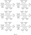
- FIG. 14 shows four consecutive reference signals in time domain, including Q1 to Q4. Different signals in the four reference signals are used as compensation signals and redundant signals.
- the compensation signal and the redundant signal have different relative time domain positions, which are used to carry corresponding data.
- a first time domain position is as follows: Q 1 and Q3 are compensation signals, and Q2 and Q4 are redundant signals.
- Q 1 and Q3 are compensation signals
- Q2 and Q4 are redundant signals.
- a second time domain position is as follows: Q1 and Q3 are redundant signals, and Q2 and Q4 are compensation signals.
- a third time domain position is as follows: Q1 and Q2 are compensation signals, and Q3 and Q4 are redundant signals.
- a fourth time domain position is as follows: Q1 and Q2 are redundant signals, and Q3 and Q4 are compensation signals.
- a fifth time domain position is as follows: Q1 and Q4 are redundant signals, and Q2 and Q3 are compensation signals.
- Q1 and Q4 are redundant signals
- Q2 and Q3 are compensation signals.
- a sixth time domain position is as follows: Q1 and Q4 are compensation signals, and Q2 and Q3 are redundant signals. Four of the six time domain positions may be used to carry data of two bits. In an example, the first time domain position indicates that a value of the two bits is 00, the second time domain position indicates that a value of the two bits is 01, the third time domain position indicates that a value of the two bits is 10, or the fourth time domain position indicates that a value of the two bits is 11. It may be understood that an example of using four signals as compensation signals and redundant signals is used above, which constitutes no limitation. If there are more compensation signals and redundant signals, data of more bits may be carried. On the contrary, if there are fewer compensation signals and redundant signals, data of fewer bits may be carried. For specific implementation, refer to the example. Details are not described again.
- Manner 12 The first data is carried in the first signal based on at least one of the following: the amplitude or the polarity of the first signal.
- the first signal includes a non-interference signal and an interference signal.
- the first data may be carried in the interference signal of the first signal (briefly referred to as an interference signal below) based on at least one of the following: an amplitude or a polarity of the interference signal. Additionally/Alternatively, the first data is carried in the non-interference signal of the first signal (briefly referred to as a non-interference signal below) based on at least one of the following: an amplitude or a polarity of the non-interference signal.
- the first data is carried in the interference signal based on at least one of the following: the amplitude or the polarity of the interference signal.
- the interference signal is also a real-imaginary separated signal.
- the interference signal may be an imaginary signal, which is a signal generated through interference by an imaginary part of another signal (for example, a data signal and a redundant signal), and is denoted as jINT.
- the interference signal may be a real signal, which is a signal generated through interference by a real part of another signal, and is denoted as INT.
- the first device may modulate a redundant signal, so that the amplitude and the polarity (positive or negative) of the interference signal, that is, jINT or INT, are one or more agreed fixed values.
- one or more fixed values of the amplitude of the interference signal may be used to carry data of one or more bits.
- Assumption 1 A real signal is used as an example (for understanding of an imaginary signal, refer to the example).
- An amplitude of the real signal has two fixed values, including 0.5 and 1, which may be used to carry data of one bit (bit).
- the fixed value 0.5 indicates that a value of the bit is 0, and the fixed value 1 indicates that a value of the bit is 1.
- the fixed value 0.5 indicates that a value of the bit is 1, and the fixed value 1 indicates that a value of the bit is 0.
- Assumption 2 A real signal is used as an example (for understanding of an imaginary signal, refer to the example).
- An amplitude of the real signal has four fixed values, including 0.25, 0.5, 0.75, and 1, which may be used to carry data of two bits.
- the fixed value 0.25 indicates that a value of the two bits is 00
- the fixed value 0.5 indicates that a value of the two bits is 01
- the fixed value 0.75 indicates that a value of the two bits is 10
- the fixed value 1 indicates that a value of the two bits is 11.
- Two polarities of the interference signal may be used to carry data of one bit.
- a real signal is used as an example (for understanding of an imaginary signal, refer to the example).
- a polarity of the real signal includes +INT or -INT.
- [+INT] indicates that a value of the bit is 1, and [-INT] indicates that a value of the bit is 0. Alternatively, [+INT] indicates that a value of the bit is 0, and [-INT] indicates that a value of the bit is 1.
- One or more fixed values of a combination of the amplitude and the polarity of the interference signal may be used to carry data of one or more bits.
- a combination of an amplitude and a polarity of the real signal has four fixed values, including -1, -0.5, 0.5, and 1, which may be used to carry data of two bits.
- the fixed value -1 indicates that a value of the two bits is 00
- the fixed value -0.5 indicates that a value of the two bits is 01
- the fixed value 0.5 indicates that a value of the two bits is 10
- the fixed value 1 indicates that a value of the two bits is 11.
- the amplitude of the interference signal has two fixed values or four fixed values is used above, which constitutes no limitation.
- the amplitude of the interference signal may have more fixed values, for example, eight fixed values or 16 fixed values, to carry data of more bits. For specific implementation, refer to the example. Details are not described again.
- the first data is carried in the first signal based on at least one of the following: the amplitude or the polarity of the non-interference signal.
- the non-interference signal is also a real-imaginary separated signal.
- the non-interference signal may be a real signal, denoted as Q i
- the non-interference signal may be an imaginary signal, denoted as jQ I .
- a polarity whether the real signal is a positive signal or a negative signal
- a polarity whether the imaginary signal is a positive signal or a negative signal
- ⁇ jQ I There are two signal types in total, which may be used to carry data of one bit.
- a real signal is used as an example (for understanding of an imaginary signal, refer to the example).
- [+Q i ] indicates that a value of the bit is 1
- [-Q i ] indicates that a value of the bit is 0.
- [+Q i ] indicates that a value of the bit is 0
- [-Q i ] indicates that a value of the bit is 1.
- a plurality of values of an amplitude of the real signal or a plurality of values of an amplitude of the imaginary signal may be used to carry data of one or more bits.
- Areal signal is used as an example (for understanding of an imaginary signal, refer to the example).
- An amplitude of the real signal has two values, including 0.5 and 1, which may be used to carry data of one bit.
- the value 0.5 indicates that a value of the bit is 0, and the value 1 indicates that a value of the bit is 1.
- the value 0.5 indicates that a value of the bit is 1, and the value 1 indicates that a value of the bit is 0.
- Assumption C A real signal is used as an example (for understanding of an imaginary signal, refer to the example).
- An amplitude of the real signal has four values, including 0.25, 0.5, 0.75, and 1, which may be used to carry data of two bits.
- the value 0.25 indicates that a value of the two bits is 00, the value 0.5 indicates that a value of the two bits is 01, the value 0.75 indicates that a value of the two bits is 10, or the value 1 indicates that a value of the two bits is 11.
- a plurality of values of a combination of an amplitude and a polarity of the real signal, or a plurality of values of a combination of an amplitude and a polarity of the imaginary signal may carry data of one or more bits.
- Assumption D A real signal is used as an example (for understanding of an imaginary signal, refer to the example).
- a combination of an amplitude and a polarity of the real signal has four values, including -1, -0.5, 0.5, and 1, which may be used to carry data of two bits.
- the value -1 indicates that a value of the two bits is 00
- the value -0.5 indicates that a value of the two bits is 01
- the value 0.5 indicates that a value of the two bits is 10
- the value 1 indicates that a value of the two bits is 11.
- non-interference signal and the interference signal may be combined, and Manner 11 and Manner 12 may also be combined, to jointly carry data of more bits, for example, jointly carry data corresponding to one or more of the following modulation orders: binary phase shift keying (binary phase shift keying, BPSK), pi/2-BPSK, quadrature phase shift keying (quadrature phase shift keying, QPSK), pi/4-QPSK, 8 phase shift keying (phase shift keying, PSK), 16PSK, 16 quadrature amplitude modulation (quadrature amplitude modulation, QAM), or 64QAM.
- binary phase shift keying binary phase shift keying
- BPSK binary phase shift keying
- QPSK quadrature phase shift keying
- pi/4-QPSK pi/4-QPSK
- 8 phase shift keying phase shift keying
- PSK phase shift keying
- 16PSK 16 quadrature amplitude modulation
- QAM quadrature amplitude modulation
- second data is carried in the second signal.
- the second signal is a data signal, and an interference signal of the second signal is random in magnitude, and therefore cannot be used to carry the second data.
- the second data may be carried in the second signal based on at least one of the following: an amplitude or a polarity of a non-interference signal of the second signal, that is, a signal of the second signal itself. Because the interference signal of the second signal cannot be used to carry data, the second signal mentioned below is the non-interference signal of the second signal, that is, the signal of the second signal itself.
- Manner 21 The second data is carried in the second signal based on a polarity of the second signal.
- the polarity of the second signal may be a polarity (whether the real signal is a positive signal or a negative signal) of the real signal, or a polarity (whether the imaginary signal is a positive signal or a negative signal) of the imaginary signal.
- Manner 22 The second data is carried in the second signal based on an amplitude of the second signal.
- the second signal is a real signal or an imaginary signal.
- An amplitude of the real signal or an amplitude of the imaginary signal may have a plurality of values, which are used to carry data of one or more bits.
- the real signal is used as an example.
- the amplitude of the real signal has four values, which are used to carry data of two bits; the amplitude of the real signal has eight values, which are used to carry data of three bits; the amplitude of the real signal has 16 values, which are used to carry data of four bits; or the amplitude of the real signal has 64 values, which are used to carry data of five bits; and so on. Details are not described again.
- Manner 21 and Manner 22 may be combined, to carry data of more bits.
- the first device may modulate a time-domain signal based on a parameter (denoted as a first MCS parameter) corresponding to an MCS of the first data, to include the first data in the time-domain signal and obtain a first time-domain signal.
- the first device performs OQAM on the first time-domain signal to obtain the first signal.
- the first device may further modulate a time-domain signal based on a parameter (denoted as a second MCS parameter) corresponding to an MCS of the second data, to include the second data in the time-domain signal and obtain a second time-domain signal.
- the first device performs OQAM on the second time-domain signal to obtain the second signal.
- OQAM refer to related descriptions in "5. OQAM”. Details are not described again.
- the first MCS parameter and the second MCS parameter refer to related descriptions in "S1303". Details are not described again.
- S1302 The first device sends the first signal and the second signal.
- the second device receives the first signal and the second signal.
- the first device may send the first signal and the second signal based on a radio frequency.
- the second device may receive the first signal and the second signal based on a radio frequency.
- the second device demodulates the first signal and the second signal.
- the second device may demodulate the first signal based on the first MCS parameter, to obtain the first data.
- the second device may demodulate the second signal based on the second MCS parameter, to obtain the second data.
- different signals in one scheduled bandwidth for example, the first signal and the second signal, are corresponding to different MCS parameters.
- the first MCS parameter is different from the second MCS parameter.
- the first MCS parameter may include at least one of the following: a modulation order, a code rate, or spectral efficiency.
- the modulation order of the first data may include one or more of the following: BPSK, pi/2-BPSK, QPSK, pi/4-QPSK, 8PSK, 16PSK, 16QAM, or 64QAM, so that the first device can select a modulation order suitable for a current service, to ensure stability and reliability of the service.
- the code rate of the first data may include one or more of the following: 517, 526, 553, 567, 602, 616, 658, 666, 682.5, 711, 719, 754, 772, 797, 822, 841, 885, 873, 910, 916.5, 948, or 1.
- the code rate of the first data is 1, it indicates that an original data bit is transmitted without being encoded, to further improve data transmission efficiency.
- the second MCS parameter may include at least one of the following: a modulation order, a code rate, or spectral efficiency. For a specific value, refer to related descriptions in "3. Reference signal density”. Details are not described again.
- the first MCS parameter may be indicated by information.
- the first device sends first information.
- the second device receives the first information.
- the first information indicates the first MCS parameter.
- the second MCS parameter may be indicated by information.
- the first device sends second information.
- the second device receives the second information.
- the second information indicates the second MCS parameter.
- the second device has an MCS configuration of the first MCS parameter.
- the MCS configuration may be scheduled by using signaling, for example, an RRC message, a DCI message, or a MAC-CE message.
- An example of the MCS configuration may be shown in Table 5.
- the first information may indicate a corresponding MCS index in Table 5.
- the second device may traverse Table 5 based on the first information, to determine the first MCS parameter.
- the first information may directly indicate the first MCS parameter, that is, at least one of the modulation order, the target code rate, or the frequency efficiency.
- the second device has an MCS configuration of the second MCS parameter.
- the MCS configuration may be scheduled by using signaling, for example, an RRC message, a DCI message, or a MAC-CE message.
- RRC message for example, an RRC message
- DCI message for example, a DCI message
- MAC-CE message for example, a MAC-CE message.
- the second information may indicate a corresponding MCS index in Table 1. In this way, the second device may traverse Table 1 based on the second information, to determine the second MCS parameter. Alternatively, the second information may directly indicate the second MCS parameter, that is, at least one of the modulation order, the target code rate, or the frequency efficiency.
- the first information may be carried in one or more of the following: an RRC message, a DCI message, or a MAC-CE message, to implement signaling reusing, reduce communication overheads, and improve communication efficiency.
- the first MCS parameter is scheduled by using the foregoing signaling.
- the second information may be carried in one or more of the following: an RRC message, a DCI message, or a MAC-CE message.
- the second MCS parameter is scheduled by using the foregoing signaling. In this way, signaling reusing can be implemented, communication overheads can be reduced, and communication efficiency can be improved.
- the foregoing messages may be different messages.
- the first information and the second information may be carried in different messages, and the first MCS parameter and the second MCS parameter are scheduled by using different signaling.
- a DCI message is used as an example.
- the first MCS parameter may be scheduled by using a first transport block field, for example, a field Modulation and/or coding scheme, in a first DCI message
- the second MCS parameter may be scheduled by using a first transport block field in a second DCI message.
- the foregoing messages may be a same message.
- the first information and the second information may be carried in one message, and the first MCS parameter and the second MCS parameter are scheduled by using same signaling.
- ADCI message is used as an example.
- the first MCS parameter may be scheduled by using a first transport block field carried in a DCI message, and the second information is scheduled by using a second transport block field carried in the DCI message.
- the second transport block field may be a newly added field, for example, at least one of the following fields: Modulation and/or coding scheme, New data indicator, or Redundancy version. It should be noted that at least some parameters of the first MCS parameter are different from those of the second MCS parameter, or all parameters of the first MCS parameter are different from those of the second MCS parameter. In other words, there are at least two MCS parameters in one scheduled bandwidth. For example, when the reference signal is used for phase noise compensation, the first MCS parameter may be less than the second MCS parameter, to ensure accuracy of phase noise compensation.
- At least some parameters of the first MCS parameter are different from those of the second MCS parameter.
- a same parameter of the first MCS parameter and the second MCS parameter may be scheduled by using a first transport block field, and a different parameter of the first MCS parameter and the second MCS parameter may be scheduled by using a second transport block field.
- the first MCS parameter is less than the second MCS parameter is merely an example.
- the first MCS parameter may alternatively be greater than or equal to the second MCS parameter.
- the first MCS parameter may be determined based on at least one of the following: the second MCS parameter, a parameter of the first data, a parameter of the first signal, or a parameter of the second signal.
- the first device may additionally indicate the parameter corresponding to the MCS of the first data, to reduce signaling overheads and improve communication efficiency.
- Manner 31 The first MCS parameter is determined based on the second MCS parameter.
- the first MCS parameter is related to the second MCS parameter, or there is a correspondence between the first MCS parameter and the second MCS parameter.
- the second device may determine the first MCS parameter based on the second MCS parameter and the one-to-one correspondence.
- the MCS parameter includes an MCS index, and the one-to-many relationship may be shown in Table 6.
- MCS index (MCS1) of second MCS parameter MCS index (MCS2) of first MCS parameter MCS1 ⁇ MCS11 No data carried in reference signal MCS 11 ⁇ MCS 1 ⁇ MCS 12 MCS2 ⁇ MCS21 MCS12 ⁇ MCS1 ⁇ MCS13 MCS2 ⁇ MCS22 ... ... MCS1n ⁇ MCS1 ⁇ MCS1n MCS2 ⁇ MCS2(n-1) MCS1n ⁇ MCS1 MCS2 ⁇ MCS2n
- MCS1 when the MCS index (namely, MCS1) of the second MCS parameter is greater than or equal to MCS11, a plurality of MCS indexes (namely, MCS2) of the first MCS parameter are corresponding to MCS 1.
- MCS11 when MCS11 ⁇ MCS1 ⁇ MCS12, a value range of MCS2 corresponding to MCS1 is as follows: MCS2 ⁇ MCS21. In other words, there may be a plurality of MCS2s.
- the second device After determining the second MCS parameter, for example, after determining the second MCS parameter based on the second information, the second device may determine a plurality of first MCS parameters based on the second MCS parameter and the one-to-many relationship.
- the second device may determine a to-be-used first MCS parameter from the plurality of first MCS parameters based on indication information from a higher layer of a network, for example, a core network element.
- the correspondence between the first MCS parameter and the second MCS parameter may be configured by using signaling, for example, an RRC message, a MAC-CE message, or a DCI message.
- signaling for example, an RRC message, a MAC-CE message, or a DCI message.
- all correspondences between the first MCS parameter and the second MCS parameter are configured by using RRC signaling (or MAC-CE signaling).
- RRC signaling or MAC-CE signaling
- a part of the correspondence between the first MCS parameter and the second MCS parameter is configured by using RRC signaling (or MAC-CE signaling)
- another part of the correspondence between the first MCS parameter and the second MCS parameter is configured by using DCI. It may be understood that the correspondence between the first MCS parameter and the second MCS parameter configured by using signaling is merely an example, which constitutes no limitation.
- the first MCS parameter when the first MCS parameter is less than the second MCS parameter, the first MCS parameter may be further configured, by using signaling, to be K MCS levels less than the second MCS parameter, or the second MCS parameter may be configured, by using signaling, to be K MCS levels greater than the first MCS parameter, where K is a positive integer.
- K may be configured, by using signaling, to be equal to 2. In this way, after determining that the MCS index of the second MCS parameter is 7, the second device may determine that the MCS index of the first MCS parameter is 5 because the MCS index of the second MCS parameter is 7 and K is equal to 2.
- the MCS parameter includes the MCS index
- the MCS index may be replaced with a target code rate, a modulation order, or spectral efficiency.
- the MCS index in Table 6 is replaced with a modulation order
- the second MCS parameter is 16QAM
- the first MCS parameter is QPSK.
- the second MCS parameter is 64QAM
- the first MCS parameter is 16QAM or 8PSK.
- the first MCS parameter is determined based on the second MCS parameter
- the second MCS parameter may be determined based on the first MCS parameter, and a specific implementation principle is similar to that the first MCS parameter is determined based on the second MCS parameter.
- the first MCS parameter is determined based on at least one of the following: a parameter of the first data, a parameter of the first signal, or a parameter of the second signal.
- the parameter of the first data may be a quantity of bits of the first data.
- the parameter of the first signal may include one or more of the following: a frequency domain density of the first signal, a time domain density of the first signal, a power of the first signal, a quantity of first signals, or a quantity of first signal blocks, where the first signal block includes the first signal, to ensure that the second device can accurately determine the parameter corresponding to the MCS of the first data.
- the parameter of the second signal may include one or more of the following: a quantity of resources corresponding to the second signal or a power of the second signal, to ensure that the second device can accurately determine the parameter corresponding to the MCS of the first data.
- the frequency domain density of the first signal the time domain density of the first signal, the quantity of first signals, and the quantity of first signal blocks, refer to related descriptions in "3. Reference signal density". Details are not described again.
- the power of the first signal may be twice a power of an outermost constellation point of the second signal.
- the first signal and the second signal may have a same MCS, for example, the first MCS parameter is the same as the second MSC parameter.
- the quantity of resources corresponding to the second signal may indicate a bandwidth, for example, a bandwidth scheduled by using a DCI message.
- the quantity of resources corresponding to the second signal may indicate a length of duration, for example, one or more slots, or one or more symbols.
- the first MCS parameter includes spectral efficiency of the first data.
- Spectral efficiency of the first signal may be determined based on the quantity of first signals and a modulation order of the first signal.
- the quantity of first signals may be determined based on the following: the quantity of resources corresponding to the second signal, the quantity of bits of the first data, and the frequency domain density of the first signal.
- the bandwidth indicated by the quantity of resources corresponding to the second data is 60 RBs, and there is an RE carrying one first signal on every two RBs (that is, the frequency domain density of the first signal is 2).
- the quantity of resources corresponding to the second signal indicates one slot (one slot includes 14 symbols).
- the first data when the quantity of first signals is less than a first threshold, or the quantity of bits of the first data is less than a second threshold, the first data may be transmitted by using a sequence, that is, the first data is not encoded. Each first signal sequence may indicate one piece of first data.
- the first data when the quantity of first signals is greater than or equal to the first threshold, or the quantity of bits of the first data is greater than or equal to the second threshold, the first data may be transmitted at a high code rate. In this case, because the quantity of bits of the first data is large, transmission at a high code rate brings a high coding gain.
- the first MCS parameter may be increased when the power of the first signal is increased.
- the first MCS parameter may be increased by N times.
- the first MCS parameter includes an MCS index of the first data, and M is equal to 2 and N is equal to 3, when the power of the first signal is increased by two times, the MCS index of the first data may be increased by three levels.
- One MCS index may be understood as one level.
- MCS11, MCS12, MCS13, ..., and MCS1n each are one level, and MCS11 is one level lower than MCS12.
- Values of M and N may be configured by using RRC signaling (or MAC-CE signaling), or may be agreed in a protocol. This is not limited in embodiments of this application.
- the parameter corresponding to the MCS of the first data is different from the parameter corresponding to the MCS of the second data, indicating that one of the first signal and the second signal is a reference signal and the other is a data signal, so that data is transmitted based on the reference signal, and data transmission efficiency and spectral efficiency are improved.
- the communication method according to embodiments of this application is described in detail with reference to FIG. 13 and FIG. 14 .
- a communication apparatus configured to perform the communication method according to embodiments of this application is described below in detail with reference to FIG. 15 to FIG. 8 .
- FIG. 15 is a schematic diagram 1 of a structure of a communication apparatus according to an embodiment of this application.
- the communication apparatus 1500 includes a transceiver module 1501 and a processing module 1502.
- FIG. 15 shows only main components of the communication apparatus.
- the communication apparatus 1500 is applicable to the communication system shown in FIG. 12 , and performs a function of the first device in the method shown in FIG. 13 .
- the processing module 1502 is configured to obtain a first signal and a second signal based on OQAM.
- the transceiver module 1501 is configured to send the first signal and the second signal.
- First data is carried in the first signal
- second data is carried in the second signal
- a parameter corresponding to an MCS of the first data is different from a parameter corresponding to an MCS of the second data.
- the first data is carried in the first signal based on a time domain position of the first signal.
- the first data may alternatively be carried in the first signal based on at least one of the following: a polarity or an amplitude of the first signal.
- the parameter corresponding to the MCS of the first data may be determined based on at least one of the following: a parameter of the first data, a parameter of the first signal, a parameter of the second signal, or the parameter corresponding to the MCS of the second data.
- the parameter corresponding to the MCS of the first data may be less than the parameter corresponding to the MCS of the second data.
- the parameter of the first signal may include one or more of the following: a frequency domain density of the first signal, a time domain density of the first signal, a power of the first signal, a quantity of first signals, or a quantity of first signal blocks, where the first signal block includes the first signal.
- the parameter of the second signal may include one or more of the following: a quantity of resources corresponding to the second signal or a power of the second signal.
- the parameter corresponding to the MCS of the first data includes at least one of the following: a modulation order, a code rate, or spectral efficiency.
- the modulation order may include one or more of the following: BPSK, QPSK, 8PSK, or 16QAM.
- the code rate may include 1.
- the transceiver module 1501 is further configured to send first information, and the first information indicates the parameter corresponding to the MCS of the first data.
- the first information is carried in one or more of the following: an RRC message, a DCI message, or a MAC-CE message.
- the transceiver module 1501 may further include a sending module and a receiving module (not shown in FIG. 15 ).
- the sending module is configured to implement a sending function of the communication apparatus 1500
- the receiving module is configured to implement a receiving function of the communication apparatus 1500.
- the communication apparatus 1500 may further include a storage module (not shown in FIG. 15 ), and the storage module stores a program or instructions.
- the processing module executes the program or the instructions, the communication apparatus 1500 is enabled to perform a function of the first device in the method shown in FIG. 13 .
- the processing module in the communication apparatus 1500 may be implemented by a processor or a processor-related circuit component, and may be a processor or a processing unit.
- the transceiver module may be implemented by a transceiver or a transceiver-related circuit component, and may be a transceiver or a transceiver unit.
- the communication apparatus 1500 may be a terminal or a network device, may be a chip (system) or another part or component that can be disposed in a terminal or a network device, or may be an apparatus that includes a terminal or a network device. This is not limited in this application.
- the communication apparatus 1500 is applicable to the communication system shown in FIG. 12 , and performs a function of the second device in the method shown in FIG. 13 .
- the transceiver module 1501 is configured to receive a first signal and a second signal.
- the processing module 1502 is configured to demodulate the first signal and the second signal.
- the first signal and the second signal are signals obtained based on OQAM, first data is carried in the first signal, second data is carried in the second signal, and a parameter corresponding to an MCS of the first data is different from a parameter corresponding to an MCS of the second data.
- the first data is carried in the first signal based on a time domain position of the first signal.
- the first data may alternatively be carried in the first signal based on at least one of the following: a polarity or an amplitude of the first signal.
- the parameter corresponding to the MCS of the first data may be determined based on at least one of the following: a parameter of the first data, a parameter of the first signal, a parameter of the second signal, or the parameter corresponding to the MCS of the second data.
- the parameter corresponding to the MCS of the first data may be less than the parameter corresponding to the MCS of the second data.
- the parameter of the first signal may include one or more of the following: a frequency domain density of the first signal, a time domain density of the first signal, a power of the first signal, a quantity of first signals, or a quantity of first signal blocks, where the first signal block includes the first signal.
- the parameter of the second signal may include one or more of the following: a quantity of resources corresponding to the second signal or a power of the second signal.
- the parameter corresponding to the MCS of the first data includes at least one of the following: a modulation order, a code rate, or spectral efficiency.
- the modulation order may include one or more of the following: BPSK, QPSK, 8PSK, or 16QAM.
- the code rate may include 1.
- the transceiver module 1501 is further configured to receive first information, and the first information indicates the parameter corresponding to the MCS of the first data.
- the first information is carried in one or more of the following: an RRC message, a DCI message, or a MAC-CE message.
- the transceiver module 1501 may further include a sending module and a receiving module (not shown in FIG. 15 ).
- the sending module is configured to implement a sending function of the communication apparatus 1500
- the receiving module is configured to implement a receiving function of the communication apparatus 1500.
- the communication apparatus 1500 may further include a storage module (not shown in FIG. 15 ), and the storage module stores a program or instructions.
- the processing module executes the program or the instructions, the communication apparatus 1500 is enabled to perform a function of the second device in the method shown in FIG. 13 .
- the processing module in the communication apparatus 1500 may be implemented by a processor or a processor-related circuit component, and may be a processor or a processing unit.
- the transceiver module may be implemented by a transceiver or a transceiver-related circuit component, and may be a transceiver or a transceiver unit.
- the communication apparatus 1500 may be a terminal or a network device, may be a chip (system) or another part or component that can be disposed in a terminal or a network device, or may be an apparatus that includes a terminal or a network device. This is not limited in this application.
- FIG. 16 is a schematic diagram 2 of a structure of a communication apparatus according to an embodiment of this application.
- the communication apparatus may be a terminal device or a network device, or may be a chip (system) or another part or component that can be disposed in a terminal device or a network device.
- the communication apparatus 1600 may include a processor 1601.
- the communication apparatus 1600 may further include a memory 1602 and/or a transceiver 1603.
- the processor 1601 is coupled to the memory 1602 and the transceiver 1603, for example, may be connected to the memory 1602 and the transceiver 1603 through a communication bus.
- the processor 1601 is a control center of the communication apparatus 1600, and may be a processor, may be a collective name of a plurality of processing elements, or may be referred to as a logic circuit.
- the processor 1601 may be one or more central processing units (central processing units, CPUs), or may be an application-specific integrated circuit (application-specific integrated circuit, ASIC), or one or more integrated circuits configured to implement embodiments of this application, for example, one or more microprocessors (digital signal processors, DSPs) or one or more field programmable gate arrays (field programmable gate arrays, FPGAs).
- the processor 1601 may perform various functions of the communication apparatus 1600 by running or executing a software program stored in the memory 1602 and invoking data stored in the memory 1602.
- the processor 1601 may include one or more CPUs, for example, a CPU 0 and a CPU 1 shown in FIG. 16 .
- the communication apparatus 1600 may alternatively include a plurality of processors, for example, the processor 1601 and a processor 1604 shown in FIG. 1 .
- Each of the processors may be a single-CPU (single-CPU) processor or may be a multi-CPU (multi-CPU) processor.
- the processor herein may be one or more devices, circuits, and/or processing cores configured to process data (for example, computer program instructions).
- the memory 1602 is configured to store a software program for performing the solutions of this application, and is controlled by the processor 1601, so that the method shown in FIG. 13 is performed.
- the memory 1602 may be a read-only memory (read-only memory, ROM) or another type of static storage device that can store static information and instructions, or a random access memory (random access memory, RAM) or another type of dynamic storage device that can store information and instructions, or may be an electrically erasable programmable read-only memory (electrically erasable programmable read-only memory, EEPROM), a compact disc read-only memory (compact disc read-only memory, CD-ROM) or another compact disc storage, an optical disc storage (including a compact disc, a laser disc, an optical disc, a digital versatile disc, a Blu-ray disc, or the like), a magnetic disk storage medium or another magnetic storage device, or any other medium that can be used to carry or store expected program code in a form of instruction or data structure and that can be accessed by a computer.
- ROM read-only memory
- RAM random access memory
- EEPROM electrically erasable programmable read-only memory
- CD-ROM compact disc read-only memory
- the memory 1602 may be integrated with the processor 1601, or may exist independently, and is coupled to the processor 1601 through an interface circuit or an input/output interface (not shown in FIG. 16 ) of the communication apparatus 1600. This is not specifically limited in embodiments of this application.
- the transceiver 1603 is configured to communicate with another communication apparatus.
- the communication apparatus 1600 is a terminal, and the transceiver 1603 may be configured to communicate with a network device or communicate with another terminal device.
- the communication apparatus 1600 is a network device, and the transceiver 1603 may be configured to communicate with a terminal or communicate with another network device.
- the transceiver 1603 may include a receiver and a transmitter (not separately shown in FIG. 16 ).
- the receiver is configured to implement a receiving function
- the transmitter is configured to implement a sending function.
- the transceiver 1603 may be integrated with the processor 1601, or may exist independently, and is coupled to the processor 1601 through an interface circuit (not shown in FIG. 16 ) of the communication apparatus 1600. This is not specifically limited in embodiments of this application.
- the structure of the communication apparatus 1600 shown in FIG. 16 does not constitute a limitation on the communication apparatus.
- An actual communication apparatus may include more or fewer components than those shown in the figure, combine some components, or have different component arrangements.
- FIG. 17 is a schematic diagram 3 of a structure of a communication apparatus according to an embodiment of this application.
- the communication apparatus may be a terminal device or a network device, or may be a chip (system) or another part or component that can be disposed in a terminal device or a network device.
- the communication apparatus 1700 may include a logic circuit 1701 and an input/output interface 1702.
- the input/output interface 1702 is configured to receive code instructions and transmit the code instructions to the logic circuit 1701.
- the logic circuit 1701 is configured to run the code instructions to perform the foregoing method.
- An embodiment of this application provides a communication system.
- the communication system includes one or more terminals and one or more network devices described above.
- the processor may be a CPU, or the processor may be another general-purpose processor, a DSP, an ASIC, a field programmable gate array FPGA or another programmable logic device, a discrete gate or a transistor logic device, a discrete hardware component, or the like.
- the general-purpose processor may be a microprocessor, or the processor may be any conventional processor, or the like.
- the memory may be a volatile memory or a nonvolatile memory, or may include both a volatile memory and a nonvolatile memory.
- the nonvolatile memory may be a ROM, a programmable read-only memory (programmable ROM, PROM), an erasable programmable read-only memory (erasable PROM, EPROM), an EEPROM, or a flash memory.
- the volatile memory may be a RAM, and serves as an external cache.
- RAMs may be used, for example, a static random access memory (static RAM, SRAM), a dynamic random access memory (DRAM), a synchronous dynamic random access memory (synchronous DRAM, SDRAM), a double data rate synchronous dynamic random access memory (double data rate SDRAM, DDR SDRAM), an enhanced synchronous dynamic random access memory (enhanced SDRAM, ESDRAM), a synchlink dynamic random access memory (synchlink DRAM, SLDRAM), and a direct rambus random access memory (direct rambus RAM, DR RAM).
- static random access memory static random access memory
- DRAM dynamic random access memory
- SDRAM synchronous dynamic random access memory
- double data rate SDRAM double data rate SDRAM
- DDR SDRAM double data rate SDRAM
- ESDRAM enhanced synchronous dynamic random access memory
- synchlink dynamic random access memory synchlink dynamic random access memory
- SLDRAM direct rambus random access memory
- direct rambus RAM direct rambus RAM
- All or some of the foregoing embodiments may be implemented by using software, hardware (for example, a circuit), firmware, or any combination thereof.
- software is used to implement embodiments, all or some of the foregoing embodiments may be implemented in a form of computer program product.
- the computer program product includes one or more computer instructions or computer programs. When the computer instructions or the computer programs or instructions are loaded or executed on a computer, all or some of the procedures or functions according to embodiments of this application are generated.
- the computer may be a general-purpose computer, a dedicated computer, a computer network, or another programmable apparatus.
- the computer instructions may be stored in a computer-readable storage medium or may be transmitted from a computer-readable storage medium to another computer-readable storage medium.
- the computer instructions may be transmitted from a website, computer, server, or data center to another website, computer, server, or data center in a wired (for example, infrared, radio, or microwave) manner.
- the computer-readable storage medium may be any usable medium that can be accessed by a computer, or a data storage device, for example, a server or a data center integrating one or more usable media.
- the usable medium may be a magnetic medium (for example, a floppy disk, a hard disk, or a magnetic tape), an optical medium (for example, a DVD), or a semiconductor medium.
- the semiconductor medium may be a solid-state drive.
- At least one means one or more, and "a plurality of” means two or more.
- At least one of the following items (pieces)" or a similar expression thereof means any combination of these items, including any combination of singular or plural items (pieces).
- at least one of a, b, or c may indicate: a, b, c, a and b, a and c, b and c, or a, b, and c, where a, b, and c may be singular or plural.
- sequence numbers of the foregoing processes do not mean execution sequences.
- the execution sequences of the processes should be determined based on functions and internal logic of the processes, and shall not constitute any limitation on implementation processes of embodiments of this application.
- the disclosed system, apparatus, and method may be implemented in other manners.
- the described apparatus embodiments are merely examples.
- division into the units is merely logical function division and may be other division during actual implementation.
- a plurality of units or components may be combined or integrated into another system, or some features may be ignored or may not be performed.
- the displayed or discussed mutual couplings or direct couplings or communication connections may be implemented by using some interfaces.
- the indirect couplings or communication connections between apparatuses or units may be implemented in electrical, mechanical, or other forms.
- Units described as separate parts may or may not be physically separate, and parts displayed as units may or may not be physical units, may be located in one position, or may be distributed on a plurality of network units. Some or all of the units may be selected according to an actual requirement to achieve objectives of the solutions of embodiments.
- the functions When the functions are implemented in a form of software functional unit and sold or used as an independent product, the functions may be stored in a computer-readable storage medium. Based on such an understanding, the technical solutions of this application essentially or a part contributing to a conventional technology or some of the technical solutions may be implemented in a form of software product.
- the computer software product is stored in a storage medium, and includes several instructions for instructing a computer device (which may be a personal computer, a server, a network device, or the like) to perform all or some of the steps of the method described in embodiments of this application.
- the foregoing storage medium includes any medium that can store program code, such as a USB flash drive, a removable hard disk, a ROM, a RAM, a magnetic disk, or an optical disc.
Landscapes
- Engineering & Computer Science (AREA)
- Computer Networks & Wireless Communication (AREA)
- Signal Processing (AREA)
- Quality & Reliability (AREA)
- Physics & Mathematics (AREA)
- Discrete Mathematics (AREA)
- General Physics & Mathematics (AREA)
- Mathematical Physics (AREA)
- Power Engineering (AREA)
- Mobile Radio Communication Systems (AREA)
Applications Claiming Priority (2)
| Application Number | Priority Date | Filing Date | Title |
|---|---|---|---|
| CN202111567396.4A CN116319197A (zh) | 2021-12-20 | 2021-12-20 | 通信方法及装置 |
| PCT/CN2022/139956 WO2023116613A1 (zh) | 2021-12-20 | 2022-12-19 | 通信方法及装置 |
Publications (2)
| Publication Number | Publication Date |
|---|---|
| EP4436083A1 true EP4436083A1 (de) | 2024-09-25 |
| EP4436083A4 EP4436083A4 (de) | 2025-03-26 |
Family
ID=86789267
Family Applications (1)
| Application Number | Title | Priority Date | Filing Date |
|---|---|---|---|
| EP22909926.2A Pending EP4436083A4 (de) | 2021-12-20 | 2022-12-19 | Kommunikationsverfahren und -vorrichtung |
Country Status (3)
| Country | Link |
|---|---|
| EP (1) | EP4436083A4 (de) |
| CN (1) | CN116319197A (de) |
| WO (1) | WO2023116613A1 (de) |
Cited By (1)
| Publication number | Priority date | Publication date | Assignee | Title |
|---|---|---|---|---|
| WO2025166098A1 (en) * | 2024-02-02 | 2025-08-07 | Interdigital Patent Holdings, Inc. | Methods and apparatuses for constellation shaping for single-carrier waveform with selection of an mcs table |
Families Citing this family (5)
| Publication number | Priority date | Publication date | Assignee | Title |
|---|---|---|---|---|
| CN121128113A (zh) * | 2023-07-29 | 2025-12-12 | 华为技术有限公司 | 通信方法及装置 |
| WO2025054780A1 (zh) * | 2023-09-11 | 2025-03-20 | 华为技术有限公司 | 通信方法及装置 |
| CN120342816A (zh) * | 2024-01-18 | 2025-07-18 | 华为技术有限公司 | 一种通信方法以及通信装置 |
| CN120166553A (zh) * | 2024-04-03 | 2025-06-17 | 中兴通讯股份有限公司 | 信号传输方法、装置、存储介质及程序产品 |
| CN121865393A (zh) * | 2024-10-11 | 2026-04-14 | 华为技术有限公司 | 通信方法及通信装置 |
Family Cites Families (5)
| Publication number | Priority date | Publication date | Assignee | Title |
|---|---|---|---|---|
| CN113938366B (zh) * | 2017-03-08 | 2024-05-10 | 松下电器(美国)知识产权公司 | 发送装置、发送方法、接收装置及接收方法 |
| WO2020138983A1 (ko) * | 2018-12-27 | 2020-07-02 | 엘지전자 주식회사 | 무선 통신 시스템에서 단말 및 기지국의 동작 방법 및 이를 지원하는 장치 |
| WO2021189216A1 (zh) * | 2020-03-23 | 2021-09-30 | 华为技术有限公司 | 参考信号设置方法及装置 |
| US11632210B2 (en) * | 2020-05-08 | 2023-04-18 | Qualcomm Incorporated | Enhanced phase tracking reference signal |
| US12244528B2 (en) * | 2020-05-19 | 2025-03-04 | Qualcomm Incorporated | Amplitude modulated phase tracking reference signals |
-
2021
- 2021-12-20 CN CN202111567396.4A patent/CN116319197A/zh active Pending
-
2022
- 2022-12-19 EP EP22909926.2A patent/EP4436083A4/de active Pending
- 2022-12-19 WO PCT/CN2022/139956 patent/WO2023116613A1/zh not_active Ceased
Cited By (1)
| Publication number | Priority date | Publication date | Assignee | Title |
|---|---|---|---|---|
| WO2025166098A1 (en) * | 2024-02-02 | 2025-08-07 | Interdigital Patent Holdings, Inc. | Methods and apparatuses for constellation shaping for single-carrier waveform with selection of an mcs table |
Also Published As
| Publication number | Publication date |
|---|---|
| WO2023116613A1 (zh) | 2023-06-29 |
| CN116319197A (zh) | 2023-06-23 |
| EP4436083A4 (de) | 2025-03-26 |
Similar Documents
| Publication | Publication Date | Title |
|---|---|---|
| EP4436083A1 (de) | Kommunikationsverfahren und -vorrichtung | |
| CN109428846B (zh) | 一种信号传输的方法、设备及系统 | |
| US12137016B2 (en) | Data modulation method and apparatus, device, and storage medium | |
| US11546193B2 (en) | Data compression method and apparatus | |
| EP4407941A1 (de) | Kommunikationsverfahren und -vorrichtung | |
| CN115516826B (zh) | 峰均功率比降低 | |
| EP4120645A1 (de) | Ofdm-basiertes verfahren und vorrichtung zum spreizen und senden komprimierter daten | |
| US20230308334A1 (en) | Signal transmission method and apparatus | |
| EP4387178A1 (de) | Signalübertragungsverfahren und -vorrichtung | |
| US20240414041A1 (en) | Signal transmission method and communication apparatus | |
| US12483447B2 (en) | Phase noise estimation method, apparatus, and system | |
| EP4037275B1 (de) | Verfahren und vorrichtung zum senden von daten in einem drahtlosen kommunikationssystem | |
| CN109983742B (zh) | 在无线通信系统中发送和接收信号的装置和方法 | |
| EP4030655B1 (de) | Verfahren und vorrichtung zur verarbeitung eines signals in einem drahtloskommunikationssystem | |
| WO2023246422A1 (zh) | 数据处理方法和数据处理装置 | |
| EP4373043A1 (de) | Signalübertragungsverfahren und -vorrichtung | |
| CN115913853A (zh) | 一种相位跟踪参考信号的传输方法及装置 | |
| US20260019311A1 (en) | Communication method and apparatus | |
| EP4521693A1 (de) | Datenmodulationsverfahren und -vorrichtung sowie medium und speichermedium | |
| EP4429331A1 (de) | Kommunikationsverfahren und -vorrichtung | |
| EP4734403A1 (de) | Kommunikationsverfahren und -vorrichtung | |
| WO2024196369A1 (en) | Apparatus and method for interference port detection in a multiple user multiple input multiple output scenario | |
| WO2025152689A1 (zh) | 一种通信方法以及通信装置 | |
| WO2025060106A1 (zh) | 一种通信方法及通信装置 | |
| WO2026026791A1 (zh) | 处理信号的方法和装置 |
Legal Events
| Date | Code | Title | Description |
|---|---|---|---|
| STAA | Information on the status of an ep patent application or granted ep patent |
Free format text: STATUS: THE INTERNATIONAL PUBLICATION HAS BEEN MADE |
|
| PUAI | Public reference made under article 153(3) epc to a published international application that has entered the european phase |
Free format text: ORIGINAL CODE: 0009012 |
|
| STAA | Information on the status of an ep patent application or granted ep patent |
Free format text: STATUS: REQUEST FOR EXAMINATION WAS MADE |
|
| 17P | Request for examination filed |
Effective date: 20240620 |
|
| AK | Designated contracting states |
Kind code of ref document: A1 Designated state(s): AL AT BE BG CH CY CZ DE DK EE ES FI FR GB GR HR HU IE IS IT LI LT LU LV MC ME MK MT NL NO PL PT RO RS SE SI SK SM TR |
|
| A4 | Supplementary search report drawn up and despatched |
Effective date: 20250224 |
|
| DAV | Request for validation of the european patent (deleted) | ||
| DAX | Request for extension of the european patent (deleted) | ||
| RIC1 | Information provided on ipc code assigned before grant |
Ipc: H04L 27/20 20060101ALI20250219BHEP Ipc: H04L 27/26 20060101ALI20250219BHEP Ipc: H04L 27/34 20060101ALI20250219BHEP Ipc: H04L 1/00 20060101ALI20250219BHEP Ipc: H04L 5/00 20060101AFI20250219BHEP |