EP4429331A1 - Kommunikationsverfahren und -vorrichtung - Google Patents
Kommunikationsverfahren und -vorrichtung Download PDFInfo
- Publication number
- EP4429331A1 EP4429331A1 EP22903410.3A EP22903410A EP4429331A1 EP 4429331 A1 EP4429331 A1 EP 4429331A1 EP 22903410 A EP22903410 A EP 22903410A EP 4429331 A1 EP4429331 A1 EP 4429331A1
- Authority
- EP
- European Patent Office
- Prior art keywords
- signal
- reference frequency
- frequency
- sequence
- synchronization
- Prior art date
- Legal status (The legal status is an assumption and is not a legal conclusion. Google has not performed a legal analysis and makes no representation as to the accuracy of the status listed.)
- Pending
Links
- 238000000034 method Methods 0.000 title claims abstract description 132
- 238000004891 communication Methods 0.000 title claims abstract description 113
- 238000004590 computer program Methods 0.000 claims description 18
- 238000005516 engineering process Methods 0.000 abstract description 3
- 238000013473 artificial intelligence Methods 0.000 abstract 1
- 238000005070 sampling Methods 0.000 description 61
- 238000012545 processing Methods 0.000 description 30
- 238000006243 chemical reaction Methods 0.000 description 29
- 238000013461 design Methods 0.000 description 29
- 230000006870 function Effects 0.000 description 29
- 230000008569 process Effects 0.000 description 29
- 238000010586 diagram Methods 0.000 description 24
- 230000000694 effects Effects 0.000 description 23
- 238000005562 fading Methods 0.000 description 18
- 230000005540 biological transmission Effects 0.000 description 6
- 238000010295 mobile communication Methods 0.000 description 6
- 230000003287 optical effect Effects 0.000 description 5
- 230000010363 phase shift Effects 0.000 description 5
- 230000001360 synchronised effect Effects 0.000 description 5
- 230000003068 static effect Effects 0.000 description 4
- 108010076504 Protein Sorting Signals Proteins 0.000 description 3
- 238000012937 correction Methods 0.000 description 3
- 230000008878 coupling Effects 0.000 description 3
- 238000010168 coupling process Methods 0.000 description 3
- 238000005859 coupling reaction Methods 0.000 description 3
- 125000004122 cyclic group Chemical group 0.000 description 3
- 230000011664 signaling Effects 0.000 description 3
- 241001673391 Entandrophragma candollei Species 0.000 description 2
- 238000003491 array Methods 0.000 description 2
- 230000003190 augmentative effect Effects 0.000 description 2
- 230000001413 cellular effect Effects 0.000 description 2
- 230000007774 longterm Effects 0.000 description 2
- 238000005259 measurement Methods 0.000 description 2
- 230000004044 response Effects 0.000 description 2
- 239000004065 semiconductor Substances 0.000 description 2
- 230000003595 spectral effect Effects 0.000 description 2
- 238000004458 analytical method Methods 0.000 description 1
- 239000013256 coordination polymer Substances 0.000 description 1
- 238000013500 data storage Methods 0.000 description 1
- 230000004069 differentiation Effects 0.000 description 1
- 230000008030 elimination Effects 0.000 description 1
- 238000003379 elimination reaction Methods 0.000 description 1
- 238000001914 filtration Methods 0.000 description 1
- PCHJSUWPFVWCPO-UHFFFAOYSA-N gold Chemical group [Au] PCHJSUWPFVWCPO-UHFFFAOYSA-N 0.000 description 1
- 239000007787 solid Substances 0.000 description 1
- 230000001960 triggered effect Effects 0.000 description 1
Images


Classifications
-
- H—ELECTRICITY
- H04—ELECTRIC COMMUNICATION TECHNIQUE
- H04W—WIRELESS COMMUNICATION NETWORKS
- H04W52/00—Power management, e.g. Transmission Power Control [TPC] or power classes
- H04W52/02—Power saving arrangements
- H04W52/0209—Power saving arrangements in terminal devices
- H04W52/0212—Power saving arrangements in terminal devices managed by the network, e.g. network or access point is leader and terminal is follower
- H04W52/0216—Power saving arrangements in terminal devices managed by the network, e.g. network or access point is leader and terminal is follower using a pre-established activity schedule, e.g. traffic indication frame
-
- H—ELECTRICITY
- H04—ELECTRIC COMMUNICATION TECHNIQUE
- H04W—WIRELESS COMMUNICATION NETWORKS
- H04W52/00—Power management, e.g. Transmission Power Control [TPC] or power classes
- H04W52/02—Power saving arrangements
-
- H—ELECTRICITY
- H04—ELECTRIC COMMUNICATION TECHNIQUE
- H04L—TRANSMISSION OF DIGITAL INFORMATION, e.g. TELEGRAPHIC COMMUNICATION
- H04L27/00—Modulated-carrier systems
- H04L27/0014—Carrier regulation
-
- H—ELECTRICITY
- H04—ELECTRIC COMMUNICATION TECHNIQUE
- H04L—TRANSMISSION OF DIGITAL INFORMATION, e.g. TELEGRAPHIC COMMUNICATION
- H04L27/00—Modulated-carrier systems
- H04L27/26—Systems using multi-frequency codes
- H04L27/2601—Multicarrier modulation systems
- H04L27/2602—Signal structure
- H04L27/261—Details of reference signals
- H04L27/2613—Structure of the reference signals
-
- H—ELECTRICITY
- H04—ELECTRIC COMMUNICATION TECHNIQUE
- H04L—TRANSMISSION OF DIGITAL INFORMATION, e.g. TELEGRAPHIC COMMUNICATION
- H04L27/00—Modulated-carrier systems
- H04L27/26—Systems using multi-frequency codes
- H04L27/2601—Multicarrier modulation systems
- H04L27/2647—Arrangements specific to the receiver only
- H04L27/2655—Synchronisation arrangements
-
- H—ELECTRICITY
- H04—ELECTRIC COMMUNICATION TECHNIQUE
- H04L—TRANSMISSION OF DIGITAL INFORMATION, e.g. TELEGRAPHIC COMMUNICATION
- H04L5/00—Arrangements affording multiple use of the transmission path
- H04L5/0001—Arrangements for dividing the transmission path
- H04L5/0003—Two-dimensional division
- H04L5/0005—Time-frequency
- H04L5/0007—Time-frequency the frequencies being orthogonal, e.g. OFDM(A) or DMT
- H04L5/001—Time-frequency the frequencies being orthogonal, e.g. OFDM(A) or DMT the frequencies being arranged in component carriers
-
- H—ELECTRICITY
- H04—ELECTRIC COMMUNICATION TECHNIQUE
- H04L—TRANSMISSION OF DIGITAL INFORMATION, e.g. TELEGRAPHIC COMMUNICATION
- H04L5/00—Arrangements affording multiple use of the transmission path
- H04L5/003—Arrangements for allocating sub-channels of the transmission path
- H04L5/0048—Allocation of pilot signals, i.e. of signals known to the receiver
- H04L5/0051—Allocation of pilot signals, i.e. of signals known to the receiver of dedicated pilots, i.e. pilots destined for a single user or terminal
-
- H—ELECTRICITY
- H04—ELECTRIC COMMUNICATION TECHNIQUE
- H04W—WIRELESS COMMUNICATION NETWORKS
- H04W52/00—Power management, e.g. Transmission Power Control [TPC] or power classes
- H04W52/02—Power saving arrangements
- H04W52/0209—Power saving arrangements in terminal devices
- H04W52/0225—Power saving arrangements in terminal devices using monitoring of external events, e.g. the presence of a signal
- H04W52/0229—Power saving arrangements in terminal devices using monitoring of external events, e.g. the presence of a signal where the received signal is a wanted signal
-
- H—ELECTRICITY
- H04—ELECTRIC COMMUNICATION TECHNIQUE
- H04W—WIRELESS COMMUNICATION NETWORKS
- H04W52/00—Power management, e.g. Transmission Power Control [TPC] or power classes
- H04W52/02—Power saving arrangements
- H04W52/0209—Power saving arrangements in terminal devices
- H04W52/0261—Power saving arrangements in terminal devices managing power supply demand, e.g. depending on battery level
- H04W52/0274—Power saving arrangements in terminal devices managing power supply demand, e.g. depending on battery level by switching on or off the equipment or parts thereof
- H04W52/028—Power saving arrangements in terminal devices managing power supply demand, e.g. depending on battery level by switching on or off the equipment or parts thereof switching on or off only a part of the equipment circuit blocks
-
- H—ELECTRICITY
- H04—ELECTRIC COMMUNICATION TECHNIQUE
- H04W—WIRELESS COMMUNICATION NETWORKS
- H04W56/00—Synchronisation arrangements
-
- H—ELECTRICITY
- H04—ELECTRIC COMMUNICATION TECHNIQUE
- H04W—WIRELESS COMMUNICATION NETWORKS
- H04W56/00—Synchronisation arrangements
- H04W56/0035—Synchronisation arrangements detecting errors in frequency or phase
-
- H—ELECTRICITY
- H04—ELECTRIC COMMUNICATION TECHNIQUE
- H04L—TRANSMISSION OF DIGITAL INFORMATION, e.g. TELEGRAPHIC COMMUNICATION
- H04L27/00—Modulated-carrier systems
- H04L27/0014—Carrier regulation
- H04L2027/0024—Carrier regulation at the receiver end
- H04L2027/0026—Correction of carrier offset
-
- H—ELECTRICITY
- H04—ELECTRIC COMMUNICATION TECHNIQUE
- H04L—TRANSMISSION OF DIGITAL INFORMATION, e.g. TELEGRAPHIC COMMUNICATION
- H04L5/00—Arrangements affording multiple use of the transmission path
- H04L5/0001—Arrangements for dividing the transmission path
- H04L5/0014—Three-dimensional division
- H04L5/0023—Time-frequency-space
-
- Y—GENERAL TAGGING OF NEW TECHNOLOGICAL DEVELOPMENTS; GENERAL TAGGING OF CROSS-SECTIONAL TECHNOLOGIES SPANNING OVER SEVERAL SECTIONS OF THE IPC; TECHNICAL SUBJECTS COVERED BY FORMER USPC CROSS-REFERENCE ART COLLECTIONS [XRACs] AND DIGESTS
- Y02—TECHNOLOGIES OR APPLICATIONS FOR MITIGATION OR ADAPTATION AGAINST CLIMATE CHANGE
- Y02D—CLIMATE CHANGE MITIGATION TECHNOLOGIES IN INFORMATION AND COMMUNICATION TECHNOLOGIES [ICT], I.E. INFORMATION AND COMMUNICATION TECHNOLOGIES AIMING AT THE REDUCTION OF THEIR OWN ENERGY USE
- Y02D30/00—Reducing energy consumption in communication networks
- Y02D30/70—Reducing energy consumption in communication networks in wireless communication networks
Definitions
- This application relates to the communication field, and in particular, to a communication method and apparatus.
- a terminal when there is no data service, a terminal may enter a sleep state, for example, an idle (idle) state, to reduce power consumption of the terminal and save power.
- the terminal and a base station may exchange a signal with each other over a wake-up radio (wake-up radio, WUR) link.
- WUR wake-up radio
- the base station may send a synchronization signal to the terminal over the WUR link, to implement synchronization between the terminal and the base station.
- the base station may send a wake-up signal to the terminal over the WUR link, to indicate the terminal to resume from the sleep state to a working state, for example, a connected (connected) state, to complete receiving and sending of the data service.
- a wake-up signal to the terminal over the WUR link, to indicate the terminal to resume from the sleep state to a working state, for example, a connected (connected) state, to complete receiving and sending of the data service.
- the terminal needs to maintain low power consumption in the sleep state, and in this case, the terminal usually demodulates the synchronization signal by using a local oscillator with low power consumption.
- performance of the local oscillator is limited, and a demodulated signal usually has a frequency offset.
- the terminal performs a correlation operation by using the signal that has the frequency offset, it is difficult to determine a time domain position of a correlation peak. Consequently, device synchronization cannot be completed, and synchronization performance of the terminal in the sleep state is affected.
- Embodiments of this application provide a communication method and apparatus, to ensure synchronization performance of a device in a sleep state.
- a communication method includes: A first device determines a first signal, and sends the first signal.
- the first signal is carried on a first time-frequency resource, and the first signal includes a first synchronization signal and N reference frequency signals, where N is a positive integer.
- Time domain positions of the first synchronization signal and the N reference frequency signals are different, and each of the N reference frequency signals is a signal of a single frequency.
- the first signal includes the first synchronization signal and the N reference frequency signals, and each reference frequency signal is the signal of the single frequency.
- each reference frequency signal may generate a frequency offset close to that of the first synchronization signal, thereby eliminating the frequency offset of the first synchronization signal.
- a device performs a correlation operation by using a synchronization signal without a frequency offset, so that a time domain position of a correlation peak can be accurately determined, thereby completing device synchronization, and ensuring synchronization performance of the device in a sleep state.
- At least two of the N reference frequency signals are located at different frequency domain positions, for example, located at consecutive or non-consecutive frequency domain positions.
- the at least two reference frequency signals have different frequencies.
- a frequency response of a radio channel is not always flat and fluctuates with an environment.
- fading occurs at a frequency, for example, deep fading (deep fading for short) occurs, it is difficult to eliminate the frequency offset of the first synchronization signal by using a reference frequency signal at a deep fading frequency. Consequently, it is difficult to determine the time domain position of the correlation peak, and the synchronization performance of the device in the sleep state cannot be ensured.
- the at least two reference frequency signals are located at different frequencies, and a possibility for deep fading to occur at these frequencies is low.
- a frequency offset of a reference frequency signal at a non-deep fading frequency may be used to eliminate the frequency offset of the first synchronization signal and complete the device synchronization, to further ensure the synchronization performance of the device in the sleep state, provided that deep fading does not occur at one frequency. This is also called frequency diversity gain.
- Two reference frequency signals are used as an example.
- a reference frequency signal 1 is located at a frequency 1
- a reference frequency signal 2 is located at a frequency 2. If deep fading occurs on the frequency 1, a frequency offset of the reference frequency signal 2 on the frequency 2 may be used to eliminate the frequency offset of the first synchronization signal, to complete the device synchronization.
- a frequency offset of the reference frequency signal 1 on the frequency 1 may be used to eliminate the frequency offset of the first synchronization signal, to complete the device synchronization.
- At least two of the N reference frequency signals are located at a same time domain position. In this way, time domain resources can be saved, and resource utilization and communication efficiency can be improved.
- the at least two reference frequency signals generate frequency offsets closer to the frequency offset of the first synchronization signal, to eliminate the frequency offset of the first synchronization signal as much as possible, and further ensure the synchronization performance of the device in the sleep state.
- at least two of the N reference frequency signals are located at different time domain positions. In this way, in a demodulation process, the device can separately receive each reference frequency signal, to avoid interference from another reference frequency signal, thereby eliminating the frequency offset of the first synchronization signal as much as possible, and further ensuring the synchronization performance of the device in the sleep state.
- At least two of the N reference frequency signals are located at consecutive time domain positions.
- some reference frequency signals in the N reference frequency signals are located at consecutive time domain positions, and the other reference frequency signals are respectively located at inconsecutive time domain positions. That is, there are time domain intervals among the other reference frequency signals.
- the N reference frequency signals are located at consecutive time domain positions, that is, time domain positions of two adjacent reference frequency signals in the N reference frequency signals are consecutive.
- sending the at least two reference frequency signals at consecutive time domain positions can ensure that the at least two reference frequency signals can generate frequency offsets that are closer to each other in a demodulation process as much as possible, to eliminate the frequency offset of the first synchronization signal as much as possible, and ensure the synchronization performance of the device in the sleep state as much as possible.
- an i th reference frequency signal in the N reference frequency signals is e j2 ⁇ f i t , where i is any integer ranging from 1 to N, f i is a frequency of the i th reference frequency signal, 0 ⁇ t ⁇ T sym , and T sym is duration of the i th reference frequency signal.
- the i th reference frequency signal is a signal of a single frequency whose frequency is f i , to facilitate subsequent elimination of a frequency offset.
- the method according to the first aspect further includes: The first device sends a wake-up signal, where data in the wake-up signal is carried in a combination of on states or off states of resource units in a resource unit set, and the resource unit set belongs to the first time-frequency resource. It may be understood that, carrying the data based on the combination of the on states or the off states of the resource units may implement resource multiplexing, thereby improving communication efficiency and spectral efficiency.
- the resource unit occupies at least one orthogonal frequency division multiplexing OFDM symbol in time, and the resource unit occupies at least one OFDM subcarrier in frequency.
- a granularity of the resource unit may be selected in a targeted manner based on an actual scenario.
- the resource unit may be a resource element RE or a resource block RB, to ensure that the resource unit is applicable to the actual scenario.
- a communication method includes: A second device receives a first signal, and parses the first signal.
- the first signal is carried on a first time-frequency resource, and the first signal includes a first synchronization signal and N reference frequency signals, where N is an integer. Time domain positions of the first synchronization signal and the N reference frequency signals are different, and each of the N reference frequency signals is a signal of a single frequency.
- At least two of the N reference frequency signals are located at different frequency domain positions.
- At least two of the N reference frequency signals are located at a same time domain position.
- at least two of the N reference frequency signals are located at different time domain positions.
- At least two of the N reference frequency signals are located at consecutive time domain positions.
- an i th reference frequency signal in the N reference frequency signals is e j2 ⁇ f i t , where i is any integer ranging from 1 to N, f i is a frequency of the i th reference frequency signal, 0 ⁇ t ⁇ T sym , and T sym is duration of the i th reference frequency signal.
- that the second device parses the first signal includes: The second device demodulates the first signal to obtain a synchronization sequence having a frequency offset and N reference frequency sequences having frequency offsets. In this way, the second device determines a time domain position of a correlation peak based on the synchronization sequence having the frequency offset, the N reference frequency sequences having the frequency offsets, a first synchronization sequence, and N reference frequency sequences. For example, the second device may first eliminate a frequency offset based on the synchronization sequence having the frequency offset and the N reference frequency sequences having the frequency offsets, and then accurately determine the time domain position of the correlation peak based on the first synchronization sequence and the N reference frequency sequences.
- the synchronization sequence having the frequency offset is a sequence obtained after down-conversion and sampling are performed on the first synchronization signal.
- An i th reference frequency sequence having a frequency offset in the N reference frequency sequences having the frequency offsets is a sequence obtained after down-conversion and sampling are performed on the i th reference frequency signal in the N reference frequency signals, where i is any integer ranging from 1 to N.
- the first synchronization sequence is used to obtain the first synchronization signal through modulation
- the N reference frequency sequences are used to obtain the N reference frequency signals through modulation.
- the second device determines a time domain position of a correlation peak based on the synchronization sequence having the frequency offset, the N reference frequency sequences having the frequency offsets, a first synchronization sequence, and N reference frequency sequences includes: The second device multiplies the synchronization sequence having the frequency offset by a conjugate transpose of the i th reference frequency sequence having the frequency offset, to obtain an i th conjugate transpose sequence; and performs a correlation operation on the i th conjugate transpose sequence, the first synchronization sequence, and an i th reference frequency sequence, to determine the time domain position of the correlation peak.
- a conjugate transpose multiplication may be: A sequence obtained after a conjugate of the i th reference frequency sequence having the frequency offset is multiplied by the synchronization sequence having the frequency offset, or a sequence obtained after a conjugate of the synchronization sequence having the frequency offset is multiplied by the i th reference frequency sequence having the frequency offset.
- the first synchronization sequence is represented as s sync ( n )
- the i th reference frequency sequence is represented as e j 2 ⁇ f i f s n
- f i is a frequency of the i th reference frequency sequence
- f s is a sampling frequency of an analog-to-digital converter
- a frequency offset generated by the first synchronization sequence and the i th reference frequency sequence in a demodulation process is represented as f offset .
- the synchronization sequence having the frequency offset is represented as s sync n e j 2 ⁇ f offset n f s
- the sequence obtained after the conjugate of the i th reference frequency sequence having the frequency offset is represented as e j 2 ⁇ ⁇ f i + f offset n f s .
- the method according to the second aspect further includes: The second device receives a wake-up signal, where data in the wake-up signal is carried in a combination of on states or off states of resource units in a resource unit set, and the resource unit set belongs to the first time-frequency resource.
- the resource unit occupies at least one OFDM symbol in time, and the resource unit occupies at least one carrier in frequency.
- a communication apparatus includes a module configured to perform the method according to the first aspect.
- the apparatus includes a transceiver module and a processing module.
- the processing module is configured to determine a first signal; and the transceiver module is configured to send the first signal.
- the first signal is carried on a first time-frequency resource, and the first signal includes a first synchronization signal and N reference frequency signals, where N is a positive integer. Time domain positions of the first synchronization signal and the N reference frequency signals are different, and each of the N reference frequency signals is a signal of a single frequency.
- At least two of the N reference frequency signals are located at different frequency domain positions.
- At least two of the N reference frequency signals are located at a same time domain position.
- At least two of the N reference frequency signals are located at different time domain positions.
- At least two of the N reference frequency signals are located at consecutive time domain positions.
- an i th reference frequency signal in the N reference frequency signals is e j2 ⁇ f i t , where i is any integer ranging from 1 to N, f i is a frequency of the i th reference frequency signal, 0 ⁇ t ⁇ T sym , and T sym is duration of the i th reference frequency signal.
- the transceiver module is further configured to send a wake-up signal after sending the first signal.
- Data in the wake-up signal is carried in a combination of on states or off states of resource units in a resource unit set, and the resource unit set belongs to the first time-frequency resource.
- the resource unit occupies at least one orthogonal frequency division multiplexing OFDM symbol in time, and the resource unit occupies at least one OFDM subcarrier in frequency.
- the transceiver module may alternatively include a sending module and a receiving module.
- the sending module is configured to implement a sending function of the apparatus according to the third aspect
- the receiving module is configured to implement a receiving function of the apparatus according to the third aspect.
- the apparatus according to the third aspect may further include a storage module, and the storage module stores a program or instructions.
- the processing module executes the program or the instructions, the apparatus is enabled to perform the method according to the first aspect.
- the apparatus according to the third aspect may be a terminal or a network device, may be a chip (system) or another component or subassembly that may be disposed in a terminal or a network device, or may be an apparatus including a terminal or a network device. This is not limited in this application.
- a communication apparatus includes a module configured to perform the method according to the second aspect.
- the apparatus includes a transceiver module and a processing module.
- the transceiver module is configured to receive a first signal; and the processing module is configured to parse the first signal.
- the first signal is carried on a first time-frequency resource, and the first signal includes a first synchronization signal and N reference frequency signals, where N is an integer. Time domain positions of the first synchronization signal and the N reference frequency signals are different, and each of the N reference frequency signals is a signal of a single frequency.
- At least two of the N reference frequency signals are located at different frequency domain positions.
- At least two of the N reference frequency signals are located at a same time domain position.
- at least two of the N reference frequency signals are located at different time domain positions.
- At least two of the N reference frequency signals are located at consecutive time domain positions.
- an i th reference frequency signal in the N reference frequency signals is e j2 ⁇ fit , where i is any integer ranging from 1 to N, f i is a frequency of the i th reference frequency signal, 0 ⁇ t ⁇ T sym , and T sym is duration of the i th reference frequency signal.
- the processing module is further configured to: demodulate the first signal to obtain a synchronization sequence having a frequency offset and N reference frequency sequences having frequency offsets; and determine a time domain position of a correlation peak based on the synchronization sequence having the frequency offset, the N reference frequency sequences having the frequency offsets, a first synchronization sequence, and N reference frequency sequences.
- the synchronization sequence having the frequency offset is a sequence obtained by demodulating the first synchronization signal
- an i th reference frequency sequence having a frequency offset in the N reference frequency sequences having the frequency offsets is a sequence obtained by demodulating the i th reference frequency signal in the N reference frequency signals
- i is any integer ranging from 1 to N.
- the first synchronization sequence is used to obtain the first synchronization signal through modulation
- the N reference frequency sequences are used to obtain the N reference frequency signals through modulation.
- the processing module is further configured to: multiply the synchronization sequence having the frequency offset by a conjugate transpose of the i th reference frequency sequence having the frequency offset, to obtain an i th conjugate transpose sequence; and perform a correlation operation on the i th conjugate transpose sequence, the first synchronization sequence, and an i th reference frequency sequence, to determine the time domain position of the correlation peak.
- the transceiver module is further configured to receive a wake-up signal after receiving the first signal.
- Data in the wake-up signal is carried in a combination of on states or off states of resource units in a resource unit set, and the resource unit set belongs to the first time-frequency resource.
- the resource unit occupies at least one OFDM symbol in time, and the resource unit occupies at least one carrier in frequency.
- the transceiver module may alternatively include a sending module and a receiving module.
- the sending module is configured to implement a sending function of the apparatus according to the fourth aspect
- the receiving module is configured to implement a receiving function of the apparatus according to the fourth aspect.
- the apparatus according to the fourth aspect may further include a storage module, and the storage module stores a program or instructions.
- the processing module executes the program or the instructions, the apparatus is enabled to perform the method according to the second aspect.
- the apparatus according to the fourth aspect may be a terminal or a network device, may be a chip (system) or another component or subassembly that may be disposed in a terminal or a network device, or may be an apparatus including a terminal or a network device. This is not limited in this application.
- a communication apparatus includes a processor.
- the processor is configured to perform the method according to the first aspect or the second aspect.
- the apparatus according to the fifth aspect may further include a transceiver.
- the transceiver may be a transceiver circuit or an interface circuit.
- the transceiver may be used by the apparatus to communicate with another apparatus.
- the apparatus according to the fifth aspect may further include a memory.
- the memory and the processor may be integrated together, or may be disposed separately.
- the memory may be configured to store a computer program and/or data related to the method according to the first aspect or the second aspect.
- the apparatus according to the fifth aspect may be the terminal or the network device in the first aspect or the second aspect, for example, the first device or the second device, a chip (system) or another component or subassembly that may be disposed in the terminal or the network device, or an apparatus including the terminal or the network device.
- a communication apparatus includes a processor and a memory.
- the memory is configured to store computer instructions.
- the processor executes the instructions, the apparatus is enabled to perform the method according to the first aspect or the second aspect.
- the apparatus according to the sixth aspect may further include a transceiver.
- the transceiver may be a transceiver circuit or an interface circuit.
- the transceiver may be used by the apparatus to communicate with another apparatus.
- the apparatus according to the sixth aspect may be the terminal or the network device in the first aspect or the second aspect, for example, the first device or the second device, a chip (system) or another component or subassembly that may be disposed in the terminal or the network device, or an apparatus including the terminal or the network device.
- a communication apparatus includes a logic circuit and an input/output interface.
- the input/output interface is configured to receive code instructions and transmit the code instructions to the logic circuit.
- the logic circuit is configured to run code instructions to perform the method according to the first aspect or the second aspect.
- the apparatus according to the seventh aspect may be the terminal or the network device in the first aspect or the second aspect, for example, the first device or the second device, a chip (system) or another component or subassembly that may be disposed in the terminal or the network device, or an apparatus including the terminal or the network device.
- a communication apparatus includes a processor and a transceiver.
- the transceiver is configured to exchange information between the communication apparatus and another apparatus.
- the processor executes program instructions to perform the method according to the first aspect or the second aspect.
- the apparatus according to the eighth aspect may further include a memory.
- the memory and the processor may be integrated together, or may be disposed separately.
- the memory may be configured to store a computer program and/or data related to the method according to the first aspect or the second aspect.
- the apparatus according to the eighth aspect may be the terminal or the network device in the first aspect or the second aspect, for example, the first device or the second device, a chip (system) or another component or subassembly that may be disposed in the terminal or the network device, or an apparatus including the terminal or the network device.
- a communication system includes one or more first devices and one or more second devices.
- the first device is configured to perform the method according to the first aspect
- the second device is configured to perform the method according to the second aspect.
- a computer-readable storage medium including a computer program or instructions.
- the computer program or the instructions are run on a computer, the computer is enabled to perform the method according to the first aspect or the second aspect.
- a computer program product including a computer program or instructions.
- the computer program or the instructions are run on a computer, the computer is enabled to perform the method according to the first aspect or the second aspect.
- Orthogonal frequency division multiplexing (orthogonal frequency division multiplexing, OFDM)
- OFDM is a modulation scheme widely used in a modern communication system, for example, an LTE system or an NR system.
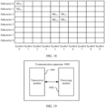
- FIG. 1 shows division of time-frequency resources in OFDM modulation.
- OFDM modulation a time-frequency resource of a system is divided into two-dimensional time-frequency grids.
- a frequency domain resource (or a system bandwidth) is divided into a plurality of parallel subcarriers by using a subcarrier (subcarrier) as a granularity.
- FIG. 1 shows 512 subcarriers (including subcarriers 0 to 511).
- a time domain resource is divided into a plurality of consecutive symbols by using a symbol (symbol) as a granularity.
- FIG. 1 shows eight symbols (including symbols 0 to 7).
- a time-frequency resource with duration of one symbol and a frequency width of one subcarrier is referred to as a resource element (resource element, RE).
- RE resource element
- one grid in FIG. 1 is one RE.
- Each RE may be used to carry one signal in OFDM modulation, to implement data receiving and sending.
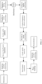
- FIG. 2 shows a transmitting procedure and a receiving procedure in OFDM modulation.
- a transmitter first maps a to-be-transmitted bit stream to a symbol through modulation (modulation).
- modulation Common modulation manners include: binary phase shift keying (binary phase shift keying, BPSK), pi/2-BPSK, quadrature phase shift keying (quadrature phase shift keying, QPSK), pi/4 QPSK, 8-phase shift keying (8 phase shift keying, 8PSK), 16PSK, quadrature amplitude modulation (quadrature amplitude modulation, QAM), 16QAM, 64QAM, and the like.
- the transmitter may map each modulation symbol to a corresponding subcarrier through serial-to-parallel conversion (SIPO/PISO, S/P), and convert data on each subcarrier into a time domain signal through inverse fast Fourier transform (inverse fast Fourier transform, IFFT).
- the transmitter adds a cyclic prefix (cyclic prefix, CP) to the time domain signal, and transmits, to a channel, a corresponding signal on which parallel-to-serial conversion (PISO/SIPO, P/S), digital-to-analog (digital-to-analog, DA) conversion, and up-conversion are performed.
- a receiver may receive a signal with interference.
- the receiver may further generate a frequency offset due to a deviation of a local oscillator.
- the receiver may perform analog-to-digital conversion and carrier frequency offset correction (carrier frequency offset correction, CFO correction) on the signal with interference and a frequency offset.
- the receiver may sequentially perform parallel-to-serial conversion, cyclic prefix removal, and fast Fourier transform (fast Fourier transform, FFT) on the signal with interference filtered out, to obtain a frequency domain signal.
- FFT fast Fourier transform
- the receiver performs digital signal processing such as phase tracking, serial-to-parallel conversion, demodulation (demodulation), and decoding on the frequency domain signal, to obtain sent data.
- receiver and the transmitter are relative concepts.
- One device may be used only as a receiver or a transmitter, or may be used as both a receiver and a transmitter. This is not specifically limited in this application.
- power saving In mobile communication (mobile communication), power saving (or referred to as energy saving) is one of important objectives that the terminal needs to achieve. Standby time of some forms of terminals, such as mobile phones or wearable devices, greatly affects user experience. Some other forms of terminals, such as wireless industrial sensors, are designed to work for several years without replacing batteries because of difficulty in battery replacement.
- a current implementation is to enable the terminal to work in different states (or modes), such as a connected (connected) state, an idle (idle) state, and an inactive (inactive) state according to different service requirements.
- states or modes
- the terminal may work in the connected state.
- signaling may be exchanged and data may be received and sent between the terminal and a network device.
- power consumption of the terminal is high, which is not conducive to energy saving.
- the terminal may work in the idle (idle) state or the inactive (inactive) state.
- the terminal enables a circuit to enter a sleep state and periodically wake up to detect whether there is data to be sent to the terminal. If there is data to be sent to the terminal, the terminal enters the connected state; otherwise, the terminal remains in the idle state or the inactive state, to continue to sleep. Power consumption of the terminal in the idle state or the inactive state is much lower than that in the connected state. Usually, the terminal is in the idle state or the inactive state for a longer time. For example, a user uses a mobile phone for four hours a day, and duration for which the mobile phone stays in a connected state is four hours; and the mobile phone is in an idle state or an inactive state for the other 20 hours. Therefore, power consumption of the terminal in the idle state or the inactive state determines standby time of the terminal to a great extent, and determines whether the terminal can achieve an objective of energy saving.
- FIG. 3 shows a receiver architecture in which a terminal is used as an example.
- the terminal is divided into a main link (main radio) and wake-up radio (wake-up radio, WUR), namely, a wake-up link.
- main radio main link
- WUR wake-up radio
- the main link may be understood as a link used when the terminal normally receives and sends data, or a link used when the terminal transmits data in the connected state. Power consumption of the main link is high.
- a signal received and sent by the terminal over the main link may be referred to as being transmitted over the main link, which represents a connection relationship between the terminal and another device, for example, a network device or another terminal.
- the main link is a logical concept rather than a physical entity. It may be understood that the main link is merely an example name, and a specific name of the main link does not limit the protection scope of this application.
- the main link may also be described as a first link.
- the first link may alternatively be replaced with a first circuit, a first state, a first mode, a first module, or the like.
- the main link for uniform description.
- the wake-up link may be understood as a link used by the terminal in the idle state or the inactive state, or may be understood as a separate low-power small circuit.
- the low-power small circuit may be implemented by using a separate small circuit or chip with a simple structure, and has low power consumption.
- the wake-up link is merely a name for differentiation, and a specific name of the wake-up link does not limit the protection scope of this application.
- the wake-up link may also be described as a second link.
- the second link may alternatively be replaced with a second circuit, a second state, a second mode, a second module, or the like.
- the following uses the wake-up link for uniform description.
- a signal received and sent by the terminal over the wake-up link may be referred to as being transmitted over the wake-up link, which represents a connection relationship between the terminal and another device, for example, a network device or another terminal.
- the wake-up link is a logical concept rather than a physical entity.
- the signal received and sent by the terminal over the wake-up link may be referred to, for example, as a wake-up signal/radio (wake up signal/radio, WUS/WUR).
- WUR signal may include a paging-related signal.
- the WUR signal may include a wake-up signal, and may further include a synchronization signal.
- the wake-up signal at least indicates paging-related information (for example, indicates information about a terminal that needs to perform receiving).
- Receiving the WUR signal (for example, the wake-up signal) over the wake-up link may be understood as working on the wake-up link, receiving the wake-up signal over the wake-up link, receiving the wake-up signal over the first link, or the like.
- the main link is disabled, and the wake-up link is enabled. In this case, power consumption is very low, and effect of power saving can be achieved.
- the network device needs to send a service to the terminal, the network device needs to send a wake-up signal to the wake-up link. After receiving the wake-up signal over the wake-up link, the terminal is triggered to start the main link, enter the connected state, and then perform normal data receiving and sending.
- FIG. 4 shows a specific architecture of the wake-up link of the terminal in FIG. 3 .
- the synchronization signal is used as an example.
- the terminal After receiving the synchronization signal, the terminal first performs radio frequency filtering on the synchronization signal based on a radio frequency filter, and then amplifies a filtered synchronization signal based on a low noise amplifier, to obtain an amplified synchronization signal. Then, the terminal may perform, based on a frequency mixer (as shown by a multiplication sign in FIG.
- a process in which the terminal performs the down-conversion on the amplified synchronization signal based on the frequency mixer may be: The terminal performs, based on the frequency mixer, a multiplication operation on the amplified synchronization signal and the signal generated by the local oscillator (local oscillator, LO), to implement down-conversion.
- LO local oscillator
- an expression of a baseband signal is s wur ( t ) .
- the network device or another terminal modulates the baseband signal to a high-frequency carrier frequency.
- the carrier frequency may be represented as s wur ( t ) e j2 ⁇ f c t , where f c is a frequency (for example, 3 GHz) of the carrier frequency, and t is time.
- the terminal may perform, based on the frequency mixer, a multiplication operation on a single-frequency signal generated by the local oscillator and the carrier frequency, to restore the high-frequency carrier frequency to the baseband signal, thereby achieving the objective of down-conversion.
- a frequency of the single-frequency signal corresponds to the carrier frequency, and may be represented as e j2 ⁇ f c t
- a multiplication operation performed by the frequency mixer is a signal obtained after a conjugate is multiplied. It can be learned from the formula that a correct baseband signal can be demodulated only when the single-frequency signal generated by the local oscillator of the terminal is the same as the carrier frequency used by the network device for frequency modulation.
- a carrier frequency of a synchronization signal that is modulated by the network device and that is sent to the terminal is high, and a high-performance local oscillator and a high-performance frequency mixer are needed to generate a same single-frequency signal as the synchronization signal, to implement correct demodulation.
- the high-performance local oscillator and the high-performance frequency mixer consume a large amount of power.
- some low-power components are usually used for the wake-up link. Performance indicators of these low-power components are poor. For example, for a low-power local oscillator, a single-frequency signal generated by the local oscillator has a larger frequency offset (referred to as a frequency offset).
- the local oscillator needs to generate a single-frequency signal with a frequency of f c , which may be represented as e j2 ⁇ f c t .
- the local oscillator actually generates a frequency of f c + f offset , which may be represented as e j2 ⁇ ( f c + foffset ) t .
- a transmitter and a receiver need to implement time synchronization first to complete a receiving and sending process.
- Synchronization means that a receiver needs to find a boundary of a received signal.
- An OFDM system is used as an example.
- the receiver for example, a terminal, needs to find a start position and an end position of each symbol in the received signal.
- a common transmitter for example, a network device or another terminal, sends a synchronization signal.
- the synchronization signal is generally designed as a signal obtained through modulation based on a signal sequence.
- the signal sequence is usually a sequence having a good autocorrelation characteristic, and is also referred to as a synchronization sequence.
- the terminal may locally store the synchronization sequence in advance, and perform sliding correlation with the received signal by using a local synchronization sequence.
- a synchronization sequence that slides into the received signal is aligned with the local synchronization sequence at a moment, a significant correlation peak appears, so that it is determined that the moment is a moment at which the transmitter and the receiver are aligned, thereby completing device synchronization.
- the following specifically describes a synchronization process of the terminal with reference to FIG. 5 .
- FIG. 5 shows a time domain position relationship between a synchronization signal and a data signal.
- a signal sequence of the synchronization signal is s sync ( n ), where 0 ⁇ n ⁇ N sym , and N sym is a quantity of sampling points of an analog-to-digital converter of the terminal. Because the terminal does not know a specific position of the synchronization sequence in advance, the terminal may perform sliding correlation on the received signal by using a sliding window whose length is N sym sampling points.
- Sliding correlation means that the terminal performs an interception on a sampled sequence based on the sliding window, and after performing a correlation operation on an intercepted signal, the terminal may slide the sliding window by one sampling point in a direction indicated by an arrow in FIG. 5 , and then perform a next interception and correlation operation.
- Each interception operation based on the sliding window means to intercept N sym sampling points from corresponding positions in the signal, and a sequence obtained through sampling may be represented as r ( n ).
- An l th sliding is used as an example.
- a significant correlation peak appears.
- a time domain position of the correlation peak is an alignment position, or an alignment moment.
- the existence of the frequency offset has serious impact on a correlation result.
- a correlation sequence has a good autocorrelation characteristic, that is, a correlation peak may be obtained when a present sequence correlates with the present sequence.
- a frequency offset a sequence having a frequency offset correlates with the present sequence, the autocorrelation characteristic is damaged, and there is no obvious correlation peak.
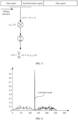
- the OFDM system is used as an example. FIG.
- embodiments of this application provide the following technical solutions, to ensure synchronization performance of a device in a sleep state.
- a wireless fidelity (wireless fidelity, Wi-Fi) system a vehicle to everything (vehicle to everything, V2X) communication system
- a device-to-device (device-to-device, D2D) communication system an internet of vehicles communication system
- 4th generation (4th generation, 4G) mobile communication system such as a long term evolution (long term evolution, LTE) system and a 5th generation (5th generation, 5G) mobile communication system, for example, a new radio (new radio, NR) system
- a future communication system such as a 6th generation (6th generation, 6G) communication system.
- the future communication system may also be named in another manner, which is still covered in the scope of this application. This is not limited in this application.
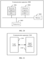
- FIG. 8 is a schematic diagram of an architecture of a communication system to which a communication method according to embodiments of this application is applicable.
- the communication system includes a terminal and a network device.
- the terminal is a terminal that accesses a network and has a wireless transceiver function, or a chip or a chip system that may be disposed in the terminal.
- the terminal may also be referred to as user apparatus (user equipment, UE), an access terminal, a subscriber unit (subscriber unit), a subscriber station, a mobile station (mobile station, MS), a remote station, a remote terminal, a mobile device, a user terminal, a terminal, a wireless communication device, a user agent, or a user apparatus.
- the terminal in embodiments of this application may be a mobile phone (mobile phone), a cellular phone (cellular phone), a smartphone (smartphone), a tablet computer (Pad), a wireless data card, a personal digital assistant (personal digital assistant, PDA), a wireless modem (modem), a handset (handset), a laptop computer (laptop computer), a machine type communication (machine type communication, MTC) terminal, a computer having a wireless transceiver function, a virtual reality (virtual reality, VR) terminal, an augmented reality (augmented reality, AR) terminal, a wireless terminal in industrial control (industrial control), a wireless terminal in self-driving (self-driving), a wireless terminal in remote medical (remote medical), a wireless terminal in a smart grid (smart grid), a wireless terminal in transportation safety (transportation safety), a wireless terminal in a smart city (smart city), a wireless terminal in a smart home (smart home), a vehicle-mounted terminal, a road side unit (road
- the terminal in this application may alternatively be a vehicle-mounted module, a vehicle-mounted subassembly, a vehicle-mounted component, a vehicle-mounted chip, or a vehicle-mounted unit that is built in a vehicle as one or more components or units.
- the network device for example, an access network device, is a device that is located on a network side of the communication system and has a wireless transceiver function, or a chip or a chip system that may be disposed in the device.
- the network device may include a next-generation mobile communication system, for example, a 6G access network device, for example, a 6G base station, or a 6G core network element.
- the network device may be named in another manner, which falls within the protection scope of embodiments of this application. This is not limited in this application.
- the network device may alternatively include 5G, for example, a gNB in an NR system, or one or a group of (including a plurality of antenna panels) antenna panels of a base station in 5G, or may be a network node that forms a gNB, a transmission point (transmission and reception point, TRP, or transmission point, TP), or a transmission measurement function (transmission measurement function, TMF), for example, a baseband unit (baseband unit, BBU), a central unit (central unit, CU) or a distributed unit (distributed unit, DU), an RSU having a base station function, a wired access gateway, or a 5G core network element.
- 5G for example, a gNB in an NR system, or one or a group of (including a plurality of antenna panels) antenna panels of a base station in 5G, or may be a network node that forms a gNB, a transmission point (transmission and reception point, TRP, or transmission point, TP
- the network device may further include an access point (access point, AP), a wireless relay node, a wireless backhaul node, macro base stations in various forms, a micro base station (also referred to as a small cell), a relay station, an access point, a wearable device, a vehicle-mounted device, and the like in a wireless fidelity (wireless fidelity, Wi-Fi) system.
- access point access point
- AP access point
- wireless relay node wireless backhaul node
- macro base stations in various forms
- a micro base station also referred to as a small cell
- a relay station an access point
- a wearable device wearable device
- vehicle-mounted device and the like in a wireless fidelity (wireless fidelity, Wi-Fi) system.
- wireless fidelity wireless fidelity
- the communication method according to embodiments of this application is applicable to communication between a first device and a second device.
- the first device and the second device may be the terminal or the network device in the communication system shown in FIG. 8 .
- the first device is the terminal, and the second device is the network device.
- both the first device and the second device are network devices.
- both the first device and the second device are terminals.
- the first device is the network device, and the second device is the terminal.
- the first device may send a signal including a synchronization signal and a reference frequency signal.
- the second device may eliminate, based on a frequency offset generated by the reference frequency signal in a demodulation process, a frequency offset generated by the synchronization signal in the demodulation process, to accurately determine a time domain position of a correlation peak, complete device synchronization, and ensure synchronization performance of a device in a sleep state.
- FIG. 9 shows a procedure of a communication method according to an embodiment of this application.
- the communication method includes S901, S902, and S903.
- a first device determines a first signal.
- the first signal includes a first synchronization signal and N reference frequency signals, where N is a positive integer.
- the first synchronization signal is used for device synchronization, for example, used by the second device to implement synchronization with the first device based on the first synchronization signal.
- the first synchronization signal may be represented as s sync ( t ), where 0 ⁇ t ⁇ T sym , and T sym is duration of the first synchronization signal.
- the N reference frequency signals are used to eliminate a frequency offset generated by the first synchronization signal in a demodulation process, to implement device synchronization more accurately.
- Each of the N reference frequency signals may be a signal of a single frequency.
- an i th reference frequency signal in the N reference frequency signals may be represented as e j2 ⁇ f i t , where i is any integer ranging from 1 to N, f i is a frequency of the i th reference frequency signal, 0 ⁇ t ⁇ T sym , and T sym is duration of the i th reference frequency signal.
- the duration of the first synchronization signal is the same as the duration of the i th reference frequency signal, or it may be understood that the duration of the first synchronization signal is approximately the same as the duration of the i th reference frequency signal. It may be understood that the duration of the first synchronization signal being the same as the duration of the i th reference frequency signal is merely an example. This is not limited. For example, the duration of the first synchronization signal may alternatively be different from the duration of the i th reference frequency signal.
- frequency domain positions or time domain positions of the N reference frequency signals may be the same or different, which is described in detail in the following.
- At least two of the N reference frequency signals are located at different frequency domain positions, for example, located at consecutive or non-consecutive frequency domain positions. It may alternatively be considered that the at least two reference frequency signals have different frequencies.
- a frequency response of a radio channel is not always flat and fluctuates with an environment.
- fading occurs at a frequency, for example, deep fading (deep fading for short) occurs, it is difficult to eliminate the frequency offset of the first synchronization signal by using a reference frequency signal at a deep fading frequency. Consequently, it is difficult to determine the time domain position of the correlation peak, and the synchronization performance of the device in the sleep state cannot be ensured.
- the at least two reference frequency signals are located at different frequencies, and a possibility for deep fading to occur at these frequencies is low.
- a frequency offset of a reference frequency signal at a non-deep fading frequency may be used to eliminate the frequency offset of the first synchronization signal and complete the device synchronization, to further ensure the synchronization performance of the device in the sleep state, provided that deep fading does not occur at one frequency. This is also called frequency diversity gain. It should be noted that, for a specific implementation principle of eliminating the frequency offset of the first synchronization signal based on the frequency offset of the reference frequency signal, refer to related descriptions in "S903". Details are not described herein again. Two reference frequency signals are used as an example.
- a reference frequency signal 1 is located at a frequency 1, and a reference frequency signal 2 is located at a frequency 2. If deep fading occurs on the frequency 1, the reference frequency signal 2 on the frequency 2 may be used to eliminate the frequency offset of the first synchronization signal, to complete the device synchronization. Similarly, if deep fading occurs on a channel 2, the reference frequency signal 1 on the frequency 1 may be used to eliminate the frequency offset of the first synchronization signal, to complete the device synchronization.
- the at least two reference frequency signals are located at a same time domain position. In this way, time domain resources can be saved, and resource utilization and communication efficiency can be improved.
- the at least two reference frequency signals can generate frequency offsets closer to the frequency offset of the first synchronization signal, to eliminate the frequency offset of the first synchronization signal as much as possible, and further ensure the synchronization performance of the device in the sleep state.
- the two reference frequency signals are used as an example.
- the reference frequency signal 1 is located at the frequency 1
- the reference frequency signal 2 is located at the frequency 2
- the reference frequency signal 1 and the reference frequency signal 2 are located at a time unit 1.
- the time unit may be a symbol, a slot (slot), a mini-slot (mini-slot), a subframe (subframe), a radio frame (radio frame), or the like. This is not specifically limited in this application.
- At least two of the N reference frequency signals are located at different time domain positions.
- the two reference frequency signals are used as an example.
- the reference frequency signal 1 is located at the frequency 1
- the reference frequency signal 2 is located at the frequency 2
- the reference frequency signal 1 is located at a time unit 1
- the reference frequency signal 2 is located at a time unit 2.
- a device for example, the second device
- at least two of the N reference frequency signals are located at consecutive time domain positions.
- some reference frequency signals in the N reference frequency signals are located at consecutive time domain positions, and the other reference frequency signals are respectively located at inconsecutive time domain positions. That is, there are time domain intervals among the other reference frequency signals.
- the N reference frequency signals are located at consecutive time domain positions, that is, time domain positions of two adjacent reference frequency signals in the N reference frequency signals are consecutive. In this way, sending the at least two reference frequency signals at consecutive time domain positions can ensure that the at least two reference frequency signals can generate frequency offsets that are closer to each other in a demodulation process as much as possible, to eliminate the frequency offset of the first synchronization signal as much as possible, and ensure the synchronization performance of the device in the sleep state as much as possible.
- the two reference frequency signals are used as an example. On a basis that the reference frequency signal 1 is located at the frequency 1, and the reference frequency signal 2 is located at the frequency 2, the reference frequency signal 1 is located at a time unit 1, and the reference frequency signal 2 is located at a time unit 2.
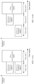
- time domain positions of the first synchronization signal and the N reference frequency signals are different.
- the time domain position of the first synchronization signal does not overlap a time domain position of any one of the N reference frequency signals.
- the first synchronization signal and the N reference frequency signals are located at consecutive time domain positions.
- two reference frequency signals are used as an example.
- the first synchronization signal is located at a time unit 1
- a reference frequency signal 1 is located at a time unit 2
- a reference frequency signal 2 is located at a time unit 3.
- the first synchronization signal and the N reference frequency signals are respectively located at inconsecutive time domain positions.
- the first synchronization signal is located at a time unit 1
- a reference frequency signal 1 is located at a time unit 3
- a reference frequency signal 2 is located at a time unit 4.
- the time domain positions of the N reference frequency signals may be located before the time domain position of the first synchronization signal.
- two reference frequency signals are used as an example.
- a reference frequency signal 1 and a reference frequency signal 2 are located at a time unit 1, and the first synchronization signal is located at a time unit 2.
- two reference frequency signals are used as an example.
- a reference frequency signal 1 is located at a time unit 1
- a reference frequency signal 2 is located at a time unit 2
- the first synchronization signal is located at a time unit 3.
- the time domain positions of the N reference frequency signals may be located after the time domain position of the first synchronization signal.
- two reference frequency signals are used as an example.
- the first synchronization signal is located at a time unit 1
- a reference frequency signal 1 and a reference frequency signal 2 are located at a time unit 2.
- two reference frequency signals are used as an example.
- the first synchronization signal is located at a time unit 1
- a reference frequency signal 1 is located at a time unit 2
- a reference frequency signal 2 is located at a time unit 3.
- time domain positions of some reference frequency signals in the N reference frequency signals may be located before the time domain position of the first synchronization signal, and time domain positions of the other reference frequency signals in the N reference frequency signals may be located after the time domain position of the first synchronization signal.
- two reference frequency signals are used as an example.
- a reference frequency signal 1 is located at a time unit 1
- the first synchronization signal is located at a time unit 2
- a reference frequency signal 2 is located at a time unit 3.
- That the first device determines the first signal may mean that the first device modulates a first sequence, for example, modulates the first sequence based on OFDM, to obtain the first signal.
- the first sequence may include a first synchronization sequence and N reference frequency sequences.
- the first synchronization sequence may be selected from sequences having good autocorrelation characteristics. For example, these sequences having good autocorrelation characteristics may be Zadoff Chu sequences or Gold sequences.
- the first synchronization sequence may be pre-configured locally on the first device, or may be obtained by the first device from another device in advance.
- the first synchronization sequence is used to obtain the first synchronization signal through modulation, and the first synchronization signal may be represented as s sync ( n ), where 0 ⁇ n ⁇ N sym , and N sym is a quantity of sampling points of a digital-to-analog converter of the first device.
- the first device performs OFDM modulation and digital-to-analog conversion on the first synchronization sequence, and modulates discrete synchronization sequences into continuous signals, to obtain the first synchronization signal.
- the N reference frequency sequences are used to obtain N reference frequency signals through modulation.
- An i th reference frequency sequence in the N reference frequency sequences may be represented as e j 2 ⁇ f i f s n , where f s is a sampling frequency of the digital-to-analog converter of the first device.
- the first device performs OFDM modulation on the i th reference frequency sequence, modulates N sym discrete reference frequency sequences into consecutive signals, and maps the consecutive signals to a carrier frequency fi, to obtain the i th reference frequency signal.
- the carrier frequency f i may be any frequency in a bandwidth occupied by WUR. This is not specifically limited in embodiments of this application.
- OFDM modulation used in this embodiment of this application is merely an example. In this embodiment of this application, any other possible modulation scheme may be used. This is not specifically limited herein.
- the first device sends the first signal, and correspondingly, the second device receives the first signal.
- the synchronization signal may be carried on a first time-frequency resource.
- the first time-frequency resource is a time-frequency resource corresponding to a wake-up link.
- the first time-frequency resource is merely an example naming manner, and may alternatively be replaced with a first frequency, a first resource, a first resource set, a first time-frequency resource set, or the like. This is not specifically limited in this application.
- a time-frequency resource corresponding to a main link may be referred to as a second time-frequency resource.
- the second time-frequency resource is merely an example naming manner, and may alternatively be replaced with a second frequency, a second resource, a second resource set, a second time-frequency resource set, or the like. This is not specifically limited in this application.
- S903 The second device parses the first signal.
- That the second device parses the first signal may be considered as that the second device performs analysis processing on the first signal; or may be understood as that the second device demodulates the first signal, to determine the time domain position of the correlation peak.
- the second device demodulates the first signal to obtain a synchronization sequence having a frequency offset and N reference frequency sequences having frequency offsets.
- the synchronization sequence having the frequency offset is a sequence obtained by demodulating the first synchronization signal.
- the first synchronization signal is represented as s sync ( t ), where 0 ⁇ t ⁇ T sym , and T sym is duration of the first synchronization signal.
- the second device may perform down-conversion on the first synchronization signal based on a low-power local oscillator and a frequency mixer, to obtain a frequency offset synchronization signal.
- the frequency offset synchronization signal may be represented as s sync ( t ) e j2 ⁇ f offsett , where f offset is a frequency offset of the low-power local oscillator.
- the second device may sample the frequency offset synchronization signal based on an analog-to-digital converter, to obtain the synchronization sequence having the frequency offset.
- the synchronization sequence having the frequency offset may be represented as s sync n e j 2 ⁇ f offset f s n , where f s is a sampling frequency of the analog-to-digital converter, 0 ⁇ n ⁇ N sym , and N sym is a quantity of sampling points of the analog-to-digital converter of the second device.
- the i th reference frequency signal is represented as e j2 ⁇ fit , where f i is a frequency of the i th reference frequency signal, 0 ⁇ t ⁇ T sym , and T sym is duration of the i th reference frequency signal.
- the second device may perform down-conversion on the i th reference frequency signal based on the low-power local oscillator and the frequency mixer, to obtain an i th frequency offset reference frequency signal.
- the i th frequency offset reference frequency signal may be represented as e j 2 ⁇ ( f i + foffset ) t , where f offset is a frequency offset of the low-power local oscillator.
- the second device may sample the frequency offset synchronization signal based on an analog-to-digital converter, to obtain the synchronization sequence having the frequency offset.
- the synchronization sequence having the frequency offset may be represented as s sync n e j 2 ⁇ f offset f s n , where f s is a sampling frequency of the analog-to-digital converter, 0 ⁇ n ⁇ N sym , and N sym is a quantity of sampling points of the analog-to-digital converter of the second device. It may be understood that, for a specific demodulation procedure described in this embodiment of this application, refer to the related descriptions in the foregoing "1. OFDM" and "3. Main link and wake-up link". Details are not described again.
- the second device may determine the time domain position of the correlation peak based on the synchronization sequence having the frequency offset, the N reference frequency sequences having the frequency offsets, the first synchronization sequence, and the N reference frequency sequences. Specifically, the second device may first eliminate a frequency offset based on the synchronization sequence having the frequency offset and the N reference frequency sequences having the frequency offsets. For example, the second device multiplies the synchronization sequence having the frequency offset by a conjugate transpose of an i th reference frequency sequence having a frequency offset, to obtain an i th conjugate transpose sequence, that is, a sequence whose frequency offset is eliminated.
- the second device then accurately determines the time domain position of the correlation peak based on the first synchronization sequence and the N reference frequency sequences. For example, the second device performs a correlation operation on the i th conjugate transpose sequence, the first synchronization sequence, and an i th reference frequency sequence, to obtain an exact time domain position of the correlation peak.
- a conjugate transpose multiplication may be: a sequence obtained after a conjugate of the i th reference frequency sequence having the frequency offset is multiplied by the synchronization sequence having the frequency offset, or a sequence obtained after a conjugate of the synchronization sequence having the frequency offset is multiplied by the i th reference frequency sequence having the frequency offset.
- the synchronization sequence having the frequency offset is represented as s sync n e j 2 ⁇ f offset f s n
- the sequence obtained after the conjugate of the i th reference frequency sequence having the frequency offset is represented as e j 2 ⁇ ⁇ f i + f offset f s n .
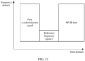
- Case 1 There is one reference frequency signal (denoted as a reference frequency signal 1).
- FIG. 12 shows a time-frequency position relationship between the reference frequency signal 1 and the first synchronization signal
- FIG. 13 shows a time domain position relationship between the reference frequency signal 1 and the first synchronization signal.
- the reference frequency signal 1 and the first synchronization signal are located at consecutive time domain positions.
- the second device may perform sliding sampling on a down-converted signal based on the digital-to-analog converter. Because the reference frequency signal and the first synchronization signal occupy two time domain positions in total, the second device may use two sliding windows (denoted as a first sliding window and a second sliding window) to perform sliding sampling on the down-converted signal.
- a length of the first sliding window matches duration of the first synchronization signal
- a length of the second sliding window matches duration of the reference frequency signal 1.
- a time domain position relationship between the first sliding window and the second sliding window matches the time domain position relationship between the reference frequency signal 1 and the first synchronization signal.
- a spacing between the first sliding window and the second sliding window is the same as a spacing between the first synchronization signal and the reference frequency signal 1.
- the first sliding window and the second sliding window are located in consecutive time domain positions.
- the second device may slide the first sliding window and the second sliding window by one sampling point in a direction indicated by an arrow in FIG. 13 , and then perform next sampling.
- Each sliding sampling based on the first sliding window and the second sliding window means to separately intercept N sym sampling points from corresponding positions in a signal, to obtain respective sampling sequences.
- An l th sliding is used as an example.
- the second device performs a correlation operation on the conjugate transpose sequence, and a first synchronization sequence and a reference frequency sequence 1 that are pre-stored by the second device, to obtain one correlation value.
- one correlation value is obtained every time one sampling point is slid, and the correlation peak is detected based on the correlation value.
- the second sliding window is slid to a position that coincides with a down-converted reference frequency signal 1.
- the second device may multiply the synchronization sequence having the frequency offset by a conjugate transpose of the reference frequency sequence 1 having the frequency offset, to obtain a conjugate transpose sequence.
- the second device performs a correlation operation on the conjugate transpose sequence, and the first synchronization sequence and the reference frequency sequence 1 that are pre-stored by the second device, to obtain a maximum correlation value.
- the second device may determine the time domain position of the correlation peak, that is, an aligned position, based on the correlation value, to implement synchronization.
- Case 2 There are two reference frequency signals (denoted as a reference frequency signal 1 and a reference frequency signal 2), and the reference frequency signal 1 and the reference frequency signal 2 are located at different time domain positions.
- FIG. 14 shows a time-frequency position relationship among the reference frequency signal 1, the reference frequency signal 2, and the first synchronization signal
- FIG. 15 shows a time domain position relationship among the reference frequency signal 1, the reference frequency signal 2, and the first synchronization signal.
- the reference frequency signal 1, the reference frequency signal 2, and the first synchronization signal are located at consecutive time domain positions.
- the second device may perform sliding sampling on a down-converted signal based on the digital-to-analog converter.
- the second device may use three sliding windows (denoted as a first sliding window, a second sliding window, and a third sliding window) to perform sliding sampling on the down-converted signal.
- a length of the first sliding window matches duration of the first synchronization signal
- a length of the second sliding window matches duration of the reference frequency signal 1
- a length of the third sliding window matches duration of the reference frequency signal 3.
- a time domain position relationship among the first sliding window, the second sliding window, and the third sliding window matches the time domain position relationship among the reference frequency signal 1, the reference frequency signal 2, and the first synchronization signal.
- a spacing between the first sliding window and the second sliding window is the same as a spacing between the first synchronization signal and the reference frequency signal 1.
- a spacing between the first sliding window and the third sliding window is the same as a spacing between the first synchronization signal and the reference frequency signal 2.
- the first sliding window, the second sliding window, and the third sliding window are sequentially located in consecutive time domain positions.
- the second device may slide the first sliding window, the second sliding window, and the third sliding window by one sampling point in a direction indicated by an arrow in FIG. 15 , and then perform next sampling.
- Each sliding sampling based on the first sliding window, the second sliding window, and the third sliding window means to separately intercept N sym sampling points from corresponding positions in a signal, to obtain respective sampling sequences.
- An l th sliding is used as an example.
- the second device performs a correlation operation on the conjugate transpose sequence 1, and a first synchronization sequence and a reference frequency sequence that are pre-stored by the second device, to obtain one correlation value 1.
- the second device performs a correlation operation on the conjugate transpose sequence 2, and the first synchronization sequence and a reference frequency sequence that are pre-stored by the second device, to obtain one correlation value 2.
- two correlation values may be obtained every time one sampling point is slid, and the correlation peak is detected based on the two correlation values.
- the first sliding window is slid to a position that coincides with a down-converted first synchronization signal
- the second sliding window is slid to a position that coincides with a down-converted reference frequency signal 1
- the third sliding window is slid to a position that coincides with a down-converted reference frequency signal 2.
- the second device may multiply the synchronization sequence having the frequency offset by a conjugate transpose of the reference frequency sequence 1 having the frequency offset, to obtain a conjugate transpose sequence 1.
- the second device may multiply the synchronization sequence having the frequency offset by a conjugate transpose of the reference frequency sequence 2 having the frequency offset, to obtain a conjugate transpose sequence 2.
- the second device performs a correlation operation on the conjugate transpose sequence 1, and the first synchronization sequence and the reference frequency sequence 1 that are pre-stored by the second device, to obtain one correlation value 1.
- the second device may also perform a correlation operation on the conjugate transpose sequence 2, and the first synchronization sequence and the reference frequency sequence 2 that are pre-stored by the second device, to obtain one correlation value 2.
- the second device may determine the time domain position of the correlation peak, that is, an aligned position, based on the correlation value 1 and the correlation value 2, to implement synchronization. For example, if the correlation value 1 is greater than a threshold used for detecting the correlation peak, and the correlation value 2 is less than the threshold, the time domain position of the correlation peak is determined based on the correlation value 1. Alternatively, if the correlation value 2 is greater than the threshold, and the correlation value 1 is less than the threshold, the time domain position of the correlation peak is determined based on the correlation value 2. Alternatively, if both the correlation value 1 and the correlation value 2 are greater than the threshold, the time domain position of the correlation peak is determined based on a larger value of the correlation value 1 and the correlation value 2.
- the correlation value 1 and the correlation value 2 are equal to the threshold is not limited in this application.
- the time domain position of the correlation peak may be determined based on the correlation value 1.
- the correlation value 1 is greater than the threshold, and the correlation value 2 is less than or equal to the threshold, the time domain position of the correlation peak may be determined based on the correlation value 1.
- Case 3 There are two reference frequency signals (denoted as a reference frequency signal 1 and a reference frequency signal 2), and the reference frequency signal 1 and the reference frequency signal 2 are located at a same time domain position.
- FIG. 16 shows a time-frequency position relationship among the reference frequency signal 1, the reference frequency signal 2, and the first synchronization signal
- FIG. 17 shows a time domain position relationship among the reference frequency signal 1, the reference frequency signal 2, and the first synchronization signal.
- the reference frequency signal 1 and the reference frequency signal 2 are located at a same time domain position, and the time domain position is consecutive to a time domain position of the first synchronization signal.
- the second device may perform sliding sampling on a down-converted signal based on the digital-to-analog converter.
- the second device may use two sliding windows (denoted as a first sliding window and a second sliding window) to perform sliding sampling on the down-converted signal.
- a length of the first sliding window matches duration of the first synchronization signal
- a length of the second sliding window matches duration of the reference frequency signal 1 and duration of the reference frequency signal 2.
- a time domain position relationship between the first sliding window and the second sliding window matches the time domain position relationship among the reference frequency signal 1, the reference frequency signal 2, and the first synchronization signal.
- a spacing between the first sliding window and the second sliding window is the same as a spacing between the first synchronization signal and the reference frequency signal 1.
- the spacing between the first sliding window and the second sliding window is also the same as a spacing between the first synchronization signal and the reference frequency signal 2.
- the first sliding window and the second sliding window are located in consecutive time domain positions.
- the second device may slide the first sliding window and the second sliding window by one sampling point in a direction indicated by an arrow in FIG. 17 , and then perform next sampling.
- Each sliding sampling based on the first sliding window and the second sliding window means to separately intercept N sym sampling points from corresponding positions in a signal, to obtain respective sampling sequences.
- An l th sliding is used as an example.
- the second device performs a correlation operation on the conjugate transpose sequence, and a first synchronization sequence and a reference frequency sequence 1 that are pre-stored by the second device, to obtain one correlation value 1.
- the second device performs a correlation operation on the conjugate transpose sequence, and the first synchronization sequence and a reference frequency sequence 2 that are pre-stored by the second device, to obtain one correlation value 2.
- two correlation values may be obtained every time one sampling point is slid, and the correlation peak is detected based on the two correlation values.
- the second sliding window is slid to a position that coincides with a down-converted reference frequency signal 1 and a down-converted reference frequency signal 2.
- the second device may multiply the synchronization sequence having the frequency offset by a conjugate transpose of the superimposed sequence, to obtain a conjugate transpose sequence.
- the second device may perform a correlation operation on the conjugate transpose sequence, and the first synchronization sequence and the reference frequency sequence 1 that are pre-stored by the second device, to obtain one correlation value 1.
- the second device may also perform a correlation operation on the conjugate transpose sequence, and the first synchronization sequence and the reference frequency sequence 2 that are pre-stored by the second device, to obtain one correlation value 2.
- the second device may also determine the time domain position of the correlation peak based on the correlation value 1 and the correlation value 2.
- the correlation value 2 refer to the related descriptions in the foregoing "Case 2". Details are not described again.
- the first signal includes the first synchronization signal and the N reference frequency signals, and each reference frequency signal is the signal of the single frequency.
- each reference frequency signal may generate a frequency offset close to that of the first synchronization signal, thereby eliminating the frequency offset of the first synchronization signal.
- a device performs a correlation operation by using a synchronization signal without a frequency offset, so that a time domain position of a correlation peak can be accurately determined, thereby completing device synchronization, and ensuring synchronization performance of the device in a sleep state.
- the communication method according to this embodiment of this application may further include: The first device sends a wake-up signal, and correspondingly, the second device receives the wake-up signal.
- the wake-up signal may be carried over a wake-up link, and data in the wake-up signal is used to wake up the second device, to trigger the second device to start a main link and enter a connected state.
- the data in the wake-up signal may be carried in a combination of on states or off states of resource units in a resource unit set, and the resource unit set belongs to the first time-frequency resource. It may be understood that, carrying the data based on the combination of the on states or the off states of the resource units may implement resource multiplexing, thereby improving communication efficiency and spectral efficiency.
- the resource unit may occupy at least one OFDM symbol in time, and the resource unit may occupy at least one OFDM subcarrier in frequency.
- a granularity of the resource unit may be selected based on an actual scenario.
- the resource unit may be an RE or a resource block (resource block, RB), to ensure that the resource unit is applicable to the actual scenario.
- the data in the wake-up signal includes at least one bit (bit), and a combination of on states or off states of every two resource units in the resource unit set is used to transmit one corresponding bit in the at least one bit.
- bit bit
- a first combination a first resource unit is in an on state, and a second resource unit is in an off state, and the first combination is used to transmit a bit "1".
- a first resource unit is in an off state, and a second resource unit is in an on state, and the second combination is used to transmit a bit "0", that is, binary on-off keying (on-off keying, OOK) modulation.
- FIG. 18 shows time-frequency domain distribution of the resource unit set.
- the resource unit set includes 80 REs including 10 symbols and 8 subcarriers, and each RE is one resource unit.
- An RE 0,0 (which represents an RE including a subcarrier 0 and a symbol 0, and the same applies below) and an RE 0,1 are used as an example.
- the RE 0,0 is in an on state
- the RE 0.1 is in an off state
- a bit 1 is transmitted.
- the RE 0,0 is in an off state
- the RE 0,1 is in an on state
- a bit 0 is transmitted.
- the second device may determine, based on a resource unit, a value of a corresponding bit by comparing energy of the resource units, and does not need to determine a capability threshold of a single resource unit, thereby reducing complexity of demodulation, which improves operation efficiency of the second device and is more conducive to energy saving.
- the data in the wake-up signal includes at least one bit, and a combination of on states or off states of every two resource unit groups (one resource unit group includes a plurality of resource units) in the resource unit set is used to transmit one corresponding bit in the at least one bit.
- a combination of on states or off states of every two resource unit groups are used to transmit one corresponding bit in the at least one bit.
- a second combination all resource units in a first resource unit group are in an off state, and all resource units in a second resource unit group are in an on state, and the second combination is used to transmit a bit "0".
- an RE 4,2 and an RE 5,3 are one resource unit group
- an RE 4,3 and an RE 5,2 are another resource unit group.
- both the RE 4,2 and the RE 5,3 are in an on state
- both the RE 4,3 and the RE 5,2 are in an off state
- the first combination is used to transmit the bit "1".
- both the RE 4,2 and the RE 5,3 are in an off state, and both the RE 4,3 and the RE 5,2 are in an on state, and the second combination is used to transmit the bit "0".
- the second device may determine, based on a resource unit group, a value of a corresponding bit by comparing energy of the resource unit groups, and does not need to determine a capability threshold of a single resource unit, thereby reducing complexity of demodulation, which improves operation efficiency of the second device and is more conducive to energy saving.
- FIG. 19 is a schematic diagram 1 of a structure of a communication apparatus according to an embodiment of this application.
- a communication apparatus 1900 may be used in a first device shown in FIG. 9 , and includes various modules configured to perform a function of the first device in the method shown in FIG. 9 , for example, includes a transceiver module 1901 and a processing module 1902.
- the processing module 1902 is configured to determine a first signal; and the transceiver module 1901 is configured to send the first signal.
- the first signal is carried on a first time-frequency resource, and the first signal includes a first synchronization signal and N reference frequency signals, where N is a positive integer. Time domain positions of the first synchronization signal and the N reference frequency signals are different, and each of the N reference frequency signals is a signal of a single frequency.
- At least two of the N reference frequency signals are located at different frequency domain positions.
- At least two of the N reference frequency signals are located at a same time domain position.
- at least two of the N reference frequency signals are located at different time domain positions.
- At least two of the N reference frequency signals are located at consecutive time domain positions.
- an i th reference frequency signal in the N reference frequency signals is e j2 ⁇ f i t , where i is any integer ranging from 1 to N, f i is a frequency of the i th reference frequency signal, 0 ⁇ t ⁇ T sym , and T sym is duration of the i th reference frequency signal.
- the transceiver module 1901 is further configured to send a wake-up signal after sending the first signal.
- Data in the wake-up signal is carried in a combination of on states or off states of resource units in a resource unit set, and the resource unit set belongs to the first time-frequency resource.
- the resource unit occupies at least one orthogonal frequency division multiplexing OFDM symbol in time, and the resource unit occupies at least one OFDM subcarrier in frequency.
- the transceiver module 1901 may alternatively include a sending module and a receiving module (not shown in FIG. 19 ).
- the sending module is configured to implement a sending function of the communication apparatus 1900
- the receiving module is configured to implement a receiving function of the communication apparatus 1900.
- the communication apparatus 1900 may further include a storage module (not shown in FIG. 19 ).
- the storage module stores a program or instructions.
- the processing module executes the program or the instructions, the communication apparatus 1900 is enabled to implement the function of the first device in the method shown in FIG. 9 .
- the processing module included in the communication apparatus 1900 may be implemented by a processor or a processor-related circuit component, and may be a processor or a processing unit.
- the transceiver module may be implemented by a transceiver or a transceiver-related circuit component, and may be a transceiver or a transceiver unit.
- the communication apparatus 1900 may be a terminal or a network device, may be a chip (system) or another component or subassembly that may be disposed in a terminal or a network device, or may be an apparatus including a terminal or a network device. This is not limited in this application.
- a communication apparatus 1900 may be used in a second device shown in FIG. 9 , and includes various modules configured to perform a function of the second device in the method shown in FIG. 9 , for example, includes a transceiver module 1901 and a processing module 1902.
- the transceiver module 1901 is configured to receive a first signal; and the processing module 1902 is configured to parse the first signal.
- the first signal is carried on a first time-frequency resource, and the first signal includes a first synchronization signal and N reference frequency signals, where N is an integer. Time domain positions of the first synchronization signal and the N reference frequency signals are different, and each of the N reference frequency signals is a signal of a single frequency.
- At least two of the N reference frequency signals are located at different frequency domain positions.
- At least two of the N reference frequency signals are located at a same time domain position.
- at least two of the N reference frequency signals are located at different time domain positions.
- At least two of the N reference frequency signals are located at consecutive time domain positions.
- an i th reference frequency signal in the N reference frequency signals is e j2 ⁇ fit , where i is any integer ranging from 1 to N, f i is a frequency of the i th reference frequency signal, 0 ⁇ t ⁇ T sym , and T sym is duration of the i th reference frequency signal.
- the processing module 1902 is further configured to: demodulate the first signal to obtain a synchronization sequence having a frequency offset and N reference frequency sequences having frequency offsets; and determine a time domain position of a correlation peak based on the synchronization sequence having the frequency offset, the N reference frequency sequences having the frequency offsets, a first synchronization sequence, and N reference frequency sequences.
- the synchronization sequence having the frequency offset is a sequence obtained by demodulating the first synchronization signal
- an i th reference frequency sequence having a frequency offset in the N reference frequency sequences having the frequency offsets is a sequence obtained by demodulating the i th reference frequency signal in the N reference frequency signals
- i is any integer ranging from 1 to N.
- the first synchronization sequence is used to obtain the first synchronization signal through modulation
- the N reference frequency sequences are used to obtain the N reference frequency signals through modulation.
- the processing module 1902 is further configured to: multiply the synchronization sequence having the frequency offset by a conjugate transpose of the i th reference frequency sequence having the frequency offset, to obtain an i th conjugate transpose sequence; and perform a correlation operation on the i th conjugate transpose sequence, the first synchronization sequence, and an i th reference frequency sequence, to determine the time domain position of the correlation peak.
- the transceiver module 1901 is further configured to receive a wake-up signal after receiving the first signal.
- Data in the wake-up signal is carried in a combination of on states or off states of resource units in a resource unit set, and the resource unit set belongs to the first time-frequency resource.
- the resource unit occupies at least one OFDM symbol in time, and the resource unit occupies at least one carrier in frequency.
- the transceiver module 1901 may alternatively include a sending module and a receiving module (not shown in FIG. 19 ).
- the sending module is configured to implement a sending function of the communication apparatus 1900
- the receiving module is configured to implement a receiving function of the communication apparatus 1900.
- the communication apparatus 1900 may further include a storage module (not shown in FIG. 19 ).
- the storage module stores a program or instructions.
- the processing module executes the program or the instructions, the communication apparatus 1900 is enabled to implement the function of the second device in the method shown in FIG. 9 .
- the processing module included in the communication apparatus 1900 may be implemented by a processor or a processor-related circuit component, and may be a processor or a processing unit.
- the transceiver module may be implemented by a transceiver or a transceiver-related circuit component, and may be a transceiver or a transceiver unit.
- the communication apparatus 1900 may be a terminal or a network device, may be a chip (system) or another component or subassembly that may be disposed in a terminal or a network device, or may be an apparatus including a terminal or a network device. This is not limited in this application.
- FIG. 20 is a schematic diagram 2 of a structure of a communication apparatus according to an embodiment of this application.
- the communication apparatus may be a terminal device or a network device, or may be a chip (system) or another component or subassembly that may be disposed in a terminal device or a network device.
- a communication apparatus 2000 may include a processor 2001.
- the communication apparatus 2000 may further include a memory 2002 and/or a transceiver 2003.
- the processor 2001 is coupled to the memory 2002 and the transceiver 2003, for example, through a communication bus.
- the processor 2001 is a control center of the communication apparatus 2000, and may be one processor, may be a collective name of a plurality of processing elements, or may be referred to as a logic circuit.
- the processor 2001 is one or more central processing units (central processing units, CPUs), may be an application-specific integrated circuit (application specific integrated-circuit, ASIC), or may be one or more integrated circuits configured to implement embodiments of this application, for example, one or more microprocessors (digital signal processor, DSP) or one or more field programmable gate arrays (field programmable gate arrays, FPGAs).
- CPUs central processing units
- ASIC application specific integrated-circuit
- FPGAs field programmable gate arrays
- the processor 2001 may run or execute a software program stored in the memory 2002 and invoke data stored in the memory 2002, to perform various functions of the communication apparatus 2000.
- the processor 2001 may include one or more CPUs, for example, a CPU 0 and a CPU 1 shown in FIG. 20 .
- the communication apparatus 2000 may alternatively include a plurality of processors, for example, the processor 2001 and a processor 2004 shown in FIG. 20 .
- Each of the processors may be a single-core (single-CPU) processor or may be a multi-core (multi-CPU) processor.
- the processor herein may be one or more devices, circuits, and/or processing cores configured to process data (for example, computer program instructions).
- the memory 2002 is configured to store a software program for performing the solutions of this application, and is controlled by the processor 2001, so that the method shown in FIG. 9 is performed.
- the memory 2002 may be a read-only memory (read-only memory, ROM) or another type of static storage device capable of storing static information and instructions, may be a random access memory (random access memory, RAM) or another type of dynamic storage device capable of storing information and instructions, or may be an electrically erasable programmable read-only memory (electrically erasable programmable read-only memory, EEPROM), a compact disc read-only memory (compact disc read-only memory, CD-ROM) or other compact disc storage, optical disc storage (including a compressed optical disc, a laser disc, an optical disc, a digital versatile disc, a Blu-ray disc, or the like), a magnetic disk storage medium or another magnetic storage device, or any other medium capable of carrying or storing expected program code in a form of instructions or data structure and capable of being accessed by a computer, but is not limited thereto.
- the memory 2002 may be integrated with the processor 2001, or may exist independently and is coupled to the processor 2001 through an interface circuit or an input/output interface (
- the transceiver 2003 is configured to communicate with another communication apparatus.
- the communication apparatus 2000 is a terminal, and the transceiver 2003 may be configured to communicate with a network device or communicate with another terminal device.
- the communication apparatus 2000 is a network device, and the transceiver 2003 may be configured to communicate with a terminal or communicate with another network device.
- the transceiver 2003 may include a receiver and a transmitter (not separately shown in FIG. 20 ).
- the receiver is configured to implement a receiving function
- the transmitter is configured to implement a sending function.
- the transceiver 2003 may be integrated with the processor 2001, or may exist independently and is coupled to the processor 2001 through an interface circuit (not shown in FIG. 20 ) of the communication apparatus 2000. This is not specifically limited in embodiments of this application.
- the structure of the communication apparatus 2000 shown in FIG. 20 does not constitute a limitation on the communication apparatus.
- An actual communication apparatus may include more or fewer components than those shown in the figure, combine some components, or have different component arrangements.
- FIG. 21 is a schematic diagram 3 of a structure of a communication apparatus according to an embodiment of this application.
- the communication apparatus may be a terminal device or a network device, or may be a chip (system) or another component or subassembly that may be disposed in a terminal device or a network device.
- a communication apparatus 2100 may include a logic circuit 2101 and an input/output interface 2102.
- the input/output interface 2102 is configured to receive code instructions and transmit the code instructions to the logic circuit 2101.
- the logic circuit 2101 is configured to run code instructions to perform the method shown in FIG. 9 .
- An embodiment of this application provides a communication system.
- the communication system includes the foregoing one or more terminals and one or more network devices.
- the processor may be a CPU, or the processor may be another general-purpose processor, a DSP, an ASIC, a fieldprogrammable gate array FPGA or another programmable logic device, a discrete gate or a transistor logic device, a discrete hardware component, or the like.
- the general-purpose processor may be a microprocessor, or the processor may be any conventional processor, or the like.
- the memory in embodiments of this application may be a volatile memory or a non-volatile memory, or may include both a volatile memory and a non-volatile memory.
- the non-volatile memory may be a ROM, a programmable read-only memory (programmable ROM, PROM), an erasable programmable read-only memory (erasable PROM, EPROM), an EEPROM, or a flash memory.
- the volatile memory may be a RAM, and serves as an external cache.
- RAMs may be used, for example, a static random access memory (static RAM, SRAM), a dynamic random access memory (DRAM), a synchronous dynamic random access memory (synchronous DRAM, SDRAM), a double data rate synchronous dynamic random access memory (double data rate SDRAM, DDR SDRAM), an enhanced synchronous dynamic random access memory (enhanced SDRAM, ESDRAM), a synchronous link dynamic random access memory (synchlink DRAM, SLDRAM), and a direct rambus random access memory (direct rambus RAM, DR RAM).
- static random access memory static random access memory
- DRAM dynamic random access memory
- SDRAM synchronous dynamic random access memory
- double data rate SDRAM double data rate SDRAM
- DDR SDRAM double data rate SDRAM
- ESDRAM enhanced synchronous dynamic random access memory
- SLDRAM synchronous link dynamic random access memory
- direct rambus RAM direct rambus RAM
- All or some of the foregoing embodiments may be implemented using software, hardware (for example, a circuit), firmware, or any combination thereof.
- the computer program product includes one or more computer instructions or computer programs.
- the computer instructions, the computer programs, or instructions are loaded and executed on a computer, the procedures or functions according to embodiments of this application are all or partially generated.
- the computer may be a general-purpose computer, a dedicated computer, a computer network, or another programmable apparatus.
- the computer instructions may be stored in a computer-readable storage medium or may be transmitted from one computer-readable storage medium to another computer-readable storage medium.
- the computer instructions may be transmitted from one website, computer, server, or data center to another website, computer, server, or data center in a wired (for example, infrared, radio, microwave, or the like) manner.
- the computer-readable storage medium may be any usable medium accessible by the computer, or a data storage device, for example, a server or a data center, integrating one or more usable media.
- the usable medium may be a magnetic medium (for example, a floppy disk, a hard disk, or a magnetic tape), an optical medium (for example, a DVD), or a semiconductor medium.
- the semiconductor medium may be a solid state disk.
- At least one means one or more, and "a plurality of” means two or more.
- At least one of the following items (pieces)" or a similar expression thereof means any combination of these items, including any combination of singular items (pieces) or plural items (pieces).
- at least one of a, b, or c may indicate: a, b, c, a and b, a and c, b and c, or a, b, and c, where a, b, and c may be singular or plural.
- sequence numbers of the foregoing processes do not mean execution sequences in various embodiments of this application.
- the execution sequences of the processes should be determined based on functions and internal logic of the processes, and should not be construed as any limitation on the implementation processes of embodiments of this application.
- the disclosed system, apparatus, and method may be implemented in other manners.
- the described apparatus embodiment is merely an example.
- division into the units is merely logical function division and may be other division during actual implementation.
- a plurality of units or components may be combined or integrated into another system, or some features may be ignored or not performed.
- the displayed or discussed mutual couplings or direct couplings or communication connections may be implemented by using some interfaces.
- the indirect couplings or communication connections between the apparatuses or units may be implemented in electronic, mechanical, or other forms.
- the units described as separate parts may or may not be physically separate, and parts displayed as units may or may not be physical units, may be located in one location, or may be distributed on a plurality of network units. Some or all of the units may be selected depending on actual requirements to achieve the objectives of the solutions in embodiments.
- the functions When the functions are implemented in a form of software functional unit and sold or used as an independent product, the functions may be stored in a computer-readable storage medium. Based on such an understanding, the technical solutions of this application essentially, or the part contributing to the conventional technology, or some of the technical solutions may be implemented in a form of software product.
- the computer software product is stored in a storage medium, and includes several instructions for indicating a computing device (which may be a personal computer, a server, or a network device) to perform all or a part of the steps of the methods described in embodiments of this application.
- the foregoing storage medium includes any medium that can store program code, such as a USB flash drive, a removable hard disk, a ROM, a RAM, a magnetic disk, or an optical disc.
Landscapes
- Engineering & Computer Science (AREA)
- Signal Processing (AREA)
- Computer Networks & Wireless Communication (AREA)
- Mobile Radio Communication Systems (AREA)
Applications Claiming Priority (3)
| Application Number | Priority Date | Filing Date | Title |
|---|---|---|---|
| CN202111480752 | 2021-12-06 | ||
| CN202210044924.6A CN116233994B (zh) | 2021-12-06 | 2022-01-14 | 通信方法及装置 |
| PCT/CN2022/136678 WO2023103988A1 (zh) | 2021-12-06 | 2022-12-05 | 通信方法及装置 |
Publications (2)
| Publication Number | Publication Date |
|---|---|
| EP4429331A1 true EP4429331A1 (de) | 2024-09-11 |
| EP4429331A4 EP4429331A4 (de) | 2025-03-12 |
Family
ID=86587953
Family Applications (1)
| Application Number | Title | Priority Date | Filing Date |
|---|---|---|---|
| EP22903410.3A Pending EP4429331A4 (de) | 2021-12-06 | 2022-12-05 | Kommunikationsverfahren und -vorrichtung |
Country Status (4)
| Country | Link |
|---|---|
| US (1) | US20240323839A1 (de) |
| EP (1) | EP4429331A4 (de) |
| CN (1) | CN116233994B (de) |
| WO (1) | WO2023103988A1 (de) |
Family Cites Families (13)
| Publication number | Priority date | Publication date | Assignee | Title |
|---|---|---|---|---|
| KR100314353B1 (ko) * | 1998-04-28 | 2001-12-28 | 전주범 | 직교분할대역수신시스템 |
| KR101092557B1 (ko) * | 2005-03-11 | 2011-12-13 | 삼성전자주식회사 | 동기신호 검출장치 및 이를 이용한 vsb 수신기 그리고그 방법 |
| CN101309250B (zh) * | 2008-06-10 | 2010-10-06 | 广州杰赛科技股份有限公司 | 通信系统定时同步的方法、装置及接收机 |
| US9537649B2 (en) * | 2012-11-05 | 2017-01-03 | Lg Electronics Inc. | Method and device for generating synchronization signal in wireless access system supporting ultrahigh frequency band |
| CN106470476B (zh) * | 2015-08-18 | 2019-11-08 | 上海无线通信研究中心 | 一种lte时域相关初始同步方法及其装置 |
| US20180131488A1 (en) * | 2016-11-04 | 2018-05-10 | Electronics And Telecommunications Research Institute | Method for transmitting and receiving reference signal |
| KR102421990B1 (ko) * | 2016-12-19 | 2022-07-15 | 텔레폰악티에볼라겟엘엠에릭슨(펍) | 무선 디바이스의 송수신기에 대한 기준 수정 발진기를 스위칭하기 위한 시스템 및 방법 |
| JP7302479B2 (ja) * | 2017-05-05 | 2023-07-04 | ソニーグループ株式会社 | 通信デバイス、インフラストラクチャ機器、および方法 |
| CN110012524B (zh) * | 2018-01-05 | 2022-02-08 | 维沃移动通信有限公司 | 时频同步方法、网络设备和终端 |
| US10931500B2 (en) * | 2018-01-25 | 2021-02-23 | Qualcomm Incorporated | Resynchronization signal design |
| CN109525525B (zh) * | 2018-06-28 | 2020-09-22 | 大唐联仪科技有限公司 | 一种信号处理方法及装置 |
| CN110830206B (zh) * | 2018-08-10 | 2022-03-29 | 展讯通信(上海)有限公司 | Pdcch确定、同步信号检测与发送方法及装置、存储介质、终端、基站 |
| EP4181587A4 (de) * | 2020-07-09 | 2024-04-10 | Beijing Xiaomi Mobile Software Co., Ltd. | Drahtloskommunikationsverfahren und -vorrichtung, vorrichtung und speichermedium |
-
2022
- 2022-01-14 CN CN202210044924.6A patent/CN116233994B/zh active Active
- 2022-12-05 WO PCT/CN2022/136678 patent/WO2023103988A1/zh not_active Ceased
- 2022-12-05 EP EP22903410.3A patent/EP4429331A4/de active Pending
-
2024
- 2024-05-30 US US18/678,456 patent/US20240323839A1/en active Pending
Also Published As
| Publication number | Publication date |
|---|---|
| EP4429331A4 (de) | 2025-03-12 |
| CN116233994A (zh) | 2023-06-06 |
| CN116233994B (zh) | 2026-04-07 |
| US20240323839A1 (en) | 2024-09-26 |
| WO2023103988A1 (zh) | 2023-06-15 |
Similar Documents
| Publication | Publication Date | Title |
|---|---|---|
| US20240297816A1 (en) | Communication method and apparatus | |
| EP4589901A1 (de) | Kommunikationsverfahren und kommunikationsvorrichtung | |
| US10764828B2 (en) | Wakeup radio (WUR) packet multi-format design | |
| EP4436083A1 (de) | Kommunikationsverfahren und -vorrichtung | |
| Höglund et al. | 3GPP release 18 wake-up receiver: Feature overview and evaluations | |
| EP4415457A1 (de) | Signalübertragungsverfahren und -vorrichtung | |
| US20240106616A1 (en) | Multi-user communication method and related communication apparatus | |
| US20240223428A1 (en) | Signal transmission method and apparatus | |
| EP4629578A1 (de) | Verfahren und vorrichtung zur demodulation eines signals und verfahren und vorrichtung zur übertragung eines synchronisationssignals | |
| US20230308334A1 (en) | Signal transmission method and apparatus | |
| US20240114454A1 (en) | Method And Apparatus For Low Power Wake-Up Signal Design | |
| EP4407941A1 (de) | Kommunikationsverfahren und -vorrichtung | |
| WO2024041504A1 (zh) | 一种通信方法及装置 | |
| US20240291506A1 (en) | Signal transmission method and apparatus | |
| EP4535740A1 (de) | Kommunikationsverfahren und kommunikationsvorrichtung | |
| US20250261112A1 (en) | Information transmission method and apparatus | |
| EP4429331A1 (de) | Kommunikationsverfahren und -vorrichtung | |
| EP4648365A1 (de) | Kommunikationsverfahren und -vorrichtung | |
| US20250374209A1 (en) | Signal transmission method and communication apparatus | |
| US20250260607A1 (en) | Communication method and apparatus | |
| US20250374195A1 (en) | Method and apparatus for network energy saving | |
| EP4661474A1 (de) | Kommunikationsverfahren, -vorrichtung und -system | |
| CN121690946A (zh) | 通信方法及通信设备 | |
| CN120547032A (zh) | 一种通信方法及装置 | |
| CN121814275A (zh) | 通信方法及通信设备 |
Legal Events
| Date | Code | Title | Description |
|---|---|---|---|
| STAA | Information on the status of an ep patent application or granted ep patent |
Free format text: STATUS: THE INTERNATIONAL PUBLICATION HAS BEEN MADE |
|
| PUAI | Public reference made under article 153(3) epc to a published international application that has entered the european phase |
Free format text: ORIGINAL CODE: 0009012 |
|
| STAA | Information on the status of an ep patent application or granted ep patent |
Free format text: STATUS: REQUEST FOR EXAMINATION WAS MADE |
|
| 17P | Request for examination filed |
Effective date: 20240603 |
|
| AK | Designated contracting states |
Kind code of ref document: A1 Designated state(s): AL AT BE BG CH CY CZ DE DK EE ES FI FR GB GR HR HU IE IS IT LI LT LU LV MC ME MK MT NL NO PL PT RO RS SE SI SK SM TR |
|
| A4 | Supplementary search report drawn up and despatched |
Effective date: 20250210 |
|
| DAV | Request for validation of the european patent (deleted) | ||
| DAX | Request for extension of the european patent (deleted) | ||
| RIC1 | Information provided on ipc code assigned before grant |
Ipc: H04W 52/02 20090101AFI20250204BHEP |