EP4436016A1 - Permanent magnet-type rotary electric machine - Google Patents
Permanent magnet-type rotary electric machine Download PDFInfo
- Publication number
- EP4436016A1 EP4436016A1 EP21964736.9A EP21964736A EP4436016A1 EP 4436016 A1 EP4436016 A1 EP 4436016A1 EP 21964736 A EP21964736 A EP 21964736A EP 4436016 A1 EP4436016 A1 EP 4436016A1
- Authority
- EP
- European Patent Office
- Prior art keywords
- stator
- rotor
- magnets
- teeth
- slots
- Prior art date
- Legal status (The legal status is an assumption and is not a legal conclusion. Google has not performed a legal analysis and makes no representation as to the accuracy of the status listed.)
- Pending
Links
Images


Classifications
-
- H—ELECTRICITY
- H02—GENERATION; CONVERSION OR DISTRIBUTION OF ELECTRIC POWER
- H02K—DYNAMO-ELECTRIC MACHINES
- H02K1/00—Details of the magnetic circuit
- H02K1/06—Details of the magnetic circuit characterised by the shape, form or construction
- H02K1/12—Stationary parts of the magnetic circuit
- H02K1/16—Stator cores with slots for windings
- H02K1/165—Shape, form or location of the slots
-
- H—ELECTRICITY
- H02—GENERATION; CONVERSION OR DISTRIBUTION OF ELECTRIC POWER
- H02K—DYNAMO-ELECTRIC MACHINES
- H02K1/00—Details of the magnetic circuit
- H02K1/06—Details of the magnetic circuit characterised by the shape, form or construction
- H02K1/12—Stationary parts of the magnetic circuit
- H02K1/17—Stator cores with permanent magnets
-
- H—ELECTRICITY
- H02—GENERATION; CONVERSION OR DISTRIBUTION OF ELECTRIC POWER
- H02K—DYNAMO-ELECTRIC MACHINES
- H02K1/00—Details of the magnetic circuit
- H02K1/06—Details of the magnetic circuit characterised by the shape, form or construction
- H02K1/22—Rotating parts of the magnetic circuit
- H02K1/27—Rotor cores with permanent magnets
- H02K1/2706—Inner rotors
- H02K1/272—Inner rotors the magnetisation axis of the magnets being perpendicular to the rotor axis
- H02K1/274—Inner rotors the magnetisation axis of the magnets being perpendicular to the rotor axis the rotor consisting of two or more circumferentially positioned magnets
- H02K1/2753—Inner rotors the magnetisation axis of the magnets being perpendicular to the rotor axis the rotor consisting of two or more circumferentially positioned magnets the rotor consisting of magnets or groups of magnets arranged with alternating polarity
- H02K1/276—Magnets embedded in the magnetic core, e.g. interior permanent magnets [IPM]
- H02K1/2766—Magnets embedded in the magnetic core, e.g. interior permanent magnets [IPM] having a flux concentration effect
-
- H—ELECTRICITY
- H02—GENERATION; CONVERSION OR DISTRIBUTION OF ELECTRIC POWER
- H02K—DYNAMO-ELECTRIC MACHINES
- H02K16/00—Machines with more than one rotor or stator
- H02K16/02—Machines with one stator and two or more rotors
-
- H—ELECTRICITY
- H02—GENERATION; CONVERSION OR DISTRIBUTION OF ELECTRIC POWER
- H02K—DYNAMO-ELECTRIC MACHINES
- H02K21/00—Synchronous motors having permanent magnets; Synchronous generators having permanent magnets
- H02K21/12—Synchronous motors having permanent magnets; Synchronous generators having permanent magnets with stationary armatures and rotating magnets
- H02K21/14—Synchronous motors having permanent magnets; Synchronous generators having permanent magnets with stationary armatures and rotating magnets with magnets rotating within the armatures
-
- H—ELECTRICITY
- H02—GENERATION; CONVERSION OR DISTRIBUTION OF ELECTRIC POWER
- H02K—DYNAMO-ELECTRIC MACHINES
- H02K21/00—Synchronous motors having permanent magnets; Synchronous generators having permanent magnets
- H02K21/12—Synchronous motors having permanent magnets; Synchronous generators having permanent magnets with stationary armatures and rotating magnets
- H02K21/14—Synchronous motors having permanent magnets; Synchronous generators having permanent magnets with stationary armatures and rotating magnets with magnets rotating within the armatures
- H02K21/16—Synchronous motors having permanent magnets; Synchronous generators having permanent magnets with stationary armatures and rotating magnets with magnets rotating within the armatures having annular armature cores with salient poles
-
- H—ELECTRICITY
- H02—GENERATION; CONVERSION OR DISTRIBUTION OF ELECTRIC POWER
- H02K—DYNAMO-ELECTRIC MACHINES
- H02K29/00—Motors or generators having non-mechanical commutating devices, e.g. discharge tubes or semiconductor devices
- H02K29/03—Motors or generators having non-mechanical commutating devices, e.g. discharge tubes or semiconductor devices with a magnetic circuit specially adapted for avoiding torque ripples or self-starting problems
-
- H—ELECTRICITY
- H02—GENERATION; CONVERSION OR DISTRIBUTION OF ELECTRIC POWER
- H02K—DYNAMO-ELECTRIC MACHINES
- H02K3/00—Details of windings
- H02K3/46—Fastening of windings on the stator or rotor structure
- H02K3/48—Fastening of windings on the stator or rotor structure in slots
- H02K3/487—Slot-closing devices
- H02K3/493—Slot-closing devices magnetic
-
- H—ELECTRICITY
- H02—GENERATION; CONVERSION OR DISTRIBUTION OF ELECTRIC POWER
- H02K—DYNAMO-ELECTRIC MACHINES
- H02K2213/00—Specific aspects, not otherwise provided for and not covered by codes H02K2201/00 - H02K2211/00
- H02K2213/03—Machines characterised by numerical values, ranges, mathematical expressions or similar information
-
- H—ELECTRICITY
- H02—GENERATION; CONVERSION OR DISTRIBUTION OF ELECTRIC POWER
- H02K—DYNAMO-ELECTRIC MACHINES
- H02K49/00—Dynamo-electric clutches; Dynamo-electric brakes
- H02K49/10—Dynamo-electric clutches; Dynamo-electric brakes of the permanent-magnet type
- H02K49/102—Magnetic gearings, i.e. assembly of gears, linear or rotary, by which motion is magnetically transferred without physical contact
-
- Y—GENERAL TAGGING OF NEW TECHNOLOGICAL DEVELOPMENTS; GENERAL TAGGING OF CROSS-SECTIONAL TECHNOLOGIES SPANNING OVER SEVERAL SECTIONS OF THE IPC; TECHNICAL SUBJECTS COVERED BY FORMER USPC CROSS-REFERENCE ART COLLECTIONS [XRACs] AND DIGESTS
- Y02—TECHNOLOGIES OR APPLICATIONS FOR MITIGATION OR ADAPTATION AGAINST CLIMATE CHANGE
- Y02T—CLIMATE CHANGE MITIGATION TECHNOLOGIES RELATED TO TRANSPORTATION
- Y02T10/00—Road transport of goods or passengers
- Y02T10/60—Other road transportation technologies with climate change mitigation effect
- Y02T10/64—Electric machine technologies in electromobility
Definitions
- the present invention relates to a permanent magnet-type rotary electric machine.
- Patent Document 1 There has been a rotary electric machine that is capable of changing the rotation speed of the rotor with the stator and the rotors being in no contact with each other.
- a rotary electric machine that is a magnetic wave gear machine is disclosed in Patent Document 1.
- the magnetic wave gear machine disclosed in Patent Document 1 includes a stator, a first rotor that rotates at a low speed, and a second rotor that rotates at a high speed depending on a speed change ratio.
- the stator, the first rotor, and the second rotor are disposed about the rotation axis in this order from the outer circumference.
- the stator is provided with stator coils.
- the stator coils are for outputting generated electric power or for controlling generated torque.
- the rotary electric machine disclosed in Patent Document 1 has a plurality of stator slots in the stator, and the stator coils and stator magnets (permanent magnets) are accommodated in the respective stator slots.
- the stator magnets in the respective stator slots are magnetized in the same direction.
- the first rotor having a plurality of pole pieces arranged circumferentially is disposed near the inner circumference of the stator, and the second rotor having permanent magnets is disposed near the inner circumference of the first rotor.
- N S N S + N H .
- the second rotor rotates at a speed N L / N H times the first rotor.
- stator coils are wound on the stator in a distributed winding manner.
- Stator coils wound in a distributed winding manner when the stator diameter is increased with increasing capacity, are reduced in workability. Hence, in a case of the capacity of the rotary electric machine being increased, workability of the stator coils is reduced.
- stator coils of the rotary electric machine are preferably wound in a concentrated winding manner.
- Linkage of magnetic force generated from the permanent magnets of the second rotor increased in speed with the stator coils induces a generated power in the stator coils. That is, increasing the rotation speed of the second rotor or linking more magnetic force of the permanent magnets of the second rotor with the stator coils by narrowing the air gaps from the second rotor to the stator increases induced voltage and results in increase of the generated power.
- Input is generated by rotating the first rotor by an external power: (speed of the first rotor) ⁇ (torque acting on the first rotor). Since the torque is generated in the first rotor by modulation of the magnetic force from the stator magnets and the magnetic force from the permanent magnets of the second rotor by the pole pieces of the first rotor, in order to obtain a necessary output, the torque generated in the first rotor needs to be a predetermined value depending on the rotation speed. That is, by increasing the torque generated in the first rotor, the capacity can be increased.
- induced voltage induced electromotive force
- the machine size or the amount of permanent magnets to be used is affected not by induced electromotive force (hereinafter, referred to as induced voltage) proportional to magnetic flux generated from the second rotor that links with the above-mentioned stator coils and to the rotation speed of the second rotor, but significantly by the magnitude of torque generated in the first rotor.
- induced voltage induced electromotive force
- the induced voltage is increased, reduction of the torque leads to increase of the machine size or the amount of permanent magnets to be used.
- the magnetic geared motor disclosed in Patent Document 2 has the same structure as Patent Document 1, but the two circumferential right and left stator magnets accommodated in each of the stator slots are magnetized in the opposite directions. This allows the number N S of pole pairs formed by the stator magnets in each of the slots to be increased more than in a case of magnetizing in the same direction, and by configuring the first rotor to have an appropriate number of pole pieces, the ratio of speed increase/decrease is increased and the induced voltage is increased when used as a generator.
- the present invention has been made to resolve such the problem described above and is aimed at improving generated torque of a permanent magnet-type rotary electric machine that has stator coils configured in a concentrated winding manner and has stator magnets in the respective slots magnetized in the same direction.
- a permanent magnet-type rotary electric machine disclosed in the present invention comprises: a stator including: a stator core having a plurality of stator teeth formed in a circumferential direction; stator coils arranged on respective bottom sides of a plurality of stator slots formed between the stator teeth and wound on the stator teeth in a concentrated winding manner; and stator magnets having the same polarity in a radial direction and arranged on respective opening sides of the plurality of stator slots, a first rotor having a plurality of pole pieces and disposed coaxially with the stator to face the stator magnets; and a second rotor having a plurality of permanent magnets and disposed coaxially with the first rotor to face the first rotor, wherein the circumferential widths of the stator teeth positioned between the stator magnets arranged in adjacent stator slots among the plurality of stator slots are narrower than circumferential widths of the stator slots.
- the permanent magnet-type rotary electric machine according to the present invention has the stator coils configured in a concentrated winding manner and has stator magnets in the respective slots magnetized in the same direction, thus being able to improve the generated torque.
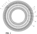
- FIG. 1 is a cross-sectional view showing a basic structure of a permanent magnet-type rotary electric machine disclosed in the present invention. The operation of the permanent magnetic-type rotary electric machine when used as a generator is described first using FIG. 1 . Note that the rotary electric machine is described taking a generator as an example in the present invention, but can also be applied to a case used as an electric motor.
- a stator 1 includes a stator core 2 having a plurality of stator slots 3 formed therein, and stator coils 4 are accommodated in the stator slots 3.
- the stator coils 4 are wound on the stator teeth 5 in a concentrated winding manner.
- Stator magnets 6 that are permanent magnets are accommodated in the stator slots 3, and all stator magnets 6 are magnetized to have the same pole of polarity in the radial direction.
- the stator magnets 6 are N poles
- the stator teeth 5 are S poles; N S pole pairs that are the same as the number of stator slots 3 are formed.
- a first rotor 10 is disposed facing the stator 1 across an air gap and made up of a plurality of pole pieces 11 arranged circumferentially. The number of pole pieces is expressed as N L .
- a second rotor 20 is disposed facing the first rotor 10 across an air gap. The second rotor 20 has second rotor magnets (permanent magnets) 21 and forms N H pole pairs (the number of poles is 2 ⁇ N H ) .
- the permanent magnet-type rotary electric machine disclosed in the present invention is referred to as permanent magnet-type rotary electric machine having a magnetic transmission mechanism.
- the induced voltage generated in the stator coils 4 at no load needs to be increased.
- a method of increasing the amount of linkage of magnetic flux generated from the second rotor magnets 21 with the stator coils 4 and increasing the frequency of the magnetic flux linking with the stator coils 4 are effective.
- the input i.e., the torque generated in the first rotor 10 needs to be increased.
- the torque generated in the first rotor 10 is almost independent of the current through the stator coils 4 but is generated by interaction of the magnetic flux from the stator magnets 6 and the magnetic flux from the second rotor magnets 21 with the pole pieces 11 of the first rotor 10.
- the size of the rotary electric machine or the volume of permanent magnets to be used that is necessary for such the permanent magnet-type rotary electric machine to obtain an output is determined by influence of both the magnitude of induced voltage and the magnitude of torque.
- a rotary electric machine having a smaller size is excellent and a smaller volume of permanent magnets to be used is also excellent from the aspect of global environmental protection.
- the size of the rotary electric machine or the volume of permanent magnets to be used depends more significantly on the magnitude of torque than on the magnitude of induced voltage. That is, by increasing the torque, the size of the rotary electric machine of the present invention is reduced and the volume of permanent magnets to be used can be reduced.
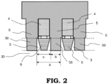
- FIG. 2 is an enlarged conceptual view showing a cross-section near the stator teeth of the permanent magnet-type rotary electric machine according to Embodiment 1.
- FIG. 2 shows a portion including two of the stator slots 3.
- the stator coils 4 are accommodated in the stator slots 3 and wound on the stator teeth 5 in the concentrated winding manner.
- the stator magnets 6 are accommodated in the stator slots 3, and all stator magnets 6 in the respective slots are magnetized to have the same pole of polarity in the radial direction.
- the stator magnets 6 are arranged in the stator slots 3 nearer the first air gap 30 than the stator coils 4.
- stator teeth 50 that are portions of the stator teeth 5 corresponding to portions where the stator magnets 6 are arranged, i.e., positioned between the respective stator magnets 6 accommodated in the adjacent stator slots 3 (positioned between the adjacent stator magnets 6 ) as shown in FIG. 2 .
- the circumferential width of the stator teeth 50 positioned between the adjacent stator magnets 6 is expressed as b , the pitch of the stator teeth 5 at the portion facing the first air gap 30, i.e., at the air gap surface, as a , and the circumferential width of the stator slots 3, as c . It is noted that in Embodiment 1, all of the stator teeth 50 positioned between the adjacent stator magnets 6 have the same circumferential width.
- the b / a ⁇ 100 [%] is set to 50 % or less in Embodiment 1, i.e., the circumferential width of the stator teeth 50 positioned between the adjacent stator magnets 6 is set narrower than the circumferential width c of the stator slots.
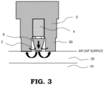
- FIG. 3 is a diagram schematically showing magnetic flux generated from the stator magnets 6 magnetized in the direction of the straight arrow. Magnetic flux generated from the stator magnets 6 that reaches the pole pieces 11 of the first rotor 10 through the first air gap 30 is effective magnetic flux contributing to the torque.
- magnetic flux generated from the stator magnets 6 reaching the stator teeth 5 through the circumferentially neighboring spaces as shown by the thin curved arrows in the figure is leakage magnetic flux not contributing to the torque.
- magnetic flux generated from the stator magnets 6 leaks to the stator teeth 5 as shown by the thick curved arrows before reaches the pole pieces 11 of the rotor 10.
- the first rotor 10 is the structure having the plurality of pole pieces 11, the permeance coefficient of the stator magnets 6 tends to be low compared to a general permanent magnet-type rotary electric machine.
- stator teeth 5 having a narrower width increases effective magnetic flux contributing to the torque.
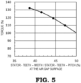
- FIG. 5 is a line graph showing the analysis results with varying the width of the stator teeth and with the same stator magnets 6 by setting to 100 % the torque in a case of the stator-teeth-width/stator-teeth-pitch being 50 %.
- FIG. 6 is an enlarged conceptual view showing a cross-sectional view near the stator teeth of the permanent magnet-type rotary electric machine according to Embodiment 2.
- the stator coils 4 are accommodated in the stator slots 3 and wound on the stator teeth 5 in the concentrated winding manner.
- the stator magnets 6 are accommodated in the stator slots 3 and all stator magnets 6 in the slots are magnetized to have the same pole of polarity in the radial direction.
- the stator magnets 6 are arranged nearer the first air gap 30 than the stator coils 4.
- Embodiment 1 it was shown that the torque is improved by narrowing the width of the stator teeth more than the width of the stator slots.
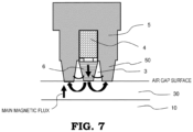
- FIG. 7 magnetic flux generated from the stator magnets that passes in the stator teeth 50 positioned between the adjacent stator magnets 6 is superimposes on the magnetic flux (main magnetic flux) from the second rotor magnets 21.
- stator teeth 50 positioned between the adjacent stator magnets 6 are likely to cause magnetic saturation, thus posing a problem in that the narrower the width of the stator teeth (the wider the width of the stator slots), the more decreases the induced voltage obtained by linkage of the magnetic flux from the second rotor 20 with the stator coils due to the magnetic saturation in the stator teeth 5.
- tapeering in width the stator teeth 50 positioned between the adjacent stator magnets 6 toward the air gap as a configuration for mitigating the magnetic flux saturation in the stator teeth 50 positioned between the adjacent stator magnets 6 and for reducing leakage of the magnetic flux from the stator magnets 6 allows for increasing the cross-sectional area of the stator teeth 5 at the opposite side of the air gaps (near the stator coils), of the stator magnets 6, thereby being able to mitigate the magnetic saturation.
- the leakage magnetic flux can be reduced while mitigating decrease of the induced voltage, whereby the torque can be increased.
- FIG. 8 shows the torque in a case of varying the stator teeth width at the air gap surface, with the width at the position nearest the stator coils 4, of the stator teeth among the width of the stator teeth 50 positioned between the adjacent the stator magnets being fixed to 44.5 % of the stator teeth pitch and with the same stator magnets 6.
- FIG. 8 is shown by setting to 100 % the torque in the case of the width throughout the radial direction of the stator teeth 50 positioned between the adjacent stator magnets being 44.5 % of the stator teeth pitch. It can be seen from the same figure that the torque is improved while mitigating influence of magnetic saturation in the stator teeth as much as possible.
- stator slot width between the stator teeth 50 positioned between the adjacent stator magnets improves the torque, thus being able to reduce the volume of permanent magnets to be used and the machine size.
- the circumferential width at the nearest (the outermost circumference of) the stator coils 4, of the stator teeth 50 positioned between the adjacent stator magnets is preferably, but not limited to, narrower than the circumferential width at the same radial position, of the stator slots, i.e., less than 50 % of the stator teeth pitch.
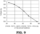
- FIG. 9 in a case of varying the stator teeth width at the air gap surface, with the width at the position nearest the stator coils 4, of the stator teeth among the width of the stator teeth 50 positioned between the adjacent the stator magnets being fixed to 57.7 % of the stator teeth pitch and with the same stator magnets 6.
- FIG. 9 is shown by setting to 100 % the torque in the case of the width throughout the radial direction of the stator teeth 50 positioned between the adjacent stator magnets being 57.7 % of the stator teeth pitch.
- stator-teeth circumferential width at the position nearest the stator coils 4 among the positions between the adjacent stator magnets is 50 % or more of the stator pitch (in other words, although the circumferential width nearest the stator coils 4, of the stator teeth 50 positioned between the stator magnets is wider than the stator-slot circumferential width at the same radial position), the same effect is brought about.
- the stator magnets 6 are formed to have a width so as to be away from the stator teeth toward the air gaps, in other words, the stator magnets 6 are shaped tapered in circumferential width toward the inner circumference, whereby the distance between the stator magnets 6 and the stator teeth 50 positioned between the adjacent stator magnets can be further increased, thus improving the torque.
Landscapes
- Engineering & Computer Science (AREA)
- Power Engineering (AREA)
- Permanent Field Magnets Of Synchronous Machinery (AREA)
- Permanent Magnet Type Synchronous Machine (AREA)
Abstract
Description
- The present invention relates to a permanent magnet-type rotary electric machine.
- There has been a rotary electric machine that is capable of changing the rotation speed of the rotor with the stator and the rotors being in no contact with each other. For example, such a rotary electric machine that is a magnetic wave gear machine is disclosed in Patent Document 1. The magnetic wave gear machine disclosed in Patent Document 1 includes a stator, a first rotor that rotates at a low speed, and a second rotor that rotates at a high speed depending on a speed change ratio. The stator, the first rotor, and the second rotor are disposed about the rotation axis in this order from the outer circumference. The stator is provided with stator coils. The stator coils are for outputting generated electric power or for controlling generated torque.
- According to the magnetic wave gear machine disclosed in Patent Document 1, since the speed of the second rotor can be changed with the first rotor and the second rotor being in no contact with the stator, a mechanical transmission is eliminated and maintenance loads for coping with mechanical wear and the like can be mitigated.
-
- Patent Document 1:
JP2016-135014A - Patent Document 2:
WO2020-174936A - The rotary electric machine disclosed in Patent Document 1 has a plurality of stator slots in the stator, and the stator coils and stator magnets (permanent magnets) are accommodated in the respective stator slots. The stator magnets in the respective stator slots are magnetized in the same direction. The first rotor having a plurality of pole pieces arranged circumferentially is disposed near the inner circumference of the stator, and the second rotor having permanent magnets is disposed near the inner circumference of the first rotor. Expressing the number of stator slots (= the number of stator teeth) of the stator as NS , the number of pole pieces of the first rotor as NL, and the number of pole pairs of the second rotor as NH, the following mathematical relationship is satisfied:

- In the rotary electric machine which is disclosed in Patent Document 1, however, the stator coils are wound on the stator in a distributed winding manner. Stator coils wound in a distributed winding manner, when the stator diameter is increased with increasing capacity, are reduced in workability. Hence, in a case of the capacity of the rotary electric machine being increased, workability of the stator coils is reduced.
- On the other hand, in a case of the stator coils wound in a concentrated winding manner, although the capacity is increased, reduction in workability of the stator coils is suppressed. For this reason, in order to suppress the reduction in workability of the stator coils, the stator coils of the rotary electric machine are preferably wound in a concentrated winding manner.
- In a case of operating as a generator the rotary electric machine disclosed in Patent Document 1, when the first rotor is rotated by an external power, the magnetic force of the stator magnets and the magnetic force of the second rotor magnets are modulated by the plurality of pole pieces of the first rotor, whereby the second rotor is rotated at an increased speed.
- Linkage of magnetic force generated from the permanent magnets of the second rotor increased in speed with the stator coils induces a generated power in the stator coils. That is, increasing the rotation speed of the second rotor or linking more magnetic force of the permanent magnets of the second rotor with the stator coils by narrowing the air gaps from the second rotor to the stator increases induced voltage and results in increase of the generated power.
- Input is generated by rotating the first rotor by an external power: (speed of the first rotor)×(torque acting on the first rotor). Since the torque is generated in the first rotor by modulation of the magnetic force from the stator magnets and the magnetic force from the permanent magnets of the second rotor by the pole pieces of the first rotor, in order to obtain a necessary output, the torque generated in the first rotor needs to be a predetermined value depending on the rotation speed. That is, by increasing the torque generated in the first rotor, the capacity can be increased.
- Generally, considering a generator of large capacity of megawatt-class reveals that the machine size or the amount of permanent magnets to be used is affected not by induced electromotive force (hereinafter, referred to as induced voltage) proportional to magnetic flux generated from the second rotor that links with the above-mentioned stator coils and to the rotation speed of the second rotor, but significantly by the magnitude of torque generated in the first rotor. In other words, although the induced voltage is increased, reduction of the torque leads to increase of the machine size or the amount of permanent magnets to be used.
- The magnetic geared motor disclosed in Patent Document 2 has the same structure as Patent Document 1, but the two circumferential right and left stator magnets accommodated in each of the stator slots are magnetized in the opposite directions. This allows the number NS of pole pairs formed by the stator magnets in each of the slots to be increased more than in a case of magnetizing in the same direction, and by configuring the first rotor to have an appropriate number of pole pieces, the ratio of speed increase/decrease is increased and the induced voltage is increased when used as a generator.
- However, compared with a configuration of magnetizing in the same direction the stator magnets in each of the slots, the magnetic force generated by one stator magnet of the same volume as the magnets is decreased, thus posing a problem of reducing the torque.
- The present invention has been made to resolve such the problem described above and is aimed at improving generated torque of a permanent magnet-type rotary electric machine that has stator coils configured in a concentrated winding manner and has stator magnets in the respective slots magnetized in the same direction.
- A permanent magnet-type rotary electric machine disclosed in the present invention comprises: a stator including: a stator core having a plurality of stator teeth formed in a circumferential direction; stator coils arranged on respective bottom sides of a plurality of stator slots formed between the stator teeth and wound on the stator teeth in a concentrated winding manner; and stator magnets having the same polarity in a radial direction and arranged on respective opening sides of the plurality of stator slots, a first rotor having a plurality of pole pieces and disposed coaxially with the stator to face the stator magnets; and a second rotor having a plurality of permanent magnets and disposed coaxially with the first rotor to face the first rotor, wherein the circumferential widths of the stator teeth positioned between the stator magnets arranged in adjacent stator slots among the plurality of stator slots are narrower than circumferential widths of the stator slots.
- The permanent magnet-type rotary electric machine according to the present invention has the stator coils configured in a concentrated winding manner and has stator magnets in the respective slots magnetized in the same direction, thus being able to improve the generated torque.
-
-
FIG. 1 is a cross-sectional view showing a whole basic structure of a permanent magnet-type rotary electric machine disclosed in the present invention; -
FIG. 2 is an enlarged conceptual view showing a cross-section near the stator teeth of the permanent magnet-type rotary electric machine according to Embodiment 1; -
FIG. 3 is a cross-sectional view schematically showing magnetic flux generated from the stator magnets of the permanent magnet-type rotary electric machine according to Embodiment 1; -
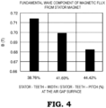
FIG. 4 is a graph showing results of analyzing the magnetic flux generated from the stator magnets of the permanent magnet-type rotary electric machine according to Embodiment 1; -
FIG. 5 is a line graph showing results of analyzing the torque of the permanent magnet-type rotary electric machine according to Embodiment 1; -
FIG. 6 is an enlarged conceptual view showing a cross-sectional view near the stator teeth of the permanent magnet-type rotary electric machine according to Embodiment 2; -
FIG. 7 is a cross-sectional view schematically showing magnetic flux generated from the stator magnets of the permanent magnet-type rotary electric machine according to Embodiment 2; -
FIG. 8 is a line graph showing results of analyzing the torque of the permanent magnet-type rotary electric machine according to Embodiment 2; and -
FIG. 9 is a line graph showing results of analyzing the torque of another configured permanent magnet-type rotary electric machine according to Embodiment 2. -
FIG. 1 is a cross-sectional view showing a basic structure of a permanent magnet-type rotary electric machine disclosed in the present invention. The operation of the permanent magnetic-type rotary electric machine when used as a generator is described first usingFIG. 1 . Note that the rotary electric machine is described taking a generator as an example in the present invention, but can also be applied to a case used as an electric motor. - Referring to
FIG. 1 , a stator 1 includes a stator core 2 having a plurality ofstator slots 3 formed therein, andstator coils 4 are accommodated in thestator slots 3. Thestator coils 4 are wound on thestator teeth 5 in a concentrated winding manner.Stator magnets 6 that are permanent magnets are accommodated in thestator slots 3, and allstator magnets 6 are magnetized to have the same pole of polarity in the radial direction. Hence, if thestator magnets 6 are N poles, thestator teeth 5 are S poles; NS pole pairs that are the same as the number ofstator slots 3 are formed. - A
first rotor 10 is disposed facing the stator 1 across an air gap and made up of a plurality ofpole pieces 11 arranged circumferentially. The number of pole pieces is expressed as NL. Asecond rotor 20 is disposed facing thefirst rotor 10 across an air gap. Thesecond rotor 20 has second rotor magnets (permanent magnets) 21 and forms NH pole pairs (the number of poles is 2× NH ). - In this case, if

first rotor 10 by magnetic interaction between thestator magnets 6 and thesecond rotor magnets 21, and rotating thefirst rotor 10 by an external power against the torque enables input to thefirst rotor 10 to be obtained. - If a stator current is passed through the
stator coils 4 against the input to thefirst rotor 10 for thesecond rotor 20 to run freely, thesecond rotor 20 rotates at a speed NL /NH times thefirst rotor 10. Since thesecond rotor 20 thus rotates at the speed NL /NH times thefirst rotor 10, the permanent magnet-type rotary electric machine disclosed in the present invention is referred to as permanent magnet-type rotary electric machine having a magnetic transmission mechanism. - When the
second rotor 20 rotates at the speed NL /NH times thefirst rotor 10, an induced electromotive force can be generated in thestator coils 4 by linkage of magnetic flux generated from thesecond rotor magnets 21 with thestator coils 4, and connecting this to a load enables a generated power to be output from thestator coils 4. - In order to increase the generated power output of the permanent magnet-type rotary electric machine having the magnetic transmission mechanism, it can be seen that the induced voltage generated in the
stator coils 4 at no load needs to be increased. In order to increase the induced voltage generated in the stator coils 4, it can be seen that a method of increasing the amount of linkage of magnetic flux generated from thesecond rotor magnets 21 with the stator coils 4 and increasing the frequency of the magnetic flux linking with the stator coils 4 are effective. - Regarding the former, methods are conceivable that increases the volume of second rotor magnets to be used, narrows two air gaps (a
first air gap 30 and asecond air gap 40 across the first rotor 10) between thesecond rotor 20 and the stator 1, and so on. Regarding the latter, a design is conceivable that increases the speed increase ratio ( NL / NH ). - However, in the permanent magnet-type rotary electric machine having such the magnetic transmission mechanism, in order to increase the output, the input, i.e., the torque generated in the
first rotor 10 needs to be increased. The torque generated in thefirst rotor 10 is almost independent of the current through the stator coils 4 but is generated by interaction of the magnetic flux from thestator magnets 6 and the magnetic flux from thesecond rotor magnets 21 with thepole pieces 11 of thefirst rotor 10. - Hence, the size of the rotary electric machine or the volume of permanent magnets to be used that is necessary for such the permanent magnet-type rotary electric machine to obtain an output is determined by influence of both the magnitude of induced voltage and the magnitude of torque. Of course, it goes without saying that a rotary electric machine having a smaller size is excellent and a smaller volume of permanent magnets to be used is also excellent from the aspect of global environmental protection.
- In the permanent magnet-type rotary electric machine disclosed in the present invention having the magnetic transmission mechanism, assuming a large capacity of megawatt-class output, it is found that the size of the rotary electric machine or the volume of permanent magnets to be used depends more significantly on the magnitude of torque than on the magnitude of induced voltage. That is, by increasing the torque, the size of the rotary electric machine of the present invention is reduced and the volume of permanent magnets to be used can be reduced.
-
FIG. 2 is an enlarged conceptual view showing a cross-section near the stator teeth of the permanent magnet-type rotary electric machine according to Embodiment 1.FIG. 2 shows a portion including two of thestator slots 3. The stator coils 4 are accommodated in thestator slots 3 and wound on thestator teeth 5 in the concentrated winding manner. Thestator magnets 6 are accommodated in thestator slots 3, and allstator magnets 6 in the respective slots are magnetized to have the same pole of polarity in the radial direction. Thestator magnets 6 are arranged in thestator slots 3 nearer thefirst air gap 30 than the stator coils 4. - A description is made below of a result of considering
stator teeth 50 that are portions of thestator teeth 5 corresponding to portions where thestator magnets 6 are arranged, i.e., positioned between therespective stator magnets 6 accommodated in the adjacent stator slots 3 (positioned between the adjacent stator magnets 6) as shown inFIG. 2 . - As shown in
FIG. 2 , the circumferential width of thestator teeth 50 positioned between theadjacent stator magnets 6 is expressed as b , the pitch of thestator teeth 5 at the portion facing thefirst air gap 30, i.e., at the air gap surface, as a , and the circumferential width of thestator slots 3, as c. It is noted that in Embodiment 1, all of thestator teeth 50 positioned between theadjacent stator magnets 6 have the same circumferential width. - Expressing as b / a ×100 [%] the ratio of the stator teeth width to the stator teeth pitch, the b / a ×100 [%] is set to 50 % or less in Embodiment 1, i.e., the circumferential width of the
stator teeth 50 positioned between theadjacent stator magnets 6 is set narrower than the circumferential width c of the stator slots. -
FIG. 3 is a diagram schematically showing magnetic flux generated from thestator magnets 6 magnetized in the direction of the straight arrow. Magnetic flux generated from thestator magnets 6 that reaches thepole pieces 11 of thefirst rotor 10 through thefirst air gap 30 is effective magnetic flux contributing to the torque. - However, in actuality magnetic flux generated from the
stator magnets 6 reaching thestator teeth 5 through the circumferentially neighboring spaces as shown by the thin curved arrows in the figure is leakage magnetic flux not contributing to the torque. Moreover, even in thefirst air gap 30, magnetic flux generated from thestator magnets 6 leaks to thestator teeth 5 as shown by the thick curved arrows before reaches thepole pieces 11 of therotor 10. - In such the permanent magnet-type rotary electric machine of the present invention having the magnetic transmission mechanism, since the
first rotor 10 is the structure having the plurality ofpole pieces 11, the permeance coefficient of thestator magnets 6 tends to be low compared to a general permanent magnet-type rotary electric machine. - That is, there is a problem in that a fairly amount of the magnetic flux generated from the
stator magnets 6 leaks to thestator teeth 5 through the paths as illustrated inFIG. 3 . This causes reduction of the torque. It can be seen that in order to reduce the leakage magnetic flux, it is desirable to widen the distance between thestator magnets 6 and thestator teeth 50 positioned between thestator magnets 6. - Results of an electromagnetic analysis of density of the magnetic flux from the
stator magnets 6 at the surface of thefirst air gap 30 of thefirst rotor 10 are shown inFIG. 4 with respect to the stator-teeth-width/stator-teeth-pitch at the air gap surface.FIG. 4 shows results of analyzing the fundamental wave component of the magnetic flux from the stator magnets. - The larger the magnetic flux of the fundamental wave component, the more the effective magnetic flux contributing the torque. It can be seen from
FIG. 4 that even though the volume of magnets is the same, thestator teeth 5 having a narrower width increases effective magnetic flux contributing to the torque. - Results of an electromagnetic analysis of the torque are shown in
FIG. 5 with respect to the stator-teeth-width/stator-teeth-pitch at the air gap surface of thestator teeth 5.FIG. 5 is a line graph showing the analysis results with varying the width of the stator teeth and with thesame stator magnets 6 by setting to 100 % the torque in a case of the stator-teeth-width/stator-teeth-pitch being 50 %. - It can be seen from the same figure that a narrower width of the
stator teeth 50 positioned between thestator magnets 6 improves the torque. In other words, by narrowing the width of thestator teeth 50 positioned between theadjacent stator magnets 6 more than the circumferential width of thestator slots 3, the torque can be improved with the same volume of permanent magnets used and the same machine size, thus being able to contribute to miniaturization of the machine. -
FIG. 6 is an enlarged conceptual view showing a cross-sectional view near the stator teeth of the permanent magnet-type rotary electric machine according to Embodiment 2. The stator coils 4 are accommodated in thestator slots 3 and wound on thestator teeth 5 in the concentrated winding manner. Thestator magnets 6 are accommodated in thestator slots 3 and allstator magnets 6 in the slots are magnetized to have the same pole of polarity in the radial direction. Thestator magnets 6 are arranged nearer thefirst air gap 30 than the stator coils 4. - The widths of the
stator slots 3 between thestator teeth 50 positioned between theadjacent stator magnets 6 gradually increase toward the air gaps, and the stator slot width at least at the air gap surface is narrower than the width of the slot openings. However, the circumferential width at the outermost circumference, i.e., near the bottoms of the stator slots, of thestator teeth 50 positioned between theadjacent stator magnets 6 is preferably narrower than the width of thestator slots 3 at the same radial position. - In the description of Embodiment 1, it was shown that the torque is improved by narrowing the width of the stator teeth more than the width of the stator slots. As shown in
FIG. 7 , magnetic flux generated from the stator magnets that passes in thestator teeth 50 positioned between theadjacent stator magnets 6 is superimposes on the magnetic flux (main magnetic flux) from thesecond rotor magnets 21. - For that reason, the
stator teeth 50 positioned between theadjacent stator magnets 6 are likely to cause magnetic saturation, thus posing a problem in that the narrower the width of the stator teeth (the wider the width of the stator slots), the more decreases the induced voltage obtained by linkage of the magnetic flux from thesecond rotor 20 with the stator coils due to the magnetic saturation in thestator teeth 5. - Tapering in width the
stator teeth 50 positioned between theadjacent stator magnets 6 toward the air gap as a configuration for mitigating the magnetic flux saturation in thestator teeth 50 positioned between theadjacent stator magnets 6 and for reducing leakage of the magnetic flux from thestator magnets 6 allows for increasing the cross-sectional area of thestator teeth 5 at the opposite side of the air gaps (near the stator coils), of thestator magnets 6, thereby being able to mitigate the magnetic saturation. Thus, the leakage magnetic flux can be reduced while mitigating decrease of the induced voltage, whereby the torque can be increased. - Results of the electromagnetic analysis for the
stator teeth 50 shaped tapered in width toward the inner circumference are shown inFIG. 8. FIG. 8 shows the torque in a case of varying the stator teeth width at the air gap surface, with the width at the position nearest the stator coils 4, of the stator teeth among the width of thestator teeth 50 positioned between the adjacent the stator magnets being fixed to 44.5 % of the stator teeth pitch and with thesame stator magnets 6. -
FIG. 8 is shown by setting to 100 % the torque in the case of the width throughout the radial direction of thestator teeth 50 positioned between the adjacent stator magnets being 44.5 % of the stator teeth pitch. It can be seen from the same figure that the torque is improved while mitigating influence of magnetic saturation in the stator teeth as much as possible. - In other words, it can be seen that widening gradually toward the air gap surface the stator slot width between the
stator teeth 50 positioned between the adjacent stator magnets improves the torque, thus being able to reduce the volume of permanent magnets to be used and the machine size. - The circumferential width at the nearest (the outermost circumference of) the stator coils 4, of the
stator teeth 50 positioned between the adjacent stator magnets is preferably, but not limited to, narrower than the circumferential width at the same radial position, of the stator slots, i.e., less than 50 % of the stator teeth pitch. Results of the electromagnetic analysis of the torque for thestator teeth 50 having the shape tapered in width toward the inner circumference are shown in -
FIG. 9 in a case of varying the stator teeth width at the air gap surface, with the width at the position nearest the stator coils 4, of the stator teeth among the width of thestator teeth 50 positioned between the adjacent the stator magnets being fixed to 57.7 % of the stator teeth pitch and with thesame stator magnets 6. -
FIG. 9 is shown by setting to 100 % the torque in the case of the width throughout the radial direction of thestator teeth 50 positioned between the adjacent stator magnets being 57.7 % of the stator teeth pitch. - It can be seen from the same figure that even though the stator-teeth circumferential width at the position nearest the stator coils 4 among the positions between the adjacent stator magnets is 50 % or more of the stator pitch (in other words, although the circumferential width nearest the stator coils 4, of the
stator teeth 50 positioned between the stator magnets is wider than the stator-slot circumferential width at the same radial position), the same effect is brought about. - As shown in
FIG. 2 andFIG. 6 , thestator magnets 6 are formed to have a width so as to be away from the stator teeth toward the air gaps, in other words, thestator magnets 6 are shaped tapered in circumferential width toward the inner circumference, whereby the distance between thestator magnets 6 and thestator teeth 50 positioned between the adjacent stator magnets can be further increased, thus improving the torque. - Although various exemplary embodiments and examples are described in the present invention, various features, aspects, and functions described in one or more embodiments are not inherent in a particular embodiment, and can be applicable alone or in their various combinations to each embodiment. Accordingly, countless variations that are not illustrated are envisaged within the scope of the art disclosed herein. For example, the case where at least one component is modified, added or omitted, and the case where at least one component is extracted and combined with a component in another embodiment are included.
-
- 1:
- stator
- 2:
- stator core
- 3:
- stator slots
- 4:
- stator coils
- 5:
- stator teeth
- 6:
- stator magnets
- 10:
- first rotor
- 11:
- pole pieces
- 20:
- second rotor
- 21:
- second rotor magnets (permanent magnets)
- 50:
- stator teeth positioned between adjacent stator magnets.
Claims (5)
- A permanent magnet-type rotary electric machine comprising:a stator including:a stator core having a plurality of stator teeth formed in a circumferential direction;stator coils arranged on respective bottom sides of a plurality of stator slots formed between the stator teeth and wound on the stator teeth in a concentrated winding manner; andstator magnets having the same polarity in a radial direction and arranged on respective opening sides of the plurality of stator slots,a first rotor having a plurality of pole pieces and disposed coaxially with the stator to face the stator magnets; anda second rotor having a plurality of permanent magnets and disposed coaxially with the first rotor to face the first rotor, wherein the circumferential widths of the stator teeth positioned between the stator magnets arranged in adjacent stator slots among the plurality of stator slots are narrower than the circumferential widths of the stator slots.
- A permanent magnet-type rotary electric machine comprising:a stator including:a stator core having a plurality of stator teeth formed in a circumferential direction;stator coils arranged on respective bottom sides of a plurality of stator slots formed between the stator teeth and wound on the stator teeth in a concentrated winding manner; andstator magnets having the same polarity in a radial direction and arranged on respective opening sides of the plurality of stator slots,a first rotor having a plurality of pole pieces and disposed coaxially with the stator to face the stator magnets; anda second rotor having a plurality of permanent magnets and disposed coaxially with the first rotor to face the first rotor, wherein at a position facing the first rotor, the circumferential widths of the stator teeth are narrower than the circumferential widths of the stator slots, andwherein the stator teeth positioned between the stator magnets arranged in adjacent stator slots among the plurality of the stator slots are tapered in circumferential width toward an inner circumference.
- The permanent magnet-type rotary electric machine of Claim 2, wherein a circumferential width at an outermost circumference, of the stator teeth positioned between the stator magnets is narrower than a circumferential width at the same radial position, of the stator slots.
- The permanent magnet-type rotary electric machine of any one of Claims 1 to 3,
wherein the stator magnets are tapered in circumferential width toward an inner circumference. - The permanent magnet-type rotary electric machine of any one of Claims 1 to 4,
wherein the number NS of stator slots of the stator, the number NL of pole pieces of the first rotor, and the number NH of pole pairs of the second rotor satisfy NL = NS + NH.
Applications Claiming Priority (1)
| Application Number | Priority Date | Filing Date | Title |
|---|---|---|---|
| PCT/JP2021/042377 WO2023089721A1 (en) | 2021-11-18 | 2021-11-18 | Permanent magnet-type rotary electric machine |
Publications (2)
| Publication Number | Publication Date |
|---|---|
| EP4436016A1 true EP4436016A1 (en) | 2024-09-25 |
| EP4436016A4 EP4436016A4 (en) | 2025-01-15 |
Family
ID=82155946
Family Applications (1)
| Application Number | Title | Priority Date | Filing Date |
|---|---|---|---|
| EP21964736.9A Pending EP4436016A4 (en) | 2021-11-18 | 2021-11-18 | Permanent magnet-type rotary electric machine |
Country Status (5)
| Country | Link |
|---|---|
| US (1) | US12620846B2 (en) |
| EP (1) | EP4436016A4 (en) |
| JP (1) | JP7090828B1 (en) |
| CN (1) | CN118216076A (en) |
| WO (1) | WO2023089721A1 (en) |
Families Citing this family (1)
| Publication number | Priority date | Publication date | Assignee | Title |
|---|---|---|---|---|
| JP7829446B2 (en) * | 2022-08-19 | 2026-03-13 | 三菱重工業株式会社 | Variable speed power unit and control method |
Family Cites Families (12)
| Publication number | Priority date | Publication date | Assignee | Title |
|---|---|---|---|---|
| FR2563059B1 (en) * | 1984-04-13 | 1988-04-15 | Cem Comp Electro Mec | VERNIER ELECTRODYNAMIC MACHINE |
| JP6093592B2 (en) * | 2013-02-22 | 2017-03-08 | 株式会社Ihi | Magnetic wave gear device |
| EP3147542B1 (en) * | 2014-05-20 | 2020-02-12 | IHI Corporation | Magnetic wave gear device |
| KR101669984B1 (en) * | 2014-09-03 | 2016-10-27 | 조선대학교산학협력단 | Salient-pole type magnetic gear |
| JP6403329B2 (en) | 2015-01-20 | 2018-10-10 | 株式会社Ihi | Magnetic wave gear device |
| US11979072B2 (en) | 2019-02-26 | 2024-05-07 | Panasonic Intellectual Property Management Co., Ltd. | Magnetic geared motor |
| DE102019133580A1 (en) | 2019-12-09 | 2021-06-10 | Bayerische Motoren Werke Aktiengesellschaft | Electrically excited synchronous machine with salient pole rotor and permanent magnetic leakage flux reduction |
| WO2021149130A1 (en) | 2020-01-21 | 2021-07-29 | 三菱電機株式会社 | Stator and rotating electric machine using same |
| EP4096070A4 (en) | 2020-01-21 | 2023-01-18 | Mitsubishi Electric Corporation | STATOR AND ROTATING ELECTRIC MACHINE USING IT |
| WO2021149129A1 (en) * | 2020-01-21 | 2021-07-29 | 三菱電機株式会社 | Stator and dynamo-electrical machine in which same is used |
| JP7384678B2 (en) * | 2020-01-24 | 2023-11-21 | 三菱重工業株式会社 | Magnetic geared rotating electric machine |
| JP7542184B2 (en) | 2020-03-23 | 2024-08-30 | パナソニックIpマネジメント株式会社 | Rotating Electric Machine |
-
2021
- 2021-11-18 JP JP2022520035A patent/JP7090828B1/en active Active
- 2021-11-18 CN CN202180104106.4A patent/CN118216076A/en not_active Withdrawn
- 2021-11-18 US US18/704,922 patent/US12620846B2/en active Active
- 2021-11-18 EP EP21964736.9A patent/EP4436016A4/en active Pending
- 2021-11-18 WO PCT/JP2021/042377 patent/WO2023089721A1/en not_active Ceased
Also Published As
| Publication number | Publication date |
|---|---|
| EP4436016A4 (en) | 2025-01-15 |
| US20240421643A1 (en) | 2024-12-19 |
| WO2023089721A1 (en) | 2023-05-25 |
| US12620846B2 (en) | 2026-05-05 |
| JP7090828B1 (en) | 2022-06-24 |
| JPWO2023089721A1 (en) | 2023-05-25 |
| CN118216076A (en) | 2024-06-18 |
Similar Documents
| Publication | Publication Date | Title |
|---|---|---|
| EP1990895B1 (en) | Stress distributing permanent magnet rotor geometry for electric machines | |
| JP6992368B2 (en) | Variable magnetic flux type permanent magnet type rotary electric machine | |
| US7804216B2 (en) | Permanent-magnet reluctance electrical rotary machine | |
| CN102263468B (en) | Rotary electric machine with improved magnetic resistance | |
| US9871420B2 (en) | Rotor for a rotary electric machine and rotary electric machine comprising such a rotor | |
| EP2595281A1 (en) | Rotating element with embedded permanent magnet and rotating electrical machine | |
| KR20140094516A (en) | Rotor for a rotating electric machine, and rotating electric machine comprising such a rotor | |
| JPWO2004064225A1 (en) | Permanent magnet type motor | |
| EP1598920A2 (en) | Permanent magnet rotary electric motor | |
| EP4080743B1 (en) | Magnetic geared rotary electric machine | |
| JP6212117B2 (en) | Synchronous motor | |
| CN103988400A (en) | Rotors for rotating electrical machines, and rotating electrical machines including rotors of this type | |
| JP6048191B2 (en) | Multi-gap rotating electric machine | |
| JP2007068357A (en) | Rotating electric machine rotor and rotating electric machine using the same | |
| JP4580683B2 (en) | Permanent magnet type reluctance type rotating electrical machine | |
| KR101473086B1 (en) | Rotary electric machine | |
| US12620846B2 (en) | Permanent magnet-type rotary electric machine | |
| CN113273057A (en) | Interior permanent magnet machine with flux distribution gap | |
| EP4293876A1 (en) | Magnetic geared rotary machine and power generation system | |
| CN117795825A (en) | Rotors and rotating electrical machines | |
| WO2019102580A1 (en) | Permanent magnet rotating electric machine | |
| US20230223805A1 (en) | Rotor and rotary electric machine | |
| EP4299951A1 (en) | Magnetic geared rotary machine, power generation system, and magnetic pole piece rotor | |
| JP2023071284A (en) | Permanent magnet electric motor | |
| WO2021182088A1 (en) | Permanent magnet synchronous motor |
Legal Events
| Date | Code | Title | Description |
|---|---|---|---|
| STAA | Information on the status of an ep patent application or granted ep patent |
Free format text: STATUS: THE INTERNATIONAL PUBLICATION HAS BEEN MADE |
|
| PUAI | Public reference made under article 153(3) epc to a published international application that has entered the european phase |
Free format text: ORIGINAL CODE: 0009012 |
|
| STAA | Information on the status of an ep patent application or granted ep patent |
Free format text: STATUS: REQUEST FOR EXAMINATION WAS MADE |
|
| 17P | Request for examination filed |
Effective date: 20240322 |
|
| AK | Designated contracting states |
Kind code of ref document: A1 Designated state(s): AL AT BE BG CH CY CZ DE DK EE ES FI FR GB GR HR HU IE IS IT LI LT LU LV MC MK MT NL NO PL PT RO RS SE SI SK SM TR |
|
| REG | Reference to a national code |
Ref country code: DE Ref legal event code: R079 Free format text: PREVIOUS MAIN CLASS: H02K0016020000 Ipc: H02K0003493000 |
|
| A4 | Supplementary search report drawn up and despatched |
Effective date: 20241218 |
|
| RIC1 | Information provided on ipc code assigned before grant |
Ipc: H02K 49/10 20060101ALN20241212BHEP Ipc: H02K 21/16 20060101ALN20241212BHEP Ipc: H02K 1/276 20220101ALI20241212BHEP Ipc: H02K 29/03 20060101ALI20241212BHEP Ipc: H02K 21/14 20060101ALI20241212BHEP Ipc: H02K 16/02 20060101ALI20241212BHEP Ipc: H02K 3/493 20060101AFI20241212BHEP |
|
| DAV | Request for validation of the european patent (deleted) | ||
| DAX | Request for extension of the european patent (deleted) |