EP4435930A2 - System, verfahren und computerprogrammprodukt zur erkennung des beginns des thermischen durchgehens mit einem ultraschallsensor - Google Patents
System, verfahren und computerprogrammprodukt zur erkennung des beginns des thermischen durchgehens mit einem ultraschallsensor Download PDFInfo
- Publication number
- EP4435930A2 EP4435930A2 EP24158957.1A EP24158957A EP4435930A2 EP 4435930 A2 EP4435930 A2 EP 4435930A2 EP 24158957 A EP24158957 A EP 24158957A EP 4435930 A2 EP4435930 A2 EP 4435930A2
- Authority
- EP
- European Patent Office
- Prior art keywords
- acoustic signal
- acoustic
- battery compartment
- flight
- time
- Prior art date
- Legal status (The legal status is an assumption and is not a legal conclusion. Google has not performed a legal analysis and makes no representation as to the accuracy of the status listed.)
- Pending
Links
Images



Classifications
-
- H—ELECTRICITY
- H01—ELECTRIC ELEMENTS
- H01M—PROCESSES OR MEANS, e.g. BATTERIES, FOR THE DIRECT CONVERSION OF CHEMICAL ENERGY INTO ELECTRICAL ENERGY
- H01M10/00—Secondary cells; Manufacture thereof
- H01M10/42—Methods or arrangements for servicing or maintenance of secondary cells or secondary half-cells
- H01M10/48—Accumulators combined with arrangements for measuring, testing or indicating the condition of cells, e.g. the level or density of the electrolyte
-
- G—PHYSICS
- G01—MEASURING; TESTING
- G01N—INVESTIGATING OR ANALYSING MATERIALS BY DETERMINING THEIR CHEMICAL OR PHYSICAL PROPERTIES
- G01N29/00—Investigating or analysing materials by the use of ultrasonic, sonic or infrasonic waves; Visualisation of the interior of objects by transmitting ultrasonic or sonic waves through the object
- G01N29/04—Analysing solids
- G01N29/07—Analysing solids by measuring propagation velocity or propagation time of acoustic waves
-
- G—PHYSICS
- G01—MEASURING; TESTING
- G01H—MEASUREMENT OF MECHANICAL VIBRATIONS OR ULTRASONIC, SONIC OR INFRASONIC WAVES
- G01H5/00—Measuring propagation velocity of ultrasonic, sonic or infrasonic waves, e.g. of pressure waves
-
- G—PHYSICS
- G01—MEASURING; TESTING
- G01N—INVESTIGATING OR ANALYSING MATERIALS BY DETERMINING THEIR CHEMICAL OR PHYSICAL PROPERTIES
- G01N29/00—Investigating or analysing materials by the use of ultrasonic, sonic or infrasonic waves; Visualisation of the interior of objects by transmitting ultrasonic or sonic waves through the object
- G01N29/04—Analysing solids
- G01N29/043—Analysing solids in the interior, e.g. by shear waves
-
- H—ELECTRICITY
- H01—ELECTRIC ELEMENTS
- H01M—PROCESSES OR MEANS, e.g. BATTERIES, FOR THE DIRECT CONVERSION OF CHEMICAL ENERGY INTO ELECTRICAL ENERGY
- H01M10/00—Secondary cells; Manufacture thereof
- H01M10/42—Methods or arrangements for servicing or maintenance of secondary cells or secondary half-cells
- H01M10/48—Accumulators combined with arrangements for measuring, testing or indicating the condition of cells, e.g. the level or density of the electrolyte
- H01M10/482—Accumulators combined with arrangements for measuring, testing or indicating the condition of cells, e.g. the level or density of the electrolyte for several batteries or cells simultaneously or sequentially
-
- G—PHYSICS
- G01—MEASURING; TESTING
- G01N—INVESTIGATING OR ANALYSING MATERIALS BY DETERMINING THEIR CHEMICAL OR PHYSICAL PROPERTIES
- G01N2291/00—Indexing codes associated with group G01N29/00
- G01N2291/01—Indexing codes associated with the measuring variable
- G01N2291/011—Velocity or travel time
-
- G—PHYSICS
- G01—MEASURING; TESTING
- G01N—INVESTIGATING OR ANALYSING MATERIALS BY DETERMINING THEIR CHEMICAL OR PHYSICAL PROPERTIES
- G01N2291/00—Indexing codes associated with group G01N29/00
- G01N2291/02—Indexing codes associated with the analysed material
- G01N2291/023—Solids
-
- G—PHYSICS
- G01—MEASURING; TESTING
- G01N—INVESTIGATING OR ANALYSING MATERIALS BY DETERMINING THEIR CHEMICAL OR PHYSICAL PROPERTIES
- G01N2291/00—Indexing codes associated with group G01N29/00
- G01N2291/10—Number of transducers
- G01N2291/102—Number of transducers one emitter, one receiver
-
- Y—GENERAL TAGGING OF NEW TECHNOLOGICAL DEVELOPMENTS; GENERAL TAGGING OF CROSS-SECTIONAL TECHNOLOGIES SPANNING OVER SEVERAL SECTIONS OF THE IPC; TECHNICAL SUBJECTS COVERED BY FORMER USPC CROSS-REFERENCE ART COLLECTIONS [XRACs] AND DIGESTS
- Y02—TECHNOLOGIES OR APPLICATIONS FOR MITIGATION OR ADAPTATION AGAINST CLIMATE CHANGE
- Y02E—REDUCTION OF GREENHOUSE GAS [GHG] EMISSIONS, RELATED TO ENERGY GENERATION, TRANSMISSION OR DISTRIBUTION
- Y02E60/00—Enabling technologies; Technologies with a potential or indirect contribution to GHG emissions mitigation
- Y02E60/10—Energy storage using batteries
Definitions
- Embodiments of the present disclosure relate generally to systems, methods, and computer program products for detecting thermal runaway in a battery pack, and more particularly, to detecting the onset of thermal runaway using an ultrasonic sensor placed within an internal battery compartment.
- Applicant has identified many technical challenges and difficulties associated with detecting the onset of thermal runaway in the early stages. Through applied effort, ingenuity, and innovation, Applicant has solved problems related to detecting the onset of thermal runaway, which are described in detail below.
- Various embodiments are directed to an example system, method, and computer program product for utilizing an ultrasonic sensor to detect the onset of thermal runaway in a battery pack.
- an example system for detecting a hazardous battery condition may comprise a battery case defining an internal battery compartment, the internal battery compartment comprising a battery cell.
- the example system may further comprise an acoustic transmitter disposed within the internal battery compartment and configured to transmit an acoustic signal.
- the example system may further comprise an acoustic receiver disposed within the internal battery compartment and positioned to receive the acoustic signal.
- the hazardous battery condition may be determined based on a change in a time of flight of the acoustic signal.
- the time of flight of the acoustic signal may be reduced due to the presence of an emitted gas from the battery cell in the internal battery compartment.
- the emitted gas may be hydrogen gas.
- the hazardous battery condition may be thermal runaway.
- the hazardous battery condition may be determined based on a rate of change of the time of flight of the acoustic signal.
- the hazardous battery condition may be determined in an instance in which the rate of change of the time of flight of the acoustic signal exceeds a pre-determined max rate of velocity change threshold.
- the system may further comprise a sensing device, wherein the sensing device is positioned within the internal battery compartment to measure a physical condition of the internal battery compartment, and wherein an expected time of flight of the acoustic signal is adjusted based on the physical condition of the internal battery compartment.
- the sensing device may comprise at least one of a temperature sensor and a humidity sensor.
- the acoustic signal may be an ultrasonic pulse.
- the acoustic transmitter may be positioned to transmit the acoustic signal at a reflecting wall of the internal battery compartment and the acoustic receiver may be positioned to receive the acoustic signal once it has reflected off one or more walls of the internal battery compartment.
- the system may further comprise a microcontroller configured to monitor the change in time of flight of the acoustic signal, electrically connected to the acoustic transmitter and the acoustic receiver.
- An example method for utilizing an acoustic signal to detect a hazardous battery condition may comprise causing an acoustic transmitter, disposed within an internal battery compartment of a battery case and comprising a battery cell, to transmit an acoustic signal.
- the example method may further comprise receiving, from an acoustic receiver disposed within the internal battery compartment, an electrical output representing the acoustic signal.
- the example method may comprise determining a time of flight of the acoustic signal.
- the example method may comprise determining the hazardous battery condition based on a change in the time of flight of the acoustic signal.
- the time of flight of the acoustic signal may be reduced due to the presence of an emitted gas from the battery cell in the internal battery compartment.
- the emitted gas may be hydrogen gas.
- the hazardous battery condition may be thermal runaway.
- the hazardous battery condition may be identified in an instance in which the rate of change of the time of flight of the acoustic signal exceeds a pre-determined max rate of velocity change threshold.
- the method may further comprise retrieving from a sensing device a measurement, indicating a physical condition of the internal battery compartment, and adjusting an expected time of flight of the acoustic signal based on the physical condition of the internal battery compartment.
- the sensing device may comprise at least one of a temperature sensor and a humidity sensor.
- the acoustic transmitter may be positioned to transmit the acoustic signal at a reflecting wall of the internal battery compartment and the acoustic receiver may be positioned to receive the acoustic signal once it has reflected off one or more walls of the internal battery compartment.
- the example computer program product may comprise at least one non-transitory computer-readable storage medium having computer-readable program code portions stored therein, the computer-readable program code portions comprising an executable portion configured to cause an acoustic transmitter, disposed within an internal battery compartment of a battery case and further comprising a battery cell, to transmit an acoustic signal.
- the computer-readable program code portions may comprise an executable portion further configured to receive, from an acoustic receiver disposed within the internal battery compartment, an electrical output representing the acoustic signal.
- the computer-readable program code portions may comprise an executable portion further configured to determine a time of flight of the acoustic signal. Further, in some embodiments, the computer-readable program code portions may comprise an executable portion further configured to determine the hazardous battery condition based on a change in the time of flight of the acoustic signal.
- Various example embodiments address technical problems associated with determining the onset of a thermal runaway event. As understood by those of skill in the field to which the present disclosure pertains, there are numerous scenarios in which it may be advantageous to detect thermal runaway in its early stages, providing opportunity to mitigate the hazardous condition before the thermal runaway becomes irreversible.
- batteries e.g., lithium-ion batteries, lithium-polymer batteries, etc.
- batteries may undergo a chemical reaction within a battery cell to supply power to various devices.
- Devices requiring substantial amounts of power, such as electric vehicles, may contain tens or even hundreds of battery cells in a battery pack.
- Battery cells utilizing chemical reactions to generate power may be susceptible to a number of hazardous conditions.
- One example hazardous battery cell condition that may result from various forms of stress and/or abuse is thermal runaway.
- the movement of electrons and lithium ions in the battery cell may produce heat faster than the battery pack can dissipate the generated heat.
- the temperature of the battery cell may rise uncontrollably until the battery cell combusts.
- thermal runaway can cause an uncontrollable rise in temperature in the battery cells commonly contained within a battery pack, causing neighboring battery cells to also enter into thermal runaway.
- a battery cell and/or battery pack may combust causing an extremely hazardous condition.
- a battery cell may progress through the stages of thermal runaway rapidly, providing little time to detect and mitigate the hazardous condition before the chain reaction is irreversible.
- the stress and abuse of the battery cells resulting in thermal runaway may be immediate and apparent.
- a battery cell on an electric vehicle may be punctured or ruptured by flying debris, leading to a thermal runaway event.
- long-term abuse of a battery cell or cells over an extended period of time may lead to thermal runaway.
- Overcharging, over-discharging, exposure to high and low temperatures, impacts to the battery pack, and/or physical damage to the battery cells may all affect the internal operation of the battery cells, especially when the abuse occurs over an extended period of time.
- mechanical abuse such as a crushing force on a battery cell may lead to an internal short circuit. A short circuit may in turn increase the internal heat in the battery cell triggering a thermal runaway condition.
- chronic overcharging and/or discharging may lead to plating and the formation of dendrites, which may subsequently cause short circuits.
- the chemical properties of the chemicals within the battery cell may slowly change over time due to mechanical, thermal, and electrical abuses. Due to the concealed nature of many of these factors, along with the long-term effects, and sudden onset of thermal runaway, it can be difficult to predict and/or detect a thermal runaway event before it is too late.
- Current battery management systems may utilize various sensors in close proximity to the battery cells to determine the condition of the battery cell based on the physical characteristics around the battery cell. For example, a temperature sensor may be placed on or near the surface of the battery cell. When the temperature measurement exceeds a pre-determined max operating temperature, the battery management system may issue a warning or alert. Similarly, a pressure sensor may be placed near the battery cells, configured to detect an increase in pressure within the battery pack. Once an increase in pressure or temperature is detected, the battery management system may issue an alert indicating the presence of the hazardous battery condition, such as thermal runaway.
- a temperature sensor may be placed on or near the surface of the battery cell. When the temperature measurement exceeds a pre-determined max operating temperature, the battery management system may issue a warning or alert.
- a pressure sensor may be placed near the battery cells, configured to detect an increase in pressure within the battery pack. Once an increase in pressure or temperature is detected, the battery management system may issue an alert indicating the presence of the hazardous battery condition, such as thermal runaway.
- these battery management systems do not issue warnings until the hazardous battery condition has progressed too far.
- temperature sensors outside of the battery cells may not detect an increase in temperature outside of the battery cells until after the interior temperature of the battery cell is already rising at an irreversible rate.
- an increase in pressure inside the battery pack may not be detected until after the battery cells have released internal gases and the temperature is rising uncontrollably.
- due to the chain-reaction nature of a thermal runaway event once the thermal runaway event has started, it cannot be stopped. As such, in some instances the battery cell will continue to overheat and eventually combust even after the condition is detected and the warning issued. Additionally, the overheating and combustion from a single battery cell may propagate to adjacent battery cells, in some instances leading to a battery pack explosion.
- the various example embodiments described herein utilize various techniques to detect thermal runaway in a battery pack in the early stages, while mitigating actions to stop the progression of thermal runaway may still be performed. For example, before a battery cell enters into the irreversible phase of thermal runaway, certain gases are emitted during the first venting stage. Among the emitted gases is hydrogen gas. One physical property of hydrogen gas is that it has a higher speed of sound compared to air at the same temperature and pressure. Thus, an acoustic signal will travel faster when hydrogen is present in an internal battery compartment than when there is only air in the internal battery compartment.
- the embodiments described herein enable a thermal runaway detection system to detect the presence of hydrogen gas during the first venting stage, enabling a battery management system to stop the progression of thermal runway before it is irreversible.
- the thermal runaway detection system may include an acoustic transmitter and an acoustic receiver placed within an internal battery compartment of the battery pack.
- the acoustic transmitter may periodically transmit an acoustic signal or chirp that is received by the acoustic receiver.
- the thermal runaway detection system may further include a processor or microcontroller configured to record the time the acoustic signal is transmitted by the acoustic transmitter and the time the acoustic signal is received by the acoustic receiver and thus determine the time of flight of the acoustic signal.
- the thermal runaway detection system may identify an increase in the speed of the acoustic signal within the internal battery compartment due to the presence of hydrogen gas.
- the presence of hydrogen gas in the internal battery compartment of a battery pack may be a key indicator of the onset of thermal runaway.
- a thermal runaway detection system as described herein may further include a temperature sensor within the internal battery compartment of a battery pack. By retrieving measurements from the temperature sensor, the thermal runaway detection system may distinguish changes in the speed of the acoustic signal due to a change in temperature. Further, the thermal runaway detection system may adjust the expected time of flight of the acoustic signal based on the temperature within the internal battery compartment of the battery pack.
- the thermal runaway detection system may identify the presence of hydrogen gas within the internal battery compartment of a battery pack based on the rate of change of the velocity, or the change in time of flight over time, of the acoustic signal.
- the speed of the acoustic signal may rapidly increase over a short period of time, before settling at a near constant increased speed.
- Such a change in speed over time may be detectable by a thermal runaway detection system.
- a thermal runaway detection system may monitor the rate of change of the velocity of the acoustic signal during operation.
- the thermal runaway detection system may determine that hydrogen gas is present in the internal battery compartment of the battery pack and the onset of thermal runaway has begun.
- the effectiveness of a thermal runaway detection system may be greatly improved.
- the speed with which the onset of thermal runaway is detected may be further enhanced, increasing the opportunity to mitigate the onset of thermal runaway before the hazardous condition becomes irreversible.
- the example thermal runaway progression 100 comprises three stages: off-gas generation stage 102, smoke generation stage 104, and fire generation stage 106.
- Each stage of the thermal runaway progression 100 is associated with a certain temperature or range of temperatures within the battery cell, as shown by the temperature scale 108.
- each stage of the thermal runaway progression 100 may be associated with a certain pressure or range of pressures within the battery compartment, as well as other characteristics such as the presence of certain gases.
- the off-gas generation stage 102 although the battery cell may be irreversibly damaged, the progression of thermal runaway can be stopped if mitigating actions are taken. Once a battery enters the smoke generation stage 104, the onset of thermal runaway is likely irreversible.
- the first stage of the example thermal runaway progression 100 is the off-gas generation stage 102.
- the off-gas generation stage 102 the electrolyte between the anode and cathode of the battery cell, begins to break down.
- the off-gas generation stage 102 is characterized by elevated gas levels, specifically elevated gas levels of oxygen and hydrogen.
- the operating temperature and the pressure readings initially remain constant, in a normal operating range for the battery cell and the environment during the off-gas generation stage 102.
- the operating temperature may be between 20°C and 80°C, while the pressure may remain below about 14.7 pounds per square inch.
- electrolyte between the anode and cathode within the battery cells fully breaks down.
- electrolyte vaporization may be characterized by a slight elevation in the internal pressure of the battery cell. The slight elevation in pressure may trigger the transfer of gas through the porous membranes of the one or more battery vents, equalizing the pressure within the battery compartment.
- Electrolyte vaporization may also be characterized by a slight increase in temperature, for example, between 80°C and 100°C and the presence of distinct gases, for example, elevated levels of Hydrogen (H 2 ), ethylene carbonate (EC), dimethyl carbonate (DMC), diethyl carbonate (DEC), and/or ethyl methyl carbonate (EMC).
- H 2 Hydrogen
- EC ethylene carbonate
- DMC dimethyl carbonate
- DEC diethyl carbonate
- EMC ethyl methyl carbonate
- the second stage of the example thermal runaway progression 100 is the smoke generation stage 104.
- the buildup of gas due to the decomposition of the electrolyte inside the battery cell may cause a drastic increase in the internal pressure of the interior battery compartment, leading to deformations in the casing of the battery cell and eventually the rupture of the porous membranes of the one or more battery vents disposed in the wall of the battery case.
- the rupture of the porous membrane may allow gases within the battery compartment to exit, alleviating some of the built up pressure within the battery compartment, at least momentarily.
- First venting may be characterized by an internal pressure in the internal battery compartment of a battery pack above 14.7 pounds per square inch, with rupture of the porous membrane, in some embodiments, occurring around 21 pounds per square inch.
- the smoke generation stage 104 may additionally be characterized by an initial increase in temperature, for example, between 120°C and 300°C along with elevated gas levels of H 2 , EC, DMC, DEC, EMC, and carbon dioxide.
- the smoke generation stage 104 catastrophic failure of the battery pack becomes imminent.
- chemical reactions within the battery cells continue due to a continued increase in temperature causing a severe and sudden increase of temperature.
- the chain reaction of chemical reactions and increased temperatures may spread to neighboring battery cells.
- the later portions of the smoke generation stage 104 as depicted in FIG. 1 may be characterized by the presence of smoke within the internal battery compartment and around the battery pack.
- the smoke generation stage 104 may be further characterized by continuing elevated gas levels of H 2 , EC, DMC, DEC, EMC, methane, carbon monoxide, ethanol, and carbon dioxide.
- the smoke generation stage 104 may be characterized by a temperature at or exceeding 300°C and less than 800°C.
- the final stage of the example thermal runaway progression is the fire generation stage 106.
- a battery may catch fire and/or explode creating an extremely hazardous situation.
- the temperature of the battery cell may exceed 800°C.
- the uncontrolled combustion during the fire generation stage 106 is extremely hazardous to the operating device and any people and objects in close proximity.
- the example thermal runaway detection system 200 includes a battery pack 204 defining an internal battery compartment 206, the internal battery compartment 206 containing a plurality of battery cells 202.
- an acoustic sensor 218 comprising an acoustic transmitter 210 and an acoustic receiver 214 are positioned within the internal battery compartment 206, such that a transmitted acoustic signal 212 transmitted by the acoustic transmitter 210 is received by the acoustic receiver 214 as a received acoustic signal 216.
- the internal battery compartment 206 includes one or more emitted gases 208 through which the transmitted acoustic signal 212 propagates.
- the example thermal runaway detection system 200 includes a battery pack 204 defining an internal battery compartment 206.
- a battery pack 204 may be any structure, packaging, housing, and/or compartment enclosing and/or protecting the plurality of battery cells 202.
- the battery pack 204 may further define a space or compartment (e.g., internal battery compartment 206) into which the internal battery components, such as the battery cells 202 and the acoustic sensor 218, may be disposed.
- the battery pack 204 may comprise aluminum, steel, or other metals; plastics and/or reinforced plastics; or any other material capable of protecting the interior components and one or more battery cells 202 of the thermal runaway detection system 200.
- the battery pack 204 may be manufactured to conform with an industry standard, such as IP67. In some embodiments, the battery pack 204 may provide structures to support, attach, and/or separate the battery cells 202, as well as wiring, and/or other internal components of the thermal runaway detection system 200.
- IP67 an industry standard
- the battery pack 204 may provide structures to support, attach, and/or separate the battery cells 202, as well as wiring, and/or other internal components of the thermal runaway detection system 200.
- Many electric vehicles today have begun arranging large numbers of battery cells 202 into a battery pack 204 that is integrated as part of the body of the electric vehicle. This technology has largely come to be known as cell-to-chassis technology. Such a battery arrangement may be particularly prone to thermal runaway and eventual combustion as a result of mechanical, electrical and/or thermal stress and abuse.
- the example battery pack 204 includes a plurality of battery enclosure walls (e.g., reflecting walls).
- the battery pack 204 may consist of one or more battery enclosure walls.
- the battery enclosure walls may comprise aluminum, steel, or other metals; plastics and/or reinforced plastics; or any other material capable of protecting the interior components and one or more battery cells 202.
- the acoustic transmitter 210 may generate a transmitted acoustic signal 212 directed at one or more of the battery enclosure walls.
- the battery enclosure walls may be configured to reflect the transmitted acoustic signal 212 toward an acoustic receiver 214.
- the battery enclosure walls may further provide attachment structures, cavities, openings, or other devices to attach sensing devices, battery vents, or other devices in support of the management of the thermal runaway detection system 200 and included components.
- the example thermal runaway detection system 200 includes a plurality of battery cells 202 within the internal battery compartment 206 of the battery pack 204. While depicted as a plurality of battery cells 202, the disclosure is not limited to a plurality of battery cells 202 as some embodiments may include a single battery cell.
- the battery cells 202 may take many forms, including but not limited to cylindrical cells, prismatic cells, pouch cells, etc.
- the battery cells 202 may be attached and/or separated by structures defined in the battery pack 204. Additionally, the battery cells 202 may be electrically connected in parallel and/or series to provide an accumulated power output to the operating device (e.g., an electric vehicle).
- Each battery cell 202 may house chemical components which undergo a chemical process to generate electrical current.
- the chemical components of the battery cells 202 may comprise numerous compositions, for example, lithium-ion, lithium-polymer, lithium-ion phosphate, lithium sulfur, and other lithium based compositions; nickel manganese cobalt; nickel metal hydride; lead acid; or any other chemical composition capable of providing sufficient electrical current through a chemical process.
- Devices requiring substantial amounts of power, such as electric vehicles may contain tens or even hundreds of battery cells 202 encased in a battery pack 204.
- the chemical reactions occurring in these battery cells 202 may be susceptible to dangerous battery conditions, such as thermal runaway.
- a battery cell 202 when a battery cell 202 experiences an increase in internal pressure due, for example, to a thermal runaway event, the battery cell 202 may release gases (e.g., emitted gases 208) into the surrounding environment (e.g., internal battery compartment 206). Internal pressure may build in a battery cell 202, due to a deteriorating separator layer, electrolyte degradation, increased heat due to a short circuit, and many other factors.
- a battery cell 202 may include a safety vent to release gases (e.g., emitted gases 208) if the internal pressure of the battery cell 202 exceeds a maximum internal pressure.
- Emitted gases 208 may include a variety of gases depending upon the cause for venting.
- Some emitted gases 208 may indicate that thermal runaway is or is about to occur, for example, the presence of hydrogen gas (H 2 ).
- An emitted gas 208 may be any gas released into the internal battery compartment 206 during the off-gas generation stage 102 of thermal runaway as explained in relation to FIG. 1 .
- Emitted gases 208 may include gases emitted due to chemical reactions occurring within the battery cell 202, gases released during the degradation of a battery cell 202 component, such as the separator layer, gases resulting from the evaporation of certain substances due to heat, etc.
- an emitted gas 208 may be an abnormal or elevated level of an otherwise common gas, such as oxygen or hydrogen.
- the emitted gases may contain a VOC, including, for example, dimethyl carbonate (DMC), diethyl carbonate (DEC), and/or ethyl methyl carbonate (EMC) methane.
- DMC dimethyl carbonate
- DEC diethyl carbonate
- EMC ethyl
- some emitted gases 208 may alter the speed of sound in the internal battery compartment 206.
- the presence of hydrogen gas (H 2 ) may increase the speed of sound in an environment, such as the internal battery compartment 206.
- hydrogen gas has a lower density than air, meaning the presence of hydrogen gas reduces the overall density of the air.
- the speed of sound in air increases when hydrogen gas is present as the sound waves can travel more easily through a less dense medium.
- the speed of sound in air at room temperature (20°C) and pressure (1 atmosphere) is 343 meters per second.
- the speed of sound in hydrogen gas at room temperature (20°C) and pressure (1 atmosphere) is 1,268 meters per second.
- the increased speed of sound results in a decreased time of flight of an acoustic signal across a fixed distance.
- the example thermal runaway detection system 200 includes an acoustic sensor 218 positioned in the internal battery compartment 206.
- An acoustic sensor 218 may be any electronic or electro-mechanical device capable of transmitting and/or receiving acoustic signals. Although depicted in FIG. 2 including an acoustic transmitter 210 and an acoustic receiver 214 in some embodiments an acoustic sensor 218 may comprise only an acoustic transmitter 210 or an acoustic receiver 214.
- the example thermal runaway detection system 200 includes an acoustic transmitter 210.
- An acoustic transmitter 210 may be any electronic or electro-mechanical device configured to transmit sound waves (e.g., transmitted acoustic signal 212).
- an acoustic transmitter 210 may generate sound waves utilizing a transducer to convert electrical energy into sound waves. The frequency of the generated sound wave may be dependent on the properties of the transducer, as well as the properties of the electrical energy provided to the transducer.
- the acoustic transmitter 210 may be configured to produce ultrasonic waves, for example, acoustic signals having a frequency above 20 kHz.
- Ultrasonic waves may enable highly accurate readings at high speeds, reducing the latency between off-gas generation and the determination of the onset of thermal runaway.
- an ultrasonic pulse or short ultrasonic transmission may be generated by the acoustic transmitter 210.
- the example thermal runaway detection system 200 includes an acoustic receiver 214.
- An acoustic receiver 214 may be any electronic or electro-mechanical device configured to receive sound waves (e.g., received acoustic signal 216) and convert the received sound wave into an analog or digital electric signal representing the sound wave an capable of being decoded.
- an acoustic receiver 214 may measure one or more physical characteristics of a received acoustic signal 216, such as the amplitude of the acoustic signal, the frequency of the acoustic signal, the wavelength, the time period, the velocity, or other similar physical characteristic.
- the received acoustic signal 216 in the internal battery compartment 206 may be used to determine an instance in which the battery cells 202 are experiencing venting, such as venting that occurs in the off-gas generation stage 102 of the thermal runaway progression 100.
- the received acoustic signal 216 may be a reflection of the transmitted acoustic signal 212 after reflecting off one or more walls of the battery pack 204.
- the received acoustic signal 216 may be received at the acoustic receiver 214 having a direct line of sight to the acoustic transmitter 210.
- a transmitted acoustic signal 212 may be reflected off one or more walls of the battery pack 204 to increase the distance between the acoustic signal (e.g., transmitted acoustic signal 212) transmitted by the acoustic transmitter 210.
- An increase in distance between the acoustic transmitter 210 and the acoustic receiver 214 may improve the accuracy of the acoustic sensor 218 when utilizing ultrasonic acoustic signals.
- a single acoustic receiver 214 is depicted in the example embodiment of FIG. 2 , a plurality of acoustic receivers 214 may be utilized as part of the thermal runaway detection system 200.
- the example thermal runaway detection system 300 includes a battery pack 204 defining an internal battery compartment 206, the internal battery compartment 206 containing a plurality of battery cells 202.
- an acoustic sensor 218 comprising an acoustic transmitter 210 and an acoustic receiver 214 are positioned within the internal battery compartment 206, such that a transmitted acoustic signal 212 transmitted by the acoustic transmitter 210 is received by the acoustic receiver 214 as a received acoustic signal 216.
- FIG. 3 the example thermal runaway detection system 300 includes a battery pack 204 defining an internal battery compartment 206, the internal battery compartment 206 containing a plurality of battery cells 202.
- an acoustic sensor 218 comprising an acoustic transmitter 210 and an acoustic receiver 214 are positioned within the internal battery compartment 206, such that a transmitted acoustic signal 212 transmitted by the acoustic transmitter 210 is received by the a
- the acoustic sensor 218 is communicatively connected to a controller 302.
- the controller 302 is further communicatively connected to a temperature sensor 304 and a warning device 306.
- the internal battery compartment 206 includes one or more emitted gases 208 through which the transmitted acoustic signal 212 propagates.
- the example thermal runaway detection system 300 includes a controller 302 (e.g., microcontroller).
- a controller 302 may be any means such as a processor, device, microcontroller, or circuitry embodied in either hardware or a combination of hardware and software that is configured to receive input data from each of the connected sensors (e.g., one or more acoustic sensors 218, one or more sensing devices, etc.), determine the time of flight of the acoustic signal (e.g., transmitted acoustic signal 212), determine whether a hazardous condition exists based on a change in the time of flight of the acoustic signal, and issue a warning via a warning device 306.
- the connected sensors e.g., one or more acoustic sensors 218, one or more sensing devices, etc.
- determine the time of flight of the acoustic signal e.g., transmitted acoustic signal 212
- the controller may further consider measurements recorded by one or more sensing devices (e.g., temperature sensor 304) when determining the existence of a hazardous condition.
- the controller 302 may comprise a form as shown and described in relation to FIG. 4 . While FIG. 4 provides an example controller 302, it is noted that the scope of the present disclosure is not limited to the example shown in FIG. 4 .
- the example thermal runaway detection system 300 further includes a temperature sensor 304.
- a temperature sensor 304 may be any electrical, mechanical, and/or electro-mechanical device configured to generate a signal representing the temperature of the atmosphere immediately surrounding the temperature sensor 304.
- the example temperature sensor 304 is disposed in the internal battery compartment 206 to monitor the temperature within the battery pack 204.
- the temperature in the internal battery compartment 206 may affect the speed of sound within the internal battery compartment 206. For example, the speed of sound in air at room temperature (20°C) and pressure (1 atmosphere) is 343 meters per second. In contrast, the speed of sound in air at freezing point (0°C) and pressure (1 atmosphere) is 331 meters per second.
- a pressure sensor may be utilized to determine the pressure within the internal battery compartment 206 and compensate for changes in time of flight of the transmitted acoustic signal 212 due to changes in temperature.
- a humidity sensor may be utilized to determine the humidity within the internal battery compartment 206 and compensate for changes in time of flight of the transmitted acoustic signal 212 due to changes in humidity.
- the example thermal runaway detection system 300 may include a warning device 306.
- the warning device 306 may be any device, hardware, software, or other mechanism to which a controller 302 may transmit a warning or alert indicating the onset of thermal runaway.
- a warning device 306 may provide any indication, warning, message, auditory or visible indicator, or other similar mechanism of the thermal runaway condition of the battery cells 202.
- warning device 306 may comprise a batter management system.
- the warning device e.g., battery management system
- the warning device may initiate a procedure to mitigate the hazardous condition, for example, disconnecting the load/charger and/or initiating measures to reduce the temperature of the battery cell or cells.
- the warning device 306 may transmit a message to a graphical user interface or another user facing mechanism alerting a user of the hazardous battery cell condition.
- the alert may prompt user action to mitigate the thermal runaway condition.
- a light or series of lights and/or sound or series of sounds may be utilized as an alerting mechanism for the underlying hazardous battery condition.
- FIG. 4 illustrates an example controller 302 in accordance with at least some example embodiments of the present disclosure.
- the controller 302 includes processor 402, input/output circuitry 404, data storage media 406, communications circuitry 408, acoustic sensor interface circuitry 410, sensing device interface circuitry 412, and warning device interface circuitry 414.
- the controller 302 is configured, using one or more of the sets of circuitry 402, 404, 406, 408, 410, 412, and/or 414, to execute and perform the operations described herein.
- circuitry as used herein with respect to components of the apparatuses described herein should therefore be understood to include particular hardware configured to perform the functions associated with the particular circuitry as described herein.
- circuitry should be understood broadly to include hardware and, in some embodiments, software for configuring the hardware.
- circuitry includes processing circuitry, storage media, network interfaces, input/output devices, and/or the like.
- other elements of the controller 302 provide or supplement the functionality of other particular sets of circuitry.
- the processor 402 in some embodiments provides processing functionality to any of the sets of circuitry
- the data storage media 406 provides storage functionality to any of the sets of circuitry
- the communications circuitry 408 provides network interface functionality to any of the sets of circuitry, and/or the like.
- the processor 402 (and/or co-processor or any other processing circuitry assisting or otherwise associated with the processor) is/are in communication with the data storage media 406 via a bus for passing information among components of the controller 302.
- the data storage media 406 is non-transitory and may include, for example, one or more volatile and/or non-volatile memories.
- the data storage media 406 in some embodiments includes or embodies an electronic storage device (e.g., a computer readable storage medium).
- the data storage media 406 is configured to store information, data, content, applications, instructions, or the like, for enabling the controller 302 to carry out various functions in accordance with example embodiments of the present disclosure.
- the processor 402 may be embodied in a number of different ways.
- the processor 402 includes one or more processing devices configured to perform independently.
- the processor 402 includes one or more processor(s) configured in tandem via a bus to enable independent execution of instructions, pipelining, and/or multithreading.
- the use of the terms "processor” and "processing circuitry” should be understood to include a single core processor, a multi-core processor, multiple processors internal to the controller 302, and/or one or more remote or “cloud” processor(s) external to the controller 302.
- the processor 402 is configured to execute instructions stored in the data storage media 406 or otherwise accessible to the processor.
- the processor 402 in some embodiments is configured to execute hard-coded functionality.
- the processor 402 represents an entity (e.g., physically embodied in circuitry) capable of performing operations according to an embodiment of the present disclosure while configured accordingly.
- the instructions specifically configure the processor 402 to perform the algorithms embodied in the specific operations described herein when such instructions are executed.
- the processor 402 is configured to perform various operations associated with utilizing an acoustic sensor to detect a hazardous battery condition.
- the processor 402 includes hardware, software, firmware, and/or a combination thereof, that causes an acoustic transmitter, disposed within an internal battery compartment of a battery case, to transmit an acoustic signal, wherein the internal battery compartment further comprises a battery cell.
- the processor 402 includes hardware, software, firmware, and/or a combination thereof, that receives, from an acoustic receiver disposed within the internal battery compartment, an electrical output representing the acoustic signal.
- the processor 402 includes hardware, software, firmware, and/or a combination thereof, that determines a time of flight of the acoustic signal. Additionally or alternatively, in some embodiments, the processor 402 includes hardware, software, firmware, and/or a combination thereof, that determines the hazardous battery condition based on a change in the time of flight of the acoustic signal.
- the controller 302 includes input/output circuitry 404 that provides output to the user and, in some embodiments, to receive an indication of a user input.
- the input/output circuitry 404 is in communication with the processor 402 to provide such functionality.
- the input/output circuitry 404 may comprise one or more user interface(s) (e.g., user interface) and in some embodiments includes a display that comprises the interface(s) rendered as a web user interface, an application user interface, a user device, a backend system, or the like.
- the processor 402 and/or input/output circuitry 404 comprising the processor may be configured to control one or more functions of one or more user interface elements through computer program instructions (e.g., software and/or firmware) stored on a memory accessible to the processor (e.g., data storage media 406, and/or the like).
- the input/output circuitry 404 includes or utilizes a user-facing application to provide input/output functionality to a client device and/or other display associated with a user.
- the controller 302 includes communications circuitry 408.
- the communications circuitry 408 includes any means such as a device or circuitry embodied in either hardware or a combination of hardware and software that is configured to receive and/or transmit data from/to a network and/or any other device, circuitry, or module in communication with the controller 302.
- the communications circuitry 408 includes, for example in some embodiments, a network interface for enabling communications with a wired or wireless communications network.
- the communications circuitry 408 includes one or more network interface card(s), antenna(s), bus(es), switch(es), router(s), modem(s), and supporting hardware, firmware, and/or software, or any other device suitable for enabling communications via one or more communications network(s). Additionally or alternatively, the communications circuitry 408 includes circuitry for interacting with the antenna(s) and/or other hardware or software to cause transmission of signals via the antenna(s) or to handle receipt of signals received via the antenna(s). In some embodiments, the communications circuitry 408 enables transmission to and/or receipt of data from a client device in communication with the controller 302.
- the acoustic sensor interface circuitry 410 includes hardware, software, firmware, and/or a combination thereof, that supports various functionality associated with configuring and communicating with an acoustic sensor (e.g., acoustic sensor 218).
- the acoustic sensor interface circuitry 410 includes hardware, software, firmware, and/or a combination thereof to communicate with the acoustic sensor according to an established protocol to provide appropriate configuration parameters to set and/or maintain the frequency and pattern of a transmitted acoustic signal (e.g., transmitted acoustic signal 212).
- the acoustic sensor interface circuitry 410 includes hardware, software, firmware, and/or a combination thereof, that decodes the received acoustic signal (e.g., received acoustic signal 216) to correlate the received acoustic signal with the transmitted acoustic signal and determine the time of flight of the acoustic signal.
- the acoustic sensor interface circuitry 410 includes a separate processor, specially configured field programmable gate array (FPGA), or a specially programmed application specific integrated circuit (ASIC).
- the sensing device interface circuitry 412 includes hardware, software, firmware, and/or a combination thereof, that supports various functionality associated with configuring a sensing device (e.g., temperature sensor 304).
- a sensing device e.g., temperature sensor 304
- the sensing device interface circuitry 412 includes hardware, software, firmware, and/or a combination thereof to communicate with the connected sensing device according to an established protocol to provide appropriate configuration parameters to receive data correlated with the temperature proximate the sensing device.
- the sensing device interface circuitry 412 includes hardware, software, firmware, and/or a combination thereof, that retrieves measurement data from the sensing device and decodes the retrieved data to determine the physical properties of the environment surrounding the sensing device.
- the sensing device interface circuitry 412 includes hardware, software, firmware, and/or a combination thereof, that configures the format and or frequency of the retrieved measurement data.
- the sensing device interface circuitry 412 includes a separate processor, specially configured field programmable gate array (FPGA), or a specially programmed application specific integrated circuit (ASIC).
- the warning device interface circuitry 414 includes hardware, software, firmware, and/or a combination thereof, that supports various functionality associated with configuring a warning device (e.g., warning device 306) to receive and perform actions based on the receipt of an alert or warning from the controller 302.
- a warning device e.g., warning device 306
- the warning device interface circuitry 414 includes hardware, software, firmware, and/or a combination thereof to communicate with the warning device according to an established protocol to provide appropriate configuration parameters to set output actions based on the warning/alert received.
- the warning device interface circuitry 414 includes a separate processor, specially configured field programmable gate array (FPGA), or a specially programmed application specific integrated circuit (ASIC).
- FPGA field programmable gate array
- ASIC application specific integrated circuit
- one or more of the sets of circuitry 402-414 are combinable. Additionally or alternatively, in some embodiments, one or more of the sets of circuitry perform some or all of the functionality described associated with another component. For example, in some embodiments, one or more sets of circuitry 402-414 are combined into a single module embodied in hardware, software, firmware, and/or a combination thereof. Similarly, in some embodiments, one or more of the sets of circuitry, for example acoustic sensor interface circuitry 410, sensing device interface circuitry 412, and/or warning device interface circuitry 414, is/are combined such that the processor 402 performs one or more of the operations described above with respect to each of these circuitry individually.
- a controller e.g., controller 302 causes an acoustic transmitter (e.g., acoustic transmitter 210), disposed within an internal battery compartment (e.g., internal battery compartment 206) of a battery case (e.g., battery pack 204), to transmit an acoustic signal (e.g., transmitted acoustic signal 212), wherein the internal battery compartment further comprises a battery cell (e.g., battery cell 202).
- the acoustic signal may be an ultrasonic signal, for example, having a frequency at or above 20 kilohertz.
- the acoustic signal may be generated having a distinguishable pattern such that the receipt of the acoustic signal may be correlated with the transmitted acoustic signal, for example, a short ultrasonic pulse.
- the transmitted acoustic signal may be directed at a wall of the battery pack such that the transmitted acoustic signal reflects off the wall before being received by an acoustic receiver.
- the controller receives, from an acoustic receiver (e.g., acoustic receiver 214) disposed within the internal battery compartment, an electrical output representing the acoustic signal.
- the acoustic receiver may be positioned to receive the received acoustic signal (e.g., received acoustic signal 216) from a direct line of sight transmission and/or after the transmitted acoustic signal has reflected off one or more walls of the battery pack.
- the acoustic receiver may further be configured to transmit the received acoustic signal via a communication connection to the processor.
- the transmitted acoustic signal may travel through one or more emitted gases (e.g., emitted gases 208) before being received by the acoustic receiver.
- emitted gases e.g., emitted gases 208
- the time of flight of the acoustic signal may have been altered from an expected time of flight.
- the controller determines a time of flight of the acoustic signal.
- the controller may record and/or otherwise store the time of transmission of the transmitted acoustic signal.
- the controller may determine the time of flight of the acoustic signal by determining the difference between the time the acoustic signal was received at the acoustic receiver and the stored time of transmission correlated with the transmission time of the transmitted acoustic signal.
- the controller may determine the hazardous battery condition based on a change in the time of flight of the acoustic signal.
- the change in time of flight of an acoustic signal may be an indicator of a hazardous battery condition.
- the presence of certain gases e.g., emitted gases 208 emitted from a battery cell during operation may be an indicator that the off-gas generation phase of thermal runaway has commenced.
- the speed of sound within the internal battery compartment may change. An increased speed of sound, for example due to the presence of hydrogen gas, may lead to a noticeable decrease in the time of flight of the transmitted acoustic signal.
- the controller may utilize other factors in determining if the change in time of flight of the acoustic signal is due to the presence of emitted gases indicating the onset of thermal runaway.
- a controller may retrieve from a sensing device (e.g., temperature sensor 304) a measurement, indicating a physical condition of the internal battery compartment, and adjust the change in the time of flight of the acoustic signal based on the measurement.
- the temperature, pressure, humidity, and other physical characteristics of the internal battery compartment may affect the time of flight of the acoustic signal. For example, in general, the acoustic signal travels slower in lower temperatures. However, in general, the acoustic signal travels faster in more humid environments.
- the controller may adjust the expected time of flight of the acoustic signal based on measurements such as temperature and humidity.
- the time of flight of the acoustic signal may be compared to the expected time of flight based on the physical conditions of the internal battery compartment.
- changes to the time of flight may be ignored or minimized in an instance in which it is determined that the changes are the result of a change in the physical condition of the internal battery compartment.
- a variety of methods may be utilized to detect a change in the time of flight of the acoustic signal and detect a hazardous battery condition, such as thermal runaway, based on the change in the time of flight. Some example embodiments are further depicted in FIG. 6 - FIG. 8 .
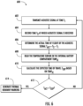
- an example process 600 for determining a change in the time of flight of an acoustic signal is provided.
- the controller e.g., controller 302 causes an acoustic signal to be transmitted by an acoustic transmitter (e.g., acoustic transmitter 210) and records the time the signal is transmitted as T 1 .
- the acoustic signal may be directed at a wall of the battery pack (e.g., battery pack 204) such that the acoustic signal travels from the acoustic transmitter, towards a wall of the battery pack and reflects off the wall of the battery pack before returning to the acoustic receiver.
- the acoustic signal may encounter one or more gases (e.g., emitted gases 208) present in the internal battery compartment of the battery pack.
- gases e.g., emitted gases 208
- the presence of one or more gases, particularly hydrogen gas may affect the speed of the acoustic signal as it travels through the internal battery compartment.
- the controller records the time at which the acoustic signal is received at an acoustic receiver (e.g., acoustic receiver 214) as time T 2 .
- the controller may correlate the received acoustic signal with the transmitted acoustic signal based on the frequency, shape, amplitude, and/or pattern of the received acoustic signal.
- the time the acoustic signal is received at the acoustic receiver may be recorded as time T 2 .
- the controller determines the actual time of flight ( T ACT ) of the acoustic signal by subtracting the transmission time ( T 1 ) from the time of reception of the acoustic signal ( T2 ).
- the controller reads the temperature sensor indicating the temperature of the internal battery compartment ( TEMP IC ) .
- measurements of the internal battery compartment may also be retrieved from various other sensing devices, for example, humidity sensors and pressure sensors.
- the processor calculates the expected time of flight ( T EXP ) .
- the expected time of flight is the time a sound signal is expected to travel between transmission from an acoustic transmitter and reception at an acoustic receiver.
- the expected time of flight may vary based on the physical dimensions of the battery compartment, the positions of the acoustic transmitter and acoustic receiver, the frequency of the transmitted signal, the physical conditions of the internal battery compartment, and so on.
- the expected time of flight may be the calculated time it would take a sound signal to travel from the acoustic transmitter, reflect off a reflecting wall of the battery pack, and return to the acoustic receiver, with no obstructions and at a given temperature.
- the expected time of flight may be adjusted based on the temperature in the internal battery compartment TEMP IC .
- the expected time of flight ( T EXP ) may be determined during a calibration of the thermal runaway detection system.
- the expected time of flight ( T EXP ) may depend on the acoustic sensor, the configuration of the transmitted acoustic signal, the physical dimensions of the battery pack, and other factors unique to each thermal runaway detection system.
- the expected time of flight ( T EXP ) may be recorded with an associated temperature.
- the actual time of flight ( T ACT ) of the acoustic signal is compared to the expected time of flight of the acoustic signal ( T EXP or T EXP_UPDATE ) .
- the controller may determine one or more battery cells are approaching thermal runaway and at step 614, the processor may generate a thermal runaway warning.
- the controller may determine that the battery cells are not entering into thermal runaway and the controller may return to step 602 to await transmission of another acoustic signal.
- a threshold or tolerance may be established allowing the actual time of flight to vary within that threshold or tolerance. For example, if the time of flight is 350 milliseconds, a threshold or tolerance of ⁇ 10 milliseconds may be established. Any variation of the time of flight within the threshold or tolerance may not indicate the onset of thermal runaway.
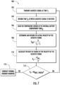
- an example process 700 for detecting thermal runaway based on a change in the time of flight of an acoustic signal is provided.
- the controller e.g., controller 302 causes an acoustic signal to be transmitted by an acoustic transmitter (e.g., acoustic transmitter 210) and records the time the signal is transmitted as T 1 .
- the acoustic signal may encounter one or more gases (e.g., emitted gases 208) present in the internal battery compartment of the battery pack.
- gases e.g., emitted gases 208
- the presence of one or more gases, particularly hydrogen gas may affect the speed of the acoustic signal as it travels through the internal battery compartment.
- the controller records the time at which the acoustic signal is received at an acoustic receiver (e.g., acoustic receiver 214) as time T 2 .
- the controller may correlate the received acoustic signal with the transmitted acoustic signal based on the frequency, shape, amplitude, and/or pattern of the received acoustic signal.
- the time the acoustic signal is received at the acoustic receiver may be recorded as time T 2 .
- the controller reads the temperature sensor indicating the temperature of the internal battery compartment ( TEMP IC ) .
- measurements indicating a physical condition of the internal battery compartment may also be retrieved from various other sensing devices, for example, humidity sensors and pressure sensors.
- step 708 depicts calculating the velocity of the acoustic receiver
- the present disclosure is not limited to calculating the velocity. Instead, in some embodiments, the time of flight of the acoustic signal may be determined and the rate of change of the time of flight may be used to detect the presence of an emitted gas in the internal battery compartment.
- the controller may record the actual velocity with an associated timestamp representing the time at which the actual velocity was recorded. By recording the actual velocity and associated time stamp, determinations regarding the rate of change of the velocity, or rate of change of the time of flight may be determined.
- the controller calculates the rate of change of the velocity of the acoustic signal ( R v ).
- FIG. 8 further depicts the relationship between the actual velocity of the acoustic signal and the rate of change of the velocity of the acoustic signal.
- step 710 depicts calculating a change in velocity of the acoustic receiver
- the present disclosure is not limited to calculating the change in velocity. Instead, in some embodiments, the change in the time of flight of the acoustic signal may be determined and the rate of change of the time of flight may be used to detect the presence of an emitted gas in the internal battery compartment.
- the rate of change of the velocity of the acoustic signal ( R v ) is compared to a pre-determined max rate of velocity change threshold ( RV max_Thresh ) .
- the pre-determined max rate of velocity change threshold represents the maximum allowable rate of change of the velocity of the acoustic signal, above which, the controller may determine the onset of thermal runaway has commenced.
- the change in velocity due to the presence of an emitted gas e.g., hydrogen gas
- the change in velocity may happen over a short period of time.
- the rate of change of the velocity of the acoustic signal may peak as the internal battery chamber begins to fill with the emitted gas.
- This peak in the rate of change of velocity may be detected by the controller, for example, if the rate of change of the velocity exceeds the pre-determined max rate of velocity change threshold.
- the controller may determine one or more battery cells are approaching thermal runaway and at step 714, the processor may generate a thermal runaway warning.
- the controller may determine that the battery cells are not entering into thermal runaway and the controller may return to step 702 to await transmission of another acoustic signal.
- step 712 depicts determining whether a rate of change of the velocity of the acoustic signal exceeds the pre-determined max rate of velocity change threshold
- the present disclosure is not limited to utilizing the rate of change of the velocity of the acoustic signal to detect the presence of an emitted gas in the internal battery compartment.
- the rate of change in the time of flight of the acoustic signal may be utilized to detect the presence of an emitted gas in the internal battery compartment.
- the controller may detect an instance in which the rate of change of the time of flight has dropped below a pre-determined minimum threshold.
- a graph 800 depicting an example relationship between the velocity of an acoustic signal (as represented by line 808) and the rate of change of the velocity of the acoustic signal (as represented by line 806).
- the axis 804 represents time
- the axis 802 represents velocity for line 808, for example, meters per second
- the axis 802 represents rate of change in velocity, for example, meters per second-squared for line 806.
- the velocity of the acoustic signal may increase a relatively small amount at time 812.
- the rate of change of the velocity of the acoustic signal may experience a noticeable peak.
- the controller may determine one or more battery cells have entered into the onset of thermal runaway.
Landscapes
- Physics & Mathematics (AREA)
- Chemical & Material Sciences (AREA)
- General Physics & Mathematics (AREA)
- Pathology (AREA)
- General Health & Medical Sciences (AREA)
- Immunology (AREA)
- Biochemistry (AREA)
- Acoustics & Sound (AREA)
- Health & Medical Sciences (AREA)
- Life Sciences & Earth Sciences (AREA)
- Analytical Chemistry (AREA)
- Chemical Kinetics & Catalysis (AREA)
- Electrochemistry (AREA)
- Manufacturing & Machinery (AREA)
- General Chemical & Material Sciences (AREA)
- Engineering & Computer Science (AREA)
- Secondary Cells (AREA)
- Investigating Or Analyzing Materials By The Use Of Ultrasonic Waves (AREA)
- Catching Or Destruction (AREA)
- Battery Mounting, Suspending (AREA)
Applications Claiming Priority (1)
| Application Number | Priority Date | Filing Date | Title |
|---|---|---|---|
| IN202311020377 | 2023-03-23 |
Publications (2)
| Publication Number | Publication Date |
|---|---|
| EP4435930A2 true EP4435930A2 (de) | 2024-09-25 |
| EP4435930A3 EP4435930A3 (de) | 2024-12-25 |
Family
ID=90038274
Family Applications (1)
| Application Number | Title | Priority Date | Filing Date |
|---|---|---|---|
| EP24158957.1A Pending EP4435930A3 (de) | 2023-03-23 | 2024-02-21 | System, verfahren und computerprogrammprodukt zur erkennung des beginns des thermischen durchgehens mit einem ultraschallsensor |
Country Status (2)
| Country | Link |
|---|---|
| US (1) | US20240319142A1 (de) |
| EP (1) | EP4435930A3 (de) |
Families Citing this family (2)
| Publication number | Priority date | Publication date | Assignee | Title |
|---|---|---|---|---|
| FR3166977A1 (fr) * | 2024-09-27 | 2026-04-03 | Vitruvens | Dispositif de surveillance d'un accumulateur électrique |
| CN119846477B (zh) * | 2025-01-22 | 2025-09-09 | 天津星日消防技术有限公司 | 一种基于线性判别分析的电池热失控状态监测评估方法 |
Family Cites Families (2)
| Publication number | Priority date | Publication date | Assignee | Title |
|---|---|---|---|---|
| SE544643C2 (en) * | 2019-11-08 | 2022-10-04 | Northvolt Ab | Arrangement and method for detecting malfunction in a battery |
| EP4330075A4 (de) * | 2021-04-30 | 2025-04-09 | Titan Advanced Energy Solutions, Inc. | Systeme, verfahren und vorrichtungen zur fehlererkennung einer oder mehrerer energiespeichervorrichtungen |
-
2024
- 2024-02-21 EP EP24158957.1A patent/EP4435930A3/de active Pending
- 2024-03-07 US US18/598,663 patent/US20240319142A1/en active Pending
Also Published As
| Publication number | Publication date |
|---|---|
| US20240319142A1 (en) | 2024-09-26 |
| EP4435930A3 (de) | 2024-12-25 |
Similar Documents
| Publication | Publication Date | Title |
|---|---|---|
| US20240319142A1 (en) | System, method, and computer program product for detecting the onset of thermal runaway using an ultrasonic sensor | |
| US20230124972A1 (en) | Thermal runaway detection system for batteries within enclosures | |
| EP4252865B1 (de) | Energiespeichersystem und steuerungsverfahren dafür | |
| JP6662319B2 (ja) | 異常検出装置 | |
| KR20230108259A (ko) | 인클로저 내의 배터리에 대한 열 폭주 검출 시스템 및 이의 사용 방법 | |
| EP3104447B1 (de) | Schadenserkennung und warnsystem eines batteriepacks | |
| US20250020729A1 (en) | Detection method and device for energy storage devices | |
| US20240295610A1 (en) | Methods and systems for safety monitoring of rechargeable lithium battery powering electrical device | |
| JP2012114078A (ja) | バッテリパックの安全性を判定する装置及び方法 | |
| JP2002289265A (ja) | リチウム二次電池の監視装置 | |
| CN108414943B (zh) | 电池检测装置、方法及电池包系统 | |
| US20210194070A1 (en) | Diagnosis of batteries | |
| JP2009059582A (ja) | 二次電池の圧力検出装置 | |
| US20250046894A1 (en) | Battery pack, electric apparatus, detection method of battery pack, and computer storage medium | |
| CN115117486A (zh) | 电池模块 | |
| US20240125867A1 (en) | Method, system, and apparatus for using a reference cell to monitor a battery cell condition | |
| US20240291055A1 (en) | Redundancy for battery protection | |
| KR102029210B1 (ko) | 노크센서를 이용한 차량용 배터리팩 손상검출장치 및 손상검출방법 | |
| EP4386934B1 (de) | System und verfahren zur erkennung von thermischem durchgehen mit akustischen und gassensoren | |
| CN116569438A (zh) | 用于外壳内的电池的热失控检测系统和其使用方法 | |
| WO2021089700A1 (en) | Arrangement and method for detecting malfunction in a battery | |
| EP4350838B1 (de) | Verfahren und vorrichtung zur verwendung der zeitsequenz von sensorereignissen zur bestimmung der ursache eines ereignisses zum thermischen durchgehen | |
| CN113686738B (zh) | 一种探测气溶胶特征的锂电池泄漏监测方法 | |
| GB2624307A (en) | Improvements in a cell assembly safety system | |
| CN113725501A (zh) | 具有早期识别系统的电池系统和用于进行早期识别的方法 |
Legal Events
| Date | Code | Title | Description |
|---|---|---|---|
| PUAI | Public reference made under article 153(3) epc to a published international application that has entered the european phase |
Free format text: ORIGINAL CODE: 0009012 |
|
| STAA | Information on the status of an ep patent application or granted ep patent |
Free format text: STATUS: REQUEST FOR EXAMINATION WAS MADE |
|
| 17P | Request for examination filed |
Effective date: 20240221 |
|
| AK | Designated contracting states |
Kind code of ref document: A2 Designated state(s): AL AT BE BG CH CY CZ DE DK EE ES FI FR GB GR HR HU IE IS IT LI LT LU LV MC ME MK MT NL NO PL PT RO RS SE SI SK SM TR |
|
| PUAL | Search report despatched |
Free format text: ORIGINAL CODE: 0009013 |
|
| AK | Designated contracting states |
Kind code of ref document: A3 Designated state(s): AL AT BE BG CH CY CZ DE DK EE ES FI FR GB GR HR HU IE IS IT LI LT LU LV MC ME MK MT NL NO PL PT RO RS SE SI SK SM TR |
|
| RIC1 | Information provided on ipc code assigned before grant |
Ipc: G01H 5/00 20060101ALI20241121BHEP Ipc: H01M 10/48 20060101AFI20241121BHEP |
|
| STAA | Information on the status of an ep patent application or granted ep patent |
Free format text: STATUS: EXAMINATION IS IN PROGRESS |
|
| 17Q | First examination report despatched |
Effective date: 20260119 |