EP4435365A1 - Verfahren und anlage zur tieftemperaturzerlegung von luft sowie verfahren und anlage zur herstellung von ammoniak - Google Patents
Verfahren und anlage zur tieftemperaturzerlegung von luft sowie verfahren und anlage zur herstellung von ammoniak Download PDFInfo
- Publication number
- EP4435365A1 EP4435365A1 EP23020152.7A EP23020152A EP4435365A1 EP 4435365 A1 EP4435365 A1 EP 4435365A1 EP 23020152 A EP23020152 A EP 23020152A EP 4435365 A1 EP4435365 A1 EP 4435365A1
- Authority
- EP
- European Patent Office
- Prior art keywords
- pressure column
- low
- column
- nitrogen
- production mode
- Prior art date
- Legal status (The legal status is an assumption and is not a legal conclusion. Google has not performed a legal analysis and makes no representation as to the accuracy of the status listed.)
- Withdrawn
Links
- 238000000926 separation method Methods 0.000 title claims abstract description 78
- QGZKDVFQNNGYKY-UHFFFAOYSA-N Ammonia Chemical compound N QGZKDVFQNNGYKY-UHFFFAOYSA-N 0.000 title claims abstract description 72
- 238000000034 method Methods 0.000 title claims abstract description 66
- 229910021529 ammonia Inorganic materials 0.000 title claims abstract description 36
- IJGRMHOSHXDMSA-UHFFFAOYSA-N Atomic nitrogen Chemical compound N#N IJGRMHOSHXDMSA-UHFFFAOYSA-N 0.000 claims abstract description 201
- 229910052757 nitrogen Inorganic materials 0.000 claims abstract description 101
- 238000004519 manufacturing process Methods 0.000 claims abstract description 98
- 239000007788 liquid Substances 0.000 claims abstract description 73
- 230000008569 process Effects 0.000 claims abstract description 55
- QVGXLLKOCUKJST-UHFFFAOYSA-N atomic oxygen Chemical compound [O] QVGXLLKOCUKJST-UHFFFAOYSA-N 0.000 claims abstract description 40
- 239000001301 oxygen Substances 0.000 claims abstract description 40
- 229910052760 oxygen Inorganic materials 0.000 claims abstract description 40
- 239000007789 gas Substances 0.000 claims abstract description 38
- XKRFYHLGVUSROY-UHFFFAOYSA-N Argon Chemical compound [Ar] XKRFYHLGVUSROY-UHFFFAOYSA-N 0.000 claims description 42
- 229910052739 hydrogen Inorganic materials 0.000 claims description 41
- 239000001257 hydrogen Substances 0.000 claims description 40
- UFHFLCQGNIYNRP-UHFFFAOYSA-N Hydrogen Chemical compound [H][H] UFHFLCQGNIYNRP-UHFFFAOYSA-N 0.000 claims description 39
- 229910052786 argon Inorganic materials 0.000 claims description 21
- 230000015572 biosynthetic process Effects 0.000 claims description 15
- 238000003786 synthesis reaction Methods 0.000 claims description 15
- CURLTUGMZLYLDI-UHFFFAOYSA-N Carbon dioxide Chemical compound O=C=O CURLTUGMZLYLDI-UHFFFAOYSA-N 0.000 claims description 10
- 239000012530 fluid Substances 0.000 claims description 9
- 238000001704 evaporation Methods 0.000 claims description 7
- 230000008020 evaporation Effects 0.000 claims description 7
- 238000002453 autothermal reforming Methods 0.000 claims description 6
- 229930195733 hydrocarbon Natural products 0.000 claims description 6
- 150000002430 hydrocarbons Chemical class 0.000 claims description 6
- 238000011084 recovery Methods 0.000 claims description 6
- 229910002092 carbon dioxide Inorganic materials 0.000 claims description 5
- 239000001569 carbon dioxide Substances 0.000 claims description 5
- 238000003860 storage Methods 0.000 claims description 5
- QJGQUHMNIGDVPM-UHFFFAOYSA-N nitrogen group Chemical group [N] QJGQUHMNIGDVPM-UHFFFAOYSA-N 0.000 claims description 4
- 239000004215 Carbon black (E152) Substances 0.000 claims description 2
- 239000000463 material Substances 0.000 description 8
- 238000007906 compression Methods 0.000 description 7
- 230000006835 compression Effects 0.000 description 6
- 238000001816 cooling Methods 0.000 description 5
- 238000010926 purge Methods 0.000 description 4
- OKTJSMMVPCPJKN-UHFFFAOYSA-N Carbon Chemical compound [C] OKTJSMMVPCPJKN-UHFFFAOYSA-N 0.000 description 3
- MYMOFIZGZYHOMD-UHFFFAOYSA-N Dioxygen Chemical compound O=O MYMOFIZGZYHOMD-UHFFFAOYSA-N 0.000 description 3
- 230000008901 benefit Effects 0.000 description 3
- 229910052799 carbon Inorganic materials 0.000 description 3
- XLYOFNOQVPJJNP-UHFFFAOYSA-N water Substances O XLYOFNOQVPJJNP-UHFFFAOYSA-N 0.000 description 3
- 238000006243 chemical reaction Methods 0.000 description 2
- 238000009833 condensation Methods 0.000 description 2
- 230000005494 condensation Effects 0.000 description 2
- 230000005611 electricity Effects 0.000 description 2
- 238000000605 extraction Methods 0.000 description 2
- 238000010438 heat treatment Methods 0.000 description 2
- 150000002431 hydrogen Chemical class 0.000 description 2
- 238000012856 packing Methods 0.000 description 2
- 239000007858 starting material Substances 0.000 description 2
- 238000001991 steam methane reforming Methods 0.000 description 2
- 239000000126 substance Substances 0.000 description 2
- 238000012546 transfer Methods 0.000 description 2
- 238000009825 accumulation Methods 0.000 description 1
- 230000003197 catalytic effect Effects 0.000 description 1
- 238000001833 catalytic reforming Methods 0.000 description 1
- 230000008859 change Effects 0.000 description 1
- 239000013064 chemical raw material Substances 0.000 description 1
- 238000005056 compaction Methods 0.000 description 1
- 239000012809 cooling fluid Substances 0.000 description 1
- 230000009849 deactivation Effects 0.000 description 1
- 238000000354 decomposition reaction Methods 0.000 description 1
- 230000001419 dependent effect Effects 0.000 description 1
- 230000000694 effects Effects 0.000 description 1
- 238000005868 electrolysis reaction Methods 0.000 description 1
- 238000005516 engineering process Methods 0.000 description 1
- 239000003337 fertilizer Substances 0.000 description 1
- 239000000446 fuel Substances 0.000 description 1
- 229910052743 krypton Inorganic materials 0.000 description 1
- DNNSSWSSYDEUBZ-UHFFFAOYSA-N krypton atom Chemical compound [Kr] DNNSSWSSYDEUBZ-UHFFFAOYSA-N 0.000 description 1
- 230000004048 modification Effects 0.000 description 1
- 238000012986 modification Methods 0.000 description 1
- DOTMOQHOJINYBL-UHFFFAOYSA-N molecular nitrogen;molecular oxygen Chemical compound N#N.O=O DOTMOQHOJINYBL-UHFFFAOYSA-N 0.000 description 1
- 229910052756 noble gas Inorganic materials 0.000 description 1
- 150000002835 noble gases Chemical class 0.000 description 1
- 230000003647 oxidation Effects 0.000 description 1
- 238000007254 oxidation reaction Methods 0.000 description 1
- 238000012545 processing Methods 0.000 description 1
- 239000002994 raw material Substances 0.000 description 1
- 229910052724 xenon Inorganic materials 0.000 description 1
- FHNFHKCVQCLJFQ-UHFFFAOYSA-N xenon atom Chemical compound [Xe] FHNFHKCVQCLJFQ-UHFFFAOYSA-N 0.000 description 1
Images




Classifications
-
- F—MECHANICAL ENGINEERING; LIGHTING; HEATING; WEAPONS; BLASTING
- F25—REFRIGERATION OR COOLING; COMBINED HEATING AND REFRIGERATION SYSTEMS; HEAT PUMP SYSTEMS; MANUFACTURE OR STORAGE OF ICE; LIQUEFACTION SOLIDIFICATION OF GASES
- F25J—LIQUEFACTION, SOLIDIFICATION OR SEPARATION OF GASES OR GASEOUS OR LIQUEFIED GASEOUS MIXTURES BY PRESSURE AND COLD TREATMENT OR BY BRINGING THEM INTO THE SUPERCRITICAL STATE
- F25J3/00—Processes or apparatus for separating the constituents of gaseous or liquefied gaseous mixtures involving the use of liquefaction or solidification
- F25J3/02—Processes or apparatus for separating the constituents of gaseous or liquefied gaseous mixtures involving the use of liquefaction or solidification by rectification, i.e. by continuous interchange of heat and material between a vapour stream and a liquid stream
- F25J3/04—Processes or apparatus for separating the constituents of gaseous or liquefied gaseous mixtures involving the use of liquefaction or solidification by rectification, i.e. by continuous interchange of heat and material between a vapour stream and a liquid stream for air
- F25J3/04006—Providing pressurised feed air or process streams within or from the air fractionation unit
- F25J3/04078—Providing pressurised feed air or process streams within or from the air fractionation unit providing pressurized products by liquid compression and vaporisation with cold recovery, i.e. so-called internal compression
- F25J3/0409—Providing pressurised feed air or process streams within or from the air fractionation unit providing pressurized products by liquid compression and vaporisation with cold recovery, i.e. so-called internal compression of oxygen
-
- F—MECHANICAL ENGINEERING; LIGHTING; HEATING; WEAPONS; BLASTING
- F25—REFRIGERATION OR COOLING; COMBINED HEATING AND REFRIGERATION SYSTEMS; HEAT PUMP SYSTEMS; MANUFACTURE OR STORAGE OF ICE; LIQUEFACTION SOLIDIFICATION OF GASES
- F25J—LIQUEFACTION, SOLIDIFICATION OR SEPARATION OF GASES OR GASEOUS OR LIQUEFIED GASEOUS MIXTURES BY PRESSURE AND COLD TREATMENT OR BY BRINGING THEM INTO THE SUPERCRITICAL STATE
- F25J3/00—Processes or apparatus for separating the constituents of gaseous or liquefied gaseous mixtures involving the use of liquefaction or solidification
- F25J3/02—Processes or apparatus for separating the constituents of gaseous or liquefied gaseous mixtures involving the use of liquefaction or solidification by rectification, i.e. by continuous interchange of heat and material between a vapour stream and a liquid stream
- F25J3/04—Processes or apparatus for separating the constituents of gaseous or liquefied gaseous mixtures involving the use of liquefaction or solidification by rectification, i.e. by continuous interchange of heat and material between a vapour stream and a liquid stream for air
- F25J3/04151—Purification and (pre-)cooling of the feed air; recuperative heat-exchange with product streams
- F25J3/04187—Cooling of the purified feed air by recuperative heat-exchange; Heat-exchange with product streams
- F25J3/04218—Parallel arrangement of the main heat exchange line in cores having different functions, e.g. in low pressure and high pressure cores
-
- F—MECHANICAL ENGINEERING; LIGHTING; HEATING; WEAPONS; BLASTING
- F25—REFRIGERATION OR COOLING; COMBINED HEATING AND REFRIGERATION SYSTEMS; HEAT PUMP SYSTEMS; MANUFACTURE OR STORAGE OF ICE; LIQUEFACTION SOLIDIFICATION OF GASES
- F25J—LIQUEFACTION, SOLIDIFICATION OR SEPARATION OF GASES OR GASEOUS OR LIQUEFIED GASEOUS MIXTURES BY PRESSURE AND COLD TREATMENT OR BY BRINGING THEM INTO THE SUPERCRITICAL STATE
- F25J3/00—Processes or apparatus for separating the constituents of gaseous or liquefied gaseous mixtures involving the use of liquefaction or solidification
- F25J3/02—Processes or apparatus for separating the constituents of gaseous or liquefied gaseous mixtures involving the use of liquefaction or solidification by rectification, i.e. by continuous interchange of heat and material between a vapour stream and a liquid stream
- F25J3/04—Processes or apparatus for separating the constituents of gaseous or liquefied gaseous mixtures involving the use of liquefaction or solidification by rectification, i.e. by continuous interchange of heat and material between a vapour stream and a liquid stream for air
- F25J3/04248—Generation of cold for compensating heat leaks or liquid production, e.g. by Joule-Thompson expansion
- F25J3/04284—Generation of cold for compensating heat leaks or liquid production, e.g. by Joule-Thompson expansion using internal refrigeration by open-loop gas work expansion, e.g. of intermediate or oxygen enriched (waste-)streams
-
- F—MECHANICAL ENGINEERING; LIGHTING; HEATING; WEAPONS; BLASTING
- F25—REFRIGERATION OR COOLING; COMBINED HEATING AND REFRIGERATION SYSTEMS; HEAT PUMP SYSTEMS; MANUFACTURE OR STORAGE OF ICE; LIQUEFACTION SOLIDIFICATION OF GASES
- F25J—LIQUEFACTION, SOLIDIFICATION OR SEPARATION OF GASES OR GASEOUS OR LIQUEFIED GASEOUS MIXTURES BY PRESSURE AND COLD TREATMENT OR BY BRINGING THEM INTO THE SUPERCRITICAL STATE
- F25J3/00—Processes or apparatus for separating the constituents of gaseous or liquefied gaseous mixtures involving the use of liquefaction or solidification
- F25J3/02—Processes or apparatus for separating the constituents of gaseous or liquefied gaseous mixtures involving the use of liquefaction or solidification by rectification, i.e. by continuous interchange of heat and material between a vapour stream and a liquid stream
- F25J3/04—Processes or apparatus for separating the constituents of gaseous or liquefied gaseous mixtures involving the use of liquefaction or solidification by rectification, i.e. by continuous interchange of heat and material between a vapour stream and a liquid stream for air
- F25J3/04248—Generation of cold for compensating heat leaks or liquid production, e.g. by Joule-Thompson expansion
- F25J3/04284—Generation of cold for compensating heat leaks or liquid production, e.g. by Joule-Thompson expansion using internal refrigeration by open-loop gas work expansion, e.g. of intermediate or oxygen enriched (waste-)streams
- F25J3/0429—Generation of cold for compensating heat leaks or liquid production, e.g. by Joule-Thompson expansion using internal refrigeration by open-loop gas work expansion, e.g. of intermediate or oxygen enriched (waste-)streams of feed air, e.g. used as waste or product air or expanded into an auxiliary column
- F25J3/04296—Claude expansion, i.e. expanded into the main or high pressure column
-
- F—MECHANICAL ENGINEERING; LIGHTING; HEATING; WEAPONS; BLASTING
- F25—REFRIGERATION OR COOLING; COMBINED HEATING AND REFRIGERATION SYSTEMS; HEAT PUMP SYSTEMS; MANUFACTURE OR STORAGE OF ICE; LIQUEFACTION SOLIDIFICATION OF GASES
- F25J—LIQUEFACTION, SOLIDIFICATION OR SEPARATION OF GASES OR GASEOUS OR LIQUEFIED GASEOUS MIXTURES BY PRESSURE AND COLD TREATMENT OR BY BRINGING THEM INTO THE SUPERCRITICAL STATE
- F25J3/00—Processes or apparatus for separating the constituents of gaseous or liquefied gaseous mixtures involving the use of liquefaction or solidification
- F25J3/02—Processes or apparatus for separating the constituents of gaseous or liquefied gaseous mixtures involving the use of liquefaction or solidification by rectification, i.e. by continuous interchange of heat and material between a vapour stream and a liquid stream
- F25J3/04—Processes or apparatus for separating the constituents of gaseous or liquefied gaseous mixtures involving the use of liquefaction or solidification by rectification, i.e. by continuous interchange of heat and material between a vapour stream and a liquid stream for air
- F25J3/04248—Generation of cold for compensating heat leaks or liquid production, e.g. by Joule-Thompson expansion
- F25J3/04375—Details relating to the work expansion, e.g. process parameter etc.
- F25J3/04387—Details relating to the work expansion, e.g. process parameter etc. using liquid or hydraulic turbine expansion
-
- F—MECHANICAL ENGINEERING; LIGHTING; HEATING; WEAPONS; BLASTING
- F25—REFRIGERATION OR COOLING; COMBINED HEATING AND REFRIGERATION SYSTEMS; HEAT PUMP SYSTEMS; MANUFACTURE OR STORAGE OF ICE; LIQUEFACTION SOLIDIFICATION OF GASES
- F25J—LIQUEFACTION, SOLIDIFICATION OR SEPARATION OF GASES OR GASEOUS OR LIQUEFIED GASEOUS MIXTURES BY PRESSURE AND COLD TREATMENT OR BY BRINGING THEM INTO THE SUPERCRITICAL STATE
- F25J3/00—Processes or apparatus for separating the constituents of gaseous or liquefied gaseous mixtures involving the use of liquefaction or solidification
- F25J3/02—Processes or apparatus for separating the constituents of gaseous or liquefied gaseous mixtures involving the use of liquefaction or solidification by rectification, i.e. by continuous interchange of heat and material between a vapour stream and a liquid stream
- F25J3/04—Processes or apparatus for separating the constituents of gaseous or liquefied gaseous mixtures involving the use of liquefaction or solidification by rectification, i.e. by continuous interchange of heat and material between a vapour stream and a liquid stream for air
- F25J3/044—Processes or apparatus for separating the constituents of gaseous or liquefied gaseous mixtures involving the use of liquefaction or solidification by rectification, i.e. by continuous interchange of heat and material between a vapour stream and a liquid stream for air using a single pressure main column system only
-
- F—MECHANICAL ENGINEERING; LIGHTING; HEATING; WEAPONS; BLASTING
- F25—REFRIGERATION OR COOLING; COMBINED HEATING AND REFRIGERATION SYSTEMS; HEAT PUMP SYSTEMS; MANUFACTURE OR STORAGE OF ICE; LIQUEFACTION SOLIDIFICATION OF GASES
- F25J—LIQUEFACTION, SOLIDIFICATION OR SEPARATION OF GASES OR GASEOUS OR LIQUEFIED GASEOUS MIXTURES BY PRESSURE AND COLD TREATMENT OR BY BRINGING THEM INTO THE SUPERCRITICAL STATE
- F25J3/00—Processes or apparatus for separating the constituents of gaseous or liquefied gaseous mixtures involving the use of liquefaction or solidification
- F25J3/02—Processes or apparatus for separating the constituents of gaseous or liquefied gaseous mixtures involving the use of liquefaction or solidification by rectification, i.e. by continuous interchange of heat and material between a vapour stream and a liquid stream
- F25J3/04—Processes or apparatus for separating the constituents of gaseous or liquefied gaseous mixtures involving the use of liquefaction or solidification by rectification, i.e. by continuous interchange of heat and material between a vapour stream and a liquid stream for air
- F25J3/04406—Processes or apparatus for separating the constituents of gaseous or liquefied gaseous mixtures involving the use of liquefaction or solidification by rectification, i.e. by continuous interchange of heat and material between a vapour stream and a liquid stream for air using a dual pressure main column system
- F25J3/04412—Processes or apparatus for separating the constituents of gaseous or liquefied gaseous mixtures involving the use of liquefaction or solidification by rectification, i.e. by continuous interchange of heat and material between a vapour stream and a liquid stream for air using a dual pressure main column system in a classical double column flowsheet, i.e. with thermal coupling by a main reboiler-condenser in the bottom of low pressure respectively top of high pressure column
-
- F—MECHANICAL ENGINEERING; LIGHTING; HEATING; WEAPONS; BLASTING
- F25—REFRIGERATION OR COOLING; COMBINED HEATING AND REFRIGERATION SYSTEMS; HEAT PUMP SYSTEMS; MANUFACTURE OR STORAGE OF ICE; LIQUEFACTION SOLIDIFICATION OF GASES
- F25J—LIQUEFACTION, SOLIDIFICATION OR SEPARATION OF GASES OR GASEOUS OR LIQUEFIED GASEOUS MIXTURES BY PRESSURE AND COLD TREATMENT OR BY BRINGING THEM INTO THE SUPERCRITICAL STATE
- F25J3/00—Processes or apparatus for separating the constituents of gaseous or liquefied gaseous mixtures involving the use of liquefaction or solidification
- F25J3/02—Processes or apparatus for separating the constituents of gaseous or liquefied gaseous mixtures involving the use of liquefaction or solidification by rectification, i.e. by continuous interchange of heat and material between a vapour stream and a liquid stream
- F25J3/04—Processes or apparatus for separating the constituents of gaseous or liquefied gaseous mixtures involving the use of liquefaction or solidification by rectification, i.e. by continuous interchange of heat and material between a vapour stream and a liquid stream for air
- F25J3/04406—Processes or apparatus for separating the constituents of gaseous or liquefied gaseous mixtures involving the use of liquefaction or solidification by rectification, i.e. by continuous interchange of heat and material between a vapour stream and a liquid stream for air using a dual pressure main column system
- F25J3/04424—Processes or apparatus for separating the constituents of gaseous or liquefied gaseous mixtures involving the use of liquefaction or solidification by rectification, i.e. by continuous interchange of heat and material between a vapour stream and a liquid stream for air using a dual pressure main column system without thermally coupled high and low pressure columns, i.e. a so-called split columns
-
- F—MECHANICAL ENGINEERING; LIGHTING; HEATING; WEAPONS; BLASTING
- F25—REFRIGERATION OR COOLING; COMBINED HEATING AND REFRIGERATION SYSTEMS; HEAT PUMP SYSTEMS; MANUFACTURE OR STORAGE OF ICE; LIQUEFACTION SOLIDIFICATION OF GASES
- F25J—LIQUEFACTION, SOLIDIFICATION OR SEPARATION OF GASES OR GASEOUS OR LIQUEFIED GASEOUS MIXTURES BY PRESSURE AND COLD TREATMENT OR BY BRINGING THEM INTO THE SUPERCRITICAL STATE
- F25J3/00—Processes or apparatus for separating the constituents of gaseous or liquefied gaseous mixtures involving the use of liquefaction or solidification
- F25J3/02—Processes or apparatus for separating the constituents of gaseous or liquefied gaseous mixtures involving the use of liquefaction or solidification by rectification, i.e. by continuous interchange of heat and material between a vapour stream and a liquid stream
- F25J3/04—Processes or apparatus for separating the constituents of gaseous or liquefied gaseous mixtures involving the use of liquefaction or solidification by rectification, i.e. by continuous interchange of heat and material between a vapour stream and a liquid stream for air
- F25J3/04436—Processes or apparatus for separating the constituents of gaseous or liquefied gaseous mixtures involving the use of liquefaction or solidification by rectification, i.e. by continuous interchange of heat and material between a vapour stream and a liquid stream for air using at least a triple pressure main column system
- F25J3/04442—Processes or apparatus for separating the constituents of gaseous or liquefied gaseous mixtures involving the use of liquefaction or solidification by rectification, i.e. by continuous interchange of heat and material between a vapour stream and a liquid stream for air using at least a triple pressure main column system in a double column flowsheet with a high pressure pre-rectifier
-
- F—MECHANICAL ENGINEERING; LIGHTING; HEATING; WEAPONS; BLASTING
- F25—REFRIGERATION OR COOLING; COMBINED HEATING AND REFRIGERATION SYSTEMS; HEAT PUMP SYSTEMS; MANUFACTURE OR STORAGE OF ICE; LIQUEFACTION SOLIDIFICATION OF GASES
- F25J—LIQUEFACTION, SOLIDIFICATION OR SEPARATION OF GASES OR GASEOUS OR LIQUEFIED GASEOUS MIXTURES BY PRESSURE AND COLD TREATMENT OR BY BRINGING THEM INTO THE SUPERCRITICAL STATE
- F25J3/00—Processes or apparatus for separating the constituents of gaseous or liquefied gaseous mixtures involving the use of liquefaction or solidification
- F25J3/02—Processes or apparatus for separating the constituents of gaseous or liquefied gaseous mixtures involving the use of liquefaction or solidification by rectification, i.e. by continuous interchange of heat and material between a vapour stream and a liquid stream
- F25J3/04—Processes or apparatus for separating the constituents of gaseous or liquefied gaseous mixtures involving the use of liquefaction or solidification by rectification, i.e. by continuous interchange of heat and material between a vapour stream and a liquid stream for air
- F25J3/04521—Coupling of the air fractionation unit to an air gas-consuming unit, so-called integrated processes
- F25J3/04527—Integration with an oxygen consuming unit, e.g. glass facility, waste incineration or oxygen based processes in general
- F25J3/04539—Integration with an oxygen consuming unit, e.g. glass facility, waste incineration or oxygen based processes in general for the H2/CO synthesis by partial oxidation or oxygen consuming reforming processes of fuels
-
- F—MECHANICAL ENGINEERING; LIGHTING; HEATING; WEAPONS; BLASTING
- F25—REFRIGERATION OR COOLING; COMBINED HEATING AND REFRIGERATION SYSTEMS; HEAT PUMP SYSTEMS; MANUFACTURE OR STORAGE OF ICE; LIQUEFACTION SOLIDIFICATION OF GASES
- F25J—LIQUEFACTION, SOLIDIFICATION OR SEPARATION OF GASES OR GASEOUS OR LIQUEFIED GASEOUS MIXTURES BY PRESSURE AND COLD TREATMENT OR BY BRINGING THEM INTO THE SUPERCRITICAL STATE
- F25J3/00—Processes or apparatus for separating the constituents of gaseous or liquefied gaseous mixtures involving the use of liquefaction or solidification
- F25J3/02—Processes or apparatus for separating the constituents of gaseous or liquefied gaseous mixtures involving the use of liquefaction or solidification by rectification, i.e. by continuous interchange of heat and material between a vapour stream and a liquid stream
- F25J3/04—Processes or apparatus for separating the constituents of gaseous or liquefied gaseous mixtures involving the use of liquefaction or solidification by rectification, i.e. by continuous interchange of heat and material between a vapour stream and a liquid stream for air
- F25J3/04521—Coupling of the air fractionation unit to an air gas-consuming unit, so-called integrated processes
- F25J3/04563—Integration with a nitrogen consuming unit, e.g. for purging, inerting, cooling or heating
- F25J3/04587—Integration with a nitrogen consuming unit, e.g. for purging, inerting, cooling or heating for the NH3 synthesis, e.g. for adjusting the H2/N2 ratio
-
- F—MECHANICAL ENGINEERING; LIGHTING; HEATING; WEAPONS; BLASTING
- F25—REFRIGERATION OR COOLING; COMBINED HEATING AND REFRIGERATION SYSTEMS; HEAT PUMP SYSTEMS; MANUFACTURE OR STORAGE OF ICE; LIQUEFACTION SOLIDIFICATION OF GASES
- F25J—LIQUEFACTION, SOLIDIFICATION OR SEPARATION OF GASES OR GASEOUS OR LIQUEFIED GASEOUS MIXTURES BY PRESSURE AND COLD TREATMENT OR BY BRINGING THEM INTO THE SUPERCRITICAL STATE
- F25J3/00—Processes or apparatus for separating the constituents of gaseous or liquefied gaseous mixtures involving the use of liquefaction or solidification
- F25J3/02—Processes or apparatus for separating the constituents of gaseous or liquefied gaseous mixtures involving the use of liquefaction or solidification by rectification, i.e. by continuous interchange of heat and material between a vapour stream and a liquid stream
- F25J3/04—Processes or apparatus for separating the constituents of gaseous or liquefied gaseous mixtures involving the use of liquefaction or solidification by rectification, i.e. by continuous interchange of heat and material between a vapour stream and a liquid stream for air
- F25J3/04642—Recovering noble gases from air
- F25J3/04648—Recovering noble gases from air argon
- F25J3/04654—Producing crude argon in a crude argon column
- F25J3/04666—Producing crude argon in a crude argon column as a parallel working rectification column of the low pressure column in a dual pressure main column system
- F25J3/04672—Producing crude argon in a crude argon column as a parallel working rectification column of the low pressure column in a dual pressure main column system having a top condenser
- F25J3/04678—Producing crude argon in a crude argon column as a parallel working rectification column of the low pressure column in a dual pressure main column system having a top condenser cooled by oxygen enriched liquid from high pressure column bottoms
-
- F—MECHANICAL ENGINEERING; LIGHTING; HEATING; WEAPONS; BLASTING
- F25—REFRIGERATION OR COOLING; COMBINED HEATING AND REFRIGERATION SYSTEMS; HEAT PUMP SYSTEMS; MANUFACTURE OR STORAGE OF ICE; LIQUEFACTION SOLIDIFICATION OF GASES
- F25J—LIQUEFACTION, SOLIDIFICATION OR SEPARATION OF GASES OR GASEOUS OR LIQUEFIED GASEOUS MIXTURES BY PRESSURE AND COLD TREATMENT OR BY BRINGING THEM INTO THE SUPERCRITICAL STATE
- F25J3/00—Processes or apparatus for separating the constituents of gaseous or liquefied gaseous mixtures involving the use of liquefaction or solidification
- F25J3/02—Processes or apparatus for separating the constituents of gaseous or liquefied gaseous mixtures involving the use of liquefaction or solidification by rectification, i.e. by continuous interchange of heat and material between a vapour stream and a liquid stream
- F25J3/04—Processes or apparatus for separating the constituents of gaseous or liquefied gaseous mixtures involving the use of liquefaction or solidification by rectification, i.e. by continuous interchange of heat and material between a vapour stream and a liquid stream for air
- F25J3/04763—Start-up or control of the process; Details of the apparatus used
- F25J3/04769—Operation, control and regulation of the process; Instrumentation within the process
- F25J3/04812—Different modes, i.e. "runs" of operation
-
- F—MECHANICAL ENGINEERING; LIGHTING; HEATING; WEAPONS; BLASTING
- F25—REFRIGERATION OR COOLING; COMBINED HEATING AND REFRIGERATION SYSTEMS; HEAT PUMP SYSTEMS; MANUFACTURE OR STORAGE OF ICE; LIQUEFACTION SOLIDIFICATION OF GASES
- F25J—LIQUEFACTION, SOLIDIFICATION OR SEPARATION OF GASES OR GASEOUS OR LIQUEFIED GASEOUS MIXTURES BY PRESSURE AND COLD TREATMENT OR BY BRINGING THEM INTO THE SUPERCRITICAL STATE
- F25J2200/00—Processes or apparatus using separation by rectification
- F25J2200/90—Details relating to column internals, e.g. structured packing, gas or liquid distribution
- F25J2200/92—Details relating to the feed point
-
- F—MECHANICAL ENGINEERING; LIGHTING; HEATING; WEAPONS; BLASTING
- F25—REFRIGERATION OR COOLING; COMBINED HEATING AND REFRIGERATION SYSTEMS; HEAT PUMP SYSTEMS; MANUFACTURE OR STORAGE OF ICE; LIQUEFACTION SOLIDIFICATION OF GASES
- F25J—LIQUEFACTION, SOLIDIFICATION OR SEPARATION OF GASES OR GASEOUS OR LIQUEFIED GASEOUS MIXTURES BY PRESSURE AND COLD TREATMENT OR BY BRINGING THEM INTO THE SUPERCRITICAL STATE
- F25J2235/00—Processes or apparatus involving steps for increasing the pressure or for conveying of liquid process streams
- F25J2235/42—Processes or apparatus involving steps for increasing the pressure or for conveying of liquid process streams the fluid being nitrogen
-
- F—MECHANICAL ENGINEERING; LIGHTING; HEATING; WEAPONS; BLASTING
- F25—REFRIGERATION OR COOLING; COMBINED HEATING AND REFRIGERATION SYSTEMS; HEAT PUMP SYSTEMS; MANUFACTURE OR STORAGE OF ICE; LIQUEFACTION SOLIDIFICATION OF GASES
- F25J—LIQUEFACTION, SOLIDIFICATION OR SEPARATION OF GASES OR GASEOUS OR LIQUEFIED GASEOUS MIXTURES BY PRESSURE AND COLD TREATMENT OR BY BRINGING THEM INTO THE SUPERCRITICAL STATE
- F25J2240/00—Processes or apparatus involving steps for expanding of process streams
- F25J2240/02—Expansion of a process fluid in a work-extracting turbine (i.e. isentropic expansion), e.g. of the feed stream
- F25J2240/10—Expansion of a process fluid in a work-extracting turbine (i.e. isentropic expansion), e.g. of the feed stream the fluid being air
-
- F—MECHANICAL ENGINEERING; LIGHTING; HEATING; WEAPONS; BLASTING
- F25—REFRIGERATION OR COOLING; COMBINED HEATING AND REFRIGERATION SYSTEMS; HEAT PUMP SYSTEMS; MANUFACTURE OR STORAGE OF ICE; LIQUEFACTION SOLIDIFICATION OF GASES
- F25J—LIQUEFACTION, SOLIDIFICATION OR SEPARATION OF GASES OR GASEOUS OR LIQUEFIED GASEOUS MIXTURES BY PRESSURE AND COLD TREATMENT OR BY BRINGING THEM INTO THE SUPERCRITICAL STATE
- F25J2245/00—Processes or apparatus involving steps for recycling of process streams
- F25J2245/42—Processes or apparatus involving steps for recycling of process streams the recycled stream being nitrogen
-
- F—MECHANICAL ENGINEERING; LIGHTING; HEATING; WEAPONS; BLASTING
- F25—REFRIGERATION OR COOLING; COMBINED HEATING AND REFRIGERATION SYSTEMS; HEAT PUMP SYSTEMS; MANUFACTURE OR STORAGE OF ICE; LIQUEFACTION SOLIDIFICATION OF GASES
- F25J—LIQUEFACTION, SOLIDIFICATION OR SEPARATION OF GASES OR GASEOUS OR LIQUEFIED GASEOUS MIXTURES BY PRESSURE AND COLD TREATMENT OR BY BRINGING THEM INTO THE SUPERCRITICAL STATE
- F25J2245/00—Processes or apparatus involving steps for recycling of process streams
- F25J2245/58—Processes or apparatus involving steps for recycling of process streams the recycled stream being argon or crude argon
Definitions
- the invention relates to a process for the low-temperature separation of air, a process for the production of ammonia and corresponding plants with the respective features of the independent patent claims.
- Ammonia can be used as a storage and transport form for hydrogen. Ammonia is typically easier to handle than compressed or liquefied hydrogen gas. The synthesis of ammonia from hydrogen and nitrogen is a proven process in the chemical industry and is described, for example, in the article " Ammonia, 2. Production Processes" in Ullmann's Encyclopedia of Industrial Chemistry from October 15, 2011, DOI: 10.1002/14356007.o02_o11 , described.
- ammonia has a higher energy density of 12.7 MJ/L than even liquid hydrogen at 8.5 MJ/L.
- Liquid hydrogen must be stored under cryogenic conditions of -253 °C, while ammonia can be stored at just -33 °C.
- ammonia poses certain risks in handling, it is, for example, much less flammable than hydrogen. Since ammonia is widely used as a raw material for fertilizers in agriculture and as a chemical raw material, there is a well-developed ammonia infrastructure worldwide. Currently, around 180 million tons of ammonia are produced annually and 20 million tons are traded. 120 ports worldwide are already equipped with ammonia terminals.
- Water electrolysis can be used to use electricity generated from renewable sources and to largely reduce carbon dioxide emissions in the production of hydrogen as a starting material for ammonia synthesis. Corresponding processes can be carried out in different designs. Hydrogen produced electrolytically and using renewably generated electricity is also referred to as "green" hydrogen.
- bridging technologies can be used. These include in particular the recovery and subsequent storage or use of carbon dioxide (carbon (dioxide) capture and storage, CCS or carbon (dioxide) capture and utilization, CCU). Hydrogen produced in this way is also referred to as "blue" hydrogen.
- Catalytic reforming processes such as steam methane reforming (SMR) or autothermal reforming (ATR) can be used to produce hydrogen from hydrocarbons.
- SMR steam methane reforming
- ATR autothermal reforming
- Another way to produce hydrogen from corresponding carbon sources involves catalytic partial oxidation (POX). Combinations of corresponding processes can also be used.
- Air separation plants have rectification column systems, which are designed, for example, as two-column systems, in particular as classic Linde double-column systems, but can also be designed as three- or multi-column systems.
- rectification columns for obtaining nitrogen and/or oxygen in liquid and/or gaseous state (for example liquid oxygen, LOX, gaseous oxygen, GOX, liquid nitrogen, LIN and/or gaseous nitrogen, GAN), i.e. rectification columns for nitrogen-oxygen separation, rectification columns can be provided for obtaining other air components, in particular the noble gases krypton, xenon and/or argon.
- the measures proposed here enable in particular the operation of an air separation plant set up to provide nitrogen and oxygen as a pure or essentially pure nitrogen plant when oxygen is not required.
- the present invention is also particularly suitable for supplying ammonia synthesis when hydrogen production is permanently or temporarily converted to provide green hydrogen.
- An air separation plant proposed here can therefore initially be used to supply grey or blue hydrogen synthesis in conjunction with ammonia synthesis and then continue to be operated in an energy-efficient manner after a corresponding conversion. This also applies, for example, when temporary green hydrogen production takes place, for example when using renewably generated electrical power provided in fluctuating quantities.
- the measures proposed here enable proposed measures to operate an air separation plant permanently or temporarily in a nitrogen production plant and, in this context, to refrain from producing oxygen that is no longer required.
- the proposed process is used for the low-temperature separation of air and is carried out using an air separation plant which has a rectification column system with a pressure column and a low-pressure column.
- a rectification column system with a pressure column and a low-pressure column.
- top gas formed in the rectification column system of one or more rectification columns in particular top gas of the pressure column, but also additionally or alternatively top gas of another rectification column, such as in Figure 2
- one or more nitrogen products are formed and one or more oxygen products are formed from bottom liquid of the low pressure column.
- the low pressure column is fed using bottom liquid of the pressure column.
- a “top gas” is a gas obtained in an upper part, in particular above the uppermost separation section, of a rectification column.
- a “bottom liquid” is a liquid obtained in a lower part, in particular below the lowest separation section, of a rectification column.
- the statement "using bottom liquid from the pressure column” is intended to mean a direct feed of the bottom liquid from the pressure column into the low-pressure column, but also an intermediate use of such bottom liquid is included. Feeding into a top condenser of another rectification column, such as in Figure 3 illustrated, can be included here. In such a case, liquid is taken from the top condenser of the further rectification column and this is fed into the low-pressure column.
- This liquid is also formed "using bottom liquid from the pressure column” due to the feeding of the bottom liquid from the pressure column into the top condenser, even if further fluids are fed into the top condenser or the liquid undergoes a change in composition.
- a mixed production mode and a nitrogen production mode are provided, wherein in the mixed production mode the oxygen product(s) are provided in a total oxygen product quantity and the nitrogen product(s) are provided in a first total nitrogen product quantity and from the air separation plant, and in the nitrogen production mode the oxygen product(s) are not, and the nitrogen product(s) are provided in a second total nitrogen product quantity which is the same as or different from the first total nitrogen product quantity and are discharged from the air separation plant.
- the first total nitrogen product quantity can in particular be 50% to 150% of the total oxygen product quantity.
- the bottom liquid of the pressure column used to feed the low-pressure column is fed into the low-pressure column in the mixed production mode exclusively above a lowest separation section, i.e. above the lowest sieve plate, the lowest packing and the like, of the low-pressure column.
- the feed can also take place at different feed points, as is typically the case in processes with argon extraction.
- feeding directly into the bottom does not take place in the mixed production mode in order not to contaminate the oxygen product formed with nitrogen.
- the bottoms liquid of the pressure column used to feed the low-pressure column or a liquid formed using this (as is the case in particular in the explained case of a further rectification column in the form of a liquid from its top condenser) is fed into the low-pressure column at least in part below a lowest separation section of the low-pressure column in the nitrogen production mode.
- the nitrogen production mode no oxygen product is obtained and a corresponding feed essentially provides liquid for cooling the main condenser.
- a separation section is intended to designate in particular an arrangement of one or more separation structures, ie ordered or disordered packings and/or sieve trays, whereby a separation section can also have several so-called sections or subsections, between which, however, in particular no significant feed-in and feed-out of liquid takes place.
- the proposed measures allow the low-pressure column to be shut down to a certain extent in the nitrogen production mode.
- the low-pressure column can be used by using the present invention essentially to provide a cooling fluid in the sump against which the top gas of the pressure column is condensed.
- essentially only a so-called purge removal can be carried out from the sump of the low-pressure column in order to prevent the accumulation of undesirable components such as hydrocarbons in the sump of the low-pressure column.
- the proposed air separation plant can have an argon column in the sense explained below, wherein the argon column is not operated in the nitrogen production mode. This goes hand in hand with the deactivation of oxygen production proposed here.
- the argon column can in particular be operated as an argon recovery column or an argon discharge column. Reference is made to the definitions below.
- residual gas can be removed from the low-pressure column, whereby the residual gas is only expanded in the nitrogen production mode using a residual gas turbine and discharged from the air separation plant. In this way, in particular, an adjustment to the cooling requirement can be made.
- an expansion of feed air takes place, which in embodiments of the invention is not carried out in the nitrogen production mode.
- the rectification column system can be equipped with a Main air compressor arrangement can be fed with compressed air, wherein the air compressed in the main air compressor arrangement, or a portion thereof, is only compressed in the mixed production mode using a secondary compressor and/or one or more boosters and/or expanded using one or more expansion turbines.
- the operation of corresponding rotating machines can therefore essentially be eliminated when oxygen is not required. This also results in energy savings.
- main air compressor arrangement is intended here to refer to an arrangement of one or more main air compressors, in particular arranged in parallel.
- the main air compressor arrangement comprises two main air compressors, both of which are operated in the mixed production mode, in particular each at full load, and only one of which is operated in the nitrogen production mode, in particular at full load.
- further top gas from the pressure column or another nitrogen-containing fluid from the pressure column is only fed into the low-pressure column in the mixed production mode in a liquefied state above an uppermost separation section of the low-pressure column.
- Another nitrogen-containing fluid from the pressure column that is used accordingly can in particular be a return liquid that is not taken from the pressure column directly at the top, but several (e.g. 5 to 15) separation stages below the top. In this case, one also speaks of an "impure" liquid nitrogen return.
- a corresponding air separation plant can have an additional column for nitrogen recovery in the sense explained below, to which reference has already been made. If this additional column has a higher operating pressure, the further compression or pre-compression of nitrogen from this additional column can be omitted.
- the process is therefore also suitable for corresponding three-column processes.
- the additional column has a top condenser which comprises an evaporation chamber into which cooled and liquefied or pseudo-liquefied compressed air and/or bottom liquid from the additional column are fed, and from which fluid streams are taken which are fed into the first pressure column.
- the term "pseudo-liquefaction" is intended to describe a conversion from the supercritical to the liquid state by heat removal.
- liquid from a corresponding top condenser can also be fed into the Low-pressure column, so that in this case too the low-pressure column is fed "using bottoms liquid from the pressure column” or with a liquid formed using this.
- the cooled and liquefied or pseudo-liquefied compressed air fed into the evaporation space of the top condenser of the additional column is fed into the evaporation space of the top condenser of the additional column in particular only in the mixed production mode and is previously turbine-expanded.
- the top gas of the additional column can be the top gas that is provided as a nitrogen product in the proposed process. However, it can also be used to provide an additional nitrogen product.
- the air separation plant can comprise a main heat exchanger and a secondary heat exchanger, and at least a portion of feed air fed into the rectification column system can be cooled in parallel in the main heat exchanger and the secondary heat exchanger.
- the heat exchange surface can be selectively adapted to the operating mode, in particular by not operating the main heat exchanger in the nitrogen production mode.
- at least a portion of the overhead gas formed in the rectification column system and used to provide the one or more nitrogen products can be heated in the secondary heat exchanger.
- This secondary heat exchanger can therefore be in continuous operation in corresponding embodiments.
- air fed into the rectification column system in the mixed production mode may not be expanded or may be expanded in a smaller amount than in the nitrogen production mode using an expansion turbine and discharged from the air separation plant. In this way, an adjustment to the cooling requirement can also be made, in particular as an alternative to the expansion of residual gas.
- the rectification column system can be fed in particular using compressed air which is fed into one or more rectification columns of the nitrogen production system only in the nitrogen production mode using an expansion turbine, in particular a generator turbine.
- rectification column system in particular the pressure column and/or, in a three-column process, an additional column.
- the proposed method for producing ammonia comprises hydrogen production and ammonia synthesis, wherein hydrogen formed in the hydrogen production is reacted with nitrogen in the ammonia synthesis to form ammonia, and wherein the hydrogen production comprises the use of oxygen.
- the oxygen and the nitrogen can each be provided at least in part using a method according to one of the preceding claims.
- hydrogen production can take place in a first period using an oxygen-consuming process and in a second period electrolytically, wherein the mixed production mode of the air separation plant can take place in the first period and the nitrogen production mode in the second period.
- Hydrogen production can in particular comprise an autothermal reforming of a hydrocarbon-containing feedstock, for which the oxygen is required.
- the present invention can be carried out in particular in connection with the production of blue hydrogen, i.e. the process can comprise the capture and use and/or storage of carbon dioxide.
- the proposed air separation plant comprises a rectification column system with a pressure column and a low-pressure column. It is designed to form one or more nitrogen products using top gas from the pressure column and one or more oxygen products using bottom liquid from the low-pressure column, and to feed the low-pressure column using bottom liquid from the pressure column.
- the proposed ammonia production plant comprises a hydrogen production unit and an ammonia synthesis unit as well as an air separation plant as just described.
- Different embodiments of the invention may include, have, consist of, or consist essentially of other useful combinations of the described elements, components, features, parts, steps, means, etc., even if such combinations are not specifically described herein.
- the disclosure may include other inventions that are not currently claimed, but that may be claimed in the future, particularly if they are included within the scope of the independent claims.
- Air separation plants with additional columns for nitrogen recovery are known.
- the EP 3 771 873 A1 where such an additional column is referred to as the "first column”.
- All rectification columns can be operated at different pressure levels.
- the operating pressure of the pressure column can, for example, be at a pressure level of 4 to 7 bar, in particular approx. 5.3 bar.
- the low-pressure column can be operated at a pressure level of typically 1 to 2 bar, in particular approx. 1.4 bar. In certain cases, higher pressure levels can also be used in both columns.
- the pressures specified here and below are absolute pressures at the top of the columns specified in each case.
- adapted air separation plants can be used which, in addition to the two columns explained, have the additional column mentioned for nitrogen recovery, which is operated at an even higher pressure, for example at 7 to 11 bar.
- Gaseous nitrogen can be removed as a top product from this additional column and If it is required at a corresponding pressure level, it no longer needs to be compressed, so that no corresponding compressor is available for compressing gaseous nitrogen.
- the additional column is operated with a condenser evaporator, which condenses the top gas of the additional column so that a return flow can be provided to the additional column.
- HAP processes So-called high-air-pressure processes (HAP processes) can be used for air separation.
- feed air all of the air fed to the air separation plant or used in a corresponding process (referred to as feed air) is compressed in a main air compressor to a pressure that is significantly higher than the highest operating pressure of the rectification column system, typically significantly higher than the operating pressure of the high-pressure column.
- the pressure difference is at least 2 or 4 bar and preferably between 6 and 16 bar.
- the pressure is at least twice as high as the operating pressure of the high-pressure column.
- HAP processes are known, for example, from the EP 2 466 236 A1 , the EP 2 458 311 A1 and the US 5 329 776 A known.
- processes are known in which the feed air is only compressed in the main air compressor to the highest operating pressure of the rectification column system, typically only the operating pressure of the high-pressure column or slightly above. A portion of the feed air can therefore be fed into the rectification column system after cooling without further expansion. Only certain portions, which are required, for example, for additional cold production or for heating liquid streams, are further compressed in one or more secondary compressors.
- Such processes with main and secondary compressor(s) are also referred to as MAC/BAC processes (Main Air Compressor/Booster Air Compressor). Such processes can be used in the embodiments described here.
- MAC/BAC processes Main Air Compressor/Booster Air Compressor
- internal compression In air separation, the so-called internal compression can be used.
- internal compression a liquid stream is taken from the rectification column system and at least partially pressurized in liquid form.
- the liquid pressurized stream is converted into a heat transfer medium is heated and evaporated or, if the appropriate pressures are present, converted from the liquid to the supercritical state.
- the liquid stream can be liquid oxygen in particular, but also nitrogen or argon.
- Internal compression is thus used to obtain corresponding gaseous pressure products.
- the advantage of internal compression processes is, among other things, that the corresponding fluids do not have to be compressed in the gaseous state outside the air separation plant, which often proves to be very complex and/or requires considerable safety measures.
- Internal compression is also described in the specialist literature cited at the beginning. It can be used in particular to provide the oxygen product(s), as also explained with reference to the figures.
- expansion turbine or “expansion machine” which can be coupled to other expansion turbines or energy converters such as oil brakes, generators or compressors via a common shaft, is designed to expand a gaseous or at least partially liquid stream.
- expansion turbines for use in the present invention can be designed as turbo expanders. If a compressor is driven with one or more expansion turbines, but without externally supplied energy, for example by means of an electric motor, the term “turbine-driven compressor” or alternatively “turbine booster” is used.
- a “compressor” is a device that is designed to compress at least one gaseous stream from at least one inlet pressure at which it is fed to the compressor to at least one final pressure at which it is removed from the compressor.
- a compressor forms a structural unit, which can, however, have several “compressor stages” in the form of piston, screw and/or impeller or turbine arrangements (i.e. axial or radial compressor stages). This also applies in particular to the "main (air) compressor” of an air separation plant, which is characterized by the fact that it compresses all or the majority of the air quantity fed into the air separation plant, i.e. the entire feed air flow.
- a "post-compressor”, in which part of the air quantity compressed in the main air compressor is brought to an even higher pressure in the MAC/BAC process, is also often designed in several stages.
- corresponding compressor stages are driven by means of a common drive, for example via a common shaft.
- MAC/BAC processes traditionally use booster compressors that are driven by externally supplied energy, whereas HAP processes typically do not use such booster compressors.
- turbine boosters are typically present in both cases, particularly in order to be able to make effective use of the shaft power released during expansion to produce cold.
- a “heat exchanger” is used for the indirect transfer of heat between at least two flows that are, for example, directed countercurrently to one another, for example a warm compressed air flow and one or more cold flows or a cryogenic liquid air product and one or more warm flows.
- a heat exchanger can be formed from a single or several parallel and/or serially connected heat exchanger sections, e.g. from one or more plate heat exchanger blocks.
- a heat exchanger for example the "main heat exchanger” used in an air separation plant, has “passages” that are designed as separate fluid channels with heat exchange surfaces.
- the term “secondary heat exchanger” here refers to a heat exchanger provided parallel to the main heat exchanger, through which part of the feed air is directed parallel to the main heat exchanger.
- pressure level and "temperature level” to characterize pressures and temperatures, which is intended to express that corresponding pressures and temperatures in a corresponding system do not have to be used in the form of exact pressure or temperature values in order to implement the inventive concept.
- pressures and temperatures typically move in certain ranges, which are, for example, ⁇ 1%, 5%, 10%, 20% or even 50% around an average value.
- Corresponding pressure levels and temperature levels can lie in disjoint ranges or in ranges that overlap one another.
- pressure levels for example, include unavoidable or expected pressure losses, for example due to cooling effects. The same applies to temperature levels.
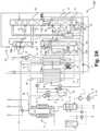
- FIGS 1A and 2A embodiments of air separation plants 100 and 200 are illustrated in the mixed production mode explained several times above, in which nitrogen and oxygen products are produced in parallel, whereas the Figures 1B and 2B show the corresponding plants 100 and 200 in the nitrogen production mode, in which essentially nitrogen is provided as an air product.
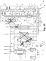
- the Figures 1C and 2C illustrate alternatives. The process components that are not in operation are shown crossed out. In the following, Figure 1A explained. The Figures 1B , 1C , 2B and 2C The systems and process modes illustrated are then only described with regard to the Figure 1A different characteristics. The Figure 1A The explanations given continue to apply.
- Feed air A is sucked in from the atmosphere via a filter 2 using a main air compressor 1 and compressed to a suitable pressure level.
- the compressed feed air A is then cooled with water using a direct contact cooler 3 and adsorbed to remove water and carbon dioxide in a prepurification unit 4.
- the appropriately treated feed air, now designated B, is divided into partial streams C, D and E.
- Partial stream C is passed through one or more first compressor stages of a secondary compressor 5 and then divided again into partial streams F and H.
- the partial stream F is further compressed in one or more second compressor stages of the secondary compressor 5, then at least partially liquefied in a main heat exchanger 6, expanded in an expansion turbine (Joule-Thomson turbine) 7 coupled to a generator G, and fed into a pressure column 11 of a rectification column system 10 which, in addition to the pressure column 11, has a low-pressure column 12 and an argon discharge column 13.
- the partial flow H is further compressed in a booster of a booster turbine 8, then partially cooled in the main heat exchanger 6, expanded in an expansion machine of the booster turbine 8 and then also fed into the pressure column 11, together with the partial flow D and the partial flow E, which are cooled to suitable temperatures in the main heat exchanger 6 on the one hand and in a secondary heat exchanger 6a on the other hand.
- the pressure column 11 and the low-pressure column 12 are connected in a heat-exchanging manner via a main condenser 11a, in which the top gas of the pressure column is condensed against the bottom liquid of the low-pressure column 12.
- the corresponding condensate K is returned to the pressure column 11.
- Additional top gas of the pressure column 11 can be heated in the form of a material flow L in the secondary heat exchanger 6a and then fed to a multi-stage compressor arrangement 9 at an intermediate stage or to a separate compressor, where it is combined with nitrogen-rich top gas M of the low-pressure column 12, which was heated in a counter-current subcooler 15 and then in the main heat exchanger 6 and then fed to the compressor arrangement 9 on the suction side. In this way, a nitrogen product N can be provided.
- the low-pressure column 12 is fed using liquids that are taken from the pressure column 11. This is initially bottom liquid O, which is led through the subcooling countercurrent 15 and then fed into a middle region of the low-pressure column 12 on the one hand and into an evaporation chamber of a top condenser 13a of the argon discharge column 13 on the other. Here, evaporated and unevaporated portions are fed into the low-pressure column 12 in the form of material flows P. There is also liquid Q, which is taken from the pressure column 11 at the feed point of the partial flow F into the pressure column 11, led through the subcooling countercurrent 15 and fed into the low-pressure column 12 at the designated point. Other liquids are a liquid R taken via an intermediate extraction point and overhead gas condensate S. These are also passed through the subcooling countercurrent 15 and fed into the low-pressure column 12 at the designated points. The liquid R is the "impure" liquid nitrogen return discussed above.
- the argon discharge column 13 is connected in a manner known per se to the low-pressure column 12 at the argon maximum or another location via material flows T.
- top gas condensate U from the argon discharge column 13 which is heated in the secondary heat exchanger 6a, an appropriately designated argon product is provided.
- Bottom liquid V from the low-pressure column 12 is pressurized in a pump 16, heated and evaporated in the main heat exchanger 6 and in this way as appropriate
- a purge removal W is provided in the Figure 1A
- the mixed production mode shown is not carried out because this function is fulfilled by the internal compaction product V.
- Residual gas X is discharged from the low pressure column 12 and in the Figure 1A shown mixed production mode from the air separation plant 100 is carried out without expanding a partial flow Y in a generator turbine 17.
- heating can take place in the main and secondary heat exchangers 6, 6a and then use in the warm part of the plant 100, as is generally known from the field of air separation.
- Annex 100 is in accordance with Figure 1A in the nitrogen production mode, in which the secondary compressor 5, the main air compressor 6, the generator turbine 7, the booster turbine 8 and the argon discharge column 13 are not in operation.
- the low-pressure column 12 is only fed with the bottom liquid of the pressure column 11, which is only fed into an area below the lowest separation section of the low-pressure column 12, as illustrated with a material flow Z.
- a partial flow Y of the residual gas X is taken from the secondary heat exchanger 6a at an intermediate temperature level, expanded in the generator turbine 17 and then heated again in the secondary heat exchanger 6a. In this way, "cold" can be generated.
- a purge removal is carried out, as illustrated with W.
- the nitrogen-rich top gas M of the low-pressure column 12 is only formed in the mixed production mode and is available in the Figure 1B
- the nitrogen product formed here exclusively, ie the nitrogen stream L, is in particular exclusively produced using a second product compressor, ie the one in Figure 1B downstream illustrated stage(s) of the compressor arrangement 9.
- FIG 1C an air separation plant 100 is illustrated in which, as an alternative to the residual gas turbine 17, a generator turbine 17a is used in which feed air is expanded into the pressure column 11. It is a nitrogen production mode The generator turbine 17a is not in use in the mixed production mode.
- the plant 200 illustrated in the mixed production mode has an additional column 14.
- the feed air A is compressed by means of the main air compressor 1 to a pressure level of, for example, approx. 9 to 10 bar.
- the additional column 14 is fed with the partial flows D and E of the feed air. It has a top condenser 14a, the evaporation space of which is fed with feed air of the partial flow F, a partial flow of which is expanded by means of a generator turbine 18.
- Bottom liquid O1 of the additional column 14 is also fed into the top condenser 14a. Further feed air of the partial flow F is fed into the pressure column 11, as designated by F1.
- An additional return to the additional column 14 is provided in the form of the material flow S.
- the top condenser 14a is also used to condense top gas from the additional column 14. Uncondensed top gas can be provided in the form of the nitrogen product N. A purge stream or excess liquid can be withdrawn from the top condenser 14a as a material stream F2 and fed into the pressure column 11. Alternatively, the material stream F2 can be fed into the low-pressure column 12.
- the material stream S is fed into the additional column 14 using a pump not specifically designated, which is also referred to as a return pump.
- This pump is used in particular in the nitrogen production mode, but can also be used in the mixed production mode.
- the mixed production mode of the plant 200 differs from the nitrogen production mode of the plant 200 as previously described with respect to Figures 1A and 1B to Annex 100.
- the above explanations and the corresponding differences in the Figures 2A and 2B can therefore be referred to.
- FIG 2C an air separation plant 200 is illustrated in which, as an alternative to the residual gas turbine 17, a generator turbine 17a is used in which feed air is expanded into the additional column 14. A nitrogen production mode is illustrated. The generator turbine 17a is not used in the mixed production mode.
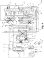
- FIG 3 an air separation plant 300 is illustrated and shown in a nitrogen production mode.
- bottom liquid O of the pressure column 11 is fed into a condensation chamber of the top condenser 14a of the additional column 14 using a pump 301.
- Liquid indicated here as F3 is withdrawn from the condensation chamber of the top condenser 14a of the additional column 14 and fed into the low-pressure column.
- the other operating modes of the air separation plant 300 are shown in conjunction with the Figures 2A or 2B.
- the portion F1 of the feed air is fed into the low-pressure column 12 in the mixed production mode, as is a partial stream of the liquid F3.
Landscapes
- Engineering & Computer Science (AREA)
- Physics & Mathematics (AREA)
- Mechanical Engineering (AREA)
- Thermal Sciences (AREA)
- General Engineering & Computer Science (AREA)
- Power Engineering (AREA)
- Health & Medical Sciences (AREA)
- Emergency Medicine (AREA)
- Separation By Low-Temperature Treatments (AREA)
Abstract
Es wird ein Verfahren zur Tieftemperaturzerlegung von Luft unter Verwendung einer Luftzerlegungsanlage (100-300) vorgeschlagen, wobei die Luftzerlegungsanlage (100-300) ein Rektifikationskolonnensystem (10) mit einer Druckkolonne (11) und einer Niederdruckkolonne (12) aufweist, unter Verwendung von in dem Rektifikationskolonnensystem (10) gebildetem Kopfgas ein oder mehrere Stickstoffprodukte und von Sumpfflüssigkeit der Niederdruckkolonne (12) ein oder mehrere Sauerstoffprodukte gebildet werden, und die Niederdruckkolonne (12) unter Verwendung von Sumpfflüssigkeit aus der Druckkolonne (11) gespeist wird. Hierbei ist ein Mischproduktionsmodus und ein Stickstoffproduktionsmodus umfasst, wobei in dem Mischproduktionsmodus das oder die Sauerstoffprodukte in einer Sauerstoffproduktgesamtmenge und das oder die Stickstoffprodukte in einer ersten Stickstoffproduktgesamtmenge bereitgestellt werden, in dem Stickstoffproduktionsmodus das oder die Sauerstoffprodukte nicht, und das oder die Stickstoffprodukte in einer zweiten Stickstoffproduktgesamtmenge, die gleich oder unterschiedlich zu der ersten Stickstoffproduktgesamtmenge ist, bereitgestellt werden, die erste Stickstoffproduktgesamtmenge 50% bis 150% der Sauerstoffproduktgesamtmenge beträgt, die zur Speisung der Niederdruckkolonne (12) verwendete Sumpfflüssigkeit der Druckkolonne (11) in dem Mischproduktionsmodus ausschließlich oberhalb eines untersten Trennabschnitts der Niederdruckkolonne (12) in die Niederdruckkolonne (12) eingespeist wird, und die zur Speisung der Niederdruckkolonne (12) verwendete Sumpfflüssigkeit der Druckkolonne (11) in dem Stickstoffproduktionsmodus zumindest zu einem Teil unterhalb eines untersten Trennabschnitts der Niederdruckkolonne (12) in die Niederdruckkolonne (12) eingespeist wird. Ein Verfahren zur Herstellung von Ammoniak und entsprechende Anlagen (100-300) sind ebenfalls Gegenstand der Erfindung.
Description
- Die Erfindung betrifft ein Verfahren zur Tieftemperaturzerlegung von Luft, ein Verfahren zur Herstellung von Ammoniak und entsprechende Anlagen mit den jeweiligen Merkmalen der unabhängigen Patentansprüche.
- Ammoniak kann als Speicher- und Transportform für Wasserstoff verwendet werden. Ammoniak ist typischerweise einfacher zu handhaben als komprimiertes oder verflüssigtes Wasserstoffgas. Die Synthese von Ammoniak aus Wasserstoff und Stickstoff ist ein bewährtes Verfahren der chemischen Industrie und beispielsweise im Artikel "Ammonia, 2. Production Processes" in Ullmann's Encyclopedia of Industrial Chemistry vom 15. Oktober 2011, DOI: 10.1002/14356007.o02_o11, beschrieben.
- Wie in einem Artikel von Alexander H. Tullo, "Is ammonia the fuel of the future?", Chemical and Engineering News 2021, Band 99, Ausgabe 8, zusammengefasst, weist Ammoniak mit 12,7 MJ/L eine höhere Energiedichte als sogar flüssiger Wasserstoff mit 8,5 MJ/L auf. Flüssiger Wasserstoff muss bei kryogenen Bedingungen von -253 °C gelagert werden, während Ammoniak bei nur -33 °C gelagert werden kann. Zudem weist Ammoniak zwar gewisse Risiken in der Handhabung auf, ist aber beispielsweise deutlich schwerer entzündlich als Wasserstoff. Da Ammoniak als Ausgangsstoff für Düngemittel in der Landwirtschaft und als chemischer Rohstoff weit verbreitet ist, existiert eine weltweit ausgebaute Ammoniak-Infrastruktur. Derzeit werden jährlich etwa 180 Millionen Tonnen Ammoniak produziert und 20 Millionen Tonnen gehandelt. 120 Häfen weltweit sind bereits mit Ammoniak-Terminals ausgestattet.
- Um regenerativ erzeugten elektrischen Strom zu nutzen und Kohlendioxidemissionen bei der Herstellung von Wasserstoff als Ausgangsstoff für die Ammoniaksynthese weitgehend zu reduzieren, kann die Wasserelektrolyse eingesetzt werden. Entsprechende Verfahren können in unterschiedlichen Ausgestaltungen durchgeführt werden. Der elektrolytisch und unter Einsatz regenerativ erzeugten elektrischen Stroms hergestellte Wasserstoff wird auch als "grüner" Wasserstoff bezeichnet.
- Die Erzeugung von Wasserstoff als Ausgangsstoff für die Ammoniaksynthese im großtechnischen Maßstab erfolgt derzeit jedoch noch überwiegend auf Basis von Kohlenwasserstoffen. Entsprechende Verfahren sind in gängigen Nachschlagewerken, beispielsweise im Artikel "Hydrogen" in Ullmann's Encyclopedia of Industrial Chemistry vom 15. Juni 2000, DOI: 10.1002/14356007.a13_297, beschrieben. Entsprechend hergestellter Wasserstoff wird auch als "grauer" Wasserstoff bezeichnet.
- Zumindest bis zur wirtschaftlich erfolgreichen Realisierung von Verfahren zur Herstellung von grünem Wasserstoff können Brückentechnologien eingesetzt werden. Diese umfassen insbesondere die Rückgewinnung und anschließende Lagerung oder Verwendung von Kohlendioxid (engl. Carbon (Dioxide) Capture and Storage, CCS bzw. Carbon (Dioxide) Capture and Utilization, CCU). Entsprechend hergestellter Wasserstoff wird auch als "blauer" Wasserstoff bezeichnet.
- Zur Herstellung von Wasserstoff aus Kohlenwasserstoffen können katalytische Reformierungsverfahren wie Dampfreformierung (engl. Steam Methane Reforming, SMR) oder autotherme Reformierung (engl. Autothermal Reforming, ATR) zum Einsatz kommen. Ein weiterer Weg zur Herstellung von Wasserstoff aus entsprechenden Kohlenstoffquellen umfasst die katalytische partielle Oxidation (POX, Partial Oxidation). Auch Kombinationen entsprechender Verfahren können eingesetzt werden.
- Kombinierte Verfahren, die die Herstellung von Ammoniak aus blauem oder grauem Wasserstoff und die Herstellung des Wasserstoffs selbst, insbesondere mittels autothermer Reformierung, umfassen, benötigen zunächst Sauerstoff für die Wasserstoffherstellung und anschließend Stickstoff für die Ammoniaksynthese. Beide Gase lassen sich mittels Tieftemperaturzerlegung von Luft bereitstellen.
- Auch zur Tieftemperaturzerlegung von Luft sei auf einschlägige Fachliteratur, beispielsweise H.-W. Häring (Hrsg.), Industrial Gases Processing, Wiley-VCH 2006, insbesondere Abschnitt 2.2.5, "Cryogenic Rectification", verwiesen. Luftzerlegungsanlagen weisen Rektifikationskolonnensysteme auf, die beispielsweise als Zweikolonnensysteme, insbesondere als klassische Linde-Doppelkolonnensysteme, aber auch als Drei- oder Mehrkolonnensysteme ausgebildet sein können. Neben den Rektifikationskolonnen zur Gewinnung von Stickstoff und/oder Sauerstoff in flüssigem und/oder gasförmigem Zustand (beispielsweise flüssigem Sauerstoff, LOX, gasförmigem Sauerstoff, GOX, flüssigem Stickstoff, LIN und/oder gasförmigem Stickstoff, GAN), also Rektifikationskolonnen zur Stickstoff-Sauerstoff-Trennung, können Rektifikationskolonnen zur Gewinnung weiterer Luftkomponenten, insbesondere der Edelgase Krypton, Xenon und/oder Argon, vorgesehen sein.
- Es besteht der Bedarf nach Verfahren und Anlagen, die insbesondere den Bedarf an den unterschiedlichen Luftprodukten Sauerstoff und Stickstoff im Zuge der Wasserstoff- und nachfolgenden Ammoniaksynthese decken können.
- Vor diesem Hintergrund werden ein Verfahren zur Tieftemperaturzerlegung von Luft und ein Verfahren zur Herstellung von Ammoniak sowie entsprechende Anlagen mit den jeweiligen Merkmalen der unabhängigen Patentansprüche vorgeschlagen. Ausgestaltungen sind jeweils Gegenstand der abhängigen Patentansprüche sowie der nachfolgenden Beschreibung.
- Die hier vorgeschlagenen Maßnahmen ermöglichen insbesondere einen Betrieb einer zur Bereitstellung von Stickstoff und Sauerstoff eingerichteten Luftzerlegungsanlage als reine oder im Wesentlichen reine Stickstoffanlage, wenn Sauerstoff nicht benötigt wird. Dies gilt beispielsweise für die Ammoniaksynthese, in der im Gegensatz zur Herstellung von Wasserstoff, beispielsweise mittels autothermer Reformierung, kein Sauerstoff benötigt wird. Die vorliegende Erfindung eignet sich insbesondere auch dann für die Versorgung einer Ammoniaksynthese, wenn die Wasserstoffherstellung dauerhaft oder zeitweise zur Bereitstellung von grünem Wasserstoff umgerüstet wird. Eine hier vorgeschlagene Luftzerlegungsanlage kann also zunächst zur Versorgung einer grauen oder blauen Wasserstoffsynthese in Verbindung mit einer Ammoniaksynthese genutzt werden und anschließend an eine entsprechende Umrüstung energieeffizient weiter betrieben werden. Dies gilt auch beispielsweise dann, wenn eine zeitweise grüne Wasserstoffherstellung, beispielsweise bei Verwendung in fluktuierenden Mengen bereitgestelltem regenerativ erzeugtem elektrischem Strom, erfolgt. Mit anderen Worten ermöglichen es die hier vorgeschlagenen Maßnahmen, eine Luftzerlegungsanlage dauerhaft oder zeitweise in einem Stickstoffproduktionsbetrieb zu betreiben und in diesem Zusammenhang auf die Produktion nicht mehr benötigten Sauerstoffs zu verzichten.
- Das vorgeschlagene Verfahren dient zur Tieftemperaturzerlegung von Luft und wird unter Verwendung einer Luftzerlegungsanlage durchgeführt, die ein Rektifikationskolonnensystem mit einer Druckkolonne und einer Niederdruckkolonne aufweist. Unter Verwendung von in dem Rektifikationskolonnensystem gebildetem Kopfgas einer oder mehrerer Rektifikationskolonnen, insbesondere von Kopfgas der Druckkolonne, aber auch zusätzlich oder alternativ von Kopfgas einer weiteren Rektifikationskolonne, wie beispielsweise in
Figur 2 veranschaulicht, werden ein oder mehrere Stickstoffprodukte und von Sumpfflüssigkeit der Niederdruckkolonne ein oder mehrere Sauerstoffprodukte gebildet. Die Niederdruckkolonne wird unter Verwendung von Sumpfflüssigkeit der Druckkolonne gespeist. - Ein "Kopfgas" ist dabei ein in einem oberen Teil, insbesondere oberhalb des obersten Trennabschnitts, einer Rektifikationskolonne erhaltenes Gas. Eine "Sumpfflüssigkeit" ist eine in einem unteren Teil, insbesondere unterhalb des untersten Trennabschnitts, einer Rektifikationskolonne erhaltene Flüssigkeit. Mit der Angabe "unter Verwendung von Sumpfflüssigkeit der Druckkolonne" soll dabei eine direkte Einspeisung der Sumpfflüssigkeit der Druckkolonne in die Niederdruckkolonne verstanden werden, aber auch eine Zwischenverwendung solcher Sumpfflüssigkeit umfasst sein. Auch eine Einspeisung in einen Kopfkondensator einer weiteren Rektifikationskolonne, wie beispielsweise in
Figur 3 veranschaulicht, kann hiervon umfasst sein. In einem solchen Fall wird dem Kopfkondensator der weiteren Rektifikationskolonne Flüssigkeit entnommen und diese wird in die Niederdruckkolonne eingespeist. Auch diese Flüssigkeit ist aufgrund der Einspeisung der Sumpfflüssigkeit der Druckkolonne in den Kopfkondensator "unter Verwendung von Sumpfflüssigkeit der Druckkolonne" gebildet, selbst wenn in den Kopfkondensator weitere Fluide eingespeist werden sollten bzw. die Flüssigkeit eine zusammensetzungsmäßige Veränderung erfährt. - In dem vorgeschlagenen Verfahren sind ein Mischproduktionsmodus und ein Stickstoffproduktionsmodus vorgesehen, wobei in dem Mischproduktionsmodus das oder die Sauerstoffprodukte in einer Sauerstoffproduktgesamtmenge und das oder die Stickstoffprodukte in einer ersten Stickstoffproduktgesamtmenge bereitgestellt und aus der Luftzerlegungsanlage ausgeführt werden, und in dem Stickstoffproduktionsmodus das oder die Sauerstoffprodukte nicht, und das oder die Stickstoffprodukte in einer zweiten Stickstoffproduktgesamtmenge, die gleich oder unterschiedlich zu der ersten Stickstoffproduktgesamtmenge ist, bereitgestellt und aus der Luftzerlegungsanlage ausgeführt werden. Die erste Stickstoffproduktgesamtmenge kann insbesondere 50% bis 150% der Sauerstoffproduktgesamtmenge betragen.
- Die zur Speisung der Niederdruckkolonne verwendete Sumpfflüssigkeit der Druckkolonne, oder eine unter Verwendung hiervon gebildete Flüssigkeit (wie insbesondere in dem erläuterten Fall einer weiteren Rektifikationskolonne in Form einer Flüssigkeit aus deren Kopfkondensator der Fall) wird in dem Mischproduktionsmodus ausschließlich oberhalb eines untersten Trennabschnitts, d.h. oberhalb des untersten Siebbodens, der untersten Packung und dergleichen, der Niederdruckkolonne in die Niederdruckkolonne eingespeist. Die Einspeisung kann aber auch an unterschiedlichen Einspeisestellen erfolgen, wie typischerweise in Verfahren mit Argongewinnung der Fall. Eine Einspeisung direkt in den Sumpf erfolgt dagegen in dem Mischproduktionsmodus nicht, um das gebildete Sauerstoffprodukt nicht mit Stickstoff zu verunreinigen.
- Die zur Speisung der Niederdruckkolonne verwendete Sumpfflüssigkeit der Druckkolonne, oder eine unter Verwendung hiervon gebildete Flüssigkeit (wie insbesondere in dem erläuterten Fall einer weiteren Rektifikationskolonne in Form einer Flüssigkeit aus deren Kopfkondensator der Fall) wird in dem Stickstoffproduktionsmodus dagegen zumindest zum Teil unterhalb eines untersten Trennabschnitts der Niederdruckkolonne in die Niederdruckkolonne eingespeist. In dem Stickstoffproduktionsmodus wird kein Sauerstoffprodukt gewonnen und durch eine entsprechende Einspeisung wird im Wesentlichen eine Bereitstellung von Flüssigkeit zur Kühlung des Hauptkondensators erzielt.
- In beiden Fällen soll ein "Trennabschnitt" insbesondere eine Anordnung aus einer oder mehreren Trennstrukturen, d.h. geordneten oder ungeordneten Packungen und/oder Siebböden, bezeichnen, wobei ein Trennabschnitt auch mehrere sogenannte Sektionen oder Unterabschnitte aufweisen kann, zwischen denen aber insbesondere keine wesentliche Ein- und Ausspeisung von Flüssigkeit erfolgt.
- Durch die vorgeschlagenen Maßnahmen kann die Niederdruckkolonne in dem Stickstoffproduktionsmodus gewissermaßen außer Betrieb gesetzt werden. Die Niederdruckkolonne kann durch den Einsatz der vorliegenden Erfindung im Wesentlichen zur Bereitstellung eines Kühlfluids im Sumpf verwendet werden, gegen das Kopfgas der Druckkolonne kondensiert wird. Aus dem Sumpf der Niederdruckkolonne kann in dem Stickstoffproduktionsmodus im Wesentlichen nur eine sogenannte Purgeentnahme vorgenommen werden, um auf diese Weise die Anreicherung von unerwünschten Komponenten wie Kohlenwasserstoffen im Sumpf der Niederdruckkolonne zu verhindern.
- In bestimmten Ausgestaltungen kann die vorgeschlagene Luftzerlegungsanlage eine Argonkolonne im unten erläuterten Sinn aufweisen, wobei die Argonkolonne in dem Stickstoffproduktionsmodus nicht betrieben wird. Dies geht mit der hier vorgeschlagenen Deaktivierung der Sauerstoffproduktion einher. Die Argonkolonne kann insbesondere als Argongewinnungskolonne oder Argonausschleuskolonne betrieben werden. Auf die Definitionen unten wird verwiesen.
- In Ausgestaltungen der Erfindung kann der Niederdruckkolonne Restgas entnommen werden, wobei das Restgas nur in dem Stickstoffproduktionsmodus unter Verwendung einer Restgasturbine entspannt und aus der Luftzerlegungsanlage ausgeschleust wird. Auf diese Weise kann insbesondere eine Anpassung an den Kältebedarf vorgenommen werden. Wie erwähnt, erfolgt in dem Mischproduktionsmodus insbesondere eine Entspannung von Einsatzluft, die in Ausgestaltungen der Erfindung in dem Stickstoffproduktionsmodus nicht vorgenommen wird.
- Das Rektifikationskolonnensystem kann dabei mit in einer
Hauptluftverdichteranordnung verdichteter Luft gespeist werden, wobei die in der Hauptluftverdichteranordnung verdichtete Luft, oder ein Teil hiervon, nur in dem Mischproduktionsmodus unter Verwendung eines Nachverdichters und/oder eines oder mehrerer Booster verdichtet und/oder unter Verwendung einer oder mehrerer Entspannungsturbinen entspannt wird. Der Betrieb entsprechender drehender Maschinen kann also im Wesentlichen wegfallen, wenn Sauerstoff nicht benötigt wird. Auf diese Weise ergeben sich auch Energieeinsparungen. - Der Begriff "Hauptluftverdichteranordnung" soll hier eine Anordnung aus einem oder mehreren, insbesondere parallel angeordneten, Hauptluftverdichtern bezeichnen. In einer Ausgestaltung der Erfindung umfasst die Hauptluftverdichteranordnung dabei zwei Hauptluftverdichter, von denen in dem Mischproduktionsmodus beide, insbesondere jeweils in Volllast betrieben werden, und von denen in dem Stickstoffproduktionsmodus nur einer, insbesondere in Vollast, betrieben wird.
- In Ausgestaltungen eines entsprechenden Verfahrens wird weiteres Kopfgas der Druckkolonne oder ein anderes stickstoffhaltiges Fluid aus der Druckkolonne nur in dem Mischproduktionsmodus in verflüssigtem Zustand oberhalb eines obersten Trennabschnitts der Niederdruckkolonne in die Niederdruckkolonne eingespeist. Dies gilt auch für andere Fluide und ihre Einspeisung in die Niederdruckkolonne. Ein anderes stickstoffhaltiges Fluid aus der Druckkolonne, das entsprechend verwendet wird, kann insbesondere eine Rücklaufflüssigkeit sein, die der Druckkolonne nicht direkt am Kopf, sondern einige (z.B. 5 bis 15) Trennstufen unterhalb des Kopfs entnommen wird. In diesem Fall wird auch von einem "unreinen" Flüssigstickstoffrücklauf gesprochen. Dies kann insbesondere dann der Fall bzw. vorteilhaft sein, wenn in dem Mischproduktionsmodus das gesamte Stickstoffprodukt aus der Druckkolonne entnommen wird (und keine Entnahme von Niederdruckstickstoff aus der Niederdruckkolonne erfolgt), sowie eine entsprechende Anlage beispielsweise nur eine Argon-Ausschleuskolonne aufweist. Dies kann beispielsweise bei einem Dreikolonnenverfahren der Fall sein, wie es in
Figur 2 gezeigt ist. - Eine entsprechende Luftzerlegungsanlage kann eine Zusatzkolonne zur Stickstoffgewinnung im unten erläuterten Sinn aufweisen, auf die auch zuvor bereits Bezug genommen wurde. Bei einem höheren Betriebsdruck dieser Zusatzkolonne kann die weitere Verdichtung bzw. die Vor-Verdichtung von Stickstoff aus dieser Zusatzkolonne entfallen. Das Verfahren eignet sich also auch für entsprechende Dreikolonnenverfahren. Die Zusatzkolonne weist in diesem Fall einen Kopfkondensator auf, der einen Verdampfungsraum umfasst, in den abgekühlte und verflüssigte oder pseudo-verflüssigte Druckluft und/oder Sumpfflüssigkeit der Zusatzkolonne eingespeist werden, und aus dem Fluidströme entnommen werden, die in die erste Druckkolonne eingespeist werden. Der Begriff "Pseudo-Verflüssigung" soll dabei eine Überführung aus dem überkritischen in den flüssigen Zustand durch Wärmeabfuhr bezeichnen. Wie erwähnt, kann auch Flüssigkeit aus einem entsprechenden Kopfkondensator in die Niederdruckkolonne eingespeist werden, so dass auch in diesem Fall die Niederdruckkolonne "unter Verwendung von Sumpfflüssigkeit der Druckkolonne" gespeist wird, bzw. mit einer unter Verwendung hiervon gebildeten Flüssigkeit.
- Die in den Verdampfungsraum des Kopfkondensators der Zusatzkolonne eingespeiste abgekühlte und verflüssigte bzw. pseudo-verflüssigte Druckluft wird insbesondere nur in dem Mischproduktionsmodus in den Verdampfungsraum des Kopfkondensators der Zusatzkolonne eingespeist und dabei zuvor turbinenentspannt. Das Kopfgas der Zusatzkolonne kann das Kopfgas sein, das in dem vorgeschlagenen Verfahren als Stickstoffprodukt bereitgestellt wird. Es kann aber auch zur Bereitstellung eines zusätzlichen Stickstoffprodukts verwendet werden.
- Die Luftzerlegungsanlage kann in Ausgestaltungen einen Hauptwärmetauscher und einen Nebenwärmetauscher umfassen und zumindest ein Teil von Einsatzluft, die in das Rektifikationskolonnensystem eingespeist wird, kann parallel in dem Hauptwärmetauscher und dem Nebenwärmetauscher abgekühlt werden. Auf diese Weise kann die Wärmeaustauschfläche selektiv an die Betriebsweise angepasst werden, insbesondere indem der Hauptwärmetauscher in dem Stickstoffproduktionsmodus nicht betrieben wird. Zusätzlich kann in dem Nebenwärmetauscher zumindest ein Teil des in dem Rektifikationskolonnensystem gebildeten und zur Bereitstellung des einen oder der mehreren Stickstoffprodukten verwendeten Kopfgases erwärmt werden. Dieser Nebenwärmetauscher kann daher in entsprechenden Ausgestaltungen durchgängig in Betrieb sein.
- In Ausgestaltungen der Erfindung kann in das Rektifikationskolonnensystem eingespeiste Luft in dem Mischproduktionsmodus nicht oder in einer geringeren Menge als in dem Stickstoffproduktionsmodus unter Verwendung einer Entspannungsturbine entspannt und aus der Luftzerlegungsanlage ausgeschleust wird. Auf diese Weise kann ebenfalls eine Anpassung an den Kältebedarf vorgenommen werden, und zwar insbesondere als Alternative zur Entspannung von Restgas.
- In dem vorgeschlagenen Verfahren kann das Rektifikationskolonnensystem insbesondere unter Verwendung von Druckluft gespeist werden, die nur in dem Stickstoffproduktionsmodus unter Verwendung einer Entspannungsturbine, insbesondere einer Generatorturbine, in eine oder mehrere Rektifikationskolonnen des Rektifikationskolonnensystems, insbesondere die Druckkolonne und/oder, bei einem Dreikolonnenverfahren, eine Zusatzkolonne, eingespeist wird.
- Das vorgeschlagene Verfahren zur Herstellung von Ammoniak umfasst eine Wasserstoffproduktion und eine Ammoniaksynthese, wobei in der Wasserstoffproduktion gebildeter Wasserstoff in der Ammoniaksynthese mit Stickstoff zu Ammoniak umgesetzt wird, und wobei die Wasserstoffproduktion die Verwendung von Sauerstoff umfasst. Der Sauerstoff und der Stickstoff können jeweils zumindest zu einem Teil unter Verwendung eines Verfahrens nach einem der vorstehenden Ansprüche bereitgestellt werden.
- Insbesondere kann die Wasserstoffproduktion in einem ersten Zeitraum unter Verwendung eines sauerstoffverbrauchenden Verfahrens und in einem zweiten Zeitraum elektrolytisch erfolgen, wobei der Mischproduktionsmodus der Luftzerlegungsanlage in dem ersten und der Stickstoffproduktionsmodus in dem zweiten Zeitraum erfolgen kann. Die Wasserstoffproduktion kann insbesondere eine autotherme Reformierung eines kohlenwasserstoffhaltigen Einsatzes umfassen, für die der Sauerstoff benötigt wird.
- Die vorliegende Erfindung kann insbesondere im Zusammenhang mit der Herstellung von blauem Wasserstoff erfolgen, d.h. das Verfahren kann die Abscheidung und Verwendung und/oder Speicherung von Kohlendioxid umfassen.
- Die vorgeschlagene Luftzerlegungsanlage umfasst ein Rektifikationskolonnensystem mit einer Druckkolonne und einer Niederdruckkolonne. Sie ist eingerichtet, unter Verwendung von Kopfgas der Druckkolonne ein oder mehrere Stickstoffprodukte und von Sumpfflüssigkeit der Niederdruckkolonne ein oder mehrere Sauerstoffprodukte zu bilden, und die Niederdruckkolonne unter Verwendung von Sumpfflüssigkeit der Druckkolonne zu speisen. Zu weiteren Merkmalen einer solchen Luftzerlegungsanlage sei auf den entsprechenden unabhängigen Patentanspruch verwiesen.
- Die vorgeschlagene Anlage zur Herstellung von Ammoniak weist eine Wasserstoffproduktionseinheit und eine Ammoniaksyntheseeinheit sowie eine Luftzerlegungsanlage auf, wie sie soeben erläutert wurde.
- Zu weiteren Merkmalen und Vorteilen der vorgeschlagenen Anlagen und Ausgestaltungen hiervon sei auf die obigen Erläuterungen betreffend der erfindungsgemäß vorgeschlagenen Verfahren und ihrer Ausgestaltungen ausdrücklich verwiesen, da diese hierfür in gleicher Weise gelten.
- Entsprechendes gilt auch für entsprechende Anlagen, die gemäß Ausgestaltungen der Erfindung dazu eingerichtet sind, Verfahren gemäß beliebiger Ausgestaltungen der vorliegenden Erfindung durchzuführen.
-
-
Figuren 1A-1C veranschaulichen Luftzerlegungsanlagen gemäß Ausgestaltungen der Erfindung in unterschiedlichen Betriebsmodi. -
Figuren 2A-2C veranschaulichen Luftzerlegungsanlagen gemäß Ausgestaltungen der Erfindung in unterschiedlichen Betriebsmodi. -
Figur 3 veranschaulicht eine Luftzerlegungsanlage gemäß einer Ausgestaltung der Erfindung in einem Betriebsmodus. - Die nachfolgend beschriebenen Ausführungsformen werden lediglich zu dem Zweck beschrieben, den Leser beim Verständnis der beanspruchten und zuvor erläuterten Merkmale zu unterstützen. Sie stellen lediglich repräsentative Beispiele dar und sollen hinsichtlich der Merkmale der Erfindung nicht abschließend und/oder beschränkend betrachtet werden. Es versteht sich, dass die zuvor und nachfolgend beschriebenen Vorteile, Ausführungsformen, Beispiele, Funktionen, Merkmale, Strukturen und/oder anderen Aspekte nicht als Beschränkungen des Umfangs der Erfindung, wie er in den Ansprüchen definiert ist, oder als Beschränkungen von Äquivalenten zu den Ansprüchen zu betrachten sind, und dass andere Ausführungsformen verwendet und Änderungen vorgenommen werden können, ohne vom Umfang der beanspruchten Erfindung abzuweichen.
- Unterschiedliche Ausführungsformen der Erfindung können weitere zweckmäßige Kombinationen der beschriebenen Elemente, Komponenten, Merkmale, Teile, Schritte, Mittel usw. umfassen, aufweisen, aus ihnen bestehen oder im Wesentlichen aus ihnen bestehen, auch wenn solche Kombinationen hier nicht spezifisch beschrieben sind. Darüber hinaus kann die Offenbarung andere Erfindungen umfassen, die gegenwärtig nicht beansprucht sind, die aber in Zukunft beansprucht werden können, insbesondere wenn sie vom Umfang der unabhängigen Ansprüche umfasst sind.
- Erläuterungen, die sich auf Vorrichtungen, Apparate, Anordnungen, Systeme usw. gemäß Ausführungsformen der vorliegenden Erfindung beziehen, können auch für Verfahren, Prozesse, Methoden usw. gemäß den Ausführungsformen der vorliegenden Erfindung gelten und umgekehrt. Gleiche, gleich wirkende, in ihrer Funktion einander entsprechende, baulich identisch oder vergleichbar aufgebaute Elemente, Verfahrensschritte usw. können mit identischen Bezugszeichen angegeben sein.
- Nachfolgend werden vor der Bezugnahme auf die beigefügten Zeichnungen nochmals Begriffe erläutert und definiert, die für sämtliche Ausgestaltungen der vorliegenden Erfindung in derselben Weise gelten können.
- Luftzerlegungsanlagen mit Zusatzkolonnen zur Stickstoffgewinnung sind bekannt. Es kann beispielsweise auf die
EP 3 771 873 A1 verwiesen werden, wo eine derartige Zusatzkolonne als "erste Kolonne" bezeichnet wird. Sämtliche Rektifikationskolonnen können dabei auf unterschiedlichen Druckniveaus betrieben werden. Der Betriebsdruck der Druckkolonne kann beispielsweise auf einem Druckniveau von 4 bis 7 bar, insbesondere ca. 5,3 bar, liegen. Die Niederdruckkolonne kann auf einem Druckniveau von typischerweise 1 bis 2 bar, insbesondere ca. 1,4 bar, betrieben werden. In bestimmten Fällen können in beiden Kolonnen auch höhere Druckniveaus eingesetzt werden. Bei den hier und nachfolgend angegebenen Drücken handelt es sich um Absolutdrücke am Kopf der jeweils angegebenen Kolonnen. Insbesondere zur Bereitstellung von gasförmigem Stickstoff auf einem deutlich überatmosphärischen Druckniveau bei gleichzeitig großen Produktionsmengen können angepasste Luftzerlegungsanlagen verwendet werden, die neben den zwei erläuterten Kolonnen eine die erwähnte Zusatzkolonne zur Stickstoffgewinnung aufweisen, welche bei nochmals höherem Druck, beispielsweise bei 7 bis 11 bar, betrieben wird. Gasförmiger Stickstoff kann als Kopfprodukt aus dieser Zusatzkolonne entnommen werden und muss, falls er bei einem entsprechenden Druckniveau benötigt wird, nicht mehr verdichtet werden, so dass kein entsprechender Verdichter zur Verdichtung von gasförmigem Stickstoff vorhanden ist. Die Zusatzkolonne wird mit einem Kondensatorverdampfer betrieben, der Kopfgas der zusätzlichen Kolonne kondensiert, so dass ein Rücklauf auf die Zusatzkolonne bereitgestellt werden kann. - Bei der Luftzerlegung können sogenannte High-Air-Pressure-Verfahren (HAP-Verfahren) eingesetzt werden. Bei einem HAP-Verfahren wird die gesamte, der Luftzerlegungsanlage zugeführte bzw. die in einem entsprechenden Verfahren insgesamt eingesetzte Luft (als Einsatzluft bezeichnet) in einem Hauptluftverdichter auf einen Druck verdichtet, der deutlich über dem höchsten Betriebsdruck des Rektifikationskolonnensystems, typischerweise also deutlich über dem Betriebsdruck der Hochdrucksäule, liegt. Der Druckunterschied beträgt mindestens 2 oder 4 bar und vorzugsweise zwischen 6 und 16 bar. Beispielsweise ist der Druck mindestens doppelt so hoch wie der Betriebsdruck der Hochdrucksäule. HAP-Verfahren sind z.B. aus der
EP 2 466 236 A1 , derEP 2 458 311 A1 und derUS 5 329 776 A bekannt. - Ferner sind Verfahren bekannt, bei denen die Einsatzluft in dem Hauptluftverdichter nur auf den höchsten Betriebsdruck des Rektifikationskolonnensystems, typischerweise also nur den Betriebsdruck der Hochdrucksäule oder geringfügig darüber, verdichtet wird. Ein Teil der Einsatzluft kann daher nach Abkühlung ohne weitere Entspannung in das Rektifikationskolonnensystem eingespeist werden. Nur bestimmte Anteile, die beispielsweise zur zusätzlichen Kälteproduktion oder auch zur Erwärmung flüssiger Ströme benötigt werden, werden in einem oder mehreren Nachverdichtern weiter verdichtet. Derartige Verfahren mit Haupt- und Nachverdichter(n) werden auch als MAC/BAC-Verfahren (engl. Main Air Compressor/Booster Air Compressor) bezeichnet. Solche Verfahren können in hier beschriebenen Ausgestaltungen eingesetzt werden. In einem MAC/BAC-Verfahren wird also nicht die gesamte Einsatzluft, sondern nur ein Teil auf einen Druck deutlich über dem höchsten Betriebsdruck des Rektifikationskolonnensystems verdichtet.
- Bei der Luftzerlegung kann die sogenannte Innenverdichtung zum Einsatz kommen. Bei der Innenverdichtung wird dem Rektifikationskolonnensystem ein flüssiger Strom entnommen und zumindest zum Teil flüssig auf Druck gebracht. Der flüssig auf Druck gebrachte Strom wird in einem Hauptwärmetauscher der Luftzerlegungsanlage gegen einen Wärmeträger erwärmt und verdampft oder, beim Vorliegen entsprechender Drücke, vom flüssigen in den überkritischen Zustand überführt. Bei dem flüssigen Strom kann es sich insbesondere um flüssigen Sauerstoff, jedoch auch um Stickstoff oder Argon handeln. Die Innenverdichtung wird damit zur Gewinnung entsprechender gasförmiger Druckprodukte eingesetzt. Der Vorteil an Innenverdichtungsverfahren ist unter anderem, dass entsprechende Fluide nicht außerhalb der Luftzerlegungsanlage in gasförmigem Zustand verdichtet werden müssen, was sich häufig als sehr aufwendig erweist und/oder beträchtliche Sicherheitsmaßnahmen erfordert. Auch die Innenverdichtung ist in der eingangs zitierten Fachliteratur beschrieben. Sie kann insbesondere zur Bereitstellung des oder der Sauerstoffprodukte zum Einsatz kommen, wie auch unter Bezugnahme auf die Figuren erläutert.
- Eine "Entspannungsturbine" bzw. "Entspannungsmaschine", die über eine gemeinsame Welle mit weiteren Entspannungsturbinen oder Energiewandlern wie Ölbremsen, Generatoren oder Verdichtern gekoppelt sein kann, ist zur Entspannung eines gasförmigen oder zumindest teilweise flüssigen Stroms eingerichtet. Insbesondere können Entspannungsturbinen zum Einsatz in der vorliegenden Erfindung als Turboexpander ausgebildet sein. Wird ein Verdichter mit einer oder mehreren Entspannungsturbinen angetrieben, jedoch ohne extern, beispielsweise mittels eines Elektromotors, zugeführte Energie, wird der Begriff "turbinengetriebener Verdichter" oder alternativ "Turbinenbooster" verwendet.
- Ein "Verdichter" ist eine Vorrichtung, die zum Verdichten wenigstens eines gasförmigen Stroms von wenigstens einem Eingangsdruck, bei dem dieser dem Verdichter zugeführt wird, auf wenigstens einen Enddruck, bei dem dieser dem Verdichter entnommen wird, eingerichtet ist. Ein Verdichter bildet eine bauliche Einheit, die jedoch mehrere "Verdichterstufen" in Form von Kolben-, Schrauben- und/oder Schaufelrad- bzw. Turbinenanordnungen (also Axial- oder Radialverdichterstufen) aufweisen kann. Dies gilt auch insbesondere für den "Haupt(luft)verdichter" einer Luftzerlegungsanlage, der sich dadurch auszeichnet, dass durch diesen die gesamte oder der überwiegende Anteil der in die Luftzerlegungsanlage eingespeisten Luftmenge, also der gesamte Einsatzluftstrom, verdichtet wird. Ein "Nachverdichter", in dem in MAC/BAC-Verfahren ein Teil der im Hauptluftverdichter verdichteten Luftmenge auf einen nochmals höheren Druck gebracht wird, ist häufig ebenfalls mehrstufig ausgebildet. Insbesondere werden entsprechende Verdichterstufen mittels eines gemeinsamen Antriebs, beispielsweise über eine gemeinsame Welle, angetrieben.
- Herkömmlicherweise kommen in MAC/BAC-Verfahren Nachverdichter zum Einsatz, die mittels extern zugeführter Energie angetrieben werden, in HAP-Verfahren finden sich derartige Nachverdichter typischerweise nicht. Turbinenbooster sind jedoch typischerweise in beiden Fällen vorhanden, insbesondere um bei der Entspannung zur Kälteproduktion freiwerdende Wellenleistung sinnvoll nutzen zu können.
- Ein "Wärmetauscher" dient zur indirekten Übertragung von Wärme zwischen zumindest zwei z.B. im Gegenstrom zueinander geführten Strömen, beispielsweise einem warmen Druckluftstrom und einem oder mehreren kalten Strömen oder einem tiefkalten flüssigen Luftprodukt und einem oder mehreren warmen Strömen. Ein Wärmetauscher kann aus einem einzelnen oder mehreren parallel und/oder seriell verbundenen Wärmetauscherabschnitten gebildet sein, z.B. aus einem oder mehreren Plattenwärmetauscherblöcken. Ein Wärmetauscher, beispielsweise auch der in einer Luftzerlegungsanlage eingesetzte "Hauptwärmetauscher", weist "Passagen" auf, die als voneinander getrennte Fluidkanäle mit Wärmeaustauschflächen ausgebildet sind. Der Begriff "Nebenwärmetauscher" bezeichnet hier einen parallel zu dem Hauptwärmetauscher bereitgestellten Wärmetauscher, durch den ein Teil der Einsatzluft parallel zu dem Hauptwärmetauscher geführt wird.
- Die vorliegende Anmeldung verwendet zur Charakterisierung von Drücken und Temperaturen die Begriffe "Druckniveau" und "Temperaturniveau", wodurch zum Ausdruck gebracht werden soll, dass entsprechende Drücke und Temperaturen in einer entsprechenden Anlage nicht in Form exakter Druck- bzw. Temperaturwerte verwendet werden müssen, um das erfinderische Konzept zu verwirklichen. Jedoch bewegen sich derartige Drücke und Temperaturen typischerweise in bestimmten Bereichen, die beispielsweise ± 1%, 5%, 10%, 20% oder sogar 50% um einen Mittelwert liegen. Entsprechende Druckniveaus und Temperaturniveaus können dabei in disjunkten Bereichen liegen oder in Bereichen, die einander überlappen. Insbesondere schließen beispielsweise Druckniveaus unvermeidliche oder zu erwartende Druckverluste, beispielsweise aufgrund von Abkühlungseffekten, ein. Entsprechendes gilt für Temperaturniveaus.
- In den
Figuren 1A und2A sind jeweils Ausgestaltungen von Luftzerlegungsanlagen 100 und 200 in dem zuvor mehrfach erläuterten Mischproduktionsmodus, in dem Stickstoff- und Sauerstoffprodukte parallel hergestellt werden, veranschaulicht, wohingegen dieFiguren 1B und2B die entsprechenden Anlagen 100 und 200 in dem Stickstoffproduktionsmodus zeigen, in dem im Wesentlichen Stickstoff als Luftprodukt bereitgestellt wird. DieFiguren 1C und2C veranschaulichen Alternativen. Die jeweils nicht in Betrieb befindlichen Verfahrenskomponenten sind dabei durchkreuzt veranschaulicht. Nachfolgend wird dabei zunächstFigur 1A erläutert. Die in denFiguren 1B ,1C ,2B und2C veranschaulichten Anlagen und Verfahrensmodi werden anschließend nur hinsichtlich der zuFigur 1A unterschiedlichen Merkmale erläutert. Die zuFigur 1A getroffenen Erläuterungen gelten dabei weiter. - In der Luftzerlegungsanlage 100 gemäß
Figur 1A wird Einsatzluft A mittels eines Hauptluftverdichters 1 aus der Atmosphäre über einen Filter 2 angesaugt und auf ein geeignetes Druckniveau verdichtet. Die verdichtete Einsatzluft A wird dann mittels eines Direktkontaktkühlers 3 mit Wasser gekühlt und in einer Prepurification Unit 4 adsorptiv von Wasser und Kohlendioxid befreit. Die entsprechend aufbereitete Einsatzluft, nun mit B bezeichnet, wird in Teilströme C, D und E aufgeteilt. Der Teilstrom C wird dabei durch eine oder mehrere erste Verdichterstufen eines Nachverdichters 5 geführt und danach erneut in Teilströme F und H aufgeteilt. - Der Teilstrom F wird in einer oder mehreren zweiten Verdichterstufen des Nachverdichters 5 weiter verdichtet, danach in einem Hauptwärmetauscher 6 zumindest teilweise verflüssigt, in einer mit einem Generator G gekoppelten Entspannungsturbine (Joule-Thomson-Turbine) 7 entspannt, und in eine Druckkolonne 11 eines Rektifikationskolonnensystems 10 eingespeist, das neben der Druckkolonne 11 eine Niederdruckkolonne 12 und eine Argonausschleuskolonne 13 aufweist.
- Der Teilstrom H wird in einem Booster einer Boosterturbine 8 weiter verdichtet, danach in dem Hautwärmetauscher 6 teilabgekühlt, in einer Entspannungsmaschine der Boosterturbine 8 entspannt und dann ebenfalls in die Druckkolonne 11 eingespeist, und zwar zusammen mit dem Teilstrom D und dem Teilstrom E, die in dem Hauptwärmetauscher 6 einerseits und in einem Nebenwärmetauscher 6a andererseits auf geeignete Temperaturen abgekühlt werden.
- Die Druckkolonne 11 und die Niederdruckkolonne 12 sind über einen Hauptkondensator 11a wärmetauschend verbunden, in dem Kopfgas der Druckkolonne gegen Sumpfflüssigkeit der Niederdruckkolonne 12 kondensiert wird. Entsprechendes Kondensat K wird auf die Druckkolonne 11 zurückgeführt. Weiteres Kopfgas der Druckkolonne 11 kann in Form eines Stoffstroms L in dem Nebenwärmetauscher 6a erwärmt und danach einer mehrstufigen Verdichteranordnung 9 auf einer Zwischenstufe oder auf einen separaten Verdichter zugeführt werden, wo es mit stickstoffreichem Kopfgas M der Niederdruckkolonne 12 vereinigt wird, das in einem Unterkühlungsgegenströmer 15 und danach in dem Hauptwärmetauscher 6 erwärmt und anschließend der Verdichteranordnung 9 saugseitig zugeführt wurde. Auf diese Weise kann ein Stickstoffprodukt N bereitgestellt werden.
- Die Niederdruckkolonne 12 wird unter Verwendung von Flüssigkeiten gespeist, die aus der Druckkolonne 11 entnommen werden. Hierbei handelt es sich zunächst um Sumpfflüssigkeit O, die durch den Unterkühlungsgegenströmer 15 geführt und danach einerseits in einen mittleren Bereich der Niederdruckkolonne 12 und andererseits in einen Verdampfungsraum eines Kopfkondensators 13a der Argonausschleuskolonne 13 eingespeist wird. Hier verdampfte und unverdampfte Anteile werden in Form von Stoffströmen P in die Niederdruckkolonne 12 eingespeist. Weiter handelt es sich um Flüssigkeit Q, die an der Einspeisestelle des Teilstroms F in die Druckkolonne 11 aus der Druckkolonne 11 entnommen, durch den Unterkühlungsgegenströmer 15 geführt und an der bezeichneten Stelle in die Niederdruckkolonne 12 eingespeist wird. Weitere Flüssigkeiten sind eine über eine Zwischenenthahme entnommene Flüssigkeit R und Kopfgaskondensat S. Diese werden ebenfalls durch den Unterkühlungsgegenströmer 15 geführt und an den bezeichneten Stellen in die Niederdruckkolonne 12 eingespeist. Bei der Flüssigkeit R handelt es sich um den oben abgesprochenen "unreinen" Flüssigstickstoffrücklauf.
- Die Argonausschleuskolonne 13 ist in an sich bekannter Weise am Argonmaximum oder einer anderen Stelle über Stoffströme T an die Niederdruckkolonne 12 angebunden. Unter Verwendung von Kopfgaskondensat U der Argonausschleuskolonne 13, das in dem Nebenwärmetauscher 6a erwärmt wird, wird ein entsprechend bezeichnetes Argonprodukt bereitgestellt. Sumpfflüssigkeit V der Niederdruckkolonne 12 wird in einer Pumpe 16 auf Druck gebracht, in dem Hauptwärmetauscher 6 erwärmt und verdampft und auf diese Weise als entsprechend bezeichnetes Innenverdichtungsprodukt bereitgestellt. Eine Purgeentnahme W wird in dem in
Figur 1A dargestellten Mischproduktionsmodus nicht vorgenommen, da diese Funktion durch das Innenverdichtungsprodukt V erfüllt wird. - Restgas X wird aus der Niederdruckkolonne 12 ausgeführt und in dem in
Figur 1A dargestellten Mischproduktionsmodus aus der Luftzerlegungsanlage 100 ausgeführt, ohne eine Entspannung eines Teilstroms Y in einer Generatorturbine 17 vorzunehmen. Insbesondere kann eine Erwärmung in dem Haupt- und Nebenwärmetauscher 6, 6a erfolgen und danach eine Verwendung in dem warmen Teil der Anlage 100, wie grundsätzlich aus dem Bereich der Luftzerlegung bekannt. - In
Figur 1B ist die Anlage 100 gemäßFigur 1A in dem Stickstoffproduktionsmodus veranschaulicht, in dem der Nachverdichter 5, der Hauptluftverdichter 6, die Generatorturbine 7, die Boosterturbine 8 und die Argonausschleuskolonne 13 nicht in Betrieb sind. Die Niederdruckkolonne 12 wird lediglich mit der Sumpfflüssigkeit der Druckkolonne 11 gespeist, die jedoch nur in einen Bereich unterhalb des untersten Trennabschnitts der Niederdruckkolonne 12 eingespeist wird, wie mit einem Stoffstrom Z veranschaulicht. Ferner wird ein Teilstrom Y des Restgases X auf einem Zwischentemperaturniveau aus dem Nebenwärmetauscher 6a entnommen, in der Generatorturbine 17 entspannt und danach erneut in dem Nebenwärmetauscher 6a erwärmt. Auf diese Weise kann "Kälte generiert" werden. Um eine Anreicherung von Kohlenwasserstoffen im Sumpf der Niederdruckkolonne 12 zu vermeiden wird, wie mit W veranschaulicht, eine Purgeentnahme vorgenommen. - Das stickstoffreiche Kopfgas M der Niederdruckkolonne 12 wird nur in dem Mischproduktionsmodus gebildet und steht in dem in
Figur 1B veranschaulichten Stickstoffproduktionsmodus nicht zur Verfügung. Das hier ausschließlich gebildete Stickstoffprodukt, d.h. der Stickstoffstrom L, wird dabei insbesondere ausschließlich unter Verwendung eines zweien Produktverdichters, d.h. der inFigur 1B stromab veranschaulichten Stufe(n) der Verdichteranordnung 9 verdichtet. - In
Figur 1C ist eine Luftzerlegungsanlage 100 veranschaulicht, in der alternativ zu der Restgasturbine 17 eine Generatorturbine 17a verwendet wird, in der Einsatzluft in die Druckkolonne 11 entspannt wird. Es ist ein Stickstoffproduktionsmodus veranschaulicht. Die Generatorturbine 17a ist in dem Mischproduktionsmodus nicht in Verwendung. - Die in
Figur 2A in dem Mischproduktionsmodus veranschaulichte Anlage 200 weist eine Zusatzkolonne 14 auf. In der Luftzerlegungsanlage 200 gemäßFigur 2A wird die Einsatzluft A mittels des Hauptluftverdichters 1 auf ein Druckniveau von beispielsweise ca. 9 bis 10 bar verdichtet. Die zusatzkolonne 14 wird mit den Teilströmen D und E der Einsatzluft gespeist. Sie weist einen Kopfkondensator 14a auf, dessen Verdampfungsraum mit Einsatzluft des Teilstroms F gespeist wird, von welcher ein Teilstrom mittels einer Generatorturbine 18 entspannt wird. In den Kopfkondensator 14a wird ferner Sumpfflüssigkeit O1 der Zusatzkolonne 14 eingespeist. Weitere Einsatzluft des Teilstroms F wird, wie mit F1 bezeichnet, in die Druckkolonne 11 eingespeist. Ein zusätzlicher Rücklauf auf die Zusatzkolonne 14 wird in Form des Stoffstroms S bereitgestellt. Der Kopfkondensator 14a wird außerdem zur Kondensation von Kopfgas der Zusatzkolonne 14 verwendet. Nicht kondensiertes Kopfgas kann in Form des Stickstoffprodukts N bereitgestellt werden. Aus dem Kopfkondensator 14a kann ein Spülstrom bzw. eine Überschussflüssigkeit als ein Stoffstrom F2 abgezogen und in die Druckkolonne 11 eingespeist werden. Alternativ kann der Stoffstrom F2 in die Niederdruckkolonne 12 eingespeist werden. - Der Stoffstrom S wird unter Verwendung einer nicht gesondert bezeichneten Pumpe, die auch als Rücklaufpumpe bezeichnet wird, in die Zusatzkolonne 14 eingespeist. Der Einsatz dieser Pumpe erfolgt insbesondere in dem Stickstoffproduktionsmodus, kann aber auch in dem Mischproduktionsmodus erfolgen.
- Der Mischproduktionsmodus der Anlage 200 unterscheidet sich von dem Stickstoffproduktionsmodus der Anlage 200 wie zuvor in Bezug auf
Figuren 1A und1B zu der Anlage 100 erläutert. Auf die obigen Erläuterungen und die entsprechenden Unterschiede in denFiguren 2A und2B kann daher verwiesen werden. - In
Figur 2C ist eine Luftzerlegungsanlage 200 veranschaulicht, in der alternativ zu der Restgasturbine 17 eine Generatorturbine 17a verwendet wird, in der Einsatzluft in die Zusatzkolonne 14 entspannt wird. Es ist ein Stickstoffproduktionsmodus veranschaulicht. Die Generatorturbine 17a ist in dem Mischproduktionsmodus nicht in Verwendung. - In
Figur 3 ist eine Luftzerlegungsanlage 300 veranschaulicht und in einem Stickstoffproduktionsmodus gezeigt. In Abwandlung zu der inFigur 2B veranschaulichten Anlage wird hier Sumpfflüssigkeit O der Drzuckkolonne 11 unter Verwendungt einer Pumpe 301 in einen Kondensationsraum des Kopfkondensators 14a der Zusatzkolonne 14 eingespeist. Aus dem Kondensationsraum des Kopfkondensators 14a der Zusatzkolonne 14 wird hier mit F3 angegebene Flüssigkeit abgezogen und in die Niederdruckkolonne eingespeist. - Die anderen Betriebsmodi der Luftzerlegungsanlage 300 ergeben sich in der Zusammenschau mit den
Figuren 2A bzw. 2B. Der Anteil F1 der Einsatzluft wird hier in dem Mischproduktionsmodus in die Niederdruckkolonne 12 eingespeist, ebenso wie ein Teilstrom der Flüssigkeit F3.
Claims (15)
- Verfahren zur Tieftemperaturzerlegung von Luft unter Verwendung einer Luftzerlegungsanlage (100-300), wobei- die Luftzerlegungsanlage (100-300) ein Rektifikationskolonnensystem (10) mit einer Druckkolonne (11) und einer Niederdruckkolonne (12) aufweist,- unter Verwendung von in dem Rektifikationskolonnensystem (10) gebildetem Kopfgas ein oder mehrere Stickstoffprodukte und unter Verwendung von Sumpfflüssigkeit der Niederdruckkolonne (12) ein oder mehrere Sauerstoffprodukte gebildet werden, und- die Niederdruckkolonne (12) unter Verwendung von Sumpfflüssigkeit der Druckkolonne (11) gespeist wird,
dadurch gekennzeichnet, dass- das Verfahren einen Mischproduktionsmodus und einen Stickstoffproduktionsmodus umfasst,- in dem Mischproduktionsmodus das oder die Sauerstoffprodukte in einer Sauerstoffproduktgesamtmenge und das oder die Stickstoffprodukte in einer ersten Stickstoffproduktgesamtmenge bereitgestellt und aus der Luftzerlegungsanlage (100-300) ausgeführt werden,- in dem Stickstoffproduktionsmodus das oder die Sauerstoffprodukte nicht, und das oder die Stickstoffprodukte in einer zweiten Stickstoffproduktgesamtmenge, die gleich oder unterschiedlich zu der ersten Stickstoffproduktgesamtmenge ist, bereitgestellt und aus der Luftzerlegungsanlage (100-300) ausgeführt werden,- die erste Stickstoffproduktgesamtmenge 50% bis 150% der Sauerstoffproduktgesamtmenge beträgt,- die zur Speisung der Niederdruckkolonne (12) verwendete Sumpfflüssigkeit der Druckkolonne (11) oder eine unter Verwendung hiervon gebildete Flüssigkeit in dem Mischproduktionsmodus ausschließlich oberhalb eines untersten Trennabschnitts der Niederdruckkolonne (12) in die Niederdruckkolonne (12) eingespeist wird, und- die zur Speisung der Niederdruckkolonne (12) verwendete Sumpfflüssigkeit der Druckkolonne (11) oder eine unter Verwendung hiervon gebildete Flüssigkeit in dem Stickstoffproduktionsmodus zumindest zum Teil unterhalb eines untersten Trennabschnitts der Niederdruckkolonne (12) in die Niederdruckkolonne (12) eingespeist wird. - Verfahren nach Anspruch 1, bei dem die Luftzerlegungsanlage (100-300) eine Argonkolonne (13) aufweist, wobei die Argonkolonne (13) nur in dem Mischproduktionsmodus aus der Niederdruckkolonne (12) gespeist wird.
- Verfahren nach Anspruch 2, bei dem die Argonkolonne (13) als Argongewinnungskolonne oder Argonausschleuskolonne betrieben wird.
- Verfahren nach einem der vorstehenden Ansprüche, bei dem der Niederdruckkolonne (12) Restgas entnommen wird, wobei das Restgas nur in dem Stickstoffproduktionsmodus unter Verwendung einer Restgasturbine (17) entspannt und aus der Luftzerlegungsanlage (100-300) ausgeschleust wird.
- Verfahren nach einem der vorstehenden Ansprüche, bei dem das Rektifikationskolonnensystem (10) mit in einer Hauptluftverdichteranordnung verdichteter Luft gespeist wird, wobei die in der Hauptluftverdichteranordnung verdichtete Luft nur in dem Mischproduktionsmodus unter Verwendung eines Nachverdichters (5) und/oder eines oder mehrerer Booster (8) verdichtet und/oder unter Verwendung einer oder mehrerer Entspannungsturbinen (18) entspannt wird.
- Verfahren nach Anspruch 5, bei dem die Hauptluftverdichteranordnung zwei Hauptluftverdichter (1) aufweist, von denen in dem Mischproduktionsmodus beide und in dem Stickstoffproduktionsmodus nur einer betrieben wird.
- Verfahren nach einem der vorstehenden Ansprüche, bei dem weiteres Kopfgas der Druckkolonne (11) oder ein anderes stickstoffhaltiges Fluid aus der Druckkolonne (11) nur in dem Mischproduktionsmodus in verflüssigtem Zustand oberhalb eines obersten Trennabschnitts der Niederdruckkolonne (12) in die Niederdruckkolonne (12) eingespeist wird.
- Verfahren nach einem der vorstehenden Ansprüche, bei dem die Luftzerlegungsanlage (200, 300) eine Zusatzkolonne (14) aufweist, wobei die Zusatzkolonne (14) einen Kopfkondensator (14a) aufweist, der einen Verdampfungsraum umfasst, in den abgekühlte und verflüssigte oder pseudo-verflüssigte Druckluft und/oder Sumpfflüssigkeit der Zusatzkolonne (14) eingespeist werden, und aus dem Fluidströme entnommen werden, die in die Druckkolonne (11) eingespeist werden.
- Verfahren nach Anspruch 8, bei dem die abgekühlte und verflüssigte oder pseudo-verflüssigte Druckluft nur in dem Mischproduktionsmodus in den Verdampfungsraum des Kopfkondensators (14a) der Zusatzkolonne (14) eingespeist und zuvor turbinenentspannt wird.
- Verfahren nach einem der vorstehenden Ansprüche, bei dem die Luftzerlegungsanlage (100-300) einen Hauptwärmetauscher (6) und einen Nebenwärmetauscher (6a) umfasst, wobei der Hauptwärmetauscher (6) nur in dem Mischproduktionsmodus betrieben wird, und wobei zumindest ein Teil von Einsatzluft, die in das Rektifikationskolonnensystem (10) eingespeist wird, parallel in dem Hauptwärmetauscher (6) und dem Nebenwärmetauscher (6a) abgekühlt wird und/oder in dem Nebenwärmetauscher (6a) zumindest ein Teil des in dem Rektifikationskolonnensystem (10) gebildeten und zur Bereitstellung des einen oder der mehreren Stickstoffprodukten verwendeten Kopfgases erwärmt wird.
- Verfahren nach einem der vorstehenden Ansprüche, bei dem das Rektifikationskolonnensystem (10) unter Verwendung von Druckluft gespeist wird, die nur in dem Stickstoffproduktionsmodus unter Verwendung einer Entspannungsturbine (17a) eine oder mehrere Rektifikationskolonnen (11, 14) des Rektifikationskolonnensystems (10) eingespeist wird.
- Verfahren zur Herstellung von Ammoniak, das eine Wasserstoffproduktion und eine Ammoniaksynthese umfasst, wobei in der Wasserstoffproduktion gebildeter Wasserstoff in der Ammoniaksynthese mit Stickstoff zu Ammoniak umgesetzt wird, und wobei die Wasserstoffproduktion die Verwendung von Sauerstoff umfasst, dadurch gekennzeichnet, dass der Sauerstoff und der Stickstoff jeweils zumindest zu einem Teil unter Verwendung eines Verfahrens nach einem der vorstehenden Ansprüche bereitgestellt werden.
- Verfahren nach Anspruch 12, bei dem die Wasserstoffproduktion eine autotherme Reformierung eines kohlenwasserstoffhaltigen Einsatzes und/oder die Abscheidung und Verwendung und/oder Speicherung von Kohlendioxid umfasst.
- Luftzerlegungsanlage (100-300), die- ein Rektifikationskolonnensystem (10) mit einer Druckkolonne (11) und einer Niederdruckkolonne (12) aufweist,- eingerichtet ist, unter Verwendung von in dem Rektifikationskolonnensystem gebildetem Kopfgas ein oder mehrere Stickstoffprodukte und von Sumpfflüssigkeit der Niederdruckkolonne (12) ein oder mehrere Sauerstoffprodukte zu bilden, und- eingerichtet ist, die Niederdruckkolonne (12) unter Verwendung von Sumpfflüssigkeit der Druckkolonne (11) zu speisen,
dadurch gekennzeichnet, dass- das Verfahren einen Mischproduktionsmodus und einen Stickstoffproduktionsmodus umfasst,- die Luftzerlegungsanlage (100-300) eingerichtet ist, in dem Mischproduktionsmodus das oder die Sauerstoffprodukte in einer Sauerstoffproduktgesamtmenge und das oder die Stickstoffprodukte in einer ersten Stickstoffproduktgesamtmenge bereitzustellen und aus der Luftzerlegungsanlage (100-300) auszuführen,- die Luftzerlegungsanlage (100-300) eingerichtet ist, in dem Stickstoffproduktionsmodus das oder die Sauerstoffprodukte nicht, und das oder die Stickstoffprodukte in einer zweiten Stickstoffproduktgesamtmenge, die gleich oder unterschiedlich zu der ersten Stickstoffproduktgesamtmenge ist, bereitzustellen und aus der Luftzerlegungsanlage (100-300) auszuführen,- die erste Stickstoffproduktgesamtmenge 50% bis 150% der Sauerstoffproduktgesamtmenge beträgt,- die Luftzerlegungsanlage (100-300) eingerichtet ist, zur Speisung der Niederdruckkolonne (12) verwendete Sumpfflüssigkeit der Druckkolonne (11) oder eine unter Verwendung hiervon gebildete Flüssigkeit in dem Mischproduktionsmodus ausschließlich oberhalb eines untersten Trennabschnitts der Niederdruckkolonne (12) in die Niederdruckkolonne (12) einzuspeisen, und- die Luftzerlegungsanlage (100-300) eingerichtet ist, die zur Speisung der Niederdruckkolonne (12) verwendete Sumpfflüssigkeit der Druckkolonne (11) oder eine unter Verwendung hiervon gebildete Flüssigkeit in dem Stickstoffproduktionsmodus zumindest zum Teil unterhalb eines untersten Trennabschnitts der Niederdruckkolonne (12) in die Niederdruckkolonne (12) einzuspeisen. - Anlage zur Herstellung von Ammoniak, das eine Wasserstoffproduktionseinheit und eine Ammoniaksyntheseeinheit sowie eine Luftzerlegungsanlage (100-300) nach Anspruch 14 aufweist.
Priority Applications (2)
| Application Number | Priority Date | Filing Date | Title |
|---|---|---|---|
| EP23020152.7A EP4435365A1 (de) | 2023-03-23 | 2023-03-23 | Verfahren und anlage zur tieftemperaturzerlegung von luft sowie verfahren und anlage zur herstellung von ammoniak |
| PCT/EP2024/025090 WO2024193850A1 (de) | 2023-03-23 | 2024-02-27 | Verfahren und anlage zur tieftemperaturzerlegung von luft sowie verfahren und anlage zur herstellung von ammoniak |
Applications Claiming Priority (1)
| Application Number | Priority Date | Filing Date | Title |
|---|---|---|---|
| EP23020152.7A EP4435365A1 (de) | 2023-03-23 | 2023-03-23 | Verfahren und anlage zur tieftemperaturzerlegung von luft sowie verfahren und anlage zur herstellung von ammoniak |
Publications (1)
| Publication Number | Publication Date |
|---|---|
| EP4435365A1 true EP4435365A1 (de) | 2024-09-25 |
Family
ID=85726862
Family Applications (1)
| Application Number | Title | Priority Date | Filing Date |
|---|---|---|---|
| EP23020152.7A Withdrawn EP4435365A1 (de) | 2023-03-23 | 2023-03-23 | Verfahren und anlage zur tieftemperaturzerlegung von luft sowie verfahren und anlage zur herstellung von ammoniak |
Country Status (2)
| Country | Link |
|---|---|
| EP (1) | EP4435365A1 (de) |
| WO (1) | WO2024193850A1 (de) |
Citations (6)
| Publication number | Priority date | Publication date | Assignee | Title |
|---|---|---|---|---|
| DD139371A1 (de) * | 1978-10-16 | 1979-12-27 | Guenther Kobelt | Verfahren zur gewinnung einer roh-argon-fraktion |
| US5329776A (en) | 1991-03-11 | 1994-07-19 | L'air Liquide, Societe Anonyme Pour L'etude Et L'exploitation Des Procedes Georges Claude | Process and apparatus for the production of gaseous oxygen under pressure |
| EP2458311A1 (de) | 2010-11-25 | 2012-05-30 | Linde Aktiengesellschaft | Verfahren und Vorrichtung zur Gewinnung eines gasförmigen Druckprodukts durch Tieftemperaturzerlegung von Luft |
| EP2466236A1 (de) | 2010-11-25 | 2012-06-20 | Linde Aktiengesellschaft | Verfahren zur Gewinnung eines gasförmigen Druckprodukts durch Tiefemperaturzerlegung von Luft |
| EP3067649A1 (de) * | 2015-03-13 | 2016-09-14 | Linde Aktiengesellschaft | Destillationssäulen-system und verfahren zur erzeugung von sauerstoff durch tieftemperaturzerlegung von luft |
| EP3771873A1 (de) | 2019-08-01 | 2021-02-03 | Linde GmbH | Verfahren und anlage zur tieftemperaturzerlegung von luft |
-
2023
- 2023-03-23 EP EP23020152.7A patent/EP4435365A1/de not_active Withdrawn
-
2024
- 2024-02-27 WO PCT/EP2024/025090 patent/WO2024193850A1/de not_active Ceased
Patent Citations (6)
| Publication number | Priority date | Publication date | Assignee | Title |
|---|---|---|---|---|
| DD139371A1 (de) * | 1978-10-16 | 1979-12-27 | Guenther Kobelt | Verfahren zur gewinnung einer roh-argon-fraktion |
| US5329776A (en) | 1991-03-11 | 1994-07-19 | L'air Liquide, Societe Anonyme Pour L'etude Et L'exploitation Des Procedes Georges Claude | Process and apparatus for the production of gaseous oxygen under pressure |
| EP2458311A1 (de) | 2010-11-25 | 2012-05-30 | Linde Aktiengesellschaft | Verfahren und Vorrichtung zur Gewinnung eines gasförmigen Druckprodukts durch Tieftemperaturzerlegung von Luft |
| EP2466236A1 (de) | 2010-11-25 | 2012-06-20 | Linde Aktiengesellschaft | Verfahren zur Gewinnung eines gasförmigen Druckprodukts durch Tiefemperaturzerlegung von Luft |
| EP3067649A1 (de) * | 2015-03-13 | 2016-09-14 | Linde Aktiengesellschaft | Destillationssäulen-system und verfahren zur erzeugung von sauerstoff durch tieftemperaturzerlegung von luft |
| EP3771873A1 (de) | 2019-08-01 | 2021-02-03 | Linde GmbH | Verfahren und anlage zur tieftemperaturzerlegung von luft |
Non-Patent Citations (3)
| Title |
|---|
| "Industrial Gases Processing", 2006, WILEY-VCH |
| "Ullmann's Encyclopedia of Industrial Chemistry", 15 June 2000, article "Ammonia, 2. Production Processes" |
| ALEXANDER H. TULLO: "Is ammonia the fuel of the future?", CHEMICAL AND ENGINEERING NEWS, vol. 99, 2021 |
Also Published As
| Publication number | Publication date |
|---|---|
| WO2024193850A1 (de) | 2024-09-26 |
Similar Documents
| Publication | Publication Date | Title |
|---|---|---|
| EP3175192B1 (de) | Verfahren zur tieftemperaturzerlegung von luft und luftzerlegungsanlage | |
| EP3179187B1 (de) | Verfahren zur gewinnung eines flüssigen und eines gasförmigen, sauerstoffreichen luftprodukts in einer luftzerlegungsanlage und luftzerlegungsanlage | |
| EP3343158A1 (de) | Verfahren zur herstellung eines oder mehrerer luftprodukte und luftzerlegungsanlage | |
| EP1074805B1 (de) | Verfahren und Vorrichtung zur Gewinnung von Sauerstoff unter überatmosphärischem Druck | |
| EP4133227A2 (de) | Verfahren zur tieftemperaturzerlegung von luft, luftzerlegungsanlage und verbund aus wenigstens zwei luftzerlegungsanlagen | |
| EP4363782A1 (de) | Verfahren und anlage zur bereitstellung eines stickstoffprodukts, eines sauerstoffprodukts und eines wasserstoffprodukts | |
| WO2020164799A1 (de) | Verfahren und anlage zur bereitstellung eines oder mehrerer sauerstoffreicher, gasförmiger luftprodukte | |
| WO2021078405A1 (de) | Verfahren und anlage zur tieftemperaturzerlegung von luft | |
| EP4127583B1 (de) | Verfahren und anlage zur tieftemperaturzerlegung von luft | |
| WO2024193850A1 (de) | Verfahren und anlage zur tieftemperaturzerlegung von luft sowie verfahren und anlage zur herstellung von ammoniak | |
| DE19933558A1 (de) | Dreisäulenverfahren und -vorrichtung zur Tieftemperaturzerlegung von Luft | |
| EP1199532A1 (de) | Drei-Säulen-System zur Tieftemperatur-Zerlegung von Luft | |
| EP3870917B1 (de) | Verfahren und anlage zur tieftemperaturzerlegung von luft | |
| EP2906889A2 (de) | Verfahren und anlage zur erzeugung flüssiger und gasförmiger sauerstoffprodukte durch tieftemperaturzerlegung von luft | |
| DE10045128A1 (de) | Verfahren und Vorrichtung zur Erzeugung hoch reinen Stickstoffs durch Tieftemperatur-Luftzerlegung | |
| DE102012021694A1 (de) | Verfahren zur Tieftemperaturzerlegung von Luft in einer Luftzerlegungsanlage und Luftzerlegungsanlage | |
| EP4450910A1 (de) | Verfahren zur tieftemperaturzerlegung von luft und luftzerlegungsanlage | |
| WO2024217721A1 (de) | Verfahren zur tieftemperaturzerlegung von luft und luftzerlegungsanlage | |
| EP3620739A1 (de) | Verfahren zur tieftemperaturzerlegung von luft und luftzerlegungsanlage | |
| EP4435364A1 (de) | Verfahren zur tieftemperaturzerlegung von luft und luftzerlegungsanlage | |
| WO2021204418A1 (de) | Verfahren zur herstellung eines gasförmigem und eines flüssigen stickstoffprodukts durch tieftemperaturzerlegung von luft und luftzerlegungsanlage | |
| WO2023030689A1 (de) | Verfahren zur gewinnung eines oder mehrerer luftprodukte und luftzerlegungsanlage | |
| EP4428474A1 (de) | Verfahren und anlage zur tieftemperaturzerlegung von luft | |
| WO2022179748A1 (de) | Verfahren und anlage zur bereitstellung von druckstickstoff | |
| EP4488606A1 (de) | Verfahren zur kryogenen erzeugung von luftprodukten und luftzerlegungssystem |
Legal Events
| Date | Code | Title | Description |
|---|---|---|---|
| PUAI | Public reference made under article 153(3) epc to a published international application that has entered the european phase |
Free format text: ORIGINAL CODE: 0009012 |
|
| STAA | Information on the status of an ep patent application or granted ep patent |
Free format text: STATUS: THE APPLICATION HAS BEEN PUBLISHED |
|
| AK | Designated contracting states |
Kind code of ref document: A1 Designated state(s): AL AT BE BG CH CY CZ DE DK EE ES FI FR GB GR HR HU IE IS IT LI LT LU LV MC ME MK MT NL NO PL PT RO RS SE SI SK SM TR |
|
| STAA | Information on the status of an ep patent application or granted ep patent |
Free format text: STATUS: THE APPLICATION HAS BEEN WITHDRAWN |
|
| 18W | Application withdrawn |
Effective date: 20250120 |