EP4435355A1 - Kühlschrank - Google Patents
Kühlschrank Download PDFInfo
- Publication number
- EP4435355A1 EP4435355A1 EP22894688.5A EP22894688A EP4435355A1 EP 4435355 A1 EP4435355 A1 EP 4435355A1 EP 22894688 A EP22894688 A EP 22894688A EP 4435355 A1 EP4435355 A1 EP 4435355A1
- Authority
- EP
- European Patent Office
- Prior art keywords
- pipe
- door
- cabinet
- intake
- flexible
- Prior art date
- Legal status (The legal status is an assumption and is not a legal conclusion. Google has not performed a legal analysis and makes no representation as to the accuracy of the status listed.)
- Withdrawn
Links
Images


Classifications
-
- F—MECHANICAL ENGINEERING; LIGHTING; HEATING; WEAPONS; BLASTING
- F25—REFRIGERATION OR COOLING; COMBINED HEATING AND REFRIGERATION SYSTEMS; HEAT PUMP SYSTEMS; MANUFACTURE OR STORAGE OF ICE; LIQUEFACTION SOLIDIFICATION OF GASES
- F25D—REFRIGERATORS; COLD ROOMS; ICE-BOXES; COOLING OR FREEZING APPARATUS NOT OTHERWISE PROVIDED FOR
- F25D11/00—Self-contained movable devices, e.g. domestic refrigerators
- F25D11/02—Self-contained movable devices, e.g. domestic refrigerators with cooling compartments at different temperatures
-
- F—MECHANICAL ENGINEERING; LIGHTING; HEATING; WEAPONS; BLASTING
- F25—REFRIGERATION OR COOLING; COMBINED HEATING AND REFRIGERATION SYSTEMS; HEAT PUMP SYSTEMS; MANUFACTURE OR STORAGE OF ICE; LIQUEFACTION SOLIDIFICATION OF GASES
- F25C—PRODUCING, WORKING OR HANDLING ICE
- F25C5/00—Working or handling ice
- F25C5/20—Distributing ice
- F25C5/22—Distributing ice particularly adapted for household refrigerators
-
- F—MECHANICAL ENGINEERING; LIGHTING; HEATING; WEAPONS; BLASTING
- F25—REFRIGERATION OR COOLING; COMBINED HEATING AND REFRIGERATION SYSTEMS; HEAT PUMP SYSTEMS; MANUFACTURE OR STORAGE OF ICE; LIQUEFACTION SOLIDIFICATION OF GASES
- F25D—REFRIGERATORS; COLD ROOMS; ICE-BOXES; COOLING OR FREEZING APPARATUS NOT OTHERWISE PROVIDED FOR
- F25D17/00—Arrangements for circulating cooling fluids; Arrangements for circulating gas, e.g. air, within refrigerated spaces
- F25D17/04—Arrangements for circulating cooling fluids; Arrangements for circulating gas, e.g. air, within refrigerated spaces for circulating air, e.g. by convection
- F25D17/06—Arrangements for circulating cooling fluids; Arrangements for circulating gas, e.g. air, within refrigerated spaces for circulating air, e.g. by convection by forced circulation
- F25D17/062—Arrangements for circulating cooling fluids; Arrangements for circulating gas, e.g. air, within refrigerated spaces for circulating air, e.g. by convection by forced circulation in household refrigerators
- F25D17/065—Arrangements for circulating cooling fluids; Arrangements for circulating gas, e.g. air, within refrigerated spaces for circulating air, e.g. by convection by forced circulation in household refrigerators with compartments at different temperatures
-
- F—MECHANICAL ENGINEERING; LIGHTING; HEATING; WEAPONS; BLASTING
- F25—REFRIGERATION OR COOLING; COMBINED HEATING AND REFRIGERATION SYSTEMS; HEAT PUMP SYSTEMS; MANUFACTURE OR STORAGE OF ICE; LIQUEFACTION SOLIDIFICATION OF GASES
- F25D—REFRIGERATORS; COLD ROOMS; ICE-BOXES; COOLING OR FREEZING APPARATUS NOT OTHERWISE PROVIDED FOR
- F25D21/00—Defrosting; Preventing frosting; Removing condensed or defrost water
- F25D21/04—Preventing the formation of frost or condensate
-
- F—MECHANICAL ENGINEERING; LIGHTING; HEATING; WEAPONS; BLASTING
- F25—REFRIGERATION OR COOLING; COMBINED HEATING AND REFRIGERATION SYSTEMS; HEAT PUMP SYSTEMS; MANUFACTURE OR STORAGE OF ICE; LIQUEFACTION SOLIDIFICATION OF GASES
- F25D—REFRIGERATORS; COLD ROOMS; ICE-BOXES; COOLING OR FREEZING APPARATUS NOT OTHERWISE PROVIDED FOR
- F25D23/00—General constructional features
- F25D23/006—General constructional features for mounting refrigerating machinery components
-
- F—MECHANICAL ENGINEERING; LIGHTING; HEATING; WEAPONS; BLASTING
- F25—REFRIGERATION OR COOLING; COMBINED HEATING AND REFRIGERATION SYSTEMS; HEAT PUMP SYSTEMS; MANUFACTURE OR STORAGE OF ICE; LIQUEFACTION SOLIDIFICATION OF GASES
- F25D—REFRIGERATORS; COLD ROOMS; ICE-BOXES; COOLING OR FREEZING APPARATUS NOT OTHERWISE PROVIDED FOR
- F25D23/00—General constructional features
- F25D23/02—Doors; Covers
-
- F—MECHANICAL ENGINEERING; LIGHTING; HEATING; WEAPONS; BLASTING
- F25—REFRIGERATION OR COOLING; COMBINED HEATING AND REFRIGERATION SYSTEMS; HEAT PUMP SYSTEMS; MANUFACTURE OR STORAGE OF ICE; LIQUEFACTION SOLIDIFICATION OF GASES
- F25D—REFRIGERATORS; COLD ROOMS; ICE-BOXES; COOLING OR FREEZING APPARATUS NOT OTHERWISE PROVIDED FOR
- F25D23/00—General constructional features
- F25D23/02—Doors; Covers
- F25D23/028—Details
-
- F—MECHANICAL ENGINEERING; LIGHTING; HEATING; WEAPONS; BLASTING
- F25—REFRIGERATION OR COOLING; COMBINED HEATING AND REFRIGERATION SYSTEMS; HEAT PUMP SYSTEMS; MANUFACTURE OR STORAGE OF ICE; LIQUEFACTION SOLIDIFICATION OF GASES
- F25D—REFRIGERATORS; COLD ROOMS; ICE-BOXES; COOLING OR FREEZING APPARATUS NOT OTHERWISE PROVIDED FOR
- F25D23/00—General constructional features
- F25D23/06—Walls
- F25D23/061—Walls with conduit means
-
- F—MECHANICAL ENGINEERING; LIGHTING; HEATING; WEAPONS; BLASTING
- F25—REFRIGERATION OR COOLING; COMBINED HEATING AND REFRIGERATION SYSTEMS; HEAT PUMP SYSTEMS; MANUFACTURE OR STORAGE OF ICE; LIQUEFACTION SOLIDIFICATION OF GASES
- F25D—REFRIGERATORS; COLD ROOMS; ICE-BOXES; COOLING OR FREEZING APPARATUS NOT OTHERWISE PROVIDED FOR
- F25D23/00—General constructional features
- F25D23/12—Arrangements of compartments additional to cooling compartments; Combinations of refrigerators with other equipment, e.g. stove
-
- F—MECHANICAL ENGINEERING; LIGHTING; HEATING; WEAPONS; BLASTING
- F25—REFRIGERATION OR COOLING; COMBINED HEATING AND REFRIGERATION SYSTEMS; HEAT PUMP SYSTEMS; MANUFACTURE OR STORAGE OF ICE; LIQUEFACTION SOLIDIFICATION OF GASES
- F25D—REFRIGERATORS; COLD ROOMS; ICE-BOXES; COOLING OR FREEZING APPARATUS NOT OTHERWISE PROVIDED FOR
- F25D2317/00—Details or arrangements for circulating cooling fluids; Details or arrangements for circulating gas, e.g. air, within refrigerated spaces, not provided for in other groups of this subclass
- F25D2317/06—Details or arrangements for circulating cooling fluids; Details or arrangements for circulating gas, e.g. air, within refrigerated spaces, not provided for in other groups of this subclass with forced air circulation
- F25D2317/062—Details or arrangements for circulating cooling fluids; Details or arrangements for circulating gas, e.g. air, within refrigerated spaces, not provided for in other groups of this subclass with forced air circulation along the inside of doors
-
- F—MECHANICAL ENGINEERING; LIGHTING; HEATING; WEAPONS; BLASTING
- F25—REFRIGERATION OR COOLING; COMBINED HEATING AND REFRIGERATION SYSTEMS; HEAT PUMP SYSTEMS; MANUFACTURE OR STORAGE OF ICE; LIQUEFACTION SOLIDIFICATION OF GASES
- F25D—REFRIGERATORS; COLD ROOMS; ICE-BOXES; COOLING OR FREEZING APPARATUS NOT OTHERWISE PROVIDED FOR
- F25D2317/00—Details or arrangements for circulating cooling fluids; Details or arrangements for circulating gas, e.g. air, within refrigerated spaces, not provided for in other groups of this subclass
- F25D2317/06—Details or arrangements for circulating cooling fluids; Details or arrangements for circulating gas, e.g. air, within refrigerated spaces, not provided for in other groups of this subclass with forced air circulation
- F25D2317/065—Details or arrangements for circulating cooling fluids; Details or arrangements for circulating gas, e.g. air, within refrigerated spaces, not provided for in other groups of this subclass with forced air circulation characterised by the air return
-
- F—MECHANICAL ENGINEERING; LIGHTING; HEATING; WEAPONS; BLASTING
- F25—REFRIGERATION OR COOLING; COMBINED HEATING AND REFRIGERATION SYSTEMS; HEAT PUMP SYSTEMS; MANUFACTURE OR STORAGE OF ICE; LIQUEFACTION SOLIDIFICATION OF GASES
- F25D—REFRIGERATORS; COLD ROOMS; ICE-BOXES; COOLING OR FREEZING APPARATUS NOT OTHERWISE PROVIDED FOR
- F25D2323/00—General constructional features not provided for in other groups of this subclass
- F25D2323/02—Details of doors or covers not otherwise covered
- F25D2323/021—French doors
-
- F—MECHANICAL ENGINEERING; LIGHTING; HEATING; WEAPONS; BLASTING
- F25—REFRIGERATION OR COOLING; COMBINED HEATING AND REFRIGERATION SYSTEMS; HEAT PUMP SYSTEMS; MANUFACTURE OR STORAGE OF ICE; LIQUEFACTION SOLIDIFICATION OF GASES
- F25D—REFRIGERATORS; COLD ROOMS; ICE-BOXES; COOLING OR FREEZING APPARATUS NOT OTHERWISE PROVIDED FOR
- F25D2323/00—General constructional features not provided for in other groups of this subclass
- F25D2323/02—Details of doors or covers not otherwise covered
- F25D2323/024—Door hinges
Definitions
- This application relates to the field of home appliances, particularly to a refrigerator.
- some refrigerators have an ice-making compartment provided on a refrigeration door, the ice-making compartment is equipped with an ice-making device and an independent ice-making evaporator that supplies cold air to the ice-making compartment.
- the compressor and condenser are often located in the compressor compartment on a cabinet side.
- the ice-making evaporator is connected to the compressor via a return pipe, the return pipe passes out of the hinge axis of the refrigeration door and enters the thermal insulation layer of the cabinet.
- condensation occurs due to the low temperature of the refrigerant in the return pipe and the exposure of the return pipe between the refrigeration door and the cabinet.
- the present application proposes a refrigerator that can prevent condensation on the return pipe between the cabinet and the door.
- This application provides refrigerator, comprising:
- the refrigeration system further comprises a capillary tube, which is located on the door side and positioned between the condenser and the door evaporator.
- the intake pipe passes through the pipe port into the thermal insulation layer of the cabinet after passing out of the hinge axis on the door side, and the hinge cover plate at least covers the intake pipe between the hinge axis and the pipe port.
- the cabinet comprises an outer shell and an inner liner
- the thermal insulation layer is located between the outer shell and the inner liner
- the inner liner forms a storage compartment
- the return pipe between the hinge axis on the door side and the pipe port comprises a flexible return pipe
- the intake pipe between the hinge axis on the door side and the pipe port comprises a flexible intake pipe, wherein the flexible return pipe is placed inside the flexible intake pipe
- the return pipe between the hinge axis on the door side and the pipe port comprises a flexible return pipe, and a wall of the flexible return pipe is embedded with a heating wire.
- the hinge cover plate comprises a hinge shell and a thermal insulation foam fixed to the inside of the hinge shell.
- an axis of the pipe port is parallel to an axis of the hinge axis, and the hinge cover plate covers both the hinge axis and the pipe port.
- the cabinet side is provided with a compressor compartment for installing the compressor
- the return pipe comprises a flexible return pipe and a return copper pipe, wherein the flexible return pipe passes out of the hinge axis on the door side, passes through the pipe port, enters the thermal insulation layer of the cabinet, and then enters the compressor compartment to connect with the return copper pipe.
- the intake pipe comprises a flexible intake pipe and an intake copper pipe, wherein the flexible intake pipe passes through the pipe port from the hinge axis on the door side and enters into the thermal insulation layer of the cabinet and enters into the compressor compartment through the thermal insulation layer of the cabinet to connect with the intake copper pipe.
- the cabinet side is provided with a compressor compartment for installing the compressor
- the return pipe comprises a flexible return pipe and a return copper pipe, wherein the return copper pipe passes through the thermal insulation layer of the cabinet from the compressor compartment and passes out from the pipe port, and the flexible return pipe passes out from the hinge axis and extends to the cabinet side to connect with the return copper pipe.
- the intake pipe comprises an flexible intake pipe and an intake copper pipe, wherein the intake copper pipe passes through the thermal insulation layer of the cabinet from the compressor compartment and passes out from the pipe port, and the intake copper pipe passes out from the hinge axis and extends to the cabinet side to connect with the intake copper pipe;
- the cabinet is provided with a pipeline accommodation groove and a thermal insulation cover that closes the pipeline accommodation groove;
- the pipe port is located inside the pipeline accommodation groove, and an interface between the flexible intake pipe and the intake copper pipe and an interface between the flexible return pipe and the return copper pipe are located inside the pipeline accommodation groove.
- thermal insulation cover is integrally formed with the hinge cover plate, and the thermal insulation cover is a part of the hinge cover plate.
- the storage compartment formed inside the cabinet comprises a refrigeration compartment and a freezing compartment
- a refrigeration door for opening and closing the refrigeration compartment is provided with an ice-making compartment
- the door evaporator is located inside the ice-making compartment.
- the hinge cover plate is provided with a guide groove for accommodating the return pipe.
- the present application provides a refrigerator by providing an insulated hinge cover plate on the refrigerator and making the hinge cover plate cover the return pipe, avoiding the return pipe between the hinge axis of the door and the pipeline opening of the cabinet to be exposed on the outside to produce condensation, and in the process of assembly and manufacture of the refrigerator, it is only necessary to assemble the cabinet, the door, the refrigeration system, and so on, and install the hinge cover plate, and the overall occupation of space is small, and it is easy to operate and beautiful.
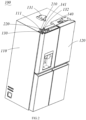
- refrigerator 100 comprises a cabinet 110 and a door 120 for opening and closing the cabinet 110.
- the door 120 can be pivotally connected to the cabinet 110 via a hinge 130, the hinge 130 has a hinge plate fixedly connected to the cabinet 110 and a hinge axis 132 pivotally connected to the door 120.
- the door 110 is provided with a door axis, and the hinge axis 132 is connected to the door axis, so that the door can rotate relative to the cabinet.
- Both the cabinet 110 and the door 120 can be provided with thermal insulation layers to prevent the loss of cold air inside the refrigerator 100.
- the cabinet 110 can comprise an outer shell and an inner liner, with a thermal insulation layer provided between the outer shell and the inner liner.
- the door 120 can comprise a door shell and a door liner, with a thermal insulation layer provided between the door shell and the door liner.
- the thermal insulation layer can be made of foam material.
- the inner liner of the cabinet 110 forms a storage compartment, the storage compartment can comprise a refrigeration compartment and a freezing compartment.
- the door 120 of the refrigeration compartment can be provided with an ice-making compartment and an ice-making door for opening and closing the ice-making compartment.
- the ice-making door is filled with thermal insulation material to isolate the ice-making compartment from the refrigeration compartment.
- the ice-making compartment can be equipped with an ice-making device and an ice storage device.
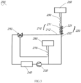
- the refrigerator 100 also comprises a refrigeration system 200.
- the refrigeration system 200 can comprise a compressor 230, a condenser 240, a door capillary tube 250, and a door evaporator 260 connected in sequence.
- the compressor 230 and the condenser 240 can be installed on a cabinet side, such as in a compressor compartment provided on the cabinet side, which can be located at the bottom of the cabinet 110.
- the compressor 230 and the condenser 240 can be installed inside the compressor compartment.
- the door evaporator 260 can be installed inside the door 120. Specifically, the door evaporator 260 can be installed inside the ice-making compartment to supply cold air to the ice-making compartment.
- the cabinet side is also provided with a cabinet evaporator 280 and a cabinet capillary tube 270.
- the cabinet evaporator 280 can supply cold air to the refrigeration compartment and the freezing compartment.
- the cabinet evaporator 280 and the door evaporator 260 can share the compressor 230 and the condenser 240. Specifically, the compressor 230 is connected to the condenser 240 via a refrigerant pipe.
- the condenser 240 is connected to a one-in-two-out solenoid valve 290, which supplies refrigerant to both the door evaporator 260 and the cabinet evaporator 280.
- the refrigerant flowing through the door evaporator 260 and the cabinet evaporator 280 returns to the compressor 230 in the compressor compartment.
- the condenser 240 is connected to the door evaporator 260 via an intake pipe 210, and the door evaporator 260 is connected to the compressor 230 via a return pipe 220.
- the intake pipe 210 can pass through the thermal insulation layer of the cabinet 110 from the compressor compartment and then enter the thermal insulation layer of the door 120 to connect with the door evaporator 260.
- One end of the return pipe 220 is connected to the door evaporator 260 and passes through the thermal insulation layer of the door 120, then enters the thermal insulation layer of the cabinet 110, and finally enters the compressor compartment to connect with the compressor 230.
- a pipe port 111 is provided on the cabinet 110.
- the pipe port 111 can be provided at the top of the cabinet 110.
- the return pipe 220 enters the door shaft on the door side from the thermal insulation layer of the door 120, passes out through the hinge axis 132 on the door side, and then enters the thermal insulation layer of the cabinet 110 from the pipe port 111 on the cabinet 110.
- the refrigerator 100 also comprises a thermally insulated hinge cover plate 131.
- the hinge cover plate 131 at least covers the exposed return pipe 220 between the hinge axis 132 and the pipe port 111.
- the hinge cover plate 131 can be directly installed on the cabinet 110 using screws or other fasteners.
- the hinge cover plate 131 is thermally insulated and covers the part of the return pipe 220 exposed outside the cabinet 110 and the door 120, the return pipe 220 does not directly contact the outside, and therefore, condensation will not occur on the exterior of the low-temperature return pipe 220.
- the hinge cover plate 131 covers the return pipe 220, making the overall appearance more aesthetically pleasing and the structure compact and easy to install and manufacture.
- the hinge cover plate 131 comprises a hinge shell and thermal insulation foam fixed to the inside of the hinge shell.
- the thermal insulation foam can be snap-fitted and fixed inside the hinge shell.
- the hinge cover plate 131 can be directly installed, making the installation process simple.
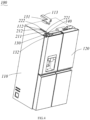
- a pipeline guide box 140 can also be provided on the cabinet 110.
- the pipeline guide box 140 can be provided at the top of the cabinet 110 near the edge of an opening side.
- the pipeline guide box 140 comprises a pipeline guide groove 141 provided close to the hinge 130 side.
- the intake pipe 210 and the return pipe 220 can pass through the pipeline guide groove 141 and then enter the pipe port 111.
- the hinge cover plate 131 covers the pipeline guide groove 140 and abuts against the sidewall of the pipeline guide groove 141.
- the pipeline guide groove 141 can guide and position the pipelines while also limiting the position of the hinge cover plate 131.
- a guide groove for accommodating the return pipe 220 can be provided on the hinge cover plate 131.
- the guide groove can be provided on the thermal insulation foam.
- the door capillary tube 250 can be set inside the door 120. Specifically, the door capillary tube 250 can be set inside the thermal insulation layer of the door 120.
- the condenser 240 is connected to the door capillary tube 250 via a first intake pipe, and the door capillary tube 250 is connected to the door evaporator 260 via a second intake pipe.
- the first intake pipe exits the thermal insulation layer of the cabinet 110 and enters the door shaft of the door 120 from the hinge axis 132 on the door side, and then connects to the door capillary tube 250 inside the thermal insulation layer of the door 120.
- the door capillary tube 250 can also partially extend into the door shaft of the door 120.
- the first intake pipe connects to the door capillary tube 250 inside the door shaft after passing through the hinge axis 132 on the door 120 side.
- the door capillary tube 250 and the return pipe 220 form at least a part of the tube bundle, ensuring heat exchange effectiveness.
- the portion of the first intake pipe disposed between the door 120 and the cabinet 110 is exposed outside of the door 120 and the cabinet 110, but since the door capillary tube 250 is located inside the door 120, the refrigerant flowing through the first intake pipe is at room temperature, so the first intake pipe does not have a condensation problem.
- the intake pipe 210 can pass out from the pipe port 111 on the cabinet 110 and enter the door shaft of the door 120 from the hinge axis 132 on the door side, then enter the thermal insulation layer of the door 120.
- the thermally insulated hinge cover plate 131 can cover the intake pipe 210 between the hinge axis 132 and the pipe port 111.
- the return pipe 220 can comprise a flexible return pipe 221 and a return copper pipe 222 connected to the flexible return pipe 221.
- the intake pipe 210 can comprise a flexible intake pipe 211 and an intake copper pipe 212.
- the flexible intake pipe 211 and the flexible return pipe 221 at least extend from the hinge axis 132 on the door side to the cabinet side, so they do not hinder the opening and closing of the door 120, and the flexible pipes are flexible, not easily damaged by the rotation of the door 120.
- the intake copper pipe 212 and the return copper pipe 222 ensure good heat exchange.
- the intake pipe 210 can comprise an intake copper pipe on the door side and an intake copper pipe 212 on the cabinet side.
- the intake copper pipe on the door side can be embedded in the thermal insulation layer of the door 120.
- Both ends of the flexible intake pipe 211 can be connected to the intake copper pipe on the door side and the intake copper pipe 212 on the cabinet side.
- the flexible intake pipe 211 can enter the door shaft of the door 120 from the hinge axis on the door side and connect to the intake copper pipe inside the door shaft, the intake copper pipe set on the door side, or the flexible intake pipe 211 can directly extend into the thermal insulation layer of the door 120 and connect to the intake copper pipe inside the thermal insulation layer, the intake copper pipe is set on the door side.
- the intake copper pipe 212 on the cabinet side can connect to the condenser 240 inside the compressor compartment, and the intake copper pipe on the door side can connect to the door capillary tube 250.
- the return copper pipe 222 also comprises a return copper pipe 222 on the cabinet side and a return copper pipe on the door side.
- the return copper pipe 222 on the cabinet side connects to the refrigerant inlet of the compressor 230, and the return copper pipe on the door side connects to the refrigerant outlet of the door evaporator 260.
- Both ends of the flexible return pipe 221 can be connected to the intake copper pipe 212 on the cabinet side and the return copper pipe on the door side.
- the flexible return pipe 221 can enter the door shaft of the door 120 from the hinge axis on the door side, and inside the door shaft the flexible return pipe 221 connect to the return copper pipe on the door side.
- the flexible return pipe 221 can also enter the thermal insulation layer of the door 120 after entering the door shaft and connect to the return copper pipe on the door side inside the thermal insulation layer.
- the axis of the pipe port 111 on the cabinet 110 is parallel to the axis of the hinge axis 132.
- the hinge cover plate 131 covers both the hinge axis 132 and the pipe port 111.
- both the return pipe 220 and the intake pipe 210 can pass out from the hinge axis 132 of the door 120 and then enter the interior of the cabinet 110 from the pipe port 111.
- the axis of the pipe port 111 is parallel to the hinge axis 132, which can reduce damage to the return pipe 220 and the intake pipe 210 during the rotation of the door 120.
- the flexible intake pipe 211 and the flexible return pipe 221 both pass out from the hinge axis 132 on the door side and enters into the thermal insulation layer of the cabinet 110 through the pipe port 111, and then enters into the compressor compartment to connect with the intake copper pipe 212 and the return copper pipe 222 inside the compressor compartment, respectively.
- the refrigerator 100 can also be equipped with a water supply device, which can supply water to the ice-making device inside the ice-making compartment.
- the water pipe of the water supply device can also pass out from the thermal insulation layer of the door 120 through the hinge axis 132 on t the door side and enter the thermal insulation layer of the cabinet 110 through the pipe port 111.
- the water pipe, flexible return pipe 221, and flexible intake pipe 211 can form a bundle, which is convenient for installation and manufacturing.
- the interface between the flexible return pipe 221 and the return copper pipe 222 on the cabinet side, and the interface between the flexible intake pipe 211 and the intake copper pipe 212 are both located inside the compressor compartment, eliminating the need for additional connection space on the cabinet 110.
- the hinge cover plate 131 directly covers the area between the hinge axis 132 on the door side and the pipe port 111, achieving anti-condensation for the return pipe 220 with a compact overall structure.
- the cabinet 110 is provided with a pipeline accommodation groove 112 and a thermal insulation cover 113 that closes the pipeline accommodation groove 112.
- the pipe port 111 can be set inside the pipeline accommodation groove 112.
- Both the intake copper pipe 212 and the return copper pipe 222 pass through the thermal insulation layer of the cabinet 110 from the compressor compartment and exit from the pipe port 111 on the cabinet 110, and then connect to the flexible intake pipe 211 and the flexible return pipe 221, respectively.
- the interface between the flexible intake pipe 211 and the intake copper pipe 212, and the interface between the flexible return pipe 221 and the return copper pipe 222 are both located inside the pipeline accommodation groove 112.
- the top of the cabinet 110 is recessed to form the pipeline accommodation groove 112, and the pipe port 111 is set on the sidewall of the pipeline accommodation groove 112.
- the thermal insulation cover 113 and the hinge cover plate 131 can be set separately.
- the flexible return pipe 221 passes into the hinge cover plate 131 from the hinge axis 132 of the door 120, then exits from the hinge cover plate 131 and enters the thermal insulation cover 113.
- the thermal insulation cover 113 and the hinge cover plate 131 together cover the return pipe 220 between the hinge axis 132 on the door side and the pipe port 111.
- the thermal insulation cover1 13 can be a part of the hinge cover plate 131, or the thermal insulation cover 113 can be integrally formed with the hinge cover plate 131, making installation and manufacturing more convenient.
- this configuration can reduce the length of the flexible pipes, lowering production and manufacturing costs, and making installation and manufacturing more convenient.
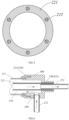
- a heating wire 223 is embedded in the wall of the flexible return pipe 221 at least between the hinge axis 132 on the door side and the pipe port 111 of the cabinet 110.
- the flexible return pipe 221 extends from the hinge axis 132 on the door side to the cabinet side to avoid hindering the opening and closing of the door 120 and to extend the lifespan of the return pipe 220.
- the heating wire 223 can exit from the end surface of one end of the flexible return pipe 221 and connect to a wire harness, the wire harness can enter the interior of the cabinet 110 or the door 120 of the refrigerator 100 and connect to the control board of the refrigerator 100.
- the control board can control the on/off state of the heating wire 223, such as turning on the heating wire 223 only when the compressor 230 is operating to supply refrigerant to the door evaporator 260.
- the portion of the flexible return pipe 221 between the hinge axis 132 on the door side and the pipe port 111 of the cabinet 110 is exposed to the external environment. Since the refrigerant flowing through the flexible return pipe 221 is at a low temperature, the exterior of the flexible return pipe 221 is prone to condensation.
- the heating wire 223 is embedded in the wall of the flexible return pipe 221, occupying a small overall space and being convenient for installation.
- the closure of the flexible return pipe 221 can protect the heating wire 223, and the high toughness of the heating wire 223 can also enhance the toughness of the flexible return pipe 221, increasing its lifespan.
- a heating wire 223 of the same length as the flexible return pipe 221 is embedded in the wall of the flexible return pipe 221, meaning the entire wall of the flexible return pipe 221 has an embedded heating wire 223, making manufacturing more convenient and improving the anti-condensation effect.
- the heating wire 223 comprises multiple resistance wires set at intervals along the circumference of the return pipe 220.
- the resistance wires have good toughness, are not easily broken, and can better enhance the toughness of the flexible return pipe 221.
- the multiple resistance wires are set at intervals along the circumference of the return pipe 220, and the distance between any two adjacent resistance wires can be equal, which can make the heating of the return pipe 220 more uniform, improving the anti-condensation effect.
- FIG. 6 and 7 another embodiment of the present application provides a refrigerator 100.
- the compressor 230 and the condenser 240 of the refrigeration system 200 are installed inside the compressor compartment on the cabinet side, and both the door capillary tube 250 and the door evaporator 260 are installed inside the door 120.
- the refrigerant flowing through the intake pipe 210 between the condenser 240 and the door capillary tube 250 is at room temperature, so the intake pipe 210 will not have a condensation problem.
- both the intake pipe 210 and the return pipe 220 pass out from the hinge axis 132 on the door side and enter the thermal insulation layer of the cabinet 110 through the pipe port 111.
- the intake pipe 210 comprises at least a flexible intake pipe 211 extending from the hinge axis 132 on the door side to the cabinet side.
- the return pipe 220 comprises at least a flexible return pipe 221 extending from the hinge axis 132 on the door side to the cabinet side, and at least the flexible return pipe 221 between the hinge axis 132 on the door side and the pipe port 111 is placed inside the flexible intake pipe 211.
- the refrigerant inside the flexible return pipe 221 between the hinge axis 132 on the door side and the pipe port 111 is at a low temperature. If the flexible return pipe 221 is directly exposed to the external environment, it may produce condensation. Placing the flexible return pipe 221 inside the flexible intake pipe 211 can avoid direct exposure of the flexible return pipe 221 to the external environment, and the exterior of the flexible return pipe 221 is simultaneously wrapped by the flexible intake pipe 211 and the room-temperature refrigerant, so the flexible return pipe 221 will not have condensation.
- the overall structure is compact, does not occupy additional space, and the nesting of the flexible intake pipe 211 and the flexible return pipe 221 does not affect the opening and closing of the door 120 or the lifespan of the pipelines.
- the return pipe 220 comprises a return copper pipe 222 connected to the flexible return pipe 221
- the intake pipe 210 comprises an intake copper pipe 212 connected to the flexible intake pipe 211.
- the flexible return pipe 221 is entirely placed inside the flexible intake pipe 211, which facilitates connection and manufacturing and can enhance the anti-condensation effect.
- the flexible return pipe 221 and the flexible intake pipe 211 can be integrally formed, and support ribs 224 can be set between the flexible return pipe 221 and the flexible intake pipe 211, so that the return pipe 220 is fixed relative to the intake pipe 210.
- the pipelines between the return pipe 220 and the intake pipe 210 are relatively fixed, and the refrigerant from the compressor 230 can smoothly flow through the channel between the intake pipe 210 and the return pipe 220 into the door capillary tube 250, without affecting the refrigeration effect.
- the support ribs 224 can also enhance the stability of the overall structure and the strength of the pipelines, facilitating installation and manufacturing.
- the refrigerator 100 also comprises a diversion connector 300, which connects the flexible intake pipe 211, intake copper pipe 212, flexible return pipe 221, and return copper pipe 222.
- the diversion connector 300 can comprise a diversion connector 300 on the cabinet side and a diversion connector 300 on the door side.
- the refrigerant from the compressor 230 enters the flexible intake pipe 211 through the intake copper pipe 212 via the diversion connector 300, then enters the intake copper pipe on the door side through the diversion connector 300, flows through the door capillary tube 250 and the door evaporator 260, enters the return copper pipe on the door side, passes through the diversion connector 300 on the door side, enters the flexible return pipe 221, passes through the diversion connector 300 on the cabinet side, enters the return copper pipe 222 on the cabinet side, and returns to the compressor 230.
- the diversion connector 300 comprises a fluid chamber 310 and a flexible intake pipe connection part 320 penetrating the fluid chamber 310 and a return pipe connection part 330.
- the end of the flexible intake pipe 211 is connected to the flexible intake pipe connection part 320, and the flexible return pipe 221 passes through the fluid chamber 310 from the flexible intake pipe connection part side and connects to the return pipe connection part 330.
- a space is formed between the flexible return pipe 221 and the sidewall of the fluid chamber 310, the space communicates with the flexible intake pipe 211.
- the diversion connector 300 also comprises an intake copper pipe connection part 340 penetrating the fluid chamber 310, the intake copper pipe 212 is connected to the intake copper pipe connection part 340.
- the fluid chamber 310 is cylindrical, and the inner diameter of the fluid chamber 310 is larger than the outer diameter of the flexible return pipe 221.
- the two ends of the fluid chamber 310 are open and provided with the flexible intake pipe connection part 320 connecting to the flexible intake pipe 211 and the return pipe connection part 330 connecting to the return pipe 220 respectively.
- An opening is formed on the sidewall of the fluid chamber 310 for connecting the intake copper pipe 212 to the intake copper pipe connection part 340.
- the return copper pipe 222 can connect directly to the flexible return pipe 221 or through the return pipe connection part 330.
- Figure 6 shows a schematic diagram of the connection of the diversion connector on the cabinet side, where the arrows represent the direction of the refrigerant flow.
- the refrigerant flows from the intake copper pipe 212 to space between the flexible return pipe 221 and the fluid chamber 310, then flow into between the flexible intake pipe 211 and the flexible return pipe 221 directly.
- the refrigerant in flexible return pipe 221 can flow directly into return copper pipe 222 connected to it.
- the return pipe connection part 330 can include a connecting pipe sleeve 331 placed on one side of fluid chamber 310.
- the flexible return pipe 221 passes through the fluid chamber 310 and is placed inside the connecting pipe sleeve 331.
- the flexible return pipe 221 and the connecting pipe sleeve 331 have an interference fit, and the return copper pipe 222 can be placed inside the flexible return pipe 221 with an interference fit as well.
- both the return copper pipe 222 and the flexible return pipe 221 can be placed inside the connecting pipe sleeve 331, the return copper pipe 222 can be placed inside the flexible return pipe 221.
- the arrangement from outside to inside is the connecting pipe sleeve 331, the flexible return pipe 221, and the return copper pipe 222, and they are interference fit with each other through mechanical compression.
- the flexible intake pipe connection part 320 includes a threaded connecting sleeve 321, one end of the threaded connecting sleeve 321 mating with the flexible intake pipe 211, and the other end threaded to the outer wall of the fluid chamber 310.
- the threaded connecting sleeve 321 can mate with the flexible intake pipe 211 directly or through threaded connection.
- the end of the flexible intake pipe 211 and the threaded connecting sleeve 321 are both mounted on the outer wall of the fluid chamber 310, the outer wall of the fluid chamber 310 is provided with external threads, the threaded connecting sleeve 321 is provided with internal threads.
- the flexible intake pipe 211 can be connected to the diversion connector 300 by the threaded connecting sleeve 321.
- the intake copper pipe connection part 340 can be an opening on a side wall of the fluid cavity 310, and the intake copper pipe 212 can be directly bonded to the intake copper pipe connection part 340 using metal adhesive.
- the diversion connector 300 on the cabinet side is located in the compressor compartment on the cabinet side.
- both the flexible intake pipe 211 and the flexible return pipe 221 pass out from the hinge axis 132 on the door side and through the pipe port 111 on the cabinet 110, then through the thermal insulation layer of the cabinet 110 and into the compressor compartment on the cabinet side.
- the flexible intake pipe 211 and the flexible return pipe 221 connect to the intake copper pipe 212 and the return copper pipe 222 through the diversion connector 300.
- the return pipe 220 is placed inside the intake pipe 210 and directly enters the foam layer through the pipe port 111 on the cabinet 110. There are no parts of the return pipe 220 exposed on the exterior, so there is no risk of condensation, and no additional structures are required.
- the cabinet 110 is provided with a pipeline accommodation groove 112 and a thermal insulation cover 113 that seals the pipeline accommodation groove 112.
- the diversion connector 300 is located inside the pipeline accommodation groove 112.
- Both the intake copper pipe 212 and the return copper pipe 222 pass through the thermal insulation layer of the cabinet 110 from the compressor compartment, enter the pipeline accommodation groove 112 through the pipe port 111, and connect to the diversion connector 300.
- Both the flexible return pipe 221 and the flexible intake pipe 211 extend from the hinge axis 132 on the door side to the cabinet side and connect to the diversion connector 300.
- the length of the flexible return pipe 221 and the flexible intake pipe 211 is reduced, which can lower costs.
- condensation may occur at the diversion connector 300. Therefore, by setting the pipeline accommodation groove 112 on the cabinet 110 and sealing it with the thermal insulation cover 113, and placing the diversion connector 300 inside the pipeline accommodation groove 112, condensation at the diversion connector 300 can be avoided.
Landscapes
- Engineering & Computer Science (AREA)
- Physics & Mathematics (AREA)
- Mechanical Engineering (AREA)
- Thermal Sciences (AREA)
- General Engineering & Computer Science (AREA)
- Chemical & Material Sciences (AREA)
- Combustion & Propulsion (AREA)
- Refrigerator Housings (AREA)
Applications Claiming Priority (2)
| Application Number | Priority Date | Filing Date | Title |
|---|---|---|---|
| CN202111355815.8A CN116136349A (zh) | 2021-11-16 | 2021-11-16 | 冰箱 |
| PCT/CN2022/130926 WO2023088151A1 (zh) | 2021-11-16 | 2022-11-09 | 冰箱 |
Publications (2)
| Publication Number | Publication Date |
|---|---|
| EP4435355A1 true EP4435355A1 (de) | 2024-09-25 |
| EP4435355A4 EP4435355A4 (de) | 2025-02-26 |
Family
ID=86334137
Family Applications (1)
| Application Number | Title | Priority Date | Filing Date |
|---|---|---|---|
| EP22894688.5A Withdrawn EP4435355A4 (de) | 2021-11-16 | 2022-11-09 | Kühlschrank |
Country Status (4)
| Country | Link |
|---|---|
| EP (1) | EP4435355A4 (de) |
| CN (1) | CN116136349A (de) |
| AU (1) | AU2022389259B2 (de) |
| WO (1) | WO2023088151A1 (de) |
Family Cites Families (11)
| Publication number | Priority date | Publication date | Assignee | Title |
|---|---|---|---|---|
| KR20080015341A (ko) * | 2006-08-14 | 2008-02-19 | 삼성전자주식회사 | 냉장고 |
| US8136367B2 (en) * | 2008-12-11 | 2012-03-20 | General Electric Company | Hinge assembly for a refrigerator |
| CN103062978B (zh) * | 2013-01-30 | 2015-07-01 | 合肥美菱股份有限公司 | 一种冰箱防凝露加热控制装置及控制方法 |
| CN204403596U (zh) * | 2014-10-29 | 2015-06-17 | 无锡金顶石油管材配件制造有限公司 | 石油管道 |
| KR101883436B1 (ko) * | 2016-04-11 | 2018-07-31 | 주식회사 대우전자 | 냉장고 |
| CN207778907U (zh) * | 2017-12-22 | 2018-08-28 | 青岛海尔股份有限公司 | 冰箱 |
| CN112944741B (zh) * | 2019-12-09 | 2024-12-20 | 青岛海尔智能技术研发有限公司 | 用于冷水机组的液滴蒸发装置及冷水机组 |
| CN113048693A (zh) * | 2019-12-26 | 2021-06-29 | 青岛海尔电冰箱有限公司 | 冰箱 |
| CN212431447U (zh) * | 2020-05-07 | 2021-01-29 | 青岛海尔智能技术研发有限公司 | 冰箱 |
| CN113623917A (zh) * | 2020-05-07 | 2021-11-09 | 青岛海尔智能技术研发有限公司 | 冰箱 |
| CN113482473A (zh) * | 2021-07-21 | 2021-10-08 | 青岛海尔电冰箱有限公司 | 铰链组件及冰箱 |
-
2021
- 2021-11-16 CN CN202111355815.8A patent/CN116136349A/zh active Pending
-
2022
- 2022-11-09 AU AU2022389259A patent/AU2022389259B2/en active Active
- 2022-11-09 WO PCT/CN2022/130926 patent/WO2023088151A1/zh not_active Ceased
- 2022-11-09 EP EP22894688.5A patent/EP4435355A4/de not_active Withdrawn
Also Published As
| Publication number | Publication date |
|---|---|
| WO2023088151A8 (zh) | 2024-04-18 |
| AU2022389259B2 (en) | 2025-08-28 |
| AU2022389259A1 (en) | 2024-05-30 |
| EP4435355A4 (de) | 2025-02-26 |
| WO2023088151A1 (zh) | 2023-05-25 |
| CN116136349A (zh) | 2023-05-19 |
Similar Documents
| Publication | Publication Date | Title |
|---|---|---|
| US10584916B2 (en) | Water-feed assembly of ice maker in refrigerator and refrigerator | |
| US5743109A (en) | Energy efficient domestic refrigeration system | |
| CN109764599B (zh) | 双系统冰箱 | |
| KR20090006389A (ko) | 냉장고 | |
| CN212431447U (zh) | 冰箱 | |
| EP4435355A1 (de) | Kühlschrank | |
| EP4435356A1 (de) | Kühlschrank | |
| CN108224875A (zh) | 一种卧式无霜双温冷柜 | |
| EP4435357A1 (de) | Kühlschrank | |
| CN201340154Y (zh) | 冰箱 | |
| US11828523B2 (en) | Connector for increasing heat transfer between a refrigerant loop and a refrigerator appliance casing | |
| CN111879051B (zh) | 风道组件及冰箱 | |
| CN219199628U (zh) | 制冷电器 | |
| CN208332806U (zh) | 一种卧式无霜双温冷柜 | |
| CN214039122U (zh) | 冷藏冷冻装置 | |
| CN110285095A (zh) | 蜗壳、制冷系统及具有其的制冷设备 | |
| CN215176326U (zh) | 一种冰箱 | |
| KR100909466B1 (ko) | 냉장고의 급수관 설치구조 | |
| CN114623644A (zh) | 冷藏冷冻装置 | |
| CN116928949B (zh) | 用于冰箱门体送风的风道组件、箱体及冰箱 | |
| CN220354537U (zh) | 阀门及空调器 | |
| CN215176361U (zh) | 一种冰箱风道组件 | |
| CN214039123U (zh) | 冷藏冷冻装置 | |
| CN213657242U (zh) | 一种制冰室的开口结构 | |
| CN120176361A (zh) | 制冷设备 |
Legal Events
| Date | Code | Title | Description |
|---|---|---|---|
| STAA | Information on the status of an ep patent application or granted ep patent |
Free format text: STATUS: THE INTERNATIONAL PUBLICATION HAS BEEN MADE |
|
| PUAI | Public reference made under article 153(3) epc to a published international application that has entered the european phase |
Free format text: ORIGINAL CODE: 0009012 |
|
| STAA | Information on the status of an ep patent application or granted ep patent |
Free format text: STATUS: REQUEST FOR EXAMINATION WAS MADE |
|
| 17P | Request for examination filed |
Effective date: 20240327 |
|
| AK | Designated contracting states |
Kind code of ref document: A1 Designated state(s): AL AT BE BG CH CY CZ DE DK EE ES FI FR GB GR HR HU IE IS IT LI LT LU LV MC ME MK MT NL NO PL PT RO RS SE SI SK SM TR |
|
| REG | Reference to a national code |
Ref country code: DE Ref legal event code: R079 Free format text: PREVIOUS MAIN CLASS: F25D0011020000 Ipc: F25C0005200000 |
|
| DAV | Request for validation of the european patent (deleted) | ||
| DAX | Request for extension of the european patent (deleted) | ||
| A4 | Supplementary search report drawn up and despatched |
Effective date: 20250128 |
|
| RIC1 | Information provided on ipc code assigned before grant |
Ipc: F25D 23/06 20060101ALI20250122BHEP Ipc: F25D 23/02 20060101ALI20250122BHEP Ipc: F25D 23/00 20060101ALI20250122BHEP Ipc: F25D 21/04 20060101ALI20250122BHEP Ipc: F25D 11/02 20060101ALI20250122BHEP Ipc: F25C 5/20 20180101AFI20250122BHEP |
|
| STAA | Information on the status of an ep patent application or granted ep patent |
Free format text: STATUS: THE APPLICATION IS DEEMED TO BE WITHDRAWN |
|
| 18D | Application deemed to be withdrawn |
Effective date: 20250815 |