EP4435162A1 - Fiber structure and fiber-reinforced composite material - Google Patents
Fiber structure and fiber-reinforced composite material Download PDFInfo
- Publication number
- EP4435162A1 EP4435162A1 EP24164103.4A EP24164103A EP4435162A1 EP 4435162 A1 EP4435162 A1 EP 4435162A1 EP 24164103 A EP24164103 A EP 24164103A EP 4435162 A1 EP4435162 A1 EP 4435162A1
- Authority
- EP
- European Patent Office
- Prior art keywords
- fiber
- reinforcing fiber
- fibers
- yarns
- reinforcing
- Prior art date
- Legal status (The legal status is an assumption and is not a legal conclusion. Google has not performed a legal analysis and makes no representation as to the accuracy of the status listed.)
- Granted
Links
Images

Classifications
-
- B—PERFORMING OPERATIONS; TRANSPORTING
- B29—WORKING OF PLASTICS; WORKING OF SUBSTANCES IN A PLASTIC STATE IN GENERAL
- B29C—SHAPING OR JOINING OF PLASTICS; SHAPING OF MATERIAL IN A PLASTIC STATE, NOT OTHERWISE PROVIDED FOR; AFTER-TREATMENT OF THE SHAPED PRODUCTS, e.g. REPAIRING
- B29C70/00—Shaping composites, i.e. plastics material comprising reinforcements, fillers or preformed parts, e.g. inserts
- B29C70/04—Shaping composites, i.e. plastics material comprising reinforcements, fillers or preformed parts, e.g. inserts comprising reinforcements only, e.g. self-reinforcing plastics
- B29C70/06—Fibrous reinforcements only
- B29C70/10—Fibrous reinforcements only characterised by the structure of fibrous reinforcements, e.g. hollow fibres
- B29C70/16—Fibrous reinforcements only characterised by the structure of fibrous reinforcements, e.g. hollow fibres using fibres of substantial or continuous length
- B29C70/20—Fibrous reinforcements only characterised by the structure of fibrous reinforcements, e.g. hollow fibres using fibres of substantial or continuous length oriented in a single direction, e.g. roofing or other parallel fibres
-
- B—PERFORMING OPERATIONS; TRANSPORTING
- B29—WORKING OF PLASTICS; WORKING OF SUBSTANCES IN A PLASTIC STATE IN GENERAL
- B29C—SHAPING OR JOINING OF PLASTICS; SHAPING OF MATERIAL IN A PLASTIC STATE, NOT OTHERWISE PROVIDED FOR; AFTER-TREATMENT OF THE SHAPED PRODUCTS, e.g. REPAIRING
- B29C70/00—Shaping composites, i.e. plastics material comprising reinforcements, fillers or preformed parts, e.g. inserts
- B29C70/04—Shaping composites, i.e. plastics material comprising reinforcements, fillers or preformed parts, e.g. inserts comprising reinforcements only, e.g. self-reinforcing plastics
- B29C70/06—Fibrous reinforcements only
- B29C70/10—Fibrous reinforcements only characterised by the structure of fibrous reinforcements, e.g. hollow fibres
- B29C70/12—Fibrous reinforcements only characterised by the structure of fibrous reinforcements, e.g. hollow fibres using fibres of short length, e.g. in the form of a mat
- B29C70/14—Fibrous reinforcements only characterised by the structure of fibrous reinforcements, e.g. hollow fibres using fibres of short length, e.g. in the form of a mat oriented
-
- D—TEXTILES; PAPER
- D03—WEAVING
- D03D—WOVEN FABRICS; METHODS OF WEAVING; LOOMS
- D03D25/00—Woven fabrics not otherwise provided for
- D03D25/005—Three-dimensional woven fabrics
-
- B—PERFORMING OPERATIONS; TRANSPORTING
- B29—WORKING OF PLASTICS; WORKING OF SUBSTANCES IN A PLASTIC STATE IN GENERAL
- B29C—SHAPING OR JOINING OF PLASTICS; SHAPING OF MATERIAL IN A PLASTIC STATE, NOT OTHERWISE PROVIDED FOR; AFTER-TREATMENT OF THE SHAPED PRODUCTS, e.g. REPAIRING
- B29C70/00—Shaping composites, i.e. plastics material comprising reinforcements, fillers or preformed parts, e.g. inserts
- B29C70/04—Shaping composites, i.e. plastics material comprising reinforcements, fillers or preformed parts, e.g. inserts comprising reinforcements only, e.g. self-reinforcing plastics
- B29C70/06—Fibrous reinforcements only
- B29C70/08—Fibrous reinforcements only comprising combinations of different forms of fibrous reinforcements incorporated in matrix material, forming one or more layers, and with or without non-reinforced layers
- B29C70/081—Combinations of fibres of continuous or substantial length and short fibres
-
- B—PERFORMING OPERATIONS; TRANSPORTING
- B29—WORKING OF PLASTICS; WORKING OF SUBSTANCES IN A PLASTIC STATE IN GENERAL
- B29C—SHAPING OR JOINING OF PLASTICS; SHAPING OF MATERIAL IN A PLASTIC STATE, NOT OTHERWISE PROVIDED FOR; AFTER-TREATMENT OF THE SHAPED PRODUCTS, e.g. REPAIRING
- B29C70/00—Shaping composites, i.e. plastics material comprising reinforcements, fillers or preformed parts, e.g. inserts
- B29C70/04—Shaping composites, i.e. plastics material comprising reinforcements, fillers or preformed parts, e.g. inserts comprising reinforcements only, e.g. self-reinforcing plastics
- B29C70/06—Fibrous reinforcements only
- B29C70/10—Fibrous reinforcements only characterised by the structure of fibrous reinforcements, e.g. hollow fibres
- B29C70/16—Fibrous reinforcements only characterised by the structure of fibrous reinforcements, e.g. hollow fibres using fibres of substantial or continuous length
- B29C70/22—Fibrous reinforcements only characterised by the structure of fibrous reinforcements, e.g. hollow fibres using fibres of substantial or continuous length oriented in at least two directions forming a two-dimensional [2D] structure
- B29C70/228—Fibrous reinforcements only characterised by the structure of fibrous reinforcements, e.g. hollow fibres using fibres of substantial or continuous length oriented in at least two directions forming a two-dimensional [2D] structure the structure being stacked in parallel layers with fibres of adjacent layers crossing at substantial angles
-
- B—PERFORMING OPERATIONS; TRANSPORTING
- B29—WORKING OF PLASTICS; WORKING OF SUBSTANCES IN A PLASTIC STATE IN GENERAL
- B29C—SHAPING OR JOINING OF PLASTICS; SHAPING OF MATERIAL IN A PLASTIC STATE, NOT OTHERWISE PROVIDED FOR; AFTER-TREATMENT OF THE SHAPED PRODUCTS, e.g. REPAIRING
- B29C70/00—Shaping composites, i.e. plastics material comprising reinforcements, fillers or preformed parts, e.g. inserts
- B29C70/04—Shaping composites, i.e. plastics material comprising reinforcements, fillers or preformed parts, e.g. inserts comprising reinforcements only, e.g. self-reinforcing plastics
- B29C70/28—Shaping operations therefor
- B29C70/40—Shaping or impregnating by compression not applied
- B29C70/42—Shaping or impregnating by compression not applied for producing articles of definite length, i.e. discrete articles
- B29C70/46—Shaping or impregnating by compression not applied for producing articles of definite length, i.e. discrete articles using matched moulds, e.g. for deforming sheet moulding compounds [SMC] or prepregs
- B29C70/48—Shaping or impregnating by compression not applied for producing articles of definite length, i.e. discrete articles using matched moulds, e.g. for deforming sheet moulding compounds [SMC] or prepregs and impregnating the reinforcements in the closed mould, e.g. resin transfer moulding [RTM], e.g. by vacuum
-
- B—PERFORMING OPERATIONS; TRANSPORTING
- B29—WORKING OF PLASTICS; WORKING OF SUBSTANCES IN A PLASTIC STATE IN GENERAL
- B29C—SHAPING OR JOINING OF PLASTICS; SHAPING OF MATERIAL IN A PLASTIC STATE, NOT OTHERWISE PROVIDED FOR; AFTER-TREATMENT OF THE SHAPED PRODUCTS, e.g. REPAIRING
- B29C70/00—Shaping composites, i.e. plastics material comprising reinforcements, fillers or preformed parts, e.g. inserts
- B29C70/04—Shaping composites, i.e. plastics material comprising reinforcements, fillers or preformed parts, e.g. inserts comprising reinforcements only, e.g. self-reinforcing plastics
- B29C70/28—Shaping operations therefor
- B29C70/54—Component parts, details or accessories; Auxiliary operations, e.g. feeding or storage of prepregs or SMC after impregnation or during ageing
- B29C70/543—Fixing the position or configuration of fibrous reinforcements before or during moulding
-
- B—PERFORMING OPERATIONS; TRANSPORTING
- B29—WORKING OF PLASTICS; WORKING OF SUBSTANCES IN A PLASTIC STATE IN GENERAL
- B29C—SHAPING OR JOINING OF PLASTICS; SHAPING OF MATERIAL IN A PLASTIC STATE, NOT OTHERWISE PROVIDED FOR; AFTER-TREATMENT OF THE SHAPED PRODUCTS, e.g. REPAIRING
- B29C70/00—Shaping composites, i.e. plastics material comprising reinforcements, fillers or preformed parts, e.g. inserts
- B29C70/04—Shaping composites, i.e. plastics material comprising reinforcements, fillers or preformed parts, e.g. inserts comprising reinforcements only, e.g. self-reinforcing plastics
- B29C70/28—Shaping operations therefor
- B29C70/54—Component parts, details or accessories; Auxiliary operations, e.g. feeding or storage of prepregs or SMC after impregnation or during ageing
- B29C70/546—Measures for feeding or distributing the matrix material in the reinforcing structure
-
- C—CHEMISTRY; METALLURGY
- C08—ORGANIC MACROMOLECULAR COMPOUNDS; THEIR PREPARATION OR CHEMICAL WORKING-UP; COMPOSITIONS BASED THEREON
- C08J—WORKING-UP; GENERAL PROCESSES OF COMPOUNDING; AFTER-TREATMENT NOT COVERED BY SUBCLASSES C08B, C08C, C08F, C08G or C08H
- C08J5/00—Manufacture of articles or shaped materials containing macromolecular substances
- C08J5/24—Impregnating materials with prepolymers which can be polymerised in situ, e.g. manufacture of prepregs
-
- D—TEXTILES; PAPER
- D02—YARNS; MECHANICAL FINISHING OF YARNS OR ROPES; WARPING OR BEAMING
- D02G—CRIMPING OR CURLING FIBRES, FILAMENTS, THREADS, OR YARNS; YARNS OR THREADS
- D02G3/00—Yarns or threads, e.g. fancy yarns; Processes or apparatus for the production thereof, not otherwise provided for
- D02G3/22—Yarns or threads characterised by constructional features, e.g. blending, filament/fibre
- D02G3/36—Cored or coated yarns or threads
-
- D—TEXTILES; PAPER
- D02—YARNS; MECHANICAL FINISHING OF YARNS OR ROPES; WARPING OR BEAMING
- D02G—CRIMPING OR CURLING FIBRES, FILAMENTS, THREADS, OR YARNS; YARNS OR THREADS
- D02G3/00—Yarns or threads, e.g. fancy yarns; Processes or apparatus for the production thereof, not otherwise provided for
- D02G3/22—Yarns or threads characterised by constructional features, e.g. blending, filament/fibre
- D02G3/38—Threads in which fibres, filaments, or yarns are wound with other yarns or filaments, e.g. wrap yarns, i.e. strands of filaments or staple fibres are wrapped by a helically wound binder yarn
-
- D—TEXTILES; PAPER
- D03—WEAVING
- D03D—WOVEN FABRICS; METHODS OF WEAVING; LOOMS
- D03D15/00—Woven fabrics characterised by the material, structure or properties of the fibres, filaments, yarns, threads or other warp or weft elements used
- D03D15/20—Woven fabrics characterised by the material, structure or properties of the fibres, filaments, yarns, threads or other warp or weft elements used characterised by the material of the fibres or filaments constituting the yarns or threads
- D03D15/283—Woven fabrics characterised by the material, structure or properties of the fibres, filaments, yarns, threads or other warp or weft elements used characterised by the material of the fibres or filaments constituting the yarns or threads synthetic polymer-based, e.g. polyamide or polyester fibres
-
- D—TEXTILES; PAPER
- D03—WEAVING
- D03D—WOVEN FABRICS; METHODS OF WEAVING; LOOMS
- D03D15/00—Woven fabrics characterised by the material, structure or properties of the fibres, filaments, yarns, threads or other warp or weft elements used
- D03D15/40—Woven fabrics characterised by the material, structure or properties of the fibres, filaments, yarns, threads or other warp or weft elements used characterised by the structure of the yarns or threads
- D03D15/47—Woven fabrics characterised by the material, structure or properties of the fibres, filaments, yarns, threads or other warp or weft elements used characterised by the structure of the yarns or threads multicomponent, e.g. blended yarns or threads
-
- D—TEXTILES; PAPER
- D03—WEAVING
- D03D—WOVEN FABRICS; METHODS OF WEAVING; LOOMS
- D03D15/00—Woven fabrics characterised by the material, structure or properties of the fibres, filaments, yarns, threads or other warp or weft elements used
- D03D15/50—Woven fabrics characterised by the material, structure or properties of the fibres, filaments, yarns, threads or other warp or weft elements used characterised by the properties of the yarns or threads
-
- B—PERFORMING OPERATIONS; TRANSPORTING
- B29—WORKING OF PLASTICS; WORKING OF SUBSTANCES IN A PLASTIC STATE IN GENERAL
- B29C—SHAPING OR JOINING OF PLASTICS; SHAPING OF MATERIAL IN A PLASTIC STATE, NOT OTHERWISE PROVIDED FOR; AFTER-TREATMENT OF THE SHAPED PRODUCTS, e.g. REPAIRING
- B29C70/00—Shaping composites, i.e. plastics material comprising reinforcements, fillers or preformed parts, e.g. inserts
- B29C70/04—Shaping composites, i.e. plastics material comprising reinforcements, fillers or preformed parts, e.g. inserts comprising reinforcements only, e.g. self-reinforcing plastics
- B29C70/06—Fibrous reinforcements only
- B29C70/10—Fibrous reinforcements only characterised by the structure of fibrous reinforcements, e.g. hollow fibres
- B29C70/16—Fibrous reinforcements only characterised by the structure of fibrous reinforcements, e.g. hollow fibres using fibres of substantial or continuous length
- B29C70/24—Fibrous reinforcements only characterised by the structure of fibrous reinforcements, e.g. hollow fibres using fibres of substantial or continuous length oriented in at least three directions forming a three-dimensional [3D] structure
-
- B—PERFORMING OPERATIONS; TRANSPORTING
- B29—WORKING OF PLASTICS; WORKING OF SUBSTANCES IN A PLASTIC STATE IN GENERAL
- B29C—SHAPING OR JOINING OF PLASTICS; SHAPING OF MATERIAL IN A PLASTIC STATE, NOT OTHERWISE PROVIDED FOR; AFTER-TREATMENT OF THE SHAPED PRODUCTS, e.g. REPAIRING
- B29C70/00—Shaping composites, i.e. plastics material comprising reinforcements, fillers or preformed parts, e.g. inserts
- B29C70/04—Shaping composites, i.e. plastics material comprising reinforcements, fillers or preformed parts, e.g. inserts comprising reinforcements only, e.g. self-reinforcing plastics
- B29C70/28—Shaping operations therefor
- B29C70/40—Shaping or impregnating by compression not applied
- B29C70/50—Shaping or impregnating by compression not applied for producing articles of indefinite length, e.g. prepregs, sheet moulding compounds [SMC] or cross moulding compounds [XMC]
- B29C70/52—Pultrusion, i.e. forming and compressing by continuously pulling through a die
-
- B—PERFORMING OPERATIONS; TRANSPORTING
- B29—WORKING OF PLASTICS; WORKING OF SUBSTANCES IN A PLASTIC STATE IN GENERAL
- B29K—INDEXING SCHEME ASSOCIATED WITH SUBCLASSES B29B, B29C OR B29D, RELATING TO MOULDING MATERIALS OR TO MATERIALS FOR MOULDS, REINFORCEMENTS, FILLERS OR PREFORMED PARTS, e.g. INSERTS
- B29K2105/00—Condition, form or state of moulded material or of the material to be shaped
- B29K2105/26—Scrap or recycled material
-
- D—TEXTILES; PAPER
- D10—INDEXING SCHEME ASSOCIATED WITH SUBLASSES OF SECTION D, RELATING TO TEXTILES
- D10B—INDEXING SCHEME ASSOCIATED WITH SUBLASSES OF SECTION D, RELATING TO TEXTILES
- D10B2505/00—Industrial
- D10B2505/02—Reinforcing materials; Prepregs
Definitions
- a fiber-reinforced composite material is formed of matrix resin as a matrix and a fiber structure as a reinforcement.
- the fiber structure includes reinforcing fiber yarns, which are preferably non-twisted.
- the non-twisted reinforcing fiber yarns are easily arranged in the same fiber orientation, which can suppress a decrease in the strength of the fiber-reinforced composite material.
- Examples of the reinforcing fibers forming the non-twisted reinforcing fiber yarns include regenerated carbon fibers of spun yarns disclosed in Japanese Patent Application Publication No. 2013-519000 .
- the regenerated carbon fibers disclosed in Japanese Patent Application Publication No. 2013-519000 are discontinuous fibers that extend linearly.
- the reinforcing fiber yarns formed of the linearly extending discontinuous fibers need to be maintained in bundle form by a covering yarn wrapping around the bundle of the discontinuous fibers.
- the fiber structure which includes the reinforcing fiber yarns with the covering yarn, serves as a reinforcement, the reinforcement is likely to have a gap between the reinforcing fibers. Accordingly, the fiber-reinforced composite material is likely to have a resin-rich portion between the reinforcing fiber yarns, where only matrix resin is filled.
- the present invention which has been made in light of the above-mentioned problem, is directed to providing a fiber structure and a fiber-reinforced composite material that suppress the generation of a resin-rich portion.
- a fiber structure serving as a reinforcement of a fiber-reinforced composite material that includes matrix resin as a matrix.
- the fiber structure includes a plurality of first reinforcing fiber yarns and a second reinforcing fiber yarn.
- the first reinforcing fiber yarns is each formed of a bundle of fibers including discontinuous fibers made of reinforcing fibers.
- the bundle of fibers is wrapped with a covering yarn.
- the second reinforcing fiber yarn is formed of a bunch of continuous fibers made of reinforcing fibers.
- the fiber structure includes a fiber body formed of the first reinforcing fiber yarns and the second reinforcing fiber yarn arranged alongside and extending in the same direction. The fiber body has a portion in which the second reinforcing fiber yarn is held between and by the first reinforcing fiber yarns.
- the fiber body is formed of the first reinforcing fiber yarns and the second reinforcing fiber yarn arranged alongside and extending in the same direction.
- the fiber body has a portion in which the second reinforcing fiber yarn is held between and by the first reinforcing fiber yarns.
- the continuous fibers are dispersed in the matrix resin filled in a gap between the first reinforcing fiber yarns.
- FIG. 1 schematically illustrates a fiber-reinforced composite material 10 and a fiber structure 20.
- FIG. 2 schematically illustrates the fiber structure 20.
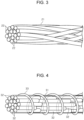
- FIG. 3 schematically illustrates a second reinforcing fiber yarn 21.
- FIG. 4 schematically illustrates a first reinforcing fiber yarn 31.
- the fiber-reinforced composite material 10 includes matrix resin 12 as a matrix and a fiber structure 20 as a reinforcement.
- FIG. 1 schematically illustrates the fiber-reinforced composite material 10 and the matrix resin 12 hatched without a detailed illustration of the outlines of the fiber-reinforced composite material 10 and the fiber structure 20.
- the fiber-reinforced composite material 10 is a square-column prepreg.
- the fiber structure 20 and the fiber-reinforced composite material 10 may have a shape, such an H-shaped columnar cross section, a U-shaped columnar cross section, or a tubular-shaped cross section.
- the matrix resin 12 is epoxy resin, which is thermosetting resin.
- the matrix resin 12 does not have to be epoxy resin, and may be thermosetting resin, such as vinylester resin, unsaturated polyester resin, or phenolic resin, or thermoplastic resin, such as polyamide, polybutylene terephthalate, polycarbonate, polyethylene, polypropylene, polyimide resin, or acrylonitrile-butadiene-styrene (ABS) resin.
- thermosetting resin such as vinylester resin, unsaturated polyester resin, or phenolic resin
- thermoplastic resin such as polyamide, polybutylene terephthalate, polycarbonate, polyethylene, polypropylene, polyimide resin, or acrylonitrile-butadiene-styrene (ABS) resin.
- the fiber structure 20 includes a plurality of first reinforcing fiber yarns 31 and a plurality of second reinforcing fiber yarns 21.
- FIGS. 1 and 2 schematically illustrate the fiber structure 20 without a detailed illustration of the first reinforcing fiber yarns 31 and the second reinforcing fiber yarns 21.
- the fiber structure 20 is a unidirectional fabric.
- the fiber structure 20 is formed of the first reinforcing fiber yarns 31 and the second reinforcing fiber yarns 21 arranged alongside so that the first reinforcing fiber yarns 31 and the second reinforcing fiber yarns 21 extend in the same direction.
- the fiber structure 20 includes a fiber body formed of the first reinforcing fiber yarns 31 and the second reinforcing fiber yarns 21 arranged alongside so that the first reinforcing fiber yarns 31 and the second reinforcing fiber yarns 21 extend in the same direction. According to the present embodiment, the whole fiber structure 20 serves as the fiber body.
- each of the second reinforcing fiber yarns 21 is formed of the bunched continuous fibers 22 made of reinforcing fibers.
- the continuous fibers 22 extend linearly and have rectilinearity.
- the continuous fibers 22 are filaments.
- the continuous fibers 22 extend linearly and have rectilinearity, but are partially gently curved for a productional reason. That is, the continuous fibers 22 have rectilinearity, but have a slightly curved or twisted portion.
- the continuous fibers 22 may be formed of organic or inorganic fibers, or mixed fibers formed of different types of organic fibers, different types of inorganic fibers, or a mix of organic and inorganic fibers.
- organic fibers include acrylic fibers, nylon fibers, polyester fibers, aramid fibers, poly-p-phenylenebenzobisoxazole fibers, and ultra-high molecular weight polyethylene fibers.
- inorganic fibers include carbon fibers, glass fibers, and ceramic fibers. According to the present embodiment, the continuous fibers 22 are filaments of inorganic carbon fibers.
- each of the first reinforcing fiber yarns 31 is formed of a bundle of fibers including the discontinuous fibers 32 made of reinforcing fibers, and the fiber bundle including the discontinuous fibers 32 is helically wrapped with a covering yarn 33.
- the covering yarn 33 maintains the bundled discontinuous fibers 32 in yarn form.
- the discontinuous fibers 32 are staple fibers.
- the discontinuous fibers 32 are formed of cut filaments.
- the discontinuous fibers 32 are shorter than the continuous fibers 22 of the second reinforcing fiber yarn 21.
- the discontinuous fibers 32 may be formed of organic or inorganic fibers, or mixed fibers formed of different types of organic fibers, different types of inorganic fibers, or a mix of organic and inorganic fibers.
- the organic fibers include acrylic fibers, nylon fibers, polyester fibers, aramid fibers, poly-p-phenylenebenzobisoxazole fibers, and ultra-high molecular weight polyethylene fibers.
- the inorganic fibers include carbon fibers, glass fibers, and ceramic fibers.
- the discontinuous fibers 32 are made of regenerated carbon fibers as regenerated fibers.
- the discontinuous fibers 32 are fibers, such as tow or thrum produced when multiaxial fabrics or woven fabric are trimmed.
- the discontinuous fibers 32 extend linearly and have rectilinearity.
- the discontinuous fibers 32 are untwisted.
- the first reinforcing fiber yarn 31 maintained in yarn form by the covering yarn 33 has an approximate circular cross section.
- the first reinforcing fiber yarn 31 is formed of the discontinuous fibers 32 arranged in the same fiber orientation.
- the covering yarn 33 is made of organic fibers.
- the organic fibers as the material of the covering yarn 33 should have a melting point at which the covering yarn 33 does not melt when the fiber structure 20 is heated during the manufacture of the fiber-reinforced composite material 10.
- an axial direction L of the fiber structure 20 corresponds to the extending direction of the first reinforcing fiber yarns 31 and the second reinforcing fiber yarns 21 in the unidirectional fabric. Accordingly, the continuous fibers 22 of the second reinforcing fiber yarns 21 and the discontinuous fibers 32 of the first reinforcing fiber yarns 31 extend linearly in the axial direction L of the fiber structure 20, and have rectilinearity.
- the fiber structure 20 has a rectangular cross section that is perpendicular to the axial direction L. In cross section, the fiber structure 20 is a quadrilateral with two pairs of parallel sides.
- One of the pairs of parallel sides extends in a first direction X, and the other of the pairs of parallel sides extends in a second direction Y.
- the first direction X is perpendicular to the second direction Y.
- the first direction X and the second direction Y are perpendicular to the axial direction L.
- the ratio of the first reinforcing fiber yarns 31 and the second reinforcing fiber yarns 21 per unit area of the fiber structure 20 is determined arbitrary. If the fiber structure 20 serving as the reinforcement needs more strength in the axial direction L, the first reinforcing fiber yarns 31 need to be larger than the second reinforcing fiber yarns 21 in the ratio of the first reinforcing fiber yarns 31 to the second reinforcing fiber yarns 21 per unit area.
- the discontinuous fibers 32 of the first reinforcing fiber yarns 31 are regenerated carbon fibers.
- the first reinforcing fiber yarns 31 are larger than the second reinforcing fiber yarns 21 in the ratio of the first reinforcing fiber yarns 31 to the second reinforcing fiber yarns 21 per unit area.
- the first reinforcing fiber yarns 31 and the second reinforcing fiber yarns 21 are randomly arranged in the first direction X and the second direction Y.
- the first reinforcing fiber yarns 31 and the second reinforcing fiber yarns 21 may be arranged alternately in the first direction X and the second direction Y.
- the second reinforcing fiber yarns 21 are adjacent to the first reinforcing fiber yarns 31 in another direction other than the first direction X and the second direction Y.
- the fiber structure 20, which serves as the fiber body, has a plurality of portions in which a single second reinforcing fiber yarn 21 is held between and by two first reinforcing fiber yarns 31 in the first direction X, in the second direction Y, or in another direction. That is, the second reinforcing fiber yarns 21 are held between and by the first reinforcing fiber yarns 31 from various directions in the fiber structure 20.
- the fiber structure 20 is the reinforcement formed of a prepreg impregnated with the matrix resin 12. Accordingly, the fiber-reinforced composite material 10 is a prepreg.
- the fiber-reinforced composite material 10 is produced by pultrusion molding equipment 40.
- the fiber structure 20 is produced in the manufacturing process of the fiber-reinforced composite material 10.
- the pultrusion molding equipment 40 includes a feeding device 41, an impregnation bath 42, a press 43, a heating die 44, a puller 45, and a cutter 46.
- the feeding device 41 includes a feeder 41a for feeding the second reinforcing fiber yarns 21 and a feeder 41b for feeding the first reinforcing fiber yarns 31.
- the feeding device 41 feeds the first reinforcing fiber yarns 31 and the second reinforcing fiber yarns 21 in the same direction to produce the fiber structure 20.
- the first reinforcing fiber yarns 31 and the second reinforcing fiber yarns 21 are pulled by the puller 45.
- the first reinforcing fiber yarns 31 and the second reinforcing fiber yarns 21 are pulled by the puller 45, so that the first reinforcing fiber yarns 31 and the second reinforcing fiber yarns 21 are fed from the feeding device 41.
- the first reinforcing fiber yarns 31 and the second reinforcing fiber yarns 21 are fed from the feeding device 41, the first reinforcing fiber yarns 31 and the second reinforcing fiber yarns 21 are randomly arranged in the first direction X and the second direction Y.
- the first reinforcing fiber yarns 31 and the second reinforcing fiber yarns 21 may be alternately arranged in the first direction X and the second direction Y.
- first reinforcing fiber yarns 31 and the second reinforcing fiber yarns 21 are alternately arranged in the first direction X and the second direction Y and fed, the first reinforcing fiber yarns 31 and the second reinforcing fiber yarns 21 are mixed so as to be randomly arranged before reaching the impregnation bath 42.
- the first reinforcing fiber yarns 31 and the second reinforcing fiber yarns 21 fed from the feeding device 41 are bunched together. That is, the first reinforcing fiber yarns 31 and the second reinforcing fiber yarns 21 are fed by the feeding device 41 such that the first reinforcing fiber yarns 31 and the second reinforcing fiber yarns 21 arranged alongside and extend in the same direction to form the fiber structure 20 as the fiber body.
- the fiber body including the first reinforcing fiber yarns 31 and the second reinforcing fiber yarns 21 fed from the feeding device 41 serves as the fiber structure 20.
- FIG. 5 the pultrusion molding equipment 40 and the fiber structure 20 are schematically illustrated.
- the fiber structure 20 has a gap between any two first reinforcing fiber yarns 31 adjacent in the first direction X, in the second direction Y, or in another direction.
- a gap is also formed between any two second reinforcing fiber yarns 21 adjacent in the first direction X, in the second direction Y, or in another direction.
- a gap is formed between the second reinforcing fiber yarn 21 and the first reinforcing fiber yarn 31 adjacent in the first direction X, in the second direction Y, or in another direction.
- the matrix resin 12 in a liquid state is stored in the impregnation bath 42.
- the matrix resin 12 stored in the impregnation bath 42 is high-temperature molten resin.
- the matrix resin 12 permeates the fiber structure 20 fed from the feeding device 41.
- the fiber structure 20 continuously passes through the impregnation bath 42 in the extending direction of the fiber body including the first reinforcing fiber yarns 31 and the second reinforcing fiber yarns 21.
- the first reinforcing fiber yarns 31 and the second reinforcing fiber yarns 21 of the fiber structure 20 are impregnated with the matrix resin 12, so that the whole fiber structure 20 is impregnated with the matrix resin 12.
- the matrix resin 12 enters the gap between the adjacent second reinforcing fiber yarns 21, the gap between the adjacent first reinforcing fiber yarns 31, and the gap between the first reinforcing fiber yarn 31 and the second reinforcing fiber yarn 21 adjacent to each other.
- the whole surface of the fiber structure 20 is coated by the matrix resin 12. That is, the gaps in the fiber structure 20 are filled with the matrix resin 12.
- the fiber structure 20 impregnated with the matrix resin 12 is expressed by the press 43. Accordingly, the whole fiber structure 20 is pressed in the second direction Y, so that the first reinforcing fiber yarns 31 and the second reinforcing fiber yarns 21 are pressed in the second direction Y.
- the expression of the fiber structure 20 by the press 43 removes excess matrix resin 12 from the fiber structure 20.
- each second reinforcing fiber yarn 21 of the fiber structure 20 presses the fiber structure 20 causes each second reinforcing fiber yarn 21 of the fiber structure 20 to become deformed such that a gap between the adjacent continuous fibers 22 increases. This loosens the bunched continuous fibers 22 of the second reinforcing fiber yarn 21.
- the continuous fibers 22 are dispersed into the matrix resin 12 between the adjacent first reinforcing fiber yarns 31. In such a way, the fiber-reinforced composite material 10 is produced.
- the heating die 44 heats the fiber structure 20 impregnated with the matrix resin 12, i.e., the fiber-reinforced composite material 10. That is, the matrix resin 12 in the fiber-reinforced composite material 10 is thermally cured by the heating die 44. The fiber-reinforced composite material 10 is then pulled by the puller 45, and cut by the cutter 46 to a desired length.
- the pressed first reinforcing fiber yarn 31 has a slightly flattened shape, but the discontinuous fibers 32 are maintained in bundle form by the covering yarn 33.
- the discontinuous fibers 32 of the pressed first reinforcing fiber yarn 31 are slightly deformed, but still extend almost linearly. Accordingly, the first reinforcing fiber yarn 31 enhances the strength of the fiber-reinforced composite material 10.
- the continuous fibers 22 of the second reinforcing fiber yarn 21 are not bundled by the covering yarn 33 unlike the discontinuous fibers 32 of the first reinforcing fiber yarn 31. Accordingly, the pressed second reinforcing fiber yarn 21 becomes significantly deformed. Pressing the second reinforcing fiber yarn 21 causes the continuous fibers 22 of the second reinforcing fiber yarn 21 to move randomly so as to increase a gap between the continuous fibers 22. Accordingly, the bunched continuous fibers 22 of the second reinforcing fiber yarn 21 more loosen as compared with the bunched continuous fibers 22 before pressing.
- the matrix resin 12 enters the gaps between the adjacent first reinforcing fiber yarns 31.
- the continuous fibers 22 of the second reinforcing fiber yarns 21 are dispersed in the gaps between the adjacent first reinforcing fiber yarns 31 in the various directions, as previously described. Accordingly, the continuous fibers 22 of the second reinforcing fiber yarns 21 are dispersed in the matrix resin 12 between the first reinforcing fiber yarns 31. This suppresses the generation of a resin-rich portion formed of the matrix resin 12 only.
- the dispersed continuous fibers 22 extend almost linearly. Accordingly, the continuous fibers 22 enhance the strength of the fiber-reinforced composite material 10.
- the first embodiment achieves the following effects.
- a fiber-reinforced composite material 50 includes a fiber structure 60.
- the fiber structure 60 is a plurality of fabrics each including a warp layer 65 and a plurality of weft layers 66.
- the warp layer 65 includes a plurality of warp yarns 61, and the weft layers 66 each include a plurality of weft yarns 62.
- the fiber structure 60 is formed of two fabrics laminated with threads 64 in a laminating direction.
- Each of the two fabrics includes a single warp layer 65 and two weft layers 66.
- the warp layer 65 is held between the weft layers 66.
- the warp layer 65 is formed of the warp yarns 61 arranged such that the warp yarns 61 extend in the same direction.
- the weft layers 66 are each formed of the weft yarns 62 arranged such that the weft yarns 62 extend in the same direction.
- the extending direction of the warp yarns 61 intersects the extending direction of the weft yarns 62.
- Each of the warp yarns 61 includes the first reinforcing fiber yarns 31 and the second reinforcing fiber yarns 21.
- the warp layer 65 has a plurality of portions in which two second reinforcing fiber yarns 21 are held between and by the first reinforcing fiber yarns 31 and a plurality of portions in which a single second reinforcing fiber yarn 21 is held between and by the first reinforcing fiber yarns 31.
- the arrangement of the second reinforcing fiber yarns 21 and the first reinforcing fiber yarns 31 may be modified as necessary.
- the first reinforcing fiber yarns 31 and the second reinforcing fiber yarns 21 may be arranged alternately.
- the warp layers 65 include the first reinforcing fiber yarns 31 and the second reinforcing fiber yarns 21 as the warp yarns 61, and serve as the fiber body of the present invention. Accordingly, the fiber structure 60 includes the fiber body of the present invention.
- the weft layers 66 include the first reinforcing fiber yarns 31 only.
- the weft layers 66 are each formed of the weft yarns 62 arranged such that the weft yarns 62 extend in the same direction.
- the threads 64 may be any threads. The threads 64 extend in the laminating direction of the warp layers 65 and the weft layers 66 and are folded back at the outermost weft layer 66 of the fiber structure 60.
- the warp yarns 61 are slightly separated from each other by the threads 64 at locations where the threads 64 extend in the laminating direction.
- each of the threads 64 extending in the laminating direction is disposed between the adjacent second reinforcing fiber yarns 21.
- the adjacent second reinforcing fiber yarns 21 are separated from each other by the corresponding thread 64.
- the fiber-reinforced composite material 50 is formed by the Resin Transfer Molding (RTM) method.
- the fiber structure 60 is placed in a molding die 70, and the molding die 70 is filled with the matrix resin 12 to produce the fiber-reinforced composite material 50.
- the fiber structure 60 is pressed by a fill pressure of the matrix resin 12 in the molding die 70.
- the fiber structure 60 is impregnated with the matrix resin 12 in the molding die 70.
- the matrix resin 12 permeates the first reinforcing fiber yarns 31 and the second reinforcing fiber yarns 21 of the warp layers 65 and the weft layers 66 of the fiber structure 60, thereby permeating the whole fiber structure 60.
- the matrix resin 12 enters the gap between the second reinforcing fiber yarns 21 adjacent to each other and the gap between the second reinforcing fiber yarn 21 and the first reinforcing fiber yarn 31 adjacent to each other.
- the matrix resin 12 enters a gap between the weft yarns 62 adjacent to each other.
- each of the first reinforcing fiber yarns 31 pressed by the fill pressure of the matrix resin 12 has a slightly flattened shape, but the discontinuous fibers 32 are maintained in bundle form by the covering yarn 33.
- the discontinuous fibers 32 of the first reinforcing fiber yarn 31 pressed by the fill pressure are slightly deformed, but still extend almost linearly. Accordingly, the first reinforcing fiber yarn 31 enhances the strength of the fiber-reinforced composite material 50.
- the continuous fibers 22 of the second reinforcing fiber yarn 21 are not bundled by the covering yarn 33 unlike the discontinuous fibers 32 of the first reinforcing fiber yarn 31. Accordingly, the second reinforcing fiber yarn 21 becomes significantly deformed by the fill pressure.
- the fill pressure causes the continuous fibers 22 of the second reinforcing fiber yarn 21 to move randomly so as to increase a gap between the continuous fibers 22. Accordingly, the bunched continuous fibers 22 of the second reinforcing fiber yarn 21 more loosen as compared with the bunched continuous fibers 22 before the filling of the matrix resin 12.
- the continuous fibers 22 of the second reinforcing fiber yarn 21 are dispersed between the adjacent first reinforcing fiber yarns 31 in the warp layer 65.
- the matrix resin 12 enters each gap formed between the adjacent first reinforcing fiber yarns 31 in the warp layer 65.
- the continuous fibers 22 of the second reinforcing fiber yarns 21 are dispersed in the gaps between the adjacent first reinforcing fiber yarns 31, as previously described. Accordingly, the continuous fibers 22 of the second reinforcing fiber yarns 21 are dispersed in the matrix resin 12 between the first reinforcing fiber yarns 31. This suppresses the generation of a resin-rich portion formed of the matrix resin 12 only in the warp layer 65.
- the second embodiment achieves the following effects.
- the fiber structure and the fiber-reinforced composite material according to the embodiments may be modified as described below.
- the embodiments may be combined with the following modifications within technically consistent range.
- the fiber structure (20, 60) includes a fiber body formed of the first reinforcing fiber yarns (31) and the second reinforcing fiber yarn (21) arranged alongside and extending in the same direction.
- the fiber body has a portion in which the second reinforcing fiber yarn (21) is held between and by the first reinforcing fiber yarns (31).
Landscapes
- Engineering & Computer Science (AREA)
- Chemical & Material Sciences (AREA)
- Textile Engineering (AREA)
- Mechanical Engineering (AREA)
- Composite Materials (AREA)
- Materials Engineering (AREA)
- Manufacturing & Machinery (AREA)
- Polymers & Plastics (AREA)
- Organic Chemistry (AREA)
- Medicinal Chemistry (AREA)
- Chemical Kinetics & Catalysis (AREA)
- Health & Medical Sciences (AREA)
- Reinforced Plastic Materials (AREA)
- Yarns And Mechanical Finishing Of Yarns Or Ropes (AREA)
- Woven Fabrics (AREA)
Abstract
Description
- The present invention relates to a fiber structure and a fiber-reinforced composite material.
- A fiber-reinforced composite material is formed of matrix resin as a matrix and a fiber structure as a reinforcement. The fiber structure includes reinforcing fiber yarns, which are preferably non-twisted. The non-twisted reinforcing fiber yarns are easily arranged in the same fiber orientation, which can suppress a decrease in the strength of the fiber-reinforced composite material. Examples of the reinforcing fibers forming the non-twisted reinforcing fiber yarns include regenerated carbon fibers of spun yarns disclosed in
Japanese Patent Application Publication No. 2013-519000 Japanese Patent Application Publication No. 2013-519000 - The reinforcing fiber yarns formed of the linearly extending discontinuous fibers need to be maintained in bundle form by a covering yarn wrapping around the bundle of the discontinuous fibers. The fiber structure, which includes the reinforcing fiber yarns with the covering yarn, serves as a reinforcement, the reinforcement is likely to have a gap between the reinforcing fibers. Accordingly, the fiber-reinforced composite material is likely to have a resin-rich portion between the reinforcing fiber yarns, where only matrix resin is filled.
- The present invention, which has been made in light of the above-mentioned problem, is directed to providing a fiber structure and a fiber-reinforced composite material that suppress the generation of a resin-rich portion.
- In accordance with an aspect of the present invention, there is provided a fiber structure serving as a reinforcement of a fiber-reinforced composite material that includes matrix resin as a matrix. The fiber structure includes a plurality of first reinforcing fiber yarns and a second reinforcing fiber yarn. The first reinforcing fiber yarns is each formed of a bundle of fibers including discontinuous fibers made of reinforcing fibers. The bundle of fibers is wrapped with a covering yarn. The second reinforcing fiber yarn is formed of a bunch of continuous fibers made of reinforcing fibers. The fiber structure includes a fiber body formed of the first reinforcing fiber yarns and the second reinforcing fiber yarn arranged alongside and extending in the same direction. The fiber body has a portion in which the second reinforcing fiber yarn is held between and by the first reinforcing fiber yarns.
- In accordance with another aspect of the present invention, there is provided a fiber-reinforced composite material. The fiber-reinforced composite material includes matrix resin as a matrix; and a fiber structure as a reinforcement. The fiber structure includes: a plurality of first reinforcing fiber yarns; a second reinforcing fiber yarn; and a fiber body. The first reinforcing fiber yarns is each formed of a bundle of fibers including discontinuous fibers made of reinforcing fibers. The bundle of fibers is wrapped with a covering yarn. The second reinforcing fiber yarn is formed of a bunch of continuous fibers made of reinforcing fibers. The fiber body is formed of the first reinforcing fiber yarns and the second reinforcing fiber yarn arranged alongside and extending in the same direction. The fiber body has a portion in which the second reinforcing fiber yarn is held between and by the first reinforcing fiber yarns. The continuous fibers are dispersed in the matrix resin filled in a gap between the first reinforcing fiber yarns.
- Other aspects and advantages of the invention will become apparent from the following description, taken in conjunction with the accompanying drawings, illustrating by way of example the principles of the invention.
- The invention, together with objects and advantages thereof, may best be understood by reference to the following description of the embodiments together with the accompanying drawings in which:
-
FIG. 1 is a schematic cross-sectional view of a fiber-reinforced composite material according to a first embodiment; -
FIG. 2 is a schematic cross-sectional view of a fiber structure according to the first embodiment; -
FIG. 3 is a schematic view of a second reinforcing fiber yarn; -
FIG. 4 is a schematic view of a first reinforcing fiber yarn; -
FIG. 5 is a schematic view of pultrusion molding equipment; -
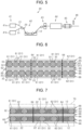
FIG. 6 is a schematic cross-sectional view of a fiber structure according to a second embodiment; and -
FIG. 7 is a schematic cross-sectional view of a fiber-reinforced composite material according to the second embodiment. - The following will describe a fiber structure and a fiber-reinforced composite material according to a first embodiment with reference to accompanying
FIGS. 1 to 5 .FIG. 1 schematically illustrates a fiber-reinforcedcomposite material 10 and afiber structure 20.FIG. 2 schematically illustrates thefiber structure 20.FIG. 3 schematically illustrates a second reinforcingfiber yarn 21.FIG. 4 schematically illustrates a first reinforcingfiber yarn 31. - As illustrated in
FIG. 1 , the fiber-reinforcedcomposite material 10 includesmatrix resin 12 as a matrix and afiber structure 20 as a reinforcement. -
FIG. 1 schematically illustrates the fiber-reinforcedcomposite material 10 and thematrix resin 12 hatched without a detailed illustration of the outlines of the fiber-reinforcedcomposite material 10 and thefiber structure 20. - The fiber-reinforced
composite material 10 is a square-column prepreg. Thefiber structure 20 and the fiber-reinforcedcomposite material 10 may have a shape, such an H-shaped columnar cross section, a U-shaped columnar cross section, or a tubular-shaped cross section. According to the present embodiment, thematrix resin 12 is epoxy resin, which is thermosetting resin. However, thematrix resin 12 does not have to be epoxy resin, and may be thermosetting resin, such as vinylester resin, unsaturated polyester resin, or phenolic resin, or thermoplastic resin, such as polyamide, polybutylene terephthalate, polycarbonate, polyethylene, polypropylene, polyimide resin, or acrylonitrile-butadiene-styrene (ABS) resin. - As illustrated in
FIG. 2 , thefiber structure 20 includes a plurality of first reinforcingfiber yarns 31 and a plurality of second reinforcingfiber yarns 21.FIGS. 1 and 2 schematically illustrate thefiber structure 20 without a detailed illustration of the first reinforcingfiber yarns 31 and the second reinforcingfiber yarns 21. Thefiber structure 20 is a unidirectional fabric. Thefiber structure 20 is formed of the first reinforcingfiber yarns 31 and the second reinforcingfiber yarns 21 arranged alongside so that the first reinforcingfiber yarns 31 and the second reinforcingfiber yarns 21 extend in the same direction. Thefiber structure 20 includes a fiber body formed of the first reinforcingfiber yarns 31 and the second reinforcingfiber yarns 21 arranged alongside so that the first reinforcingfiber yarns 31 and the second reinforcingfiber yarns 21 extend in the same direction. According to the present embodiment, thewhole fiber structure 20 serves as the fiber body. - As illustrated in
FIG. 3 , each of the second reinforcingfiber yarns 21 is formed of the bunchedcontinuous fibers 22 made of reinforcing fibers. Thecontinuous fibers 22 extend linearly and have rectilinearity. Thecontinuous fibers 22 are filaments. Thecontinuous fibers 22 extend linearly and have rectilinearity, but are partially gently curved for a productional reason. That is, thecontinuous fibers 22 have rectilinearity, but have a slightly curved or twisted portion. - Since the second reinforcing
fiber yarn 21 is formed of a bunch of the linearly extendingcontinuous fibers 22, the bunch of thecontinuous fibers 22 is slightly twisted to be maintained in yarn form. Thecontinuous fibers 22 may be formed of organic or inorganic fibers, or mixed fibers formed of different types of organic fibers, different types of inorganic fibers, or a mix of organic and inorganic fibers. Examples of the organic fibers include acrylic fibers, nylon fibers, polyester fibers, aramid fibers, poly-p-phenylenebenzobisoxazole fibers, and ultra-high molecular weight polyethylene fibers. Examples of the inorganic fibers include carbon fibers, glass fibers, and ceramic fibers. According to the present embodiment, thecontinuous fibers 22 are filaments of inorganic carbon fibers. - As illustrated in
FIG. 4 , each of the first reinforcingfiber yarns 31 is formed of a bundle of fibers including thediscontinuous fibers 32 made of reinforcing fibers, and the fiber bundle including thediscontinuous fibers 32 is helically wrapped with a coveringyarn 33. The coveringyarn 33 maintains the bundleddiscontinuous fibers 32 in yarn form. - The
discontinuous fibers 32 are staple fibers. Thediscontinuous fibers 32 are formed of cut filaments. Thediscontinuous fibers 32 are shorter than thecontinuous fibers 22 of the second reinforcingfiber yarn 21. Thediscontinuous fibers 32 may be formed of organic or inorganic fibers, or mixed fibers formed of different types of organic fibers, different types of inorganic fibers, or a mix of organic and inorganic fibers. Examples of the organic fibers include acrylic fibers, nylon fibers, polyester fibers, aramid fibers, poly-p-phenylenebenzobisoxazole fibers, and ultra-high molecular weight polyethylene fibers. Examples of the inorganic fibers include carbon fibers, glass fibers, and ceramic fibers. - According to the present embodiment, the
discontinuous fibers 32 are made of regenerated carbon fibers as regenerated fibers. Thediscontinuous fibers 32 are fibers, such as tow or thrum produced when multiaxial fabrics or woven fabric are trimmed. Thediscontinuous fibers 32 extend linearly and have rectilinearity. Thediscontinuous fibers 32 are untwisted. The first reinforcingfiber yarn 31 maintained in yarn form by the coveringyarn 33 has an approximate circular cross section. The first reinforcingfiber yarn 31 is formed of thediscontinuous fibers 32 arranged in the same fiber orientation. - The covering
yarn 33 is made of organic fibers. The organic fibers as the material of the coveringyarn 33 should have a melting point at which the coveringyarn 33 does not melt when thefiber structure 20 is heated during the manufacture of the fiber-reinforcedcomposite material 10. - As illustrated in
FIG. 2 , an axial direction L of thefiber structure 20 corresponds to the extending direction of the first reinforcingfiber yarns 31 and the second reinforcingfiber yarns 21 in the unidirectional fabric. Accordingly, thecontinuous fibers 22 of the second reinforcingfiber yarns 21 and thediscontinuous fibers 32 of the first reinforcingfiber yarns 31 extend linearly in the axial direction L of thefiber structure 20, and have rectilinearity. Thefiber structure 20 has a rectangular cross section that is perpendicular to the axial direction L. In cross section, thefiber structure 20 is a quadrilateral with two pairs of parallel sides. One of the pairs of parallel sides extends in a first direction X, and the other of the pairs of parallel sides extends in a second direction Y. The first direction X is perpendicular to the second direction Y. The first direction X and the second direction Y are perpendicular to the axial direction L. - The ratio of the first reinforcing
fiber yarns 31 and the second reinforcingfiber yarns 21 per unit area of thefiber structure 20 is determined arbitrary. If thefiber structure 20 serving as the reinforcement needs more strength in the axial direction L, the first reinforcingfiber yarns 31 need to be larger than the second reinforcingfiber yarns 21 in the ratio of the first reinforcingfiber yarns 31 to the second reinforcingfiber yarns 21 per unit area. Thediscontinuous fibers 32 of the first reinforcingfiber yarns 31 are regenerated carbon fibers. From the standpoint of utilization of regenerated carbon fibers, it is desirable that the first reinforcingfiber yarns 31 are larger than the second reinforcingfiber yarns 21 in the ratio of the first reinforcingfiber yarns 31 to the second reinforcingfiber yarns 21 per unit area. - In the
fiber structure 20, the first reinforcingfiber yarns 31 and the second reinforcingfiber yarns 21 are randomly arranged in the first direction X and the second direction Y. The first reinforcingfiber yarns 31 and the second reinforcingfiber yarns 21 may be arranged alternately in the first direction X and the second direction Y. In thefiber structure 20, the second reinforcingfiber yarns 21 are adjacent to the first reinforcingfiber yarns 31 in another direction other than the first direction X and the second direction Y. Thefiber structure 20, which serves as the fiber body, has a plurality of portions in which a single second reinforcingfiber yarn 21 is held between and by two first reinforcingfiber yarns 31 in the first direction X, in the second direction Y, or in another direction. That is, the second reinforcingfiber yarns 21 are held between and by the first reinforcingfiber yarns 31 from various directions in thefiber structure 20. Thefiber structure 20 is the reinforcement formed of a prepreg impregnated with thematrix resin 12. Accordingly, the fiber-reinforcedcomposite material 10 is a prepreg. - As illustrated in
FIG. 5 , the fiber-reinforcedcomposite material 10 is produced bypultrusion molding equipment 40. Thefiber structure 20 is produced in the manufacturing process of the fiber-reinforcedcomposite material 10. - The
pultrusion molding equipment 40 includes afeeding device 41, animpregnation bath 42, apress 43, aheating die 44, apuller 45, and acutter 46. Thefeeding device 41 includes afeeder 41a for feeding the second reinforcingfiber yarns 21 and afeeder 41b for feeding the first reinforcingfiber yarns 31. Thefeeding device 41 feeds the first reinforcingfiber yarns 31 and the second reinforcingfiber yarns 21 in the same direction to produce thefiber structure 20. The first reinforcingfiber yarns 31 and the second reinforcingfiber yarns 21 are pulled by thepuller 45. The first reinforcingfiber yarns 31 and the second reinforcingfiber yarns 21 are pulled by thepuller 45, so that the first reinforcingfiber yarns 31 and the second reinforcingfiber yarns 21 are fed from thefeeding device 41. - When the first reinforcing
fiber yarns 31 and the second reinforcingfiber yarns 21 are fed from thefeeding device 41, the first reinforcingfiber yarns 31 and the second reinforcingfiber yarns 21 are randomly arranged in the first direction X and the second direction Y. When the first reinforcingfiber yarns 31 and the second reinforcingfiber yarns 21 are fed from thefeeding device 41, the first reinforcingfiber yarns 31 and the second reinforcingfiber yarns 21 may be alternately arranged in the first direction X and the second direction Y. Even when the first reinforcingfiber yarns 31 and the second reinforcingfiber yarns 21 are alternately arranged in the first direction X and the second direction Y and fed, the first reinforcingfiber yarns 31 and the second reinforcingfiber yarns 21 are mixed so as to be randomly arranged before reaching theimpregnation bath 42. - The first reinforcing
fiber yarns 31 and the second reinforcingfiber yarns 21 fed from thefeeding device 41 are bunched together. That is, the first reinforcingfiber yarns 31 and the second reinforcingfiber yarns 21 are fed by thefeeding device 41 such that the first reinforcingfiber yarns 31 and the second reinforcingfiber yarns 21 arranged alongside and extend in the same direction to form thefiber structure 20 as the fiber body. In the following description, the fiber body including the first reinforcingfiber yarns 31 and the second reinforcingfiber yarns 21 fed from thefeeding device 41 serves as thefiber structure 20. InFIG. 5 , thepultrusion molding equipment 40 and thefiber structure 20 are schematically illustrated. - As illustrated in
FIG. 2 , thefiber structure 20 has a gap between any two first reinforcingfiber yarns 31 adjacent in the first direction X, in the second direction Y, or in another direction. A gap is also formed between any two second reinforcingfiber yarns 21 adjacent in the first direction X, in the second direction Y, or in another direction. Furthermore, a gap is formed between the second reinforcingfiber yarn 21 and the first reinforcingfiber yarn 31 adjacent in the first direction X, in the second direction Y, or in another direction. - As illustrated in
FIG. 5 , thematrix resin 12 in a liquid state is stored in theimpregnation bath 42. Thematrix resin 12 stored in theimpregnation bath 42 is high-temperature molten resin. In theimpregnation bath 42, thematrix resin 12 permeates thefiber structure 20 fed from thefeeding device 41. Thefiber structure 20 continuously passes through theimpregnation bath 42 in the extending direction of the fiber body including the first reinforcingfiber yarns 31 and the second reinforcingfiber yarns 21. - The first reinforcing
fiber yarns 31 and the second reinforcingfiber yarns 21 of thefiber structure 20 are impregnated with thematrix resin 12, so that thewhole fiber structure 20 is impregnated with thematrix resin 12. In thefiber structure 20, thematrix resin 12 enters the gap between the adjacent second reinforcingfiber yarns 21, the gap between the adjacent first reinforcingfiber yarns 31, and the gap between the first reinforcingfiber yarn 31 and the second reinforcingfiber yarn 21 adjacent to each other. The whole surface of thefiber structure 20 is coated by thematrix resin 12. That is, the gaps in thefiber structure 20 are filled with thematrix resin 12. - As illustrated in
FIG. 5 , thefiber structure 20 impregnated with thematrix resin 12 is expressed by thepress 43. Accordingly, thewhole fiber structure 20 is pressed in the second direction Y, so that the first reinforcingfiber yarns 31 and the second reinforcingfiber yarns 21 are pressed in the second direction Y. The expression of thefiber structure 20 by thepress 43 removesexcess matrix resin 12 from thefiber structure 20. - Pressing the
fiber structure 20 causes each second reinforcingfiber yarn 21 of thefiber structure 20 to become deformed such that a gap between the adjacentcontinuous fibers 22 increases. This loosens the bunchedcontinuous fibers 22 of the second reinforcingfiber yarn 21. - Accordingly, as illustrated in
FIG. 1 , thecontinuous fibers 22 are dispersed into thematrix resin 12 between the adjacent first reinforcingfiber yarns 31. In such a way, the fiber-reinforcedcomposite material 10 is produced. - As illustrated in
FIG. 5 , the heating die 44 heats thefiber structure 20 impregnated with thematrix resin 12, i.e., the fiber-reinforcedcomposite material 10. That is, thematrix resin 12 in the fiber-reinforcedcomposite material 10 is thermally cured by the heating die 44. The fiber-reinforcedcomposite material 10 is then pulled by thepuller 45, and cut by thecutter 46 to a desired length. - As illustrated in
FIG. 1 , in the fiber-reinforcedcomposite material 10, the pressed first reinforcingfiber yarn 31 has a slightly flattened shape, but thediscontinuous fibers 32 are maintained in bundle form by the coveringyarn 33. Thediscontinuous fibers 32 of the pressed first reinforcingfiber yarn 31 are slightly deformed, but still extend almost linearly. Accordingly, the first reinforcingfiber yarn 31 enhances the strength of the fiber-reinforcedcomposite material 10. - The
continuous fibers 22 of the second reinforcingfiber yarn 21 are not bundled by the coveringyarn 33 unlike thediscontinuous fibers 32 of the first reinforcingfiber yarn 31. Accordingly, the pressed second reinforcingfiber yarn 21 becomes significantly deformed. Pressing the second reinforcingfiber yarn 21 causes thecontinuous fibers 22 of the second reinforcingfiber yarn 21 to move randomly so as to increase a gap between thecontinuous fibers 22. Accordingly, the bunchedcontinuous fibers 22 of the second reinforcingfiber yarn 21 more loosen as compared with the bunchedcontinuous fibers 22 before pressing. In the fiber-reinforcedcomposite material 10, the first reinforcingfiber yarns 31 are adjacent to each other not only in the first direction X and the second direction Y, but also in various directions, such as a direction perpendicular to both the first direction X and the second direction Y. Thecontinuous fibers 22 of the second reinforcingfiber yarns 21 are dispersed in the gaps between the adjacent first reinforcingfiber yarns 31 in the various directions. - The
matrix resin 12 enters the gaps between the adjacent first reinforcingfiber yarns 31. Thecontinuous fibers 22 of the second reinforcingfiber yarns 21 are dispersed in the gaps between the adjacent first reinforcingfiber yarns 31 in the various directions, as previously described. Accordingly, thecontinuous fibers 22 of the second reinforcingfiber yarns 21 are dispersed in thematrix resin 12 between the first reinforcingfiber yarns 31. This suppresses the generation of a resin-rich portion formed of thematrix resin 12 only. - The dispersed
continuous fibers 22 extend almost linearly. Accordingly, thecontinuous fibers 22 enhance the strength of the fiber-reinforcedcomposite material 10. - The first embodiment achieves the following effects.
- (1-1) In the manufacturing process of the fiber-reinforced
composite material 10, thefiber structure 20 impregnated with thematrix resin 12 is pressed by thepress 43. Thecontinuous fibers 22 are dispersed in the gaps between the first reinforcingfiber yarns 31. Accordingly, thecontinuous fibers 22 are dispersed in thematrix resin 12 filled in the gaps between the first reinforcingfiber yarns 31 in the fiber-reinforcedcomposite material 10 including thefiber structure 20 as the reinforcement. This configuration suppresses the generation of a resin-rich portion between the first reinforcingfiber yarns 31 in the fiber-reinforcedcomposite material 10 including thefiber structure 20 as the reinforcement. - (1-2) In the fiber-reinforced
composite material 10, the first reinforcingfiber yarns 31 include the untwisteddiscontinuous fibers 32, which are easily arranged in the same fiber orientation so as to enhance the strength of the fiber-reinforcedcomposite material 10. Thediscontinuous fibers 32 are regenerated carbon fibers, such as tow or thrum produced when multiaxial fabrics or woven fabric are trimmed. Thediscontinuous fibers 32 need to be bundled for reuse of the regenerated carbon fibers, i.e., thediscontinuous fibers 32, as a yarn. Accordingly, each of the first reinforcingfiber yarns 31 including suchdiscontinuous fibers 32 needs the coveringyarn 33. Even when the first reinforcingfiber yarn 31 is pressed, the first reinforcingfiber yarn 31 wrapped with the coveringyarn 33 becomes only slightly deformed, so that thediscontinuous fibers 32 do not loosen. However, in thefiber structure 20 including such first reinforcingfiber yarns 31, easy loosening of the second reinforcingfiber yarn 21 suppresses the generation of a resin-rich portion between the first reinforcingfiber yarns 31. - (1-3) The
fiber structure 20 is a unidirectional fabric. In the manufacturing process of the fiber-reinforcedcomposite material 10, the first reinforcingfiber yarns 31 and the second reinforcingfiber yarns 21 are likely to become misaligned when thefiber structure 20 is pressed by thepress 43. Since thefiber structure 20 is the unidirectional fabric, each of the second reinforcingfiber yarns 21 is likely to be placed between the first reinforcingfiber yarns 31. This facilitates the dispersion of thecontinuous fibers 22 of the second reinforcingfiber yarns 21 between the first reinforcingfiber yarns 31 when thefiber structure 20 is pressed. Therefore, thefiber structure 20 formed of a unidirectional fabric is more likely to suppress the generation of a resin-rich portion between the first reinforcingfiber yarns 31. - The following will describe a fiber structure and a fiber-reinforced composite material according to a second embodiment with reference to accompanying
FIGS. 6 and 7 . In the following description about the second embodiment, detailed explanation about elements similar to the first embodiment is not elaborated. - As illustrated in
FIG. 6 , a fiber-reinforcedcomposite material 50 includes afiber structure 60. Thefiber structure 60 is a plurality of fabrics each including awarp layer 65 and a plurality of weft layers 66. Thewarp layer 65 includes a plurality ofwarp yarns 61, and the weft layers 66 each include a plurality ofweft yarns 62. - Specifically, the
fiber structure 60 is formed of two fabrics laminated withthreads 64 in a laminating direction. Each of the two fabrics includes asingle warp layer 65 and two weft layers 66. Thewarp layer 65 is held between the weft layers 66. - The
warp layer 65 is formed of thewarp yarns 61 arranged such that thewarp yarns 61 extend in the same direction. The weft layers 66 are each formed of theweft yarns 62 arranged such that theweft yarns 62 extend in the same direction. The extending direction of thewarp yarns 61 intersects the extending direction of theweft yarns 62. - Each of the
warp yarns 61 includes the first reinforcingfiber yarns 31 and the second reinforcingfiber yarns 21. Thewarp layer 65 has a plurality of portions in which two second reinforcingfiber yarns 21 are held between and by the first reinforcingfiber yarns 31 and a plurality of portions in which a single second reinforcingfiber yarn 21 is held between and by the first reinforcingfiber yarns 31. In thewarp layer 65, the arrangement of the second reinforcingfiber yarns 21 and the first reinforcingfiber yarns 31 may be modified as necessary. For example, the first reinforcingfiber yarns 31 and the second reinforcingfiber yarns 21 may be arranged alternately. In thefiber structure 60 according to the present embodiment, the warp layers 65 include the first reinforcingfiber yarns 31 and the second reinforcingfiber yarns 21 as thewarp yarns 61, and serve as the fiber body of the present invention. Accordingly, thefiber structure 60 includes the fiber body of the present invention. - The weft layers 66 include the first reinforcing
fiber yarns 31 only. The weft layers 66 are each formed of theweft yarns 62 arranged such that theweft yarns 62 extend in the same direction. Thethreads 64 may be any threads. Thethreads 64 extend in the laminating direction of the warp layers 65 and the weft layers 66 and are folded back at theoutermost weft layer 66 of thefiber structure 60. - In the warp layers 65, the
warp yarns 61 are slightly separated from each other by thethreads 64 at locations where thethreads 64 extend in the laminating direction. In the warp layers 65, each of thethreads 64 extending in the laminating direction is disposed between the adjacent second reinforcingfiber yarns 21. In other words, the adjacent second reinforcingfiber yarns 21 are separated from each other by the correspondingthread 64. - The fiber-reinforced
composite material 50 is formed by the Resin Transfer Molding (RTM) method. - As illustrated in
FIG. 7 , thefiber structure 60 is placed in amolding die 70, and the molding die 70 is filled with thematrix resin 12 to produce the fiber-reinforcedcomposite material 50. Thefiber structure 60 is pressed by a fill pressure of thematrix resin 12 in the molding die 70. Thefiber structure 60 is impregnated with thematrix resin 12 in the molding die 70. - The
matrix resin 12 permeates the first reinforcingfiber yarns 31 and the second reinforcingfiber yarns 21 of the warp layers 65 and the weft layers 66 of thefiber structure 60, thereby permeating thewhole fiber structure 60. In the warp layers 65, thematrix resin 12 enters the gap between the second reinforcingfiber yarns 21 adjacent to each other and the gap between the second reinforcingfiber yarn 21 and the first reinforcingfiber yarn 31 adjacent to each other. Furthermore, in the weft layers 66, thematrix resin 12 enters a gap between theweft yarns 62 adjacent to each other. When thematrix resin 12 and thefiber structure 60 are heated in the molding die 70, thematrix resin 12 is cured and integrated with thefiber structure 60. This produces the fiber-reinforcedcomposite material 50 that includes thematrix resin 12 as a matrix and thefiber structure 60 as a reinforcement. - In the warp layers 65 of the
fiber structure 60 of the fiber-reinforcedcomposite material 50, each of the first reinforcingfiber yarns 31 pressed by the fill pressure of thematrix resin 12 has a slightly flattened shape, but thediscontinuous fibers 32 are maintained in bundle form by the coveringyarn 33. Thediscontinuous fibers 32 of the first reinforcingfiber yarn 31 pressed by the fill pressure are slightly deformed, but still extend almost linearly. Accordingly, the first reinforcingfiber yarn 31 enhances the strength of the fiber-reinforcedcomposite material 50. - In each
warp layer 65, thecontinuous fibers 22 of the second reinforcingfiber yarn 21 are not bundled by the coveringyarn 33 unlike thediscontinuous fibers 32 of the first reinforcingfiber yarn 31. Accordingly, the second reinforcingfiber yarn 21 becomes significantly deformed by the fill pressure. The fill pressure causes thecontinuous fibers 22 of the second reinforcingfiber yarn 21 to move randomly so as to increase a gap between thecontinuous fibers 22. Accordingly, the bunchedcontinuous fibers 22 of the second reinforcingfiber yarn 21 more loosen as compared with the bunchedcontinuous fibers 22 before the filling of thematrix resin 12. Thecontinuous fibers 22 of the second reinforcingfiber yarn 21 are dispersed between the adjacent first reinforcingfiber yarns 31 in thewarp layer 65. - The
matrix resin 12 enters each gap formed between the adjacent first reinforcingfiber yarns 31 in thewarp layer 65. Thecontinuous fibers 22 of the second reinforcingfiber yarns 21 are dispersed in the gaps between the adjacent first reinforcingfiber yarns 31, as previously described. Accordingly, thecontinuous fibers 22 of the second reinforcingfiber yarns 21 are dispersed in thematrix resin 12 between the first reinforcingfiber yarns 31. This suppresses the generation of a resin-rich portion formed of thematrix resin 12 only in thewarp layer 65. - The second embodiment achieves the following effects.
- (2-1) In the manufacturing process of the fiber-reinforced
composite material 50 by RTM method, thefiber structure 60 impregnated with thematrix resin 12 is pressed by the fill pressure of thematrix resin 12. Thecontinuous fibers 22 are dispersed in the gaps between the first reinforcingfiber yarns 31 in thewarp layer 65. Accordingly, thecontinuous fibers 22 are dispersed in thematrix resin 12 filled in the gaps between the first reinforcingfiber yarns 31 in the fiber-reinforcedcomposite material 50 including thefiber structure 60 as the reinforcement. This configuration suppresses the generation of a resin-rich portion between the first reinforcingfiber yarns 31 in the fiber-reinforcedcomposite material 50. - (2-2) The
fiber structure 60 is fabrics including the warp layers 65 and the weft layers 66. The warp layers 65 include the first reinforcingfiber yarns 31 and the second reinforcingfiber yarns 21. This configuration suppresses the generation of a resin-rich portion, which is formed of thematrix resin 12 only, between the first reinforcingfiber yarns 31 in the warp layers 65. This configuration therefore suppresses a decrease in the strength of the fiber-reinforcedcomposite material 50, which includes the fabrics as the reinforcement formed of thewarp yarns 61 and theweft yarns 62, at the resin-rich portion. - The fiber structure and the fiber-reinforced composite material according to the embodiments may be modified as described below. The embodiments may be combined with the following modifications within technically consistent range.
- ∘ In the
fiber structure 60 according to the second embodiment, not only the warp layers 65 but also the weft layers 66 may serve as the fiber body formed of the first reinforcingfiber yarns 31 and the second reinforcingfiber yarns 21. - ∘ In the
fiber structure 60 according to the second embodiment, the weft layers 66 may serve as the fiber body formed of the first reinforcingfiber yarns 31 and the second reinforcingfiber yarns 21, and the warp layers 65 may be formed of the first reinforcingfiber yarns 31 only. - ∘ The bundle of the
discontinuous fibers 32 of each first reinforcingfiber yarn 31 may be twisted. The twisteddiscontinuous fibers 32 cooperate with the coveringyarn 33 to suppress the loosening of the first reinforcingfiber yarn 31. - ∘ In the first embodiment, the fiber-reinforced
composite material 10 may be formed of a lamination of the unidirectional fabric and unidirectional prepreg sheets. In this configuration, the unidirectional fabric is formed of the first reinforcingfiber yarns 31 and the second reinforcingfiber yarns 21 arranged in the same direction, and the unidirectional prepreg sheets are impregnated with thematrix resin 12. - ∘ The covering
yarn 33 wrapped around the first reinforcingfiber yarn 31 may be formed of reinforcing fibers other than organic fibers. The material of the coveringyarn 33 may be carbon fibers, aramid fibers, or glass fibers, for example. - ∘ The first reinforcing
fiber yarn 31 may be formed of a bundle of fibers including thediscontinuous fibers 32 and the continuous fibers wrapped with the coveringyarn 33. - ∘ The
discontinuous fibers 32 of the first reinforcingfiber yarn 31 do not have to be regenerated carbon fibers, but may be unused carbon fibers or new carbon fibers. - ∘ In the second embodiment, the type of fabric for the
fiber structure 60 may be changed as necessary. - A fiber structure (20, 60) serves as a reinforcement of a fiber-reinforced composite material (10, 50) that includes matrix resin (12) as a matrix. The fiber structure (20, 60) includes a plurality of first reinforcing fiber yarns (31) and a second reinforcing fiber yarn (21). The first reinforcing fiber yarns (31) is each formed of a bundle of fibers including discontinuous fibers (32) made of reinforcing fibers. The bundle of fibers is wrapped with a covering yarn (33). The second reinforcing fiber yarn (21) is formed of a bunch of continuous fibers (22) made of reinforcing fibers. The fiber structure (20, 60) includes a fiber body formed of the first reinforcing fiber yarns (31) and the second reinforcing fiber yarn (21) arranged alongside and extending in the same direction. The fiber body has a portion in which the second reinforcing fiber yarn (21) is held between and by the first reinforcing fiber yarns (31).
Claims (4)
- A fiber structure (20, 60) serving as a reinforcement of a fiber-reinforced composite material (10, 50) that includes matrix resin (12) as a matrix, the fiber structure (20, 60) comprising:a plurality of first reinforcing fiber yarns (31) each formed of a bundle of fibers including discontinuous fibers (32) made of reinforcing fibers, the bundle of fibers being wrapped with a covering yarn (33); anda second reinforcing fiber yarn (21) formed of a bunch of continuous fibers (22) made of reinforcing fibers, characterized in thatthe fiber structure (20, 60) includes a fiber body formed of the first reinforcing fiber yarns (31) and the second reinforcing fiber yarn (21) arranged alongside and extending in the same direction, the fiber body having a portion in which the second reinforcing fiber yarn (21) is held between and by the first reinforcing fiber yarns (31).
- The fiber structure (20) according to claim 1, characterized in that
the fiber structure (20) is a unidirectional fabric, wherein the whole fiber structure (20) serves as the fiber body. - The fiber structure (60) according to claim 1, characterized in thatthe fiber structure (60) is a fabric including a warp layer (65) and a weft layer (66), wherein the warp layer (65) and the weft layer (66) include a plurality of warp yarns (61) and a plurality of weft yarns (62), respectively, andthe warp layer (65) includes the first reinforcing fiber yarns (31) and the second reinforcing fiber yarn (21) as the warp yarns (61), and serves as the fiber body.
- A fiber-reinforced composite material (10, 50) comprising:matrix resin (12) as a matrix; anda fiber structure (20, 60) as a reinforcement, characterized in that the fiber structure (20, 60) includes:a plurality of first reinforcing fiber yarns (31) each formed of a bundle of fibers including discontinuous fibers (32) made of reinforcing fibers, the bundle of fibers being wrapped with a covering yarn (33);a second reinforcing fiber yarn (21) formed of a bunch of continuous fibers (22) made of reinforcing fibers; anda fiber body formed of the first reinforcing fiber yarns (31) and the second reinforcing fiber yarn (21) arranged alongside and extending in the same direction, the fiber body having a portion in which the second reinforcing fiber yarn (21) is held between and by the first reinforcing fiber yarns (31), andthe continuous fibers (22) are dispersed in the matrix resin (12) filled in a gap between the first reinforcing fiber yarns (31).
Applications Claiming Priority (1)
| Application Number | Priority Date | Filing Date | Title |
|---|---|---|---|
| JP2023044577A JP7845244B2 (en) | 2023-03-20 | 2023-03-20 | Fiber structures and fiber-reinforced composites |
Publications (2)
| Publication Number | Publication Date |
|---|---|
| EP4435162A1 true EP4435162A1 (en) | 2024-09-25 |
| EP4435162B1 EP4435162B1 (en) | 2025-12-17 |
Family
ID=90365965
Family Applications (1)
| Application Number | Title | Priority Date | Filing Date |
|---|---|---|---|
| EP24164103.4A Active EP4435162B1 (en) | 2023-03-20 | 2024-03-18 | Fiber structure and fiber-reinforced composite material |
Country Status (6)
| Country | Link |
|---|---|
| US (1) | US20240316880A1 (en) |
| EP (1) | EP4435162B1 (en) |
| JP (1) | JP7845244B2 (en) |
| CN (1) | CN118668363A (en) |
| CA (1) | CA3232275C (en) |
| ES (1) | ES3059640T3 (en) |
Citations (3)
| Publication number | Priority date | Publication date | Assignee | Title |
|---|---|---|---|---|
| US20040241415A1 (en) * | 2002-11-14 | 2004-12-02 | Toray Industries, Inc., A Corporation Of Japan | Reinforcing fiber substrate, composite material and method for producing the same |
| JP2013519000A (en) | 2010-02-05 | 2013-05-23 | ユニバーシティ オブ リーズ | Carbon fiber yarn and manufacturing method thereof |
| WO2021033484A1 (en) * | 2019-08-19 | 2021-02-25 | 株式会社豊田自動織機 | Fiber structure and fiber-reinforced composite |
Family Cites Families (13)
| Publication number | Priority date | Publication date | Assignee | Title |
|---|---|---|---|---|
| FR2689146B1 (en) * | 1992-03-31 | 1995-09-22 | Brochier Sa | TEXTILE REINFORCEMENT WITH CONTROLLED ELECTRICAL LOSSES. |
| JP3774959B2 (en) * | 1996-11-06 | 2006-05-17 | 東レ株式会社 | Molding material and manufacturing method thereof |
| NL1016864C2 (en) * | 2000-12-13 | 2002-06-14 | Bekaert Sa Nv | Reinforcing fiber bundle and method for manufacturing such a reinforcing fiber bundle. |
| ES2624694T3 (en) * | 2007-03-20 | 2017-07-17 | Toray Industries, Inc. | Molding material, prepreg, fiber reinforced composite material and process for the production of a fiber reinforced molding base material |
| TWI432622B (en) * | 2011-06-14 | 2014-04-01 | Univ Feng Chia | Self-reinforced polymer yarn and application thereof |
| JP5644755B2 (en) | 2011-12-26 | 2014-12-24 | 株式会社豊田自動織機 | Textile substrate and fiber reinforced composite material |
| JP2015098156A (en) * | 2013-11-20 | 2015-05-28 | 株式会社豊田自動織機 | Three-dimensional fiber-reinforced composite material |
| DE102015013341A1 (en) * | 2015-10-14 | 2017-04-20 | Audi Ag | A method of producing a fiber staple yarn from reinforcing fibers incurred in the manufacture of fiber reinforced components as waste wastes or in the recycling of fiber reinforced components |
| JP6528651B2 (en) | 2015-11-10 | 2019-06-12 | 株式会社豊田自動織機 | Fiber structure |
| JP6535956B2 (en) * | 2016-01-08 | 2019-07-03 | 株式会社アドウェルズ | Processing unit |
| JP2019094579A (en) | 2017-11-17 | 2019-06-20 | 株式会社豊田自動織機 | Reinforced fiber yarn for fiber reinforced composite material |
| JP7040347B2 (en) | 2018-07-31 | 2022-03-23 | 株式会社豊田自動織機 | Pressure vessel and manufacturing method of pressure vessel |
| JP2020084337A (en) | 2018-11-16 | 2020-06-04 | 株式会社豊田自動織機 | Yarn |
-
2023
- 2023-03-20 JP JP2023044577A patent/JP7845244B2/en active Active
-
2024
- 2024-03-12 US US18/602,644 patent/US20240316880A1/en active Pending
- 2024-03-15 CN CN202410298191.8A patent/CN118668363A/en active Pending
- 2024-03-18 EP EP24164103.4A patent/EP4435162B1/en active Active
- 2024-03-18 CA CA3232275A patent/CA3232275C/en active Active
- 2024-03-18 ES ES24164103T patent/ES3059640T3/en active Active
Patent Citations (3)
| Publication number | Priority date | Publication date | Assignee | Title |
|---|---|---|---|---|
| US20040241415A1 (en) * | 2002-11-14 | 2004-12-02 | Toray Industries, Inc., A Corporation Of Japan | Reinforcing fiber substrate, composite material and method for producing the same |
| JP2013519000A (en) | 2010-02-05 | 2013-05-23 | ユニバーシティ オブ リーズ | Carbon fiber yarn and manufacturing method thereof |
| WO2021033484A1 (en) * | 2019-08-19 | 2021-02-25 | 株式会社豊田自動織機 | Fiber structure and fiber-reinforced composite |
Also Published As
| Publication number | Publication date |
|---|---|
| CN118668363A (en) | 2024-09-20 |
| EP4435162B1 (en) | 2025-12-17 |
| JP7845244B2 (en) | 2026-04-14 |
| CA3232275C (en) | 2026-05-26 |
| ES3059640T3 (en) | 2026-03-23 |
| JP2024134334A (en) | 2024-10-03 |
| CA3232275A1 (en) | 2025-07-08 |
| US20240316880A1 (en) | 2024-09-26 |
Similar Documents
| Publication | Publication Date | Title |
|---|---|---|
| CN101998905B (en) | Multidirectionally reinforced shape woven preforms for composite structures | |
| US10035301B2 (en) | Unidirectional reinforcement, a method of producing a reinforcement and the use thereof | |
| JPS63152637A (en) | Preform material for reinforcement of resin | |
| EP3758923B1 (en) | A stitched multi-axial reinforcement and a method of producing the same | |
| CN1671539A (en) | Tufted composite laminate | |
| JP3549271B2 (en) | Fiber structure for filling voids | |
| JP6699752B2 (en) | Reinforcement base material for composite material, composite material, and method for manufacturing reinforcement base material for composite material | |
| KR102597683B1 (en) | Nonwoven fabric laid in one direction and its uses | |
| CN113573875B (en) | Stitched Multiaxial Reinforcements | |
| JP7322588B2 (en) | Fiber structures and fiber reinforced composites | |
| JP5707734B2 (en) | Unidirectional reinforced fiber woven or knitted fabric for fiber reinforced plastic, its fiber substrate, method for producing the fiber substrate, and method for molding fiber reinforced plastic using the fiber substrate | |
| US11427939B2 (en) | FRP tubular body and method for manufacturing FRP tubular body | |
| JP2009019201A (en) | Molding materials, preforms and fiber reinforced resins | |
| EP4435162B1 (en) | Fiber structure and fiber-reinforced composite material | |
| JP6729712B2 (en) | Reinforcement base material for composite material, composite material, and method for manufacturing reinforcement base material for composite material | |
| WO2020100797A1 (en) | Spun yarn | |
| US20240123703A1 (en) | Carbon fiber-reinforced plastic and production method therefor | |
| JP2019094579A (en) | Reinforced fiber yarn for fiber reinforced composite material | |
| JP2019112738A (en) | Carbon fiber tape material, carbon fiber laminate sheet using the same, and carbon fiber-reinforced plastic molded article | |
| JPH08336904A (en) | Body | |
| AU2024337126A1 (en) | Automatic deposition method for producing a preform by means of fabric tape |
Legal Events
| Date | Code | Title | Description |
|---|---|---|---|
| PUAI | Public reference made under article 153(3) epc to a published international application that has entered the european phase |
Free format text: ORIGINAL CODE: 0009012 |
|
| STAA | Information on the status of an ep patent application or granted ep patent |
Free format text: STATUS: REQUEST FOR EXAMINATION WAS MADE |
|
| 17P | Request for examination filed |
Effective date: 20240318 |
|
| AK | Designated contracting states |
Kind code of ref document: A1 Designated state(s): AL AT BE BG CH CY CZ DE DK EE ES FI FR GB GR HR HU IE IS IT LI LT LU LV MC ME MK MT NL NO PL PT RO RS SE SI SK SM TR |
|
| GRAP | Despatch of communication of intention to grant a patent |
Free format text: ORIGINAL CODE: EPIDOSNIGR1 |
|
| STAA | Information on the status of an ep patent application or granted ep patent |
Free format text: STATUS: GRANT OF PATENT IS INTENDED |
|
| RIC1 | Information provided on ipc code assigned before grant |
Ipc: D02G 3/38 20060101AFI20250624BHEP Ipc: B29C 70/48 20060101ALI20250624BHEP Ipc: B29C 70/54 20060101ALI20250624BHEP Ipc: B29C 70/52 20060101ALI20250624BHEP Ipc: D03D 15/47 20210101ALI20250624BHEP Ipc: B29C 70/08 20060101ALI20250624BHEP Ipc: B29C 70/14 20060101ALI20250624BHEP Ipc: B29C 70/20 20060101ALI20250624BHEP Ipc: B29C 70/22 20060101ALI20250624BHEP Ipc: B29C 70/24 20060101ALN20250624BHEP Ipc: B29K 105/26 20060101ALN20250624BHEP |
|
| INTG | Intention to grant announced |
Effective date: 20250711 |
|
| GRAS | Grant fee paid |
Free format text: ORIGINAL CODE: EPIDOSNIGR3 |
|
| GRAA | (expected) grant |
Free format text: ORIGINAL CODE: 0009210 |
|
| STAA | Information on the status of an ep patent application or granted ep patent |
Free format text: STATUS: THE PATENT HAS BEEN GRANTED |
|
| AK | Designated contracting states |
Kind code of ref document: B1 Designated state(s): AL AT BE BG CH CY CZ DE DK EE ES FI FR GB GR HR HU IE IS IT LI LT LU LV MC ME MK MT NL NO PL PT RO RS SE SI SK SM TR |
|
| REG | Reference to a national code |
Ref country code: CH Ref legal event code: F10 Free format text: ST27 STATUS EVENT CODE: U-0-0-F10-F00 (AS PROVIDED BY THE NATIONAL OFFICE) Effective date: 20251217 Ref country code: GB Ref legal event code: FG4D |
|
| REG | Reference to a national code |
Ref country code: DE Ref legal event code: R096 Ref document number: 602024001682 Country of ref document: DE |
|
| REG | Reference to a national code |
Ref country code: NL Ref legal event code: FP |
|
| REG | Reference to a national code |
Ref country code: ES Ref legal event code: FG2A Ref document number: 3059640 Country of ref document: ES Kind code of ref document: T3 Effective date: 20260323 |
|
| PGFP | Annual fee paid to national office [announced via postgrant information from national office to epo] |
Ref country code: SE Payment date: 20260211 Year of fee payment: 3 |
|
| REG | Reference to a national code |
Ref country code: LT Ref legal event code: MG9D |
|
| PG25 | Lapsed in a contracting state [announced via postgrant information from national office to epo] |
Ref country code: NO Free format text: LAPSE BECAUSE OF FAILURE TO SUBMIT A TRANSLATION OF THE DESCRIPTION OR TO PAY THE FEE WITHIN THE PRESCRIBED TIME-LIMIT Effective date: 20260317 |
|
| PGFP | Annual fee paid to national office [announced via postgrant information from national office to epo] |
Ref country code: DE Payment date: 20260211 Year of fee payment: 3 |
|
| PG25 | Lapsed in a contracting state [announced via postgrant information from national office to epo] |
Ref country code: FI Free format text: LAPSE BECAUSE OF FAILURE TO SUBMIT A TRANSLATION OF THE DESCRIPTION OR TO PAY THE FEE WITHIN THE PRESCRIBED TIME-LIMIT Effective date: 20251217 Ref country code: HR Free format text: LAPSE BECAUSE OF FAILURE TO SUBMIT A TRANSLATION OF THE DESCRIPTION OR TO PAY THE FEE WITHIN THE PRESCRIBED TIME-LIMIT Effective date: 20251217 |
|
| PGFP | Annual fee paid to national office [announced via postgrant information from national office to epo] |
Ref country code: AT Payment date: 20260301 Year of fee payment: 3 |
|
| PG25 | Lapsed in a contracting state [announced via postgrant information from national office to epo] |
Ref country code: RS Free format text: LAPSE BECAUSE OF FAILURE TO SUBMIT A TRANSLATION OF THE DESCRIPTION OR TO PAY THE FEE WITHIN THE PRESCRIBED TIME-LIMIT Effective date: 20260317 |
|
| PGFP | Annual fee paid to national office [announced via postgrant information from national office to epo] |
Ref country code: FR Payment date: 20260223 Year of fee payment: 3 |
|
| PG25 | Lapsed in a contracting state [announced via postgrant information from national office to epo] |
Ref country code: LV Free format text: LAPSE BECAUSE OF FAILURE TO SUBMIT A TRANSLATION OF THE DESCRIPTION OR TO PAY THE FEE WITHIN THE PRESCRIBED TIME-LIMIT Effective date: 20251217 |
|
| PG25 | Lapsed in a contracting state [announced via postgrant information from national office to epo] |
Ref country code: BG Free format text: LAPSE BECAUSE OF FAILURE TO SUBMIT A TRANSLATION OF THE DESCRIPTION OR TO PAY THE FEE WITHIN THE PRESCRIBED TIME-LIMIT Effective date: 20251217 |
|
| REG | Reference to a national code |
Ref country code: AT Ref legal event code: MK05 Ref document number: 1868554 Country of ref document: AT Kind code of ref document: T Effective date: 20251217 |
|
| P01 | Opt-out of the competence of the unified patent court (upc) registered |
Free format text: CASE NUMBER: UPC_APP_0016021_4435162/2026 Effective date: 20260520 |
|
| PG25 | Lapsed in a contracting state [announced via postgrant information from national office to epo] |
Ref country code: LT Free format text: LAPSE BECAUSE OF FAILURE TO SUBMIT A TRANSLATION OF THE DESCRIPTION OR TO PAY THE FEE WITHIN THE PRESCRIBED TIME-LIMIT Effective date: 20251217 |
|
| PG25 | Lapsed in a contracting state [announced via postgrant information from national office to epo] |
Ref country code: SM Free format text: LAPSE BECAUSE OF FAILURE TO SUBMIT A TRANSLATION OF THE DESCRIPTION OR TO PAY THE FEE WITHIN THE PRESCRIBED TIME-LIMIT Effective date: 20251217 |
|
| PGFP | Annual fee paid to national office [announced via postgrant information from national office to epo] |
Ref country code: ES Payment date: 20260402 Year of fee payment: 3 |
|
| PG25 | Lapsed in a contracting state [announced via postgrant information from national office to epo] |
Ref country code: PL Free format text: LAPSE BECAUSE OF FAILURE TO SUBMIT A TRANSLATION OF THE DESCRIPTION OR TO PAY THE FEE WITHIN THE PRESCRIBED TIME-LIMIT Effective date: 20251217 |
|
| PGFP | Annual fee paid to national office [announced via postgrant information from national office to epo] |
Ref country code: IT Payment date: 20260331 Year of fee payment: 3 |
|
| PG25 | Lapsed in a contracting state [announced via postgrant information from national office to epo] |
Ref country code: AT Free format text: LAPSE BECAUSE OF FAILURE TO SUBMIT A TRANSLATION OF THE DESCRIPTION OR TO PAY THE FEE WITHIN THE PRESCRIBED TIME-LIMIT Effective date: 20251217 |
|
| PG25 | Lapsed in a contracting state [announced via postgrant information from national office to epo] |
Ref country code: EE Free format text: LAPSE BECAUSE OF FAILURE TO SUBMIT A TRANSLATION OF THE DESCRIPTION OR TO PAY THE FEE WITHIN THE PRESCRIBED TIME-LIMIT Effective date: 20251217 |
|
| PG25 | Lapsed in a contracting state [announced via postgrant information from national office to epo] |
Ref country code: PT Free format text: LAPSE BECAUSE OF FAILURE TO SUBMIT A TRANSLATION OF THE DESCRIPTION OR TO PAY THE FEE WITHIN THE PRESCRIBED TIME-LIMIT Effective date: 20260417 Ref country code: IS Free format text: LAPSE BECAUSE OF FAILURE TO SUBMIT A TRANSLATION OF THE DESCRIPTION OR TO PAY THE FEE WITHIN THE PRESCRIBED TIME-LIMIT Effective date: 20260417 |
|
| PG25 | Lapsed in a contracting state [announced via postgrant information from national office to epo] |
Ref country code: CZ Free format text: LAPSE BECAUSE OF FAILURE TO SUBMIT A TRANSLATION OF THE DESCRIPTION OR TO PAY THE FEE WITHIN THE PRESCRIBED TIME-LIMIT Effective date: 20251217 |
|
| PG25 | Lapsed in a contracting state [announced via postgrant information from national office to epo] |
Ref country code: SK Free format text: LAPSE BECAUSE OF FAILURE TO SUBMIT A TRANSLATION OF THE DESCRIPTION OR TO PAY THE FEE WITHIN THE PRESCRIBED TIME-LIMIT Effective date: 20251217 |