EP4434922A1 - Transport device - Google Patents
Transport device Download PDFInfo
- Publication number
- EP4434922A1 EP4434922A1 EP22895133.1A EP22895133A EP4434922A1 EP 4434922 A1 EP4434922 A1 EP 4434922A1 EP 22895133 A EP22895133 A EP 22895133A EP 4434922 A1 EP4434922 A1 EP 4434922A1
- Authority
- EP
- European Patent Office
- Prior art keywords
- tray
- article
- trays
- detection
- protrusion
- Prior art date
- Legal status (The legal status is an assumption and is not a legal conclusion. Google has not performed a legal analysis and makes no representation as to the accuracy of the status listed.)
- Pending
Links
- 238000001514 detection method Methods 0.000 claims abstract description 169
- 230000032258 transport Effects 0.000 claims abstract description 116
- 230000005856 abnormality Effects 0.000 description 3
- 230000007246 mechanism Effects 0.000 description 2
- 238000010586 diagram Methods 0.000 description 1
- 230000000694 effects Effects 0.000 description 1
- 238000007689 inspection Methods 0.000 description 1
- 230000007723 transport mechanism Effects 0.000 description 1
Images




Classifications
-
- B—PERFORMING OPERATIONS; TRANSPORTING
- B65—CONVEYING; PACKING; STORING; HANDLING THIN OR FILAMENTARY MATERIAL
- B65G—TRANSPORT OR STORAGE DEVICES, e.g. CONVEYORS FOR LOADING OR TIPPING, SHOP CONVEYOR SYSTEMS OR PNEUMATIC TUBE CONVEYORS
- B65G65/00—Loading or unloading
-
- B—PERFORMING OPERATIONS; TRANSPORTING
- B07—SEPARATING SOLIDS FROM SOLIDS; SORTING
- B07C—POSTAL SORTING; SORTING INDIVIDUAL ARTICLES, OR BULK MATERIAL FIT TO BE SORTED PIECE-MEAL, e.g. BY PICKING
- B07C5/00—Sorting according to a characteristic or feature of the articles or material being sorted, e.g. by control effected by devices which detect or measure such characteristic or feature; Sorting by manually actuated devices, e.g. switches
- B07C5/04—Sorting according to size
-
- B—PERFORMING OPERATIONS; TRANSPORTING
- B64—AIRCRAFT; AVIATION; COSMONAUTICS
- B64F—GROUND OR AIRCRAFT-CARRIER-DECK INSTALLATIONS SPECIALLY ADAPTED FOR USE IN CONNECTION WITH AIRCRAFT; DESIGNING, MANUFACTURING, ASSEMBLING, CLEANING, MAINTAINING OR REPAIRING AIRCRAFT, NOT OTHERWISE PROVIDED FOR; HANDLING, TRANSPORTING, TESTING OR INSPECTING AIRCRAFT COMPONENTS, NOT OTHERWISE PROVIDED FOR
- B64F1/00—Ground or aircraft-carrier-deck installations
- B64F1/36—Other airport installations
- B64F1/368—Arrangements or installations for routing, distributing or loading baggage
-
- B—PERFORMING OPERATIONS; TRANSPORTING
- B65—CONVEYING; PACKING; STORING; HANDLING THIN OR FILAMENTARY MATERIAL
- B65G—TRANSPORT OR STORAGE DEVICES, e.g. CONVEYORS FOR LOADING OR TIPPING, SHOP CONVEYOR SYSTEMS OR PNEUMATIC TUBE CONVEYORS
- B65G43/00—Control devices, e.g. for safety, warning or fault-correcting
- B65G43/08—Control devices operated by article or material being fed, conveyed or discharged
-
- B—PERFORMING OPERATIONS; TRANSPORTING
- B65—CONVEYING; PACKING; STORING; HANDLING THIN OR FILAMENTARY MATERIAL
- B65G—TRANSPORT OR STORAGE DEVICES, e.g. CONVEYORS FOR LOADING OR TIPPING, SHOP CONVEYOR SYSTEMS OR PNEUMATIC TUBE CONVEYORS
- B65G47/00—Article or material-handling devices associated with conveyors; Methods employing such devices
- B65G47/34—Devices for discharging articles or materials from conveyor
- B65G47/46—Devices for discharging articles or materials from conveyor and distributing, e.g. automatically, to desired points
-
- B—PERFORMING OPERATIONS; TRANSPORTING
- B65—CONVEYING; PACKING; STORING; HANDLING THIN OR FILAMENTARY MATERIAL
- B65G—TRANSPORT OR STORAGE DEVICES, e.g. CONVEYORS FOR LOADING OR TIPPING, SHOP CONVEYOR SYSTEMS OR PNEUMATIC TUBE CONVEYORS
- B65G2201/00—Indexing codes relating to handling devices, e.g. conveyors, characterised by the type of product or load being conveyed or handled
- B65G2201/02—Articles
- B65G2201/0235—Containers
- B65G2201/0258—Trays, totes or bins
-
- B—PERFORMING OPERATIONS; TRANSPORTING
- B65—CONVEYING; PACKING; STORING; HANDLING THIN OR FILAMENTARY MATERIAL
- B65G—TRANSPORT OR STORAGE DEVICES, e.g. CONVEYORS FOR LOADING OR TIPPING, SHOP CONVEYOR SYSTEMS OR PNEUMATIC TUBE CONVEYORS
- B65G2201/00—Indexing codes relating to handling devices, e.g. conveyors, characterised by the type of product or load being conveyed or handled
- B65G2201/02—Articles
- B65G2201/0264—Luggage
-
- B—PERFORMING OPERATIONS; TRANSPORTING
- B65—CONVEYING; PACKING; STORING; HANDLING THIN OR FILAMENTARY MATERIAL
- B65G—TRANSPORT OR STORAGE DEVICES, e.g. CONVEYORS FOR LOADING OR TIPPING, SHOP CONVEYOR SYSTEMS OR PNEUMATIC TUBE CONVEYORS
- B65G2203/00—Indexing code relating to control or detection of the articles or the load carriers during conveying
- B65G2203/02—Control or detection
- B65G2203/0208—Control or detection relating to the transported articles
-
- B—PERFORMING OPERATIONS; TRANSPORTING
- B65—CONVEYING; PACKING; STORING; HANDLING THIN OR FILAMENTARY MATERIAL
- B65G—TRANSPORT OR STORAGE DEVICES, e.g. CONVEYORS FOR LOADING OR TIPPING, SHOP CONVEYOR SYSTEMS OR PNEUMATIC TUBE CONVEYORS
- B65G2203/00—Indexing code relating to control or detection of the articles or the load carriers during conveying
- B65G2203/02—Control or detection
- B65G2203/0208—Control or detection relating to the transported articles
- B65G2203/0216—Codes or marks on the article
-
- B—PERFORMING OPERATIONS; TRANSPORTING
- B65—CONVEYING; PACKING; STORING; HANDLING THIN OR FILAMENTARY MATERIAL
- B65G—TRANSPORT OR STORAGE DEVICES, e.g. CONVEYORS FOR LOADING OR TIPPING, SHOP CONVEYOR SYSTEMS OR PNEUMATIC TUBE CONVEYORS
- B65G2203/00—Indexing code relating to control or detection of the articles or the load carriers during conveying
- B65G2203/02—Control or detection
- B65G2203/0208—Control or detection relating to the transported articles
- B65G2203/0233—Position of the article
-
- B—PERFORMING OPERATIONS; TRANSPORTING
- B65—CONVEYING; PACKING; STORING; HANDLING THIN OR FILAMENTARY MATERIAL
- B65G—TRANSPORT OR STORAGE DEVICES, e.g. CONVEYORS FOR LOADING OR TIPPING, SHOP CONVEYOR SYSTEMS OR PNEUMATIC TUBE CONVEYORS
- B65G2203/00—Indexing code relating to control or detection of the articles or the load carriers during conveying
- B65G2203/02—Control or detection
- B65G2203/0266—Control or detection relating to the load carrier(s)
-
- B—PERFORMING OPERATIONS; TRANSPORTING
- B65—CONVEYING; PACKING; STORING; HANDLING THIN OR FILAMENTARY MATERIAL
- B65G—TRANSPORT OR STORAGE DEVICES, e.g. CONVEYORS FOR LOADING OR TIPPING, SHOP CONVEYOR SYSTEMS OR PNEUMATIC TUBE CONVEYORS
- B65G2203/00—Indexing code relating to control or detection of the articles or the load carriers during conveying
- B65G2203/04—Detection means
- B65G2203/041—Camera
-
- B—PERFORMING OPERATIONS; TRANSPORTING
- B65—CONVEYING; PACKING; STORING; HANDLING THIN OR FILAMENTARY MATERIAL
- B65G—TRANSPORT OR STORAGE DEVICES, e.g. CONVEYORS FOR LOADING OR TIPPING, SHOP CONVEYOR SYSTEMS OR PNEUMATIC TUBE CONVEYORS
- B65G2203/00—Indexing code relating to control or detection of the articles or the load carriers during conveying
- B65G2203/04—Detection means
- B65G2203/042—Sensors
-
- B—PERFORMING OPERATIONS; TRANSPORTING
- B65—CONVEYING; PACKING; STORING; HANDLING THIN OR FILAMENTARY MATERIAL
- B65G—TRANSPORT OR STORAGE DEVICES, e.g. CONVEYORS FOR LOADING OR TIPPING, SHOP CONVEYOR SYSTEMS OR PNEUMATIC TUBE CONVEYORS
- B65G2203/00—Indexing code relating to control or detection of the articles or the load carriers during conveying
- B65G2203/04—Detection means
- B65G2203/042—Sensors
- B65G2203/044—Optical
Definitions
- the present invention relates to a transport device that transports a plurality of trays of different types on which articles can be placed.
- the transport device in Japanese Patent Laid-Open No. 2018-162132 is a tray transport system in an airport for transporting articles to target airplanes and the like.
- the transport device in Japanese Patent Laid-Open No. 2018-162132 includes trays on which articles are placed, a transport mechanism that transports the trays on which the articles are placed to destinations, a storage mechanism that stores the trays, and an inspection mechanism that inspects the articles.
- a transport device that can transport a plurality of trays of different types in a mixed condition in the same transport line.
- an object of the present invention is to provide a transport device that can transport a plurality of trays of different types in a mixed condition in the same transport line.
- a transport device of the present invention is a transport device that transports a plurality of trays of different types on which articles can be placed, the transport device including a tray identification unit that identifies the types of the trays, and a protrusion detection unit that detects the articles placed protruding from the trays, wherein the tray identification unit identifies the types of the trays by detecting the characteristics of the trays, and the protrusion detection unit detects the articles according to the types of the trays identified by the tray identification unit.
- the protrusion detection unit detects the articles according to the types of trays that are identified by the tray identification unit based on the characteristics of the trays.
- the tray identification unit preferably identifies the types of the trays by detecting the shapes of the trays.
- the types of the trays are identified by the shapes of the trays.
- the tray identification unit preferably identifies the types of the trays by measuring the dimensions of the trays.
- the types of the trays are identified by the dimensions of the trays.
- the tray identification unit preferably identifies the types of the trays by detecting identifiers provided to the trays.
- the types of the trays are identified by the identifiers provided to the trays.
- the above-described transport device of the present invention preferably includes a photographing unit that photographs the trays, and the tray identification unit preferably identifies the types of the trays based on images photographed by the photographing unit.
- the types of the trays are identified by the images photographed by the photographing unit.
- the protrusion detection unit preferably detects the protrusion of the articles from the front and rear ends of the trays with respect to the transport direction of the trays.
- the protrusion of the articles from the front and rear ends of the trays is detected by the protrusion detection unit.
- the protrusion detection unit preferably changes the detection range of the articles protruding from the front and rear ends of the trays with respect to the transport direction of the trays, according to the types of the trays identified by the tray identification unit.
- the detection range of the articles protruding from the front and rear ends of the trays is changed according to the types of the trays identified by the tray identification unit.
- the protrusion of the articles from the trays can be detected after identifying the types of the trays from the characteristics of the trays. Therefore, even when a plurality of trays of different types are transported in a mixed condition, the protrusion of the articles from the trays can be accurately detected according to the types of the trays.
- a transport device 10 of the present invention will be described. Note that the present invention is not limited to the transport device 10 illustrated below.
- the transport device 10 is, for example, a device used in a baggage transport system that performs sorting and transportation of baggage (an example of "article") from receiving the baggage from passengers in an airport until the baggage is loaded onto airplanes on which the passengers are scheduled to board.
- the transport device 10 is not limited to the device used in the baggage transport system in the airport, and may be a device used in a system that performs sorting and a transportation of articles.
- the transport device 10 mainly includes a conveyor unit 11 for transporting a plurality of trays that transports a first tray 70 (an example of "tray") and a second tray 80 (another example of "tray"), an article transport conveyor unit 21 that transports an article 90, a detection sensor unit 30 that detects the first tray 70 and the second tray 80, and the article 90 placed on the first tray 70 or the second tray 80, and a controller 50 that controls the entire transport device 10.
- the article 90 is transported by the article transport conveyor unit 21 provided above the tray transport conveyor unit 11. Further, the article 90 transported by the article transport conveyor unit 21 is fed from an end of the article transport conveyor unit 21 to the first tray 70 or the second tray 80.
- the article 90 is placed on the first tray 70 or the second tray 80 to be transported by the tray transport conveyor unit 11. While the first tray 70 and the second tray 80 on which articles 90 are placed are transported by the tray transport conveyor unit 11, either one of the first tray 70 and the second tray 80 is detected, and the article 90 placed on the first tray 70 or the second tray 80 is detected by the detection sensor unit 30.
- the transport device 10 transports the first tray 70 and the second tray 80 along a transport path. Note that the trays transported by the transport device 10 are not limited to the first tray 70 and the second tray 80. The first tray 70 and the second tray 80 are formed so that the article 90 can be placed thereon.
- the first tray 70 is formed into a rectangle (oblong) shape in its plan view, the length along with a front and rear direction, which serves as a transport direction H, being longer than the width in a left and right direction.
- the first tray 70 is constituted by a tray body 71 and a pair of front and rear flanges 72.
- the pair of front and rear flanges 72 are provided to protrude along the left and right direction of the tray body 71 from both ends of the tray body 71 in the front and rear direction.
- An article placement portion 73 for placing the article 90 is formed on an upper surface of the tray body 71 and between the pair of front and rear flanges 72.
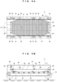
- a second tray 80 is a rectangle (oblong) in its plan view, the length along with the front and rear direction, which serves as the transport direction H, being longer than the width in the left and right direction, and has a boat-like shape with four corners diagonally cut off in plan view.
- the second tray 80 is constituted by a tray body 81 and a pair of front and rear flanges 82.
- the pair of front and rear flanges 82 are provided to protrude along the left and right direction of the tray body 81 at both ends of the tray body 81 in the front and rear direction.
- An article placement portion 83 for placing the article 90 is formed on an upper surface of the tray body 81 and between the pair of front and rear flanges 82.
- the length of the tray body 81 in the front and rear direction is much longer than the width of the tray body 81 in the left and right direction. Therefore, in a case where the four corners of the shape of the second tray 80 in plan view are not diagonally cut off, when the second tray 80 is transported in a curved path or the like in which the first tray 70 is stably transported, the four corners of the tray body 81 in plan view collide with a guide rail or the like, which is not illustrated. Therefore, as illustrated in FIG.
- the second tray 80 has inclined portions 84 obtained by diagonally cutting off the four corners of the tray body 81 in plan view.
- the inclined portions 84 By providing the inclined portions 84 in the four corners of the tray body 81 of the second tray 80, it is possible to make the transport trajectory of the second tray 80 on a belt conveyor 12 similar to the transport trajectory of the first tray 70.
- the length of the tray body 81 in the front and rear direction is formed to be longer than the length of the tray body 81 of the first tray 70 in the front and rear direction. Therefore, compared with the article 90 placed on the first tray 70, a longer article 90 is mainly placed on the second tray 80.
- the flange 82 of the second tray 80 is significantly different in shape from the flange 72 of the first tray 70. More specifically, in the second tray 80, the flange 82 is formed to be thicker in the front and rear direction than the flange 72 of the first tray 70.
- a plurality of belt conveyors 12 are arranged along the transport path.
- the belt conveyor 12 is mainly constituted by a pair of belts 13 that form a transport surface 13a in contact with bottom surfaces of both ends of the first tray 70 and the second tray 80 in a width direction, a belt holder 14 that holds the belts 13, a driving pulley 15 and a driven pulley 16 that actuate the belts 13, and a motor 17 for rotating the driving pulley 15.
- the belt conveyor 12 is not limited to the configuration constituted by the pair of belts 13, and may be constituted by, for example, a flat belt that forms the transport surface in contact with the entire bottom surfaces of the first tray 70 and the second tray 80.
- a plurality of belt conveyors 22 are arranged along the tray transport conveyor unit 11 above the tray transport conveyor unit 11.
- the belt conveyor 22 is mainly constituted by a flat belt 23 that forms a transport surface 23a for the article 90, a belt holder 24 that holds the flat belt 23, a driving pulley 25 and a driven pulley 26 that actuate the flat belt 23, and a motor 27 for rotating the driving pulley 25.
- an inclined conveyor 28 is arranged at the end of the continuous belt conveyors 22. The inclined conveyor 28 feeds the articles 90 transported by the belt conveyors 22 to the first tray 70 and the second tray 80 that are transported by the tray transport conveyor unit 11.
- the detection sensor unit 30 is provided downstream from the transport path of the article 90 formed by the article transport conveyor unit 21, and on the side of the tray transport conveyor unit 11.
- the detection sensor unit 30 is constituted by a detection start sensor 31, an article detection sensor 32, detection end sensors 33 and 34, a tray identification sensor 35 (an example of "tray identification unit"), a rear upward protrusion detection sensor 36, a front upward protrusion detection sensor 37, rear protrusion detection sensors 38 and 39 (examples of "protrusion detection unit”), and front protrusion detection sensors 40 and 41 (examples of "protrusion detection unit”).
- the detection start sensor 31 is a sensor for causing the article detection sensor 32 to start detection of the article 90.
- the detection start sensor 31 is arranged on the side of the belt conveyor 12, and at a height that allows detection of a lower front end portion 71a of the tray body 71 of the first tray 70 and a lower front end portion 81a of the tray body 81 of the second tray 80 that are transported on the belt conveyor 12.
- the detection start sensor 31 detects the lower front end portion 71a of the tray body 71 of the first tray 70, and the lower front end portion 81a of the tray body 81 of the second tray 80, detection of the article 90 by the article detection sensor 32 is started.
- the article detection sensor 32 detects the article 90 placed on the article placement portion 73 of the first tray 70 or the article placement portion 83 of the second tray 80.
- the article detection sensor 32 is arranged on the side of the belt conveyor 12, and at a height that allows detection of the article 90 placed on the article placement portion 73 of the first tray 70 or the article placement portion 83 of the second tray 80.
- the article detection sensor 32 detects the article 90, it is determined that the article 90 is placed on the article placement portion 73 of the first tray 70 or the article placement portion 83 of the second tray 80.
- the detection end sensors 33 and 34 are sensors for ending the detection of the article 90 by the article detection sensor 32.
- the detection end sensors 33 and 34 are arranged on the side of the belt conveyor 12, and at a height that allows detection of the lower front end portion 71a of the tray body 71 of the first tray 70 and the lower front end portion 81a of the tray body 81 of the second tray 80 that are transported on the belt conveyor 12.
- the first detection end sensor 33 detects the lower front end portion 71a of the tray body 71 of the first tray 70
- the detection of the article 90 on the first tray 70 by the article detection sensor 32 is completed.
- the second detection end sensor 34 detects the lower front end portion 81a of the tray body 81 of the second tray 80, the detection of the article 90 on the second tray 80 by the article detection sensor 32 is completed.
- the tray identification sensor 35 is a tray identification unit for identifying the types of trays transported on the belt conveyor 12. More specifically, the tray identification sensor 35 identifies the second tray 80.
- the tray identification sensor 35 is arranged on the side of the belt conveyor 12, and at a height that allows detection of the flange 82 of the second tray 80. As illustrated in FIG. 5B , the tray identification sensor 35 is arranged at the position that allows detection of the flange 82 of the second tray 80 at the same time that the first detection end sensor 33 detects the lower front end portion 81a of the tray body 81 of the second tray 80.
- the tray identification sensor 35 detects the flange 82 of the second tray 80, it is determined that the tray transported on the belt conveyor 12 is the second tray 80.
- the tray identification sensor 35 indirectly identifies whether the tray transported on the belt conveyor 12 is the first tray 70 or the second tray 80, by detecting only the flange 82 of the second tray 80 that is different in shape from the flange 72 of the first tray 70.
- the rear upward protrusion detection sensor 36 is a sensor that detects protrusion of the article 90 on an upper surface of the rear flange 72 of the first tray 70 and an upper surface of the rear flange 82 of the second tray 80.
- the rear upward protrusion detection sensor 36 is arranged on the side of the belt conveyor 12, and at a height that allows detection of the vicinity of the upper surface of the rear flange 72 of the first tray 70 and the vicinity of the upper surface of the rear flange 82 of the second tray 80.
- the rear upward protrusion detection sensor 36 is arranged spaced apart from the second detection end sensor 34 by a length that is substantially the same as the length between the lower front end portion 81a of the tray body 81 of the second tray 80 and the rear flange 72.
- the rear upward protrusion detection sensor 36 detects the article 90 on the upper surface of the rear flange 72 and the upper surface of the rear flange 82, it is determined that the article 90 placed on the first tray 70 or the second tray 80 is protruding from the upper surface of the rear flange 72 or the upper surface of the rear flange 82.
- the front upward protrusion detection sensor 37 is a sensor that detects the article 90 above the upper surface of the front flange 72 of the first tray 70 and the upper surface of the front flange 82 of the second tray 80.
- the front upward protrusion detection sensor 37 is arranged on the side of the belt conveyor 12, and at a height that allows detection of the vicinity of the upper surface of the front flange 72 of the first tray 70 and the vicinity of the upper surface of the front flange 82 of the second tray 80.
- the front upward protrusion detection sensor 37 is arranged spaced apart from the rear upward protrusion detection sensor 36 by a length that is substantially the same as the length between the front flange 72 and the rear flange 72 of the first tray 70.
- the front upward protrusion detection sensor 37 detects the article 90 on the upper surface of the front flange 72 and the upper surface of the front flange 82, it is determined that the article 90 placed on the first tray 70 or the second tray 80 is protruding from the upper surface of the front flange 72 or the upper surface of the front flange 82.
- the rear protrusion detection sensors 38 and 39 are sensors that detect the article 90 in the rear inclined portions 84 of the second tray 80.
- the inclined portions 84 are formed in the four corners of the tray body 81 of the second tray 80.
- the first rear protrusion detection sensor 38 and the second rear protrusion detection sensor 39 are provided on the side of the belt conveyor 12.
- the first rear protrusion detection sensor 38 and the second rear protrusion detection sensor 39 are arranged at positions that are opposite each other across the belt conveyor 12.
- the rear protrusion detection sensors 38 and 39 are arranged at a height that allows detection of the article 90 placed on the article placement portion 83 of the second tray 80, and at positions that allows detection of the article 90 along the inclination of the rear inclined portions 84 of the second tray 80.
- the rear protrusion detection sensors 38 and 39 detect the article 90 on the rear inclined portions 84 of the second tray 80, it is determined that the article 90 placed on the second tray 80 is protruding from the rear inclined portions 84 of the second tray 80. Note that, in FIG.
- the rear protrusion detection sensor 38 (the rear protrusion detection sensor 39 as well) detects the article 90 downward from the position higher than the article placement portion 83 of the second tray 80, this is not a limitation.
- the rear protrusion detection sensors 38 and 39 may detect the article 90 upward from positions lower than the article placement portion 83 of the second tray 80, or may detect the article 90 horizontally.
- the front protrusion detection sensors 40 and 41 are sensors that detect the article 90 on the front inclined portions 84 of the second tray 80.
- the first front protrusion detection sensor 40 and the second front protrusion detection sensor 41 are provided on the side of the belt conveyor 12.
- the first front protrusion detection sensor 40 and the second front protrusion detection sensor 41 are arranged at positions that are opposite each other across the belt conveyor 12.
- the front protrusion detection sensors 40 and 41 are arranged at a height that allows detection of the article 90 placed on the article placement portion 83 of the second tray 80, and at positions that allow detection of the article 90 along the inclination of the front inclined portions 84 of the second tray 80.
- the front protrusion detection sensors 40 and 41 detect the article 90 on the front inclined portions 84 of the second tray 80, it is determined that the article 90 placed on the second tray 80 is protruding from the front inclined portions 84 of the second tray 80.
- the front protrusion detection sensor 40 the front protrusion detection sensor 41 as well detects the article 90 downward from the position higher than the article placement portion 83 of the second tray 80, this is not a limitation.
- the front protrusion detection sensors 40 and 41 may detect the article 90 upward from positions lower than the article placement portion 83 of the second tray 80, or may detect the article 90 horizontally.
- the controller 50 is connected to each of the units (the tray transport conveyor unit 11, the article transport conveyor unit 21, and the detection sensor unit 30) of the transport device 10, and controls each of the units of the transport device 10. Note that the determination by each sensor of the above-described detection sensor unit 30 is performed by the controller 50.
- the detection sensor unit 30 detects whether the article 90 is placed on the article placement portion 73 of the first tray 70 and the article placement portion 83 of the second tray 80, and subsequently identifies the type of the tray transported on the belt conveyor 12, so as to detect the protrusion of the article 90 on the first tray 70 and the second tray 80.
- the detection start sensor 31 detects the lower front end portion 71a of the tray body 71 of the first tray 70 or the lower front end portion 81a of the tray body 81 of the second tray 80 transported on the belt conveyor 12 (S1)
- the detection of the article 90 by the article detection sensor 32 is started (S2).
- the article detection sensor 32 detects the article 90 until the first detection end sensor 33 detects the lower front end portion 71a of the tray body 71 of the first tray 70 or the lower front end portion 81a of the tray body 81 of the second tray 80 (S3).
- the tray identification sensor 35 identifies the type of the tray transported on the belt conveyor 12. More specifically, whether or not the tray transported on the belt conveyor 12 is the second tray 80 is determined by the detection of the tray identification sensor 35 (S5).
- the article detection sensor 32 ends the detection of the article 90 (S6).
- the rear upward protrusion detection sensor 36 and the front upward protrusion detection sensor 37 start the detection of the article 90, so as to determine the protrusion of the article 90 from the upper surfaces of both the front and rear flanges 72 of the first tray 70 (S7).
- the detection of the tray identification sensor 35 it is determined that the tray transported on the belt conveyor 12 is the second tray 80 (S5 - Yes)
- the detection of the article 90 by the article detection sensor 32 is continuously performed (S11).
- the front upward protrusion detection sensor 37 starts the detection of the article 90
- the protrusion of the article 90 from the upper surface of the front flange 82 of the second tray 80 is determined (S12).
- the protrusion of the article 90 from the upper surface of the rear flange 82 of the second tray 80, the rear inclined portions 84 of the second tray 80, and the front inclined portions 84 of the second tray 80 is determined (S18).
- the second tray 80 is transported on the belt conveyor 12 as it is.
- the detection range of the article 90 protruding from the front and rear ends of a tray is changed according to the type (the first tray 70 or the second tray 80) of the tray identified by the tray identification sensor 35. More specifically, when the tray identification sensor 35 identifies the first tray 70, the protrusion of the article 90 on the upper surfaces of the front and rear flanges 72 of the first tray 70 is detected. On the other hand, when the tray identification sensor 35 identifies the second tray 80, in addition to the protrusion of the article 90 on the upper surfaces of the front and rear flanges 82 of the second tray 80, the protrusion of the article 90 on the front and rear inclined portions 84 of the second tray 80 is detected.
- the protrusion of the article 90 from the first tray 70 and the second tray 80 can be detected. Therefore, even when the first tray 70 and the second tray 80 of different types are transported in a mixed condition, the protrusion of the article 90 from the first tray 70 and the second tray 80 can be accurately detected according to the types of the trays.
- the article 90 placed on the article placement portion 73 of the first tray 70 or the article placement portion 83 of the second tray 80 is detected by one article detection sensor 32, this is not a limitation.
- a plurality of (three in FIG. 7 ) article detection sensors 32a, 32b, and 32c may detect the article 90 placed on the article placement portion 73 of the first tray 70 or the article placement portion 83 of the second tray 80.
- the article detection sensors 32a, 32b, and 32c are arranged along the side of the belt conveyor 12 at a height that allows detection of the article 90 placed on the article placement portion 73 of the first tray 70 or the article placement portion 83 of the second tray 80.
- the detection start sensor 31 detects the lower front end portion 71a of the tray body 71 of the first tray 70 or the lower front end portion 81a of the tray body 81 of the second tray 80
- the front upward protrusion detection sensor 37 detects whether or not the article 90 exists on the upper surface of the front flange 72 of the first tray 70 or the upper surface of the front flange 82 of the second tray 80.
- the article detection sensors 32a, 32b, and 32c start the detection of the article 90 placed on the article placement portion 73 of the first tray 70 or the article placement portion 83 of the second tray 80.
- the second detection end sensor 34 detects the lower front end portion 71a of the tray body 71 of the first tray 70 or the lower front end portion 81a of the tray body 81 of the second tray 80
- the article detection sensors 32a, 32b, and 32c complete the detection of the article 90 placed on the article placement portion 73 of the first tray 70 or the article placement portion 83 of the second tray 80
- the tray identification sensor 35 identifies whether the tray transported on the belt conveyor 12 is the first tray 70 or the second tray 80.
- a first rear upward protrusion detection sensor 36a detects whether or not the article 90 exists on the upper surface of the rear flange 72 of the first tray 70.
- a second rear upward protrusion detection sensor 36b detects whether or not the article 90 exists on the upper surface of the rear flange 82 of the second tray 80.
- the rear protrusion detection sensors 38 and 39, and the front protrusion detection sensors 40 and 41 detect whether or not the article 90 exists on the rear inclined portions 84 of the second tray 80, and the front inclined portions 84 of the second tray 80.
- the detection sensor unit 30 can be made compact.
- the tray identification sensor 35 identifies the types of the trays by detecting the difference in shape between the flange 72 of the first tray 70 and the flange 82 of the second tray 80, this is not a limitation.
- the tray identification sensor 35 may identify the types of the trays by detecting the difference in shape between other portions other than the flanges (the flanges 72 and the flanges 82) of the tray body 71 of the first tray 70 and the tray body 81 of the second tray 80. More specifically, a projecting portion is formed only in the tray body 81 of the second tray 80, and the second tray 80 is identified by detecting the projecting portion by the tray identification sensor 35.
- the types of the trays may be identified by measuring the dimensions of the tray body 71 of the first tray 70 and the tray body 81 of the second tray 80 by the tray identification sensor 35.
- the types of the trays are identified by measuring the lengths of the tray body 71 of the first tray 70 and tray body 81 of the second tray 80 in a front and rear length direction by the tray identification sensor 35.
- an identifier such as a barcode, a QR Code (registered trademark), or an RFID (Radio Frequency Identification) may be attached to the first tray 70 and the second tray 80, and the types of the trays may be identified by reading the identifier by a reading unit provided around the belt conveyor 12.
- a barcode that allows identification of each tray is attached to each of the first tray 70 and the second tray 80, and the first tray 70 and the second tray 80 are identified by reading the barcode by a barcode reader provided on the side of the belt conveyor 12.
- a camera an example of “photographing unit” that photographs the first tray 70 and the second tray 80 may be provided on the side of the belt conveyor 12, above the belt conveyor 12, or the like, and the types of the trays may be identified based on an image photographed by the camera.
- the camera is provided above the belt conveyor 12, and the first tray 70 and the second tray 80 are identified by analyzing the image photographed by the camera from above the first tray 70 and the second tray 80.
- the types (the first tray 70 and the second tray 80) of the trays transported on the belt conveyor 12 are identified by identifying only the second tray 80 by the tray identification sensor 35, this is not a limitation.
- the types of the trays may be identified by identifying only the first tray 70 by the tray identification sensor 35.
- the transportation of the first tray 70 or the second tray 80 is stopped, this is not a limitation.
- the corresponding first tray 70 or second tray 80 may be guided to another transport path (for example, a dedicated conveyor unit that transports only a tray in which the protrusion of the article 90 has been detected), without being stopped on the tray transport conveyor unit 11 (the belt conveyor 12), the protrusion of the article 90 may be corrected, and thereafter, the corresponding first tray 70 or second tray 80 may be merged again into the tray transport conveyor unit 11 (the belt conveyor 12).
- a transport path for example, a dedicated conveyor unit that transports only a tray in which the protrusion of the article 90 has been detected
- the detection start sensor 31 is arranged at the height that allows detection of the lower front end portion 71a of the first tray 70 and the lower front end portion 81a of the second tray 80 that are transported on the belt conveyor 12, this is not a limitation.
- the article detection sensor 32 may be at a position that allows starting the detection of the article 90 on the first tray 70 and the second tray 80 at the timing when the detection start sensor 31 detects the first tray 70 and the second tray 80.
- the protrusion of the article 90 from the upper surface of the front flange 82 of the second tray 80, and the protrusion of the article 90 from the upper surface of the rear flange 82 of the second tray 80 are separately detected at different timings (after the first detection end sensor 33 detects the second tray 80 (S4), and after the second detection end sensor 34 detects the second tray 80 (S16)), this is not a limitation.
- the protrusion of the article 90 from the upper surface of the front flange 82 of the second tray 80, and the protrusion of the article 90 from the upper surface of the rear flange 82 of the second tray 80 may be detected at the same time.
- the detection of the article 90 by the rear upward protrusion detection sensor 36 and the front upward protrusion detection sensor 37 is performed after the tray identification sensor 35 detects the second tray 80 (S5)
Landscapes
- Engineering & Computer Science (AREA)
- Mechanical Engineering (AREA)
- Aviation & Aerospace Engineering (AREA)
- Attitude Control For Articles On Conveyors (AREA)
- Discharge Of Articles From Conveyors (AREA)
- Sorting Of Articles (AREA)
- Warehouses Or Storage Devices (AREA)
- Branching, Merging, And Special Transfer Between Conveyors (AREA)
- Control Of Conveyors (AREA)
Abstract
Description
- The present invention relates to a transport device that transports a plurality of trays of different types on which articles can be placed.
- Conventionally, as a transport device that transports trays on which articles are placed, there is a transport device as illustrated in
Japanese Patent Laid-Open No. 2018-162132 Japanese Patent Laid-Open No. 2018-162132 Japanese Patent Laid-Open No. 2018-162132 - In the conventional transport device as illustrated in
Japanese Patent Laid-Open No. 2018-162132 - On the other hand, in the conventional transport device, articles placed on trays may be transported in states where the articles are protruding from the trays. Therefore, in the conventional transport device, the protrusion of the articles from the trays is detected by sensors and the like arranged at positions that are determined according to the trays.
- However, in the conventional transport device, only trays of the same type are transported in the same transport line, and the sensors and the like that detect the protrusion of the articles from the trays are arranged at positions that are fixed for each type of tray. Therefore, when transporting articles of different sizes, it has been unfortunately necessary to form a transport line for each type of tray corresponding to the size of articles to be transported, or to unify the trays to be used into trays that can transport articles of the maximum size, leading to the problem that articles of different sizes cannot be efficiently transported. Accordingly, a transport device is desired that can transport a plurality of trays of different types in a mixed condition in the same transport line.
- Therefore, an object of the present invention is to provide a transport device that can transport a plurality of trays of different types in a mixed condition in the same transport line.
- The problem to be solved by the present invention is as described above, and solutions to the problem will be described next.
- That is, a transport device of the present invention is a transport device that transports a plurality of trays of different types on which articles can be placed, the transport device including a tray identification unit that identifies the types of the trays, and a protrusion detection unit that detects the articles placed protruding from the trays, wherein the tray identification unit identifies the types of the trays by detecting the characteristics of the trays, and the protrusion detection unit detects the articles according to the types of the trays identified by the tray identification unit.
- In the above-described configuration, the protrusion detection unit detects the articles according to the types of trays that are identified by the tray identification unit based on the characteristics of the trays.
- In the above-described transport device of the present invention, the tray identification unit preferably identifies the types of the trays by detecting the shapes of the trays.
- In the above-described configuration, the types of the trays are identified by the shapes of the trays.
- In the above-described transport device of the present invention, the tray identification unit preferably identifies the types of the trays by measuring the dimensions of the trays.
- In the above-described configuration, the types of the trays are identified by the dimensions of the trays.
- In the above-described transport device of the present invention, the tray identification unit preferably identifies the types of the trays by detecting identifiers provided to the trays.
- In the above-described configuration, the types of the trays are identified by the identifiers provided to the trays.
- The above-described transport device of the present invention preferably includes a photographing unit that photographs the trays, and the tray identification unit preferably identifies the types of the trays based on images photographed by the photographing unit.
- In the above-described configuration, the types of the trays are identified by the images photographed by the photographing unit.
- In the above-described transport device of the present invention, the protrusion detection unit preferably detects the protrusion of the articles from the front and rear ends of the trays with respect to the transport direction of the trays.
- In the above-described configuration, the protrusion of the articles from the front and rear ends of the trays is detected by the protrusion detection unit.
- In the above-described transport device of the present invention, the protrusion detection unit preferably changes the detection range of the articles protruding from the front and rear ends of the trays with respect to the transport direction of the trays, according to the types of the trays identified by the tray identification unit.
- In the above-described configuration, the detection range of the articles protruding from the front and rear ends of the trays is changed according to the types of the trays identified by the tray identification unit.
- According to the transport device of the present invention, the protrusion of the articles from the trays can be detected after identifying the types of the trays from the characteristics of the trays. Therefore, even when a plurality of trays of different types are transported in a mixed condition, the protrusion of the articles from the trays can be accurately detected according to the types of the trays.
-
- [
FIG. 1] FIG. 1 is a side view of a transport device according to the present invention. - [
FIG. 2] FIG. 2 is a block diagram illustrating each configuration of the transport device according to the present invention. - [
FIG. 3A] FIG. 3A is a plan view of a first tray, which is an example of a tray transported by the transport device according to the present invention. - [
FIG. 3B] FIG. 3B is a side view of the first tray, which is the example of the tray transported by the transport device according to the present invention. - [
FIG. 4A] FIG. 4A is a plan view of a second tray, which is another example of the tray transported by the transport device according to the present invention. - [
FIG. 4B] FIG. 4B is a side view of the second tray, which is another example of the tray transported by the transport device according to the present invention. - [
FIG. 5A] FIG. 5A is an enlarged view of a front end portion of the first tray at the time when a tray identification sensor of the transport device according to the present invention identifies the first tray. - [
FIG. 5B] FIG. 5B is an enlarged view of a front end portion of the second tray at the time when the tray identification sensor of the transport device according to the present invention identifies the second tray. - [
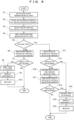
FIG. 6] FIG. 6 is a flowchart for detecting the protrusion of articles in the trays (the first tray and the second tray) transported by the transport device according to the present invention. - [
FIG. 7] FIG. 7 is a side view illustrating another example of a detection sensor unit of the transport device according to the present invention. - A
transport device 10 of the present invention will be described. Note that the present invention is not limited to thetransport device 10 illustrated below. - The
transport device 10 is, for example, a device used in a baggage transport system that performs sorting and transportation of baggage (an example of "article") from receiving the baggage from passengers in an airport until the baggage is loaded onto airplanes on which the passengers are scheduled to board. Note that thetransport device 10 is not limited to the device used in the baggage transport system in the airport, and may be a device used in a system that performs sorting and a transportation of articles. - As illustrated in
FIG. 1 andFIG. 2 , thetransport device 10 mainly includes aconveyor unit 11 for transporting a plurality of trays that transports a first tray 70 (an example of "tray") and a second tray 80 (another example of "tray"), an articletransport conveyor unit 21 that transports an article 90, adetection sensor unit 30 that detects thefirst tray 70 and thesecond tray 80, and the article 90 placed on thefirst tray 70 or thesecond tray 80, and acontroller 50 that controls theentire transport device 10. In thetransport device 10, the article 90 is transported by the articletransport conveyor unit 21 provided above the traytransport conveyor unit 11. Further, the article 90 transported by the articletransport conveyor unit 21 is fed from an end of the articletransport conveyor unit 21 to thefirst tray 70 or thesecond tray 80. Accordingly, the article 90 is placed on thefirst tray 70 or thesecond tray 80 to be transported by the traytransport conveyor unit 11. While thefirst tray 70 and thesecond tray 80 on which articles 90 are placed are transported by the traytransport conveyor unit 11, either one of thefirst tray 70 and thesecond tray 80 is detected, and the article 90 placed on thefirst tray 70 or thesecond tray 80 is detected by thedetection sensor unit 30. - The
transport device 10 transports thefirst tray 70 and thesecond tray 80 along a transport path. Note that the trays transported by thetransport device 10 are not limited to thefirst tray 70 and thesecond tray 80. Thefirst tray 70 and thesecond tray 80 are formed so that the article 90 can be placed thereon. - As illustrated in
FIG. 3A and FIG. 3B , thefirst tray 70 is formed into a rectangle (oblong) shape in its plan view, the length along with a front and rear direction, which serves as a transport direction H, being longer than the width in a left and right direction. Thefirst tray 70 is constituted by atray body 71 and a pair of front andrear flanges 72. The pair of front andrear flanges 72 are provided to protrude along the left and right direction of thetray body 71 from both ends of thetray body 71 in the front and rear direction. Anarticle placement portion 73 for placing the article 90 is formed on an upper surface of thetray body 71 and between the pair of front andrear flanges 72. - As illustrated in
FIG. 4A and FIG. 4B , asecond tray 80 is a rectangle (oblong) in its plan view, the length along with the front and rear direction, which serves as the transport direction H, being longer than the width in the left and right direction, and has a boat-like shape with four corners diagonally cut off in plan view. Thesecond tray 80 is constituted by atray body 81 and a pair of front andrear flanges 82. The pair of front andrear flanges 82 are provided to protrude along the left and right direction of thetray body 81 at both ends of thetray body 81 in the front and rear direction. Anarticle placement portion 83 for placing the article 90 is formed on an upper surface of thetray body 81 and between the pair of front andrear flanges 82. In thesecond tray 80, the length of thetray body 81 in the front and rear direction is much longer than the width of thetray body 81 in the left and right direction. Therefore, in a case where the four corners of the shape of thesecond tray 80 in plan view are not diagonally cut off, when thesecond tray 80 is transported in a curved path or the like in which thefirst tray 70 is stably transported, the four corners of thetray body 81 in plan view collide with a guide rail or the like, which is not illustrated. Therefore, as illustrated inFIG. 4A , thesecond tray 80 has inclinedportions 84 obtained by diagonally cutting off the four corners of thetray body 81 in plan view. By providing theinclined portions 84 in the four corners of thetray body 81 of thesecond tray 80, it is possible to make the transport trajectory of thesecond tray 80 on abelt conveyor 12 similar to the transport trajectory of thefirst tray 70. - As illustrated in
FIG. 3A, FIG. 3B ,FIG. 4A, and FIG. 4B , in thesecond tray 80, the length of thetray body 81 in the front and rear direction is formed to be longer than the length of thetray body 81 of thefirst tray 70 in the front and rear direction. Therefore, compared with the article 90 placed on thefirst tray 70, a longer article 90 is mainly placed on thesecond tray 80. - As illustrated in
FIG. 5A and FIG. 5B , theflange 82 of thesecond tray 80 is significantly different in shape from theflange 72 of thefirst tray 70. More specifically, in thesecond tray 80, theflange 82 is formed to be thicker in the front and rear direction than theflange 72 of thefirst tray 70. - As illustrated in
FIG. 1 andFIG. 2 , in the traytransport conveyor unit 11 that transports thefirst tray 70 and thesecond tray 80, a plurality ofbelt conveyors 12 are arranged along the transport path. Thebelt conveyor 12 is mainly constituted by a pair ofbelts 13 that form atransport surface 13a in contact with bottom surfaces of both ends of thefirst tray 70 and thesecond tray 80 in a width direction, abelt holder 14 that holds thebelts 13, a drivingpulley 15 and a drivenpulley 16 that actuate thebelts 13, and amotor 17 for rotating the drivingpulley 15. Note that thebelt conveyor 12 is not limited to the configuration constituted by the pair ofbelts 13, and may be constituted by, for example, a flat belt that forms the transport surface in contact with the entire bottom surfaces of thefirst tray 70 and thesecond tray 80. - In the article
transport conveyor unit 21 that transports the article 90, at least in the transport path near where the article 90 is fed to thefirst tray 70 and thesecond tray 80, a plurality ofbelt conveyors 22 are arranged along the traytransport conveyor unit 11 above the traytransport conveyor unit 11. Thebelt conveyor 22 is mainly constituted by aflat belt 23 that forms atransport surface 23a for the article 90, abelt holder 24 that holds theflat belt 23, a drivingpulley 25 and a drivenpulley 26 that actuate theflat belt 23, and amotor 27 for rotating the drivingpulley 25. In the articletransport conveyor unit 21, aninclined conveyor 28 is arranged at the end of thecontinuous belt conveyors 22. Theinclined conveyor 28 feeds the articles 90 transported by thebelt conveyors 22 to thefirst tray 70 and thesecond tray 80 that are transported by the traytransport conveyor unit 11. - As illustrated in
FIG. 1 andFIG. 2 , thedetection sensor unit 30 is provided downstream from the transport path of the article 90 formed by the articletransport conveyor unit 21, and on the side of the traytransport conveyor unit 11. Thedetection sensor unit 30 is constituted by adetection start sensor 31, anarticle detection sensor 32,detection end sensors protrusion detection sensor 36, a front upwardprotrusion detection sensor 37, rearprotrusion detection sensors 38 and 39 (examples of "protrusion detection unit"), and frontprotrusion detection sensors 40 and 41 (examples of "protrusion detection unit"). - The
detection start sensor 31 is a sensor for causing thearticle detection sensor 32 to start detection of the article 90. Thedetection start sensor 31 is arranged on the side of thebelt conveyor 12, and at a height that allows detection of a lowerfront end portion 71a of thetray body 71 of thefirst tray 70 and a lowerfront end portion 81a of thetray body 81 of thesecond tray 80 that are transported on thebelt conveyor 12. When thedetection start sensor 31 detects the lowerfront end portion 71a of thetray body 71 of thefirst tray 70, and the lowerfront end portion 81a of thetray body 81 of thesecond tray 80, detection of the article 90 by thearticle detection sensor 32 is started. - The
article detection sensor 32 detects the article 90 placed on thearticle placement portion 73 of thefirst tray 70 or thearticle placement portion 83 of thesecond tray 80. Thearticle detection sensor 32 is arranged on the side of thebelt conveyor 12, and at a height that allows detection of the article 90 placed on thearticle placement portion 73 of thefirst tray 70 or thearticle placement portion 83 of thesecond tray 80. When thearticle detection sensor 32 detects the article 90, it is determined that the article 90 is placed on thearticle placement portion 73 of thefirst tray 70 or thearticle placement portion 83 of thesecond tray 80. - The
detection end sensors article detection sensor 32. Thedetection end sensors belt conveyor 12, and at a height that allows detection of the lowerfront end portion 71a of thetray body 71 of thefirst tray 70 and the lowerfront end portion 81a of thetray body 81 of thesecond tray 80 that are transported on thebelt conveyor 12. When the firstdetection end sensor 33 detects the lowerfront end portion 71a of thetray body 71 of thefirst tray 70, the detection of the article 90 on thefirst tray 70 by thearticle detection sensor 32 is completed. When the seconddetection end sensor 34 detects the lowerfront end portion 81a of thetray body 81 of thesecond tray 80, the detection of the article 90 on thesecond tray 80 by thearticle detection sensor 32 is completed. - The
tray identification sensor 35 is a tray identification unit for identifying the types of trays transported on thebelt conveyor 12. More specifically, thetray identification sensor 35 identifies thesecond tray 80. Thetray identification sensor 35 is arranged on the side of thebelt conveyor 12, and at a height that allows detection of theflange 82 of thesecond tray 80. As illustrated inFIG. 5B , thetray identification sensor 35 is arranged at the position that allows detection of theflange 82 of thesecond tray 80 at the same time that the firstdetection end sensor 33 detects the lowerfront end portion 81a of thetray body 81 of thesecond tray 80. When thetray identification sensor 35 detects theflange 82 of thesecond tray 80, it is determined that the tray transported on thebelt conveyor 12 is thesecond tray 80. Here, as described above, theflange 82 of thesecond tray 80 is significantly different in shape from theflange 72 of thefirst tray 70. Therefore, thetray identification sensor 35 indirectly identifies whether the tray transported on thebelt conveyor 12 is thefirst tray 70 or thesecond tray 80, by detecting only theflange 82 of thesecond tray 80 that is different in shape from theflange 72 of thefirst tray 70. - The rear upward
protrusion detection sensor 36 is a sensor that detects protrusion of the article 90 on an upper surface of therear flange 72 of thefirst tray 70 and an upper surface of therear flange 82 of thesecond tray 80. The rear upwardprotrusion detection sensor 36 is arranged on the side of thebelt conveyor 12, and at a height that allows detection of the vicinity of the upper surface of therear flange 72 of thefirst tray 70 and the vicinity of the upper surface of therear flange 82 of thesecond tray 80. The rear upwardprotrusion detection sensor 36 is arranged spaced apart from the seconddetection end sensor 34 by a length that is substantially the same as the length between the lowerfront end portion 81a of thetray body 81 of thesecond tray 80 and therear flange 72. When the rear upwardprotrusion detection sensor 36 detects the article 90 on the upper surface of therear flange 72 and the upper surface of therear flange 82, it is determined that the article 90 placed on thefirst tray 70 or thesecond tray 80 is protruding from the upper surface of therear flange 72 or the upper surface of therear flange 82. - The front upward
protrusion detection sensor 37 is a sensor that detects the article 90 above the upper surface of thefront flange 72 of thefirst tray 70 and the upper surface of thefront flange 82 of thesecond tray 80. The front upwardprotrusion detection sensor 37 is arranged on the side of thebelt conveyor 12, and at a height that allows detection of the vicinity of the upper surface of thefront flange 72 of thefirst tray 70 and the vicinity of the upper surface of thefront flange 82 of thesecond tray 80. The front upwardprotrusion detection sensor 37 is arranged spaced apart from the rear upwardprotrusion detection sensor 36 by a length that is substantially the same as the length between thefront flange 72 and therear flange 72 of thefirst tray 70. When the front upwardprotrusion detection sensor 37 detects the article 90 on the upper surface of thefront flange 72 and the upper surface of thefront flange 82, it is determined that the article 90 placed on thefirst tray 70 or thesecond tray 80 is protruding from the upper surface of thefront flange 72 or the upper surface of thefront flange 82. - The rear
protrusion detection sensors inclined portions 84 of thesecond tray 80. In thetransport device 10, in order to make the transport trajectory of thesecond tray 80 on thebelt conveyor 12 similar to the transport trajectory of thefirst tray 70, theinclined portions 84 are formed in the four corners of thetray body 81 of thesecond tray 80. As a result, in the boat-like shapedsecond tray 80, it is necessary to detect protrusion of the article 90 from theinclined portions 84 of thesecond tray 80, which is not a problem with the rectangularfirst tray 70, by the rearprotrusion detection sensors protrusion detection sensors protrusion detection sensor 38 and the second rearprotrusion detection sensor 39 are provided on the side of thebelt conveyor 12. The first rearprotrusion detection sensor 38 and the second rearprotrusion detection sensor 39 are arranged at positions that are opposite each other across thebelt conveyor 12. The rearprotrusion detection sensors article placement portion 83 of thesecond tray 80, and at positions that allows detection of the article 90 along the inclination of the rearinclined portions 84 of thesecond tray 80. When the rearprotrusion detection sensors inclined portions 84 of thesecond tray 80, it is determined that the article 90 placed on thesecond tray 80 is protruding from the rearinclined portions 84 of thesecond tray 80. Note that, inFIG. 4B , although the rear protrusion detection sensor 38 (the rearprotrusion detection sensor 39 as well) detects the article 90 downward from the position higher than thearticle placement portion 83 of thesecond tray 80, this is not a limitation. The rearprotrusion detection sensors article placement portion 83 of thesecond tray 80, or may detect the article 90 horizontally. - The front
protrusion detection sensors inclined portions 84 of thesecond tray 80. The first frontprotrusion detection sensor 40 and the second frontprotrusion detection sensor 41 are provided on the side of thebelt conveyor 12. The first frontprotrusion detection sensor 40 and the second frontprotrusion detection sensor 41 are arranged at positions that are opposite each other across thebelt conveyor 12. The frontprotrusion detection sensors article placement portion 83 of thesecond tray 80, and at positions that allow detection of the article 90 along the inclination of the frontinclined portions 84 of thesecond tray 80. When the frontprotrusion detection sensors inclined portions 84 of thesecond tray 80, it is determined that the article 90 placed on thesecond tray 80 is protruding from the frontinclined portions 84 of thesecond tray 80. Note that, inFIG. 4B , although the front protrusion detection sensor 40 (the frontprotrusion detection sensor 41 as well) detects the article 90 downward from the position higher than thearticle placement portion 83 of thesecond tray 80, this is not a limitation. The frontprotrusion detection sensors article placement portion 83 of thesecond tray 80, or may detect the article 90 horizontally. - The
controller 50 is connected to each of the units (the traytransport conveyor unit 11, the articletransport conveyor unit 21, and the detection sensor unit 30) of thetransport device 10, and controls each of the units of thetransport device 10. Note that the determination by each sensor of the above-describeddetection sensor unit 30 is performed by thecontroller 50. - Protrusion detection of the article 90 on the
first tray 70 and thesecond tray 80 will be described. - In the
transport device 10, thedetection sensor unit 30 detects whether the article 90 is placed on thearticle placement portion 73 of thefirst tray 70 and thearticle placement portion 83 of thesecond tray 80, and subsequently identifies the type of the tray transported on thebelt conveyor 12, so as to detect the protrusion of the article 90 on thefirst tray 70 and thesecond tray 80. - As illustrated in
FIGS. 3A to 6 , when thedetection start sensor 31 detects the lowerfront end portion 71a of thetray body 71 of thefirst tray 70 or the lowerfront end portion 81a of thetray body 81 of thesecond tray 80 transported on the belt conveyor 12 (S1), the detection of the article 90 by thearticle detection sensor 32 is started (S2). Thearticle detection sensor 32 detects the article 90 until the firstdetection end sensor 33 detects the lowerfront end portion 71a of thetray body 71 of thefirst tray 70 or the lowerfront end portion 81a of thetray body 81 of the second tray 80 (S3). - When the
first tray 70 or thesecond tray 80 is transported on thebelt conveyor 12, and the firstdetection end sensor 33 detects the lowerfront end portion 71a of thetray body 71 of thefirst tray 70 or the lowerfront end portion 81a of thetray body 81 of the second tray 80 (S4), thetray identification sensor 35 identifies the type of the tray transported on thebelt conveyor 12. More specifically, whether or not the tray transported on thebelt conveyor 12 is thesecond tray 80 is determined by the detection of the tray identification sensor 35 (S5). - When it is determined that the tray transported on the
belt conveyor 12 is not the second tray 80 (S5 - No), that is, when it is identified that the tray transported on thebelt conveyor 12 is thefirst tray 70, thearticle detection sensor 32 ends the detection of the article 90 (S6). When the detection of the article 90 by thearticle detection sensor 32 ends (S6), the rear upwardprotrusion detection sensor 36 and the front upwardprotrusion detection sensor 37 start the detection of the article 90, so as to determine the protrusion of the article 90 from the upper surfaces of both the front andrear flanges 72 of the first tray 70 (S7). When it is determined that the article 90 is protruding from the upper surfaces of the flanges 72 (S7 - Yes), transportation of thefirst tray 70 is stopped (S8), and a fact that the article 90 is protruding from the upper surfaces of theflanges 72 is displayed as an abnormality on a monitor, which is not illustrated (S9). Further, when the protrusion of the article 90 from the upper surfaces of theflanges 72 are corrected by an operator, the transportation of thefirst tray 70 is restarted (S10). When it is determined that the article 90 is not protruding from the upper surfaces of the flanges 72 (S7 - No), thefirst tray 70 is transported on thebelt conveyor 12 as it is. - On the other hand, when by the detection of the
tray identification sensor 35 it is determined that the tray transported on thebelt conveyor 12 is the second tray 80 (S5 - Yes), the detection of the article 90 by thearticle detection sensor 32 is continuously performed (S11). Further, when the front upwardprotrusion detection sensor 37 starts the detection of the article 90, the protrusion of the article 90 from the upper surface of thefront flange 82 of thesecond tray 80 is determined (S12). When it is determined that the article 90 is protruding from the upper surface of the front flange 82 (S12 - Yes), the transportation of thesecond tray 80 is stopped (S13), and a fact that the article 90 is protruding from the upper surface of theflange 82 is displayed as an abnormality on the monitor, which is not illustrated (S14). Further, when the protrusion of the article 90 is corrected by the operator, the transportation of thesecond tray 80 is restarted (S15). - On the other hand, in a case where it is determined that the article 90 is not protruding from the upper surface of the front flange 82 (S12 - No), when the
second tray 80 is transported on thebelt conveyor 12, and the seconddetection end sensor 34 detects the lowerfront end portion 81a of thetray body 81 of the second tray 80 (S16), the detection of the article 90 on thesecond tray 80 by thearticle detection sensor 32 ends (S17). Additionally, at the same time, when the rear upwardprotrusion detection sensor 36, the rearprotrusion detection sensors protrusion detection sensors rear flange 82 of thesecond tray 80, the rearinclined portions 84 of thesecond tray 80, and the frontinclined portions 84 of thesecond tray 80 is determined (S18). When it is determined that the article 90 is protruding from at least one of the upper surface of therear flange 82 of thesecond tray 80, the rearinclined portions 84 of thesecond tray 80, and the frontinclined portions 84 of the second tray 80 (S18 - Yes), the transportation of thesecond tray 80 is stopped (S13), and a fact that the article 90 is protruding from at least one of the upper surface of therear flange 82, the rearinclined portions 84 of thesecond tray 80, and the frontinclined portions 84 of thesecond tray 80 is displayed as an abnormality on the monitor, which is not illustrated (S14). Further, when the protrusion of the article 90 is corrected by the operator, the transportation of thesecond tray 80 is restarted (S15). When it is determined that the article 90 is not protruding from any of the upper surface of therear flange 82 of thesecond tray 80, the rearinclined portions 84 of thesecond tray 80, and the frontinclined portions 84 of the second tray 80 (S18 - No), thesecond tray 80 is transported on thebelt conveyor 12 as it is. - In this manner, in the
transport device 10, the detection range of the article 90 protruding from the front and rear ends of a tray is changed according to the type (thefirst tray 70 or the second tray 80) of the tray identified by thetray identification sensor 35. More specifically, when thetray identification sensor 35 identifies thefirst tray 70, the protrusion of the article 90 on the upper surfaces of the front andrear flanges 72 of thefirst tray 70 is detected. On the other hand, when thetray identification sensor 35 identifies thesecond tray 80, in addition to the protrusion of the article 90 on the upper surfaces of the front andrear flanges 82 of thesecond tray 80, the protrusion of the article 90 on the front and rearinclined portions 84 of thesecond tray 80 is detected. - As described above, according to the present embodiment, after identifying the type of a tray from the shapes of the flanges of the tray (the shapes of the
flanges 82 of the second tray 80), the protrusion of the article 90 from thefirst tray 70 and thesecond tray 80 can be detected. Therefore, even when thefirst tray 70 and thesecond tray 80 of different types are transported in a mixed condition, the protrusion of the article 90 from thefirst tray 70 and thesecond tray 80 can be accurately detected according to the types of the trays. - Note that, in the present embodiment, although the article 90 placed on the
article placement portion 73 of thefirst tray 70 or thearticle placement portion 83 of thesecond tray 80 is detected by onearticle detection sensor 32, this is not a limitation. As illustrated inFIG. 7 , a plurality of (three inFIG. 7 )article detection sensors article placement portion 73 of thefirst tray 70 or thearticle placement portion 83 of thesecond tray 80. In this case, thearticle detection sensors belt conveyor 12 at a height that allows detection of the article 90 placed on thearticle placement portion 73 of thefirst tray 70 or thearticle placement portion 83 of thesecond tray 80. - In this case, when the
detection start sensor 31 detects the lowerfront end portion 71a of thetray body 71 of thefirst tray 70 or the lowerfront end portion 81a of thetray body 81 of thesecond tray 80, the front upwardprotrusion detection sensor 37 detects whether or not the article 90 exists on the upper surface of thefront flange 72 of thefirst tray 70 or the upper surface of thefront flange 82 of thesecond tray 80. At the same time, thearticle detection sensors article placement portion 73 of thefirst tray 70 or thearticle placement portion 83 of thesecond tray 80. - When the
first tray 70 or thesecond tray 80 is transported on thebelt conveyor 12, and the seconddetection end sensor 34 detects the lowerfront end portion 71a of thetray body 71 of thefirst tray 70 or the lowerfront end portion 81a of thetray body 81 of thesecond tray 80, thearticle detection sensors article placement portion 73 of thefirst tray 70 or thearticle placement portion 83 of thesecond tray 80, and at the same time, thetray identification sensor 35 identifies whether the tray transported on thebelt conveyor 12 is thefirst tray 70 or thesecond tray 80. - When the
tray identification sensor 35 determines that the tray is thefirst tray 70, a first rear upwardprotrusion detection sensor 36a detects whether or not the article 90 exists on the upper surface of therear flange 72 of thefirst tray 70. When thetray identification sensor 35 determines that the tray is thesecond tray 80, a second rear upwardprotrusion detection sensor 36b detects whether or not the article 90 exists on the upper surface of therear flange 82 of thesecond tray 80. At the same time, the rearprotrusion detection sensors protrusion detection sensors inclined portions 84 of thesecond tray 80, and the frontinclined portions 84 of thesecond tray 80. - In this manner, since the
article detection sensors article placement portion 73 of thefirst tray 70 or thearticle placement portion 83 of thesecond tray 80, the range of the sensors installed on the side of thebelt conveyor 12 can be narrowed. Therefore, thedetection sensor unit 30 can be made compact. - Additionally, in the present embodiment, although the
tray identification sensor 35 identifies the types of the trays by detecting the difference in shape between theflange 72 of thefirst tray 70 and theflange 82 of thesecond tray 80, this is not a limitation. For example, thetray identification sensor 35 may identify the types of the trays by detecting the difference in shape between other portions other than the flanges (theflanges 72 and the flanges 82) of thetray body 71 of thefirst tray 70 and thetray body 81 of thesecond tray 80. More specifically, a projecting portion is formed only in thetray body 81 of thesecond tray 80, and thesecond tray 80 is identified by detecting the projecting portion by thetray identification sensor 35. - Further, the types of the trays may be identified by measuring the dimensions of the
tray body 71 of thefirst tray 70 and thetray body 81 of thesecond tray 80 by thetray identification sensor 35. For example, the types of the trays are identified by measuring the lengths of thetray body 71 of thefirst tray 70 andtray body 81 of thesecond tray 80 in a front and rear length direction by thetray identification sensor 35. - Further, an identifier, such as a barcode, a QR Code (registered trademark), or an RFID (Radio Frequency Identification), may be attached to the
first tray 70 and thesecond tray 80, and the types of the trays may be identified by reading the identifier by a reading unit provided around thebelt conveyor 12. For example, a barcode that allows identification of each tray is attached to each of thefirst tray 70 and thesecond tray 80, and thefirst tray 70 and thesecond tray 80 are identified by reading the barcode by a barcode reader provided on the side of thebelt conveyor 12. - Further, a camera (an example of "photographing unit") that photographs the
first tray 70 and thesecond tray 80 may be provided on the side of thebelt conveyor 12, above thebelt conveyor 12, or the like, and the types of the trays may be identified based on an image photographed by the camera. For example, the camera is provided above thebelt conveyor 12, and thefirst tray 70 and thesecond tray 80 are identified by analyzing the image photographed by the camera from above thefirst tray 70 and thesecond tray 80. - Additionally, in the present embodiment, although the types (the
first tray 70 and the second tray 80) of the trays transported on thebelt conveyor 12 are identified by identifying only thesecond tray 80 by thetray identification sensor 35, this is not a limitation. The types of the trays may be identified by identifying only thefirst tray 70 by thetray identification sensor 35. - Additionally, in the present embodiment, although when the rear upward
protrusion detection sensor 36, the front upwardprotrusion detection sensor 37, the rearprotrusion detection sensors protrusion detection sensors first tray 70 or thesecond tray 80 is stopped, this is not a limitation. When the protrusion of the article 90 is detected, the correspondingfirst tray 70 orsecond tray 80 may be guided to another transport path (for example, a dedicated conveyor unit that transports only a tray in which the protrusion of the article 90 has been detected), without being stopped on the tray transport conveyor unit 11 (the belt conveyor 12), the protrusion of the article 90 may be corrected, and thereafter, the correspondingfirst tray 70 orsecond tray 80 may be merged again into the tray transport conveyor unit 11 (the belt conveyor 12). With such a configuration, since a tray in which the protrusion of the article 90 has been detected is not stopped on the tray transport conveyor unit 11 (the belt conveyor 12), it is possible to continue transportation of the subsequent trays, without stopping the transportation. - Additionally, in the present embodiment, although the
detection start sensor 31 is arranged at the height that allows detection of the lowerfront end portion 71a of thefirst tray 70 and the lowerfront end portion 81a of thesecond tray 80 that are transported on thebelt conveyor 12, this is not a limitation. Thearticle detection sensor 32 may be at a position that allows starting the detection of the article 90 on thefirst tray 70 and thesecond tray 80 at the timing when thedetection start sensor 31 detects thefirst tray 70 and thesecond tray 80. - Additionally, in the present embodiment, although the protrusion of the article 90 from the upper surface of the
front flange 82 of thesecond tray 80, and the protrusion of the article 90 from the upper surface of therear flange 82 of thesecond tray 80 are separately detected at different timings (after the firstdetection end sensor 33 detects the second tray 80 (S4), and after the seconddetection end sensor 34 detects the second tray 80 (S16)), this is not a limitation. For example, at any timing of the timing when thedetection start sensor 31 detects thesecond tray 80, the timing when the firstdetection end sensor 33 detects thesecond tray 80, or the timing when the seconddetection end sensor 34 detects thesecond tray 80, the protrusion of the article 90 from the upper surface of thefront flange 82 of thesecond tray 80, and the protrusion of the article 90 from the upper surface of therear flange 82 of thesecond tray 80 may be detected at the same time. - Additionally, in the present embodiment, although the detection of the article 90 by the rear upward
protrusion detection sensor 36 and the front upward protrusion detection sensor 37 (S7, S12) is performed after thetray identification sensor 35 detects the second tray 80 (S5), this is not a limitation. For example, it may be performed at the same time when the firstdetection end sensor 33 detects thefirst tray 70 or the second tray 80 (S4), and thetray identification sensor 35 detects the second tray 80 (S5). That is, when the firstdetection end sensor 33 detects thefirst tray 70 or thesecond tray 80, the identification of the tray, and the detection of the protrusion of the article 90 from the upper surfaces of the flanges of the tray may be started at the same time. -
- 10
- Transport Device
- 35
- Tray Identification Sensor (Tray Identification Unit)
- 38
- First Rear Protrusion Detection Sensor (Protrusion Detection Unit)
- 39
- Second Rear Protrusion Detection Sensor (Protrusion Detection Unit)
- 40
- First Front Protrusion Detection Sensor (Protrusion Detection Unit)
- 41
- Second Front Protrusion Detection Sensor (Protrusion Detection Unit)
- 70
- First Tray (Tray)
- 80
- Second Tray (Tray)
- 90
- Article
Claims (7)
- A transport device that transports a plurality of trays of different types on which articles can be placed, the transport device comprising:a tray identification unit that identifies the types of the trays; anda protrusion detection unit that detects the articles placed protruding from the trays,wherein the tray identification unit identifies the types of the trays by detecting characteristics of the trays,
andthe protrusion detection unit detects the articles according to the types of the trays identified by the tray identification unit. - The transport device according to claim 1,
wherein the tray identification unit identifies the types of the trays by detecting shapes of the trays. - The transport device according to claim 1 or claim 2,
wherein the tray identification unit identifies the types of the trays by measuring dimensions of the trays. - The transport device according to claim 1,
wherein the tray identification unit identifies the types of the trays by detecting identifiers provided to the trays. - The transport device according to claim 1, comprising:a photographing unit that photographs the trays,wherein the tray identification unit identifies the types of the trays based on images photographed by the photographing unit.
- The transport device according to claim 1,
wherein the protrusion detection unit detects protrusion of the articles from front and rear ends of the trays with respect to a transport direction of the trays. - The transport device according to claim 1,
wherein the protrusion detection unit changes a detection range of the articles protruding from front and rear ends of the trays with respect to a transport direction of the trays, according to the types of the trays identified by the tray identification unit.
Applications Claiming Priority (2)
| Application Number | Priority Date | Filing Date | Title |
|---|---|---|---|
| JP2021188238A JP7487724B2 (en) | 2021-11-19 | 2021-11-19 | Conveyor |
| PCT/JP2022/015351 WO2023089844A1 (en) | 2021-11-19 | 2022-03-29 | Transport device |
Publications (2)
| Publication Number | Publication Date |
|---|---|
| EP4434922A1 true EP4434922A1 (en) | 2024-09-25 |
| EP4434922A4 EP4434922A4 (en) | 2025-03-12 |
Family
ID=86396555
Family Applications (1)
| Application Number | Title | Priority Date | Filing Date |
|---|---|---|---|
| EP22895133.1A Pending EP4434922A4 (en) | 2021-11-19 | 2022-03-29 | TRANSPORT DEVICE |
Country Status (9)
| Country | Link |
|---|---|
| US (1) | US12577059B2 (en) |
| EP (1) | EP4434922A4 (en) |
| JP (1) | JP7487724B2 (en) |
| KR (1) | KR102939585B1 (en) |
| CN (1) | CN118339094A (en) |
| AU (1) | AU2022390691A1 (en) |
| CA (1) | CA3238324A1 (en) |
| TW (1) | TW202321135A (en) |
| WO (1) | WO2023089844A1 (en) |
Family Cites Families (10)
| Publication number | Priority date | Publication date | Assignee | Title |
|---|---|---|---|---|
| CA999320A (en) | 1972-09-28 | 1976-11-02 | Chemetron Corporation | Feeding apparatus |
| DE2821815A1 (en) | 1978-05-19 | 1979-11-22 | Keller Gmbh & Co Kg | Conveyor for brick production - has base supports height adjustable and inclinable to level of second conveyor |
| JPH089048Y2 (en) | 1989-09-29 | 1996-03-13 | 株式会社イトーキクレビオ | Container height and containment protrusion detection device |
| SU1712270A1 (en) | 1990-01-09 | 1992-02-15 | Всесоюзный Научно-Исследовательский И Проектно-Конструкторский Институт Технологии Машиностроения | Apparatus for controlling the dimensions of loads on pallets |
| JP2588799Y2 (en) | 1992-09-17 | 1999-01-13 | 株式会社資生堂 | Automatic warehouse container transporter |
| JP3538226B2 (en) | 1994-08-08 | 2004-06-14 | 川崎重工業株式会社 | Baggage handling sorting device |
| DE69813621T2 (en) | 1997-12-23 | 2004-03-25 | Crisplant A/S | CONVEYOR SYSTEM FOR PROMOTING OBJECTS OF DIFFERENT TYPES |
| US20080236108A1 (en) | 2007-03-29 | 2008-10-02 | Parmley Steven M | Package Wrapping Machine with Detection of Lip Features of Trayed Products to be Wrapped |
| JP7214939B2 (en) | 2017-03-24 | 2023-01-31 | トーヨーカネツ株式会社 | Destination designated tray transfer system |
| AT520957A1 (en) | 2018-03-09 | 2019-09-15 | Tgw Logistics Group Gmbh | Robotic system for testing a loading space of a loading aid in a storage and picking system and method of operation therefor |
-
2021
- 2021-11-19 JP JP2021188238A patent/JP7487724B2/en active Active
-
2022
- 2022-03-29 CN CN202280075679.3A patent/CN118339094A/en active Pending
- 2022-03-29 KR KR1020247017329A patent/KR102939585B1/en active Active
- 2022-03-29 US US18/710,894 patent/US12577059B2/en active Active
- 2022-03-29 WO PCT/JP2022/015351 patent/WO2023089844A1/en not_active Ceased
- 2022-03-29 AU AU2022390691A patent/AU2022390691A1/en active Pending
- 2022-03-29 EP EP22895133.1A patent/EP4434922A4/en active Pending
- 2022-03-29 CA CA3238324A patent/CA3238324A1/en active Pending
- 2022-05-23 TW TW111119022A patent/TW202321135A/en unknown
Also Published As
| Publication number | Publication date |
|---|---|
| TW202321135A (en) | 2023-06-01 |
| NZ811044A (en) | 2025-10-31 |
| KR102939585B1 (en) | 2026-03-16 |
| US12577059B2 (en) | 2026-03-17 |
| JP2023075376A (en) | 2023-05-31 |
| CN118339094A (en) | 2024-07-12 |
| JP7487724B2 (en) | 2024-05-21 |
| WO2023089844A1 (en) | 2023-05-25 |
| US20250019179A1 (en) | 2025-01-16 |
| AU2022390691A1 (en) | 2024-05-30 |
| EP4434922A4 (en) | 2025-03-12 |
| KR20240110002A (en) | 2024-07-12 |
| CA3238324A1 (en) | 2023-05-25 |
Similar Documents
| Publication | Publication Date | Title |
|---|---|---|
| KR100997071B1 (en) | Item classification system using RFID | |
| KR102010342B1 (en) | An Items Sorting System having function of Adjusting position of outlet | |
| KR20250020425A (en) | Material handling device with article scanning station | |
| CN115069566B (en) | Express sorting method, system, equipment and storage medium | |
| CN107697533B (en) | Transmission system and method | |
| EP3915906A1 (en) | Goods transport facility | |
| KR20180028915A (en) | Article transport facility | |
| US12577059B2 (en) | Transport device | |
| JP7252714B2 (en) | inspection system | |
| JP2012229105A (en) | Apparatus and method for handling recognition result, and article processing system | |
| CN120288466B (en) | A pallet material conveyability identification and handling device and method | |
| RU2847376C2 (en) | Transportation device | |
| JP7205407B2 (en) | Goods transport equipment | |
| US7629602B2 (en) | Apparatus and method for detecting overlapping flat objects with a doubles detector and electronic images of first and second flat sides of an object | |
| KR101084063B1 (en) | Assembly inspection device | |
| AU2022235846A1 (en) | System and program | |
| CN115806138A (en) | Item conveying equipment | |
| JP2002028575A (en) | Article changing system for goods judgment plant | |
| KR102764377B1 (en) | Freight sorting device using data tracking synchronization | |
| CN111906032A (en) | System and method for providing service | |
| US6311886B1 (en) | Position and direction sensing system for an inspection and handling system | |
| JP2018100177A (en) | Tray type carrying apparatus | |
| CN114684555B (en) | Article conveying equipment | |
| US8857706B2 (en) | Mail processing system with loaded tray validation | |
| JP2025108219A (en) | Baggage Handling System |
Legal Events
| Date | Code | Title | Description |
|---|---|---|---|
| STAA | Information on the status of an ep patent application or granted ep patent |
Free format text: STATUS: THE INTERNATIONAL PUBLICATION HAS BEEN MADE |
|
| PUAI | Public reference made under article 153(3) epc to a published international application that has entered the european phase |
Free format text: ORIGINAL CODE: 0009012 |
|
| STAA | Information on the status of an ep patent application or granted ep patent |
Free format text: STATUS: REQUEST FOR EXAMINATION WAS MADE |
|
| 17P | Request for examination filed |
Effective date: 20240619 |
|
| AK | Designated contracting states |
Kind code of ref document: A1 Designated state(s): AL AT BE BG CH CY CZ DE DK EE ES FI FR GB GR HR HU IE IS IT LI LT LU LV MC MK MT NL NO PL PT RO RS SE SI SK SM TR |
|
| DAV | Request for validation of the european patent (deleted) | ||
| DAX | Request for extension of the european patent (deleted) | ||
| A4 | Supplementary search report drawn up and despatched |
Effective date: 20250210 |
|
| RIC1 | Information provided on ipc code assigned before grant |
Ipc: B64F 1/36 20240101ALI20250205BHEP Ipc: B07C 5/04 20060101ALI20250205BHEP Ipc: B65G 65/00 20060101ALI20250205BHEP Ipc: B65G 43/08 20060101AFI20250205BHEP |