EP4434816A1 - Beleuchtungssystem und lampensteuerung und steuerungsverfahren - Google Patents
Beleuchtungssystem und lampensteuerung und steuerungsverfahren Download PDFInfo
- Publication number
- EP4434816A1 EP4434816A1 EP22895611.6A EP22895611A EP4434816A1 EP 4434816 A1 EP4434816 A1 EP 4434816A1 EP 22895611 A EP22895611 A EP 22895611A EP 4434816 A1 EP4434816 A1 EP 4434816A1
- Authority
- EP
- European Patent Office
- Prior art keywords
- pitch angle
- pixels
- response
- controller
- road face
- Prior art date
- Legal status (The legal status is an assumption and is not a legal conclusion. Google has not performed a legal analysis and makes no representation as to the accuracy of the status listed.)
- Withdrawn
Links
Images


Classifications
-
- B—PERFORMING OPERATIONS; TRANSPORTING
- B60—VEHICLES IN GENERAL
- B60Q—ARRANGEMENT OF SIGNALLING OR LIGHTING DEVICES, THE MOUNTING OR SUPPORTING THEREOF OR CIRCUITS THEREFOR, FOR VEHICLES IN GENERAL
- B60Q1/00—Arrangement of optical signalling or lighting devices, the mounting or supporting thereof or circuits therefor
- B60Q1/02—Arrangement of optical signalling or lighting devices, the mounting or supporting thereof or circuits therefor the devices being primarily intended to illuminate the way ahead or to illuminate other areas of way or environments
- B60Q1/04—Arrangement of optical signalling or lighting devices, the mounting or supporting thereof or circuits therefor the devices being primarily intended to illuminate the way ahead or to illuminate other areas of way or environments the devices being headlights
- B60Q1/06—Arrangement of optical signalling or lighting devices, the mounting or supporting thereof or circuits therefor the devices being primarily intended to illuminate the way ahead or to illuminate other areas of way or environments the devices being headlights adjustable, e.g. remotely-controlled from inside vehicle
- B60Q1/08—Arrangement of optical signalling or lighting devices, the mounting or supporting thereof or circuits therefor the devices being primarily intended to illuminate the way ahead or to illuminate other areas of way or environments the devices being headlights adjustable, e.g. remotely-controlled from inside vehicle automatically
- B60Q1/10—Arrangement of optical signalling or lighting devices, the mounting or supporting thereof or circuits therefor the devices being primarily intended to illuminate the way ahead or to illuminate other areas of way or environments the devices being headlights adjustable, e.g. remotely-controlled from inside vehicle automatically due to vehicle inclination, e.g. due to load distribution
- B60Q1/115—Arrangement of optical signalling or lighting devices, the mounting or supporting thereof or circuits therefor the devices being primarily intended to illuminate the way ahead or to illuminate other areas of way or environments the devices being headlights adjustable, e.g. remotely-controlled from inside vehicle automatically due to vehicle inclination, e.g. due to load distribution by electric means
-
- F—MECHANICAL ENGINEERING; LIGHTING; HEATING; WEAPONS; BLASTING
- F21—LIGHTING
- F21S—NON-PORTABLE LIGHTING DEVICES; SYSTEMS THEREOF; VEHICLE LIGHTING DEVICES SPECIALLY ADAPTED FOR VEHICLE EXTERIORS
- F21S41/00—Illuminating devices specially adapted for vehicle exteriors, e.g. headlamps
- F21S41/10—Illuminating devices specially adapted for vehicle exteriors, e.g. headlamps characterised by the light source
- F21S41/14—Illuminating devices specially adapted for vehicle exteriors, e.g. headlamps characterised by the light source characterised by the type of light source
- F21S41/141—Light emitting diodes [LED]
- F21S41/151—Light emitting diodes [LED] arranged in one or more lines
- F21S41/153—Light emitting diodes [LED] arranged in one or more lines arranged in a matrix
-
- F—MECHANICAL ENGINEERING; LIGHTING; HEATING; WEAPONS; BLASTING
- F21—LIGHTING
- F21S—NON-PORTABLE LIGHTING DEVICES; SYSTEMS THEREOF; VEHICLE LIGHTING DEVICES SPECIALLY ADAPTED FOR VEHICLE EXTERIORS
- F21S41/00—Illuminating devices specially adapted for vehicle exteriors, e.g. headlamps
- F21S41/60—Illuminating devices specially adapted for vehicle exteriors, e.g. headlamps characterised by a variable light distribution
- F21S41/65—Illuminating devices specially adapted for vehicle exteriors, e.g. headlamps characterised by a variable light distribution by acting on light sources
- F21S41/663—Illuminating devices specially adapted for vehicle exteriors, e.g. headlamps characterised by a variable light distribution by acting on light sources by switching light sources
-
- F—MECHANICAL ENGINEERING; LIGHTING; HEATING; WEAPONS; BLASTING
- F21—LIGHTING
- F21S—NON-PORTABLE LIGHTING DEVICES; SYSTEMS THEREOF; VEHICLE LIGHTING DEVICES SPECIALLY ADAPTED FOR VEHICLE EXTERIORS
- F21S41/00—Illuminating devices specially adapted for vehicle exteriors, e.g. headlamps
- F21S41/60—Illuminating devices specially adapted for vehicle exteriors, e.g. headlamps characterised by a variable light distribution
- F21S41/67—Illuminating devices specially adapted for vehicle exteriors, e.g. headlamps characterised by a variable light distribution by acting on reflectors
- F21S41/675—Illuminating devices specially adapted for vehicle exteriors, e.g. headlamps characterised by a variable light distribution by acting on reflectors by moving reflectors
-
- B—PERFORMING OPERATIONS; TRANSPORTING
- B60—VEHICLES IN GENERAL
- B60Q—ARRANGEMENT OF SIGNALLING OR LIGHTING DEVICES, THE MOUNTING OR SUPPORTING THEREOF OR CIRCUITS THEREFOR, FOR VEHICLES IN GENERAL
- B60Q1/00—Arrangement of optical signalling or lighting devices, the mounting or supporting thereof or circuits therefor
- B60Q1/02—Arrangement of optical signalling or lighting devices, the mounting or supporting thereof or circuits therefor the devices being primarily intended to illuminate the way ahead or to illuminate other areas of way or environments
- B60Q1/04—Arrangement of optical signalling or lighting devices, the mounting or supporting thereof or circuits therefor the devices being primarily intended to illuminate the way ahead or to illuminate other areas of way or environments the devices being headlights
- B60Q1/14—Arrangement of optical signalling or lighting devices, the mounting or supporting thereof or circuits therefor the devices being primarily intended to illuminate the way ahead or to illuminate other areas of way or environments the devices being headlights having dimming means
- B60Q1/1415—Dimming circuits
- B60Q1/1423—Automatic dimming circuits, i.e. switching between high beam and low beam due to change of ambient light or light level in road traffic
-
- B—PERFORMING OPERATIONS; TRANSPORTING
- B60—VEHICLES IN GENERAL
- B60Q—ARRANGEMENT OF SIGNALLING OR LIGHTING DEVICES, THE MOUNTING OR SUPPORTING THEREOF OR CIRCUITS THEREFOR, FOR VEHICLES IN GENERAL
- B60Q2300/00—Indexing codes for automatically adjustable headlamps or automatically dimmable headlamps
- B60Q2300/10—Indexing codes relating to particular vehicle conditions
- B60Q2300/13—Attitude of the vehicle body
- B60Q2300/132—Pitch
-
- B—PERFORMING OPERATIONS; TRANSPORTING
- B60—VEHICLES IN GENERAL
- B60Q—ARRANGEMENT OF SIGNALLING OR LIGHTING DEVICES, THE MOUNTING OR SUPPORTING THEREOF OR CIRCUITS THEREFOR, FOR VEHICLES IN GENERAL
- B60Q2400/00—Special features or arrangements of exterior signal lamps for vehicles
- B60Q2400/50—Projected symbol or information, e.g. onto the road or car body
-
- F—MECHANICAL ENGINEERING; LIGHTING; HEATING; WEAPONS; BLASTING
- F21—LIGHTING
- F21W—INDEXING SCHEME ASSOCIATED WITH SUBCLASSES F21K, F21L, F21S and F21V, RELATING TO USES OR APPLICATIONS OF LIGHTING DEVICES OR SYSTEMS
- F21W2102/00—Exterior vehicle lighting devices for illuminating purposes
- F21W2102/10—Arrangement or contour of the emitted light
- F21W2102/13—Arrangement or contour of the emitted light for high-beam region or low-beam region
- F21W2102/135—Arrangement or contour of the emitted light for high-beam region or low-beam region the light having cut-off lines, i.e. clear borderlines between emitted regions and dark regions
- F21W2102/14—Arrangement or contour of the emitted light for high-beam region or low-beam region the light having cut-off lines, i.e. clear borderlines between emitted regions and dark regions having vertical cut-off lines; specially adapted for adaptive high beams, i.e. wherein the beam is broader but avoids glaring other road users
-
- F—MECHANICAL ENGINEERING; LIGHTING; HEATING; WEAPONS; BLASTING
- F21—LIGHTING
- F21W—INDEXING SCHEME ASSOCIATED WITH SUBCLASSES F21K, F21L, F21S and F21V, RELATING TO USES OR APPLICATIONS OF LIGHTING DEVICES OR SYSTEMS
- F21W2103/00—Exterior vehicle lighting devices for signalling purposes
- F21W2103/60—Projection of signs from lighting devices, e.g. symbols or information being projected onto the road
Definitions
- the present disclosure relates to a vehicle lamp.
- the low beam aims to illuminate a nearby area of an own vehicle with a predetermined illuminance, whose light distribution is regulated by rules so as not to give glare to an oncoming vehicle or a preceding vehicle, and is mainly used during travel in an urban area.
- the high beam aims to illuminate a wide and far front area with a relatively high illuminance, and is mainly used during high-speed travel on a road with less traffic of oncoming vehicle or preceding vehicle.
- the high beam thus capable of providing a driver with better visibility as compared with the low beam, has however suffered from a problem of causing glare to a vehicle driver or a pedestrian ahead of the own vehicle.
- ADB adaptive driving beam
- Patent Literature 1 WO2020/262445A1
- the present inventors examined the road face drawing, to find a problem below.
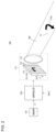
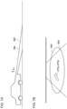
- Fig. 1 is a drawing illustrating a problem that occurs in the road face drawing.
- the posture (pitch angle) ⁇ p of a vehicle body dynamically changes during travel, while affected by a step or irregularity on the road face.
- the optical axis of a beam BM for road face drawing changes, thereby changing the angle of illumination (incident angle) on the road face.
- Change of the angle of illumination on the road face shifts a drawing position.
- the pitch angle if changes rapidly, will blur the figure drawn on the road face, thus degrading the visibility. Meanwhile, the pitch angle, if changes slowly, would undesirably make a driver or a fellow passenger feel bothered or induce carsickness.
- the posture of the vehicle body can also change statically depending on the number of passengers and the weight of baggage.
- the figure drawn on the road face would be distorted, thus degrading the visibility.
- the present disclosure has been arrived in such circumstances, and one of exemplary purposes thereof is to improve visibility of the road face drawing.
- the lamp system includes: an adaptive driving beam lamp that contains a plurality of individually controllable pixels, and is structured to illuminate a road face with beam with a light distribution pattern corresponding to states of the pixels; a sensor provided to enable detection of a pitch angle of a vehicle body; and, a controller structured to control on/off of the pixels in response to a pattern to be drawn on the road face, and to correct the states of the pixels in response to the pitch angle.
- Another mode of the present disclosure relates to a controller for an adaptive driving beam lamp that contains a plurality of individually controllable pixels, and is structured to illuminate a road face with beam with a light distribution pattern corresponding to states of the pixels.
- the controller is structured to conduct: setting on/off to the pixels in response to a pattern to be drawn on a road face; and correcting the states of the pixels in response to a pitch angle of a vehicle body.
- Still another mode of the present disclosure relates to a control method of an adaptive driving beam lamp that contains a plurality of individually controllable pixels, and is structured to illuminate a road face with beam with a light distribution pattern corresponding to states of the pixels.
- the control method includes: detecting a pitch angle of a vehicle body; and controlling on/off of the pixels in response to a pattern to be drawn on the road face, as well as correcting the states of the pixels in response to the pitch angle.
- visibility of the road face drawing may be improved.
- the lamp system includes: an adaptive driving beam lamp that contains a plurality of individually controllable pixels, and is structured to illuminate a road face with beam with a light distribution pattern corresponding to states of the pixels; a sensor provided to enable detection of a pitch angle of a vehicle body; and, a controller structured to control on/off of the pixels in response to a pattern to be drawn on the road face, and to correct the states of the pixels in response to the pitch angle.
- a pattern may be drawn at the same position (relative position with respect to the vehicle) as viewed from the vehicle, regardless of the change in the pitch angle. Thus, the visibility may be improved.
- the controller may correct the states of the pixels, in response to a dynamic change in the pitch angle of the vehicle body of the vehicle during travel. This stabilizes a position of the pattern drawing during travel, thus preventing an image from blurring, and improving the visibility.
- the controller may correct the states of the pixels, in response to the pitch angle of the vehicle body of a vehicle during standing. This successfully reduces distortion of a pattern to be drawn on the road face.
- the controller may shift a position of an on-pixel group being turned on, from among the pixels, in the vertical direction in response to the pitch angle. This successfully stabilizes the drawing position with a simple process.
- the controller may conduct the correction by changing an arrangement of an on-pixel group being turned on, from among the pixels, in response to the pitch angle. This successfully reduces distortion of a pattern to be drawn on the road face.
- the pitch angle may contain a dynamic component whose frequency is 0.5 Hz or higher.
- the senor may contain a gyro sensor.
- the dynamic pitch angle may be determined by acquiring the angular velocity in the pitch direction with use of the gyro sensor, and then by integrating the angular velocity.
- a controller is a controller for an adaptive driving beam lamp that contains a plurality of individually controllable pixels, and is structured to illuminate a road face with beam with a light distribution pattern corresponding to states of the pixels.
- the controller is structured to conduct: setting on/off to the pixels in response to a pattern to be drawn on a road face; and correcting the states of the pixels in response to a pitch angle of a vehicle body.
- a "state in which a member A is coupled to a member B" includes a case where the member A and the member B are physically and directly coupled, and a case where the member A and the member B are indirectly coupled while placing in between some other member that does not substantially affect the electrically coupled state, or does not degrade the function or effect demonstrated by the coupling thereof.
- a "state in which member C is provided between member A and member B" includes a case where the member A and the member C, or the member B and the member C are directly connected, and a case where they are indirectly connected, while placing in between some other member that does not substantially affect the electrical connection state among the members, or does not degrade the function or effect demonstrated by the members.
- Fig. 2 is a block diagram illustrating a lamp system 100 of an embodiment.
- the lamp system 100 is a road face drawing lamp that is mounted on an automobile, and illuminates a road face ahead of the vehicle with beam.
- the lamp system 100 has a high-definition lamp unit 110, a sensor 120, and a controller 200.
- the high-definition lamp unit 110 is an adaptive driving beam lamp which is structured to illuminate the road face ahead of the vehicle.
- the high-definition lamp unit 110 may alternatively cover a part/all of a low beam region.
- a high-definition lamp unit 110 has a plurality of individually controllable pixels PIX, and illuminates a road face with beam BM (referred to as road face illumination beam) with a light distribution pattern PTN corresponding to states of the pixels PIX.
- the high-definition lamp unit 110 typically includes a light emitting element array 112, and an illumination optical system 114.
- the light emitting element array 112 usable here may be an LED array.
- each pixel PIX may be controllable in two gradations of ON and OFF, or may be controllable in multiple gradations.
- the pixels, when structured to be controllable in two gradations of ON and OFF, may alternatively be expressed in multiple gradations with the aid of PWM dimming, by which the individual pixels PIX are switched at high speed, while varying the temporal ratio (duty cycle) between the on-time and the off-time.
- the illumination optical system 114 projects the output light from the light emitting element array 112, to the front of the vehicle.
- the illumination optical system 114 may be a lens optical system, a reflection optical system, or a combination thereof.
- Fig. 2 illustrates a road face 10.
- a pattern (figure) PTN is formed on the road face 10 with the road face drawing beam BM emitted from the high-definition lamp unit 110.
- the pattern PTN may be graphic information or character information, whose shape and meaning are not limited in the present disclosure.
- the light distribution pattern PTN represents an intensity distribution of the beam on the road face 10, and corresponds to an on/off pattern of the pixels PIX of a light emitting element array 112. Note that the correspondence between the position of a certain pixel PIX, with an illumination area on the road face 10 ascribed to the pixel, is determined by the illumination optical system 114, and may be occasionally given in a mirror image relation (left-right inversion), up-down inversion, or up-down and left-right inversion.
- the automobile can vary the angle of inclination in the front-rear direction (vehicle posture), in response to front-rear weight balance.
- the angle of inclination also changes in response to irregularity or step on the road face during travel.
- the angle of inclination in the front-rear direction corresponds to pivoting around a horizontal axis that extends in the left-right direction of the vehicle body, and is referred to as pitch angle (also referred to as posture angle) ⁇ p.
- the sensor 120 is provided to enable detection of the pitch angle ⁇ p of the vehicle body on which the lamp system 100 is mounted.
- the controller 200 receives, from the vehicle, drawing information INFO regarding the pattern PTN to be drawn on the road face.
- the drawing information INFO may contain data related to type and shape of the pattern.
- the drawing position may alternatively be changed in response to vehicle speed or the like.
- the drawing information INFO in this case may also contain data related to the drawing position.
- the drawing position means a relative position with respect to the vehicle.
- the controller 200 turns on a pixel group (on-pixel group) PG_ON that corresponds to the pattern PTN from among the pixels PIX of the light emitting element array 112, and turns off the remaining pixels.
- the high-definition lamp unit 110 and the controller 200 may be built in the head lamp.
- the sensor 120 may be provided on the head lamp side or on the vehicle side. When provided on the head lamp side, the sensor 120 may be incorporated in a housing (lamp body) of the head lamp, or may be externally attached to the lamp body. When provided on the vehicle side, the sensor 120 may be arranged in a vehicle cabin, or may be arranged outside the vehicle cabin, for example, in an engine room.
- the controller 200 corrects the drawing position of the pattern PTN, in response to fluctuation of the pitch angle ⁇ p ascribed to various factors during standing and travel of the vehicle.
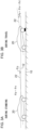
- Figs. 3(a) and (b) are drawings illustrating the pitch angles ⁇ p of the vehicle body.
- Fig. 3(a) illustrates the pitch angle ⁇ p when the vehicle stands still.
- the pitch angle ⁇ p in a stationary state of the vehicle is defined as static pitch angle ⁇ s.
- the static pitch angle ⁇ s representing the posture of the vehicle when stopped, is also referred to as a standing vehicle posture angle.
- the static pitch angle ⁇ s is determined corresponding, for example, to the number of passengers, riding position, weight of baggage in a baggage compartment, and rigidity of front and rear suspensions.
- an angle formed between a straight line 12 parallel to the road face 10 and a reference line 22 of the vehicle body 20 is defined as a pitch angle ⁇ p, and the direction in which the reference line 22 points upward (nose-up direction) is defined to be positive.
- Fig. 3(b) illustrates the pitch angle ⁇ p of the vehicle during travel.
- the pitch angle ⁇ p of the vehicle in the drive mode may be understood to be the sum of the static pitch angle ⁇ s and a dynamic component (also referred to as dynamic pitch angle or pitch angle variation) ⁇ d.
- the dynamic pitch angle ⁇ d may contain the following components.
- the pitch angle variation upon acceleration or deceleration of the vehicle body, or (ii) the change in the pitch angle due to load change of the vehicle body, which lasts for several seconds, may typically be understood to be DC fluctuation, with a very low frequency component (0.5 Hz or lower).
- the vibration of the vehicle body caused by the irregularity on the road face usually falls within the range from approximately 0.5 to 5 Hz, although depending on the rigidity of the suspension or the vehicle weight.
- the sudden vehicle body vibration typically falls in the range from 0.9 to 2 Hz.
- the controller 200 detects the pitch angle ⁇ p of the vehicle body, in response to an output (detection signal) S1 of the sensor 120.
- the pitch angle ⁇ p contains the static pitch angle ⁇ s and the dynamic pitch angle ⁇ d, as described above.
- the controller 200 shifts the position of the on-pixel group PG_ON that corresponds to the pattern PTN in the vertical direction, in response to the pitch angle ⁇ p of the vehicle body.
- the controller 200 determines a reference position y 0 of the on-pixel group PG_ON, in response to a static pitch angle ⁇ s of the vehicle obtainable while standing still. Upon detection of the dynamic pitch angle ⁇ d during travel, the controller 200 shifts the on-pixel group PG_ON in the vertical direction from the reference position y 0 .
- the sensor 120 in this embodiment contains a gyro sensor.
- the gyro sensor whose orientation of attachment is freely selectable, is preferably attached so as to align one of the detection axes with the left-right horizontal direction of the vehicle body, thereby generating a detection signal S1 that represents angular velocity ⁇ p of the rotational movement around the detection axis.
- the gyro sensor may be triaxial, or monoaxial.
- the gyro sensor enables detection of a dynamic pitch angle ⁇ d of 0.5 to 5 Hz.
- the sensor 120 may contain an acceleration sensor, besides the gyro sensor. With the acceleration sensor, it becomes possible to detect acceleration of the vehicle body while standing still, or, having no motion acceleration (that is, gravitational acceleration).
- the gravity acceleration may be used to detect the posture angle ⁇ s of the vehicle while standing still.
- the static pitch angle ⁇ s may alternatively be detected with a vehicle height sensor attached to a suspension.
- the controller 200 is an electronic control unit (ECU) in which functions related to optical axis correction are integrated, and is assigned to processing regarding the dynamic leveling.
- the controller 200 may be an ECU dedicated to leveling (also referred to as a leveling ECU), may be an ECU integrated with a controller having other functions, or may be separately embodied in a plurality of ECUs.
- the function of the controller 200 may be embodied by software processing, hardware processing, or a combination of software processing and hardware processing.
- the software processing may be specifically implemented by combining a processor (hardware) such as central processing unit (CPU), micro processing unit (MPU), or microcomputer, with software program executed by the processor (hardware).
- the controller 200 may be embodied by combination of a plurality of processors (microcontrollers).
- the hardware processing is specifically implemented by hardware such as application specific integrated circuit (ASIC), controller IC, or field programmable gate array (FPGA).
- ASIC application specific integrated circuit
- controller IC controller IC
- FPGA field programmable gate array
- the controller 200 detects the dynamic component ⁇ d in the pitch angle ⁇ p during travel of the vehicle, by integrating the angular velocity ⁇ p represented by the detection signal S1.
- the dynamic component ⁇ d may be understood as a component, out of the fluctuation of the pitch angle ⁇ p, contained in a frequency band higher than 0.5 Hz.
- a component contained in a predetermined frequency band, out of the fluctuation of the pitch angle ⁇ p is determined as the dynamic component to be corrected.
- the predetermined frequency band may be determined typically within the range from approximately 0.5 Hz to 5 Hz. Which frequency band is to be corrected may only be determined, typically depending on rigidity of the suspension, or the mass of the vehicle body.
- the controller 200 then shifts the position y of the on-pixel group, in the vertical direction with reference to the reference position y 0 , in response to the dynamic component ⁇ d of the pitch angle ⁇ p of the vehicle body during travel. More specifically, the controller 200 shifts the on-pixel group PG_ON to one of the vertical direction from the reference position y 0 , corresponding to the positive dynamic pitch angle ⁇ d; meanwhile shifts the on-pixel group PG_ON to the other one of the vertical direction from the reference position y 0 , corresponding to the negative dynamic pitch angle ⁇ d.
- the sign of the dynamic pitch angle ⁇ d and the direction of shifting of the pixels are determined according to the optical system of the high-definition lamp unit 110. This makes the pattern PTN on the road face approach the own vehicle corresponding to the positive dynamic pitch angle ⁇ d, meanwhile makes the pattern PTN on the road face shift away from the own vehicle corresponding to the negative dynamic pitch angle ⁇ d.
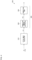
- Fig. 4 is a functional block diagram of the controller 200. Fig. 4 illustrates blocks that take part in correction of the dynamic pitch angle ⁇ p.
- the controller 200 has a pitch angle calculator 210 and a drawing position correction unit 220.
- the pitch angle calculator 210 detects the dynamic component ⁇ d in the pitch angle ⁇ p, in response to an output of the sensor 120. For example, the pitch angle calculator 210 integrates the angular velocity ⁇ p indicated by the detection signal S1. The pitch angle calculator 210 also optionally subject the integral value to arithmetic processing, to derive the dynamic pitch angle ⁇ d. This arithmetic processing may typically include filtering (band limiting), and moving average processing.
- the drawing position correction unit 220 shifts the on-pixel group PG_ON in the vertical direction, in response to the dynamic pitch angle ⁇ d.
- the drawing position correction unit 220 has a correction amount calculator 222 and a correction unit 224.
- the correction amount calculator 222 calculates the amount of shift (correction amount ⁇ y) of the on-pixel group PG_ON, in response to the dynamic pitch angle ⁇ d.
- the light emitting element array 112 has an interface through which image data that specifies ON-OFF (or luminance) of the pixels PIX is input.
- the correction unit 224 in this case may alternatively shift the position of the on-pixel group PG_ON, that corresponds to the pattern PTN contained in the image data, up or down by the correction amount ⁇ y. That is, the correction unit 224 shifts the position of the on-pixel group contained in the image data, up or down with reference to the predetermined position y 0 , so as to cancel the dynamic component ⁇ d in the pitch angle ⁇ p.
- the structure of the lamp system 100 has been described. Next, operations thereof will be explained.
- Fig. 5 is a drawing illustrating an exemplary travel scene of the vehicle.
- a vehicle 30 travels from left to right in the drawing, while getting over a step 14 on the road face 10.
- Fig. 5 illustrates postures of the vehicle 30 at a plurality of times to to t 4 .
- the individual times t 0 to t 4 stand for the following states.
- the dynamic pitch angle ⁇ d at each of the times to, t 2 , and t 4 equals 0.
- the dynamic pitch angle ⁇ d at time t 1 has a positive value ⁇ d 1
- the dynamic pitch angle ⁇ d at time t 3 has a negative value ⁇ d 3 .
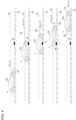
- Fig. 6 is a drawing illustrating a waveform of dynamic pitch angle ⁇ d and a waveform of correction amount ⁇ y, corresponded to the travel scene illustrated in Fig. 5 .
- the dynamic pitch angle ⁇ d swings in the positive direction, then swings in the negative direction, and finally returns to 0.
- the correction amount ⁇ y of the on-pixel group PG_ON is generated so as to cancel the fluctuation of the dynamic pitch angle ⁇ d.
- Figs. 7(a) and (b) are drawings illustrating operations of the lamp system 100 according to an embodiment.
- Fig. 7(a) illustrates a change in the vehicle posture, that is, the pitch angle ⁇ p.
- a position of the on-pixel group PG_ON of the high-definition lamp unit 110 is corrected. This keeps the angle of illumination (incident angle) of the road face drawing beam BM on the road face 10 constant, and keeps the drawing position (relative position with the vehicle) of the pattern PTN constant, regardless of the pitch angle ⁇ p. Since, as illustrated in Fig. 7(b) , the pattern PTN to be drawn on the road face 10 is drawn at the same position regardless of the change in the pitch angle ⁇ p, so that the blurring is suppressed, and the visibility may be improved.
- the pattern PTN on the road face would occasionally be distorted only by simply shifting the on-pixel group PG_ON up or down, depending on the design of the illumination optical system 114. Distorted pattern PTN will be a cause of degraded visibility.
- the controller 200 in this case may also correct the shape of the on-pixel group PG_ON that corresponds to the same pattern PTN, in response to the pitch angle ⁇ p.
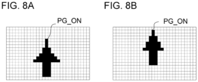
- Figs. 8(a) and (b) are drawings illustrating correction of the on-pixel group PG_ON.
- filled pixels represent the on-pixel group PG_ON.
- Figs. 8 (a) and (b) illustrate the on-pixel groups PG_ON corresponded to different pitch angles ⁇ p, which differ in the position y, and the shape of arrangement of the on-pixel groups PG_ON.
- the shapes of the on-pixel groups PG_ON are corrected so as to equalize the patterns to be drawn on the road face.
- the controller 200 may determine the reference position y 0 of the on-pixel group PG_ON with reference to the static pitch angle ⁇ s, and may concurrently correct the shape of the on-pixel group PG_ON. Then, the controller 200 may shift the corrected on-pixel group PG_ON in the vertical direction, in response to the dynamic pitch angle ⁇ d.
- the controller 200 may determine the reference position y 0 of the on-pixel group PG_ON, with reference to the static pitch angle ⁇ s.
- the controller 200 may shift the position of the on-pixel group PG_ON from the reference position y 0 in response to the dynamic pitch angle ⁇ d, and may concurrently correct the shape of the on-pixel group PG_ON.
- the pattern PTN on the road face may be suppressed from deforming, thereby preventing the visibility from degrading.
- the embodiment has detected the dynamic component of the pitch angle with use of the gyro sensor.
- the present disclosure is, however, not limited thereto.
- the dynamic component of the pitch angle may be detected with use of a combination of a front vehicle height sensor arranged on the front suspension of the vehicle body, and a rear vehicle height sensor arranged on the rear suspension of the vehicle body.
- the embodiment has constituted the high-definition lamp unit 110 with the light emitting element array 112.
- the high-definition lamp unit 110 may contain a light source that generates light with a substantially flat intensity distribution, and a spatial light modulator that spatially patterns the emitted light of the light source.
- the spatial light modulator is exemplified by digital micromirror device (DMD), and liquid crystal device.
- the method by which the controller 200 shifts the position of the on-pixel group PG_ON in the vertical direction is not limited to a method of correcting the image data to be supplied to the light emitting element array 112.
- the light emitting element array 112 may have a pixel shifting function. In this case, the light emitting element array 112 may only be given the image data as the reference, and the pixel shift amount ⁇ y.
- the controller 200 may conduct the correction, only with reference to the change in the static pitch angle ⁇ s.
- the present disclosure relates to a vehicle lamp.
Landscapes
- Engineering & Computer Science (AREA)
- General Engineering & Computer Science (AREA)
- Physics & Mathematics (AREA)
- Mechanical Engineering (AREA)
- Mathematical Physics (AREA)
- Microelectronics & Electronic Packaging (AREA)
- Optics & Photonics (AREA)
- Lighting Device Outwards From Vehicle And Optical Signal (AREA)
Applications Claiming Priority (2)
| Application Number | Priority Date | Filing Date | Title |
|---|---|---|---|
| JP2021188627 | 2021-11-19 | ||
| PCT/JP2022/042449 WO2023090330A1 (ja) | 2021-11-19 | 2022-11-15 | 灯具システムおよびランプのコントローラおよび制御方法 |
Publications (2)
| Publication Number | Publication Date |
|---|---|
| EP4434816A1 true EP4434816A1 (de) | 2024-09-25 |
| EP4434816A4 EP4434816A4 (de) | 2025-03-12 |
Family
ID=86397092
Family Applications (1)
| Application Number | Title | Priority Date | Filing Date |
|---|---|---|---|
| EP22895611.6A Withdrawn EP4434816A4 (de) | 2021-11-19 | 2022-11-15 | Beleuchtungssystem und lampensteuerung und steuerungsverfahren |
Country Status (5)
| Country | Link |
|---|---|
| US (1) | US20240302018A1 (de) |
| EP (1) | EP4434816A4 (de) |
| JP (1) | JPWO2023090330A1 (de) |
| CN (1) | CN118265633A (de) |
| WO (1) | WO2023090330A1 (de) |
Families Citing this family (1)
| Publication number | Priority date | Publication date | Assignee | Title |
|---|---|---|---|---|
| CN120191283B (zh) * | 2025-05-27 | 2025-07-22 | 常州星宇车灯股份有限公司 | 一种基于悬架高度调节的双灯投影自适应修正方法和系统 |
Family Cites Families (7)
| Publication number | Priority date | Publication date | Assignee | Title |
|---|---|---|---|---|
| US20140267415A1 (en) * | 2013-03-12 | 2014-09-18 | Xueming Tang | Road marking illuminattion system and method |
| DE102015012416A1 (de) * | 2015-09-25 | 2017-03-30 | Audi Ag | Projizieren eines vorgebbaren Lichtmusters |
| FR3055431B1 (fr) * | 2016-09-01 | 2019-08-02 | Valeo Vision | Dispositif de projection d'une image pixelisee |
| DE102016122066A1 (de) * | 2016-11-16 | 2018-05-17 | Automotive Lighting Reutlingen Gmbh | Verfahren zur Einstellung der Winkellage der optischen Achse eines Scheinwerfers eines Kraftfahrzeugs und Beleuchtungseinrichtung des Kraftfahrzeugs |
| KR101916724B1 (ko) * | 2016-12-27 | 2018-11-08 | 엘지전자 주식회사 | 차량용 램프 및 그것의 제어방법 |
| WO2020262445A1 (ja) | 2019-06-28 | 2020-12-30 | 株式会社小糸製作所 | 灯具システム |
| JP7211304B2 (ja) * | 2019-08-26 | 2023-01-24 | 株式会社デンソー | 表示装置 |
-
2022
- 2022-11-15 EP EP22895611.6A patent/EP4434816A4/de not_active Withdrawn
- 2022-11-15 JP JP2023562353A patent/JPWO2023090330A1/ja active Pending
- 2022-11-15 WO PCT/JP2022/042449 patent/WO2023090330A1/ja not_active Ceased
- 2022-11-15 CN CN202280076583.9A patent/CN118265633A/zh active Pending
-
2024
- 2024-05-16 US US18/666,130 patent/US20240302018A1/en active Pending
Also Published As
| Publication number | Publication date |
|---|---|
| US20240302018A1 (en) | 2024-09-12 |
| EP4434816A4 (de) | 2025-03-12 |
| WO2023090330A1 (ja) | 2023-05-25 |
| CN118265633A (zh) | 2024-06-28 |
| JPWO2023090330A1 (de) | 2023-05-25 |
Similar Documents
| Publication | Publication Date | Title |
|---|---|---|
| US11704910B2 (en) | Vehicle detecting device and vehicle lamp system | |
| US12503038B2 (en) | Lamp system | |
| EP2399774B1 (de) | Steuerungsvorrichtung für Fahrzeuglampe, Fahrzeugbeleuchtungssystem und Fahrzeuglampe | |
| EP2784581A1 (de) | Projektor und Head-Up-Anzeigevorrichtung und Lichtdimmer-Steuerungsverfahren | |
| JP2008044603A (ja) | 車両用防眩装置 | |
| CN110709281A (zh) | 车辆用灯具及其控制装置、控制方法 | |
| CN210637972U (zh) | 车辆用前照灯 | |
| US20240302018A1 (en) | Lamp system | |
| CN112349256A (zh) | 显示控制装置、显示控制方法及存储介质 | |
| CN114025983B (zh) | 显示控制装置及方法、图像显示系统、移动体、记录介质 | |
| JP2022161901A (ja) | 表示制御装置及び表示制御プログラム | |
| US12358417B2 (en) | Lamp system | |
| US20250376105A1 (en) | Vehicle lamp system | |
| WO2023090331A1 (ja) | 灯具システムおよびランプの制御方法 | |
| US20250326350A1 (en) | Vehicle lamp apparatus | |
| EP4681988A1 (de) | Beleuchtungssystem, lampensteuerung und steuerungsverfahren | |
| EP4631787A1 (de) | Fahrzeugleuchte und steuerung hierfür | |
| JP2025179887A (ja) | 制御装置、車両用灯具システム、およびソフトウェアプログラム | |
| US12508981B2 (en) | Lamp system | |
| KR20260015196A (ko) | 차량용 디스플레이 장치 | |
| WO2025159052A1 (ja) | 配光可変ランプの制御装置、車両用灯具、ソフトウェアプログラム | |
| JP2007230483A (ja) | 車両用灯具の照射方向制御装置 | |
| WO2025079504A1 (ja) | 車両用灯具、配光可変ランプの制御装置、ソフトウェアプログラム | |
| CN118922335A (zh) | 配光控制装置、车辆用灯具系统以及配光控制方法 |
Legal Events
| Date | Code | Title | Description |
|---|---|---|---|
| STAA | Information on the status of an ep patent application or granted ep patent |
Free format text: STATUS: THE INTERNATIONAL PUBLICATION HAS BEEN MADE |
|
| PUAI | Public reference made under article 153(3) epc to a published international application that has entered the european phase |
Free format text: ORIGINAL CODE: 0009012 |
|
| STAA | Information on the status of an ep patent application or granted ep patent |
Free format text: STATUS: REQUEST FOR EXAMINATION WAS MADE |
|
| 17P | Request for examination filed |
Effective date: 20240516 |
|
| AK | Designated contracting states |
Kind code of ref document: A1 Designated state(s): AL AT BE BG CH CY CZ DE DK EE ES FI FR GB GR HR HU IE IS IT LI LT LU LV MC ME MK MT NL NO PL PT RO RS SE SI SK SM TR |
|
| REG | Reference to a national code |
Ref country code: DE Ref legal event code: R079 Free format text: PREVIOUS MAIN CLASS: B60Q0001500000 Ipc: B60Q0001115000 |
|
| DAV | Request for validation of the european patent (deleted) | ||
| DAX | Request for extension of the european patent (deleted) | ||
| A4 | Supplementary search report drawn up and despatched |
Effective date: 20250210 |
|
| RIC1 | Information provided on ipc code assigned before grant |
Ipc: F21S 41/153 20180101ALI20250204BHEP Ipc: B60Q 1/115 20060101AFI20250204BHEP |
|
| STAA | Information on the status of an ep patent application or granted ep patent |
Free format text: STATUS: THE APPLICATION IS DEEMED TO BE WITHDRAWN |
|
| 18D | Application deemed to be withdrawn |
Effective date: 20250828 |