EP4432680A2 - Thermal-control system for a security camera and associated security cameras - Google Patents
Thermal-control system for a security camera and associated security cameras Download PDFInfo
- Publication number
- EP4432680A2 EP4432680A2 EP24192945.4A EP24192945A EP4432680A2 EP 4432680 A2 EP4432680 A2 EP 4432680A2 EP 24192945 A EP24192945 A EP 24192945A EP 4432680 A2 EP4432680 A2 EP 4432680A2
- Authority
- EP
- European Patent Office
- Prior art keywords
- thermal
- security camera
- control system
- heat sink
- heat
- Prior art date
- Legal status (The legal status is an assumption and is not a legal conclusion. Google has not performed a legal analysis and makes no representation as to the accuracy of the status listed.)
- Pending
Links
Images



Classifications
-
- G—PHYSICS
- G03—PHOTOGRAPHY; CINEMATOGRAPHY; ANALOGOUS TECHNIQUES USING WAVES OTHER THAN OPTICAL WAVES; ELECTROGRAPHY; HOLOGRAPHY
- G03B—APPARATUS OR ARRANGEMENTS FOR TAKING PHOTOGRAPHS OR FOR PROJECTING OR VIEWING THEM; APPARATUS OR ARRANGEMENTS EMPLOYING ANALOGOUS TECHNIQUES USING WAVES OTHER THAN OPTICAL WAVES; ACCESSORIES THEREFOR
- G03B17/00—Details of cameras or camera bodies; Accessories therefor
- G03B17/55—Details of cameras or camera bodies; Accessories therefor with provision for heating or cooling, e.g. in aircraft
-
- G—PHYSICS
- G08—SIGNALLING
- G08B—SIGNALLING SYSTEMS, e.g. PERSONAL CALLING SYSTEMS; ORDER TELEGRAPHS; ALARM SYSTEMS
- G08B13/00—Burglar, theft or intruder alarms
- G08B13/18—Actuation by interference with heat, light, or radiation of shorter wavelength; Actuation by intruding sources of heat, light, or radiation of shorter wavelength
- G08B13/189—Actuation by interference with heat, light, or radiation of shorter wavelength; Actuation by intruding sources of heat, light, or radiation of shorter wavelength using passive radiation detection systems
- G08B13/194—Actuation by interference with heat, light, or radiation of shorter wavelength; Actuation by intruding sources of heat, light, or radiation of shorter wavelength using passive radiation detection systems using image scanning and comparing systems
- G08B13/196—Actuation by interference with heat, light, or radiation of shorter wavelength; Actuation by intruding sources of heat, light, or radiation of shorter wavelength using passive radiation detection systems using image scanning and comparing systems using television cameras
- G08B13/19617—Surveillance camera constructional details
- G08B13/19619—Details of casing
-
- G—PHYSICS
- G08—SIGNALLING
- G08B—SIGNALLING SYSTEMS, e.g. PERSONAL CALLING SYSTEMS; ORDER TELEGRAPHS; ALARM SYSTEMS
- G08B13/00—Burglar, theft or intruder alarms
- G08B13/18—Actuation by interference with heat, light, or radiation of shorter wavelength; Actuation by intruding sources of heat, light, or radiation of shorter wavelength
- G08B13/189—Actuation by interference with heat, light, or radiation of shorter wavelength; Actuation by intruding sources of heat, light, or radiation of shorter wavelength using passive radiation detection systems
- G08B13/194—Actuation by interference with heat, light, or radiation of shorter wavelength; Actuation by intruding sources of heat, light, or radiation of shorter wavelength using passive radiation detection systems using image scanning and comparing systems
- G08B13/196—Actuation by interference with heat, light, or radiation of shorter wavelength; Actuation by intruding sources of heat, light, or radiation of shorter wavelength using passive radiation detection systems using image scanning and comparing systems using television cameras
- G08B13/19617—Surveillance camera constructional details
- G08B13/1963—Arrangements allowing camera rotation to change view, e.g. pivoting camera, pan-tilt and zoom [PTZ]
-
- G—PHYSICS
- G08—SIGNALLING
- G08B—SIGNALLING SYSTEMS, e.g. PERSONAL CALLING SYSTEMS; ORDER TELEGRAPHS; ALARM SYSTEMS
- G08B13/00—Burglar, theft or intruder alarms
- G08B13/18—Actuation by interference with heat, light, or radiation of shorter wavelength; Actuation by intruding sources of heat, light, or radiation of shorter wavelength
- G08B13/189—Actuation by interference with heat, light, or radiation of shorter wavelength; Actuation by intruding sources of heat, light, or radiation of shorter wavelength using passive radiation detection systems
- G08B13/194—Actuation by interference with heat, light, or radiation of shorter wavelength; Actuation by intruding sources of heat, light, or radiation of shorter wavelength using passive radiation detection systems using image scanning and comparing systems
- G08B13/196—Actuation by interference with heat, light, or radiation of shorter wavelength; Actuation by intruding sources of heat, light, or radiation of shorter wavelength using passive radiation detection systems using image scanning and comparing systems using television cameras
- G08B13/19617—Surveillance camera constructional details
- G08B13/19632—Camera support structures, e.g. attachment means, poles
-
- H—ELECTRICITY
- H04—ELECTRIC COMMUNICATION TECHNIQUE
- H04N—PICTORIAL COMMUNICATION, e.g. TELEVISION
- H04N23/00—Cameras or camera modules comprising electronic image sensors; Control thereof
- H04N23/50—Constructional details
- H04N23/52—Elements optimising image sensor operation, e.g. for electromagnetic interference [EMI] protection or temperature control by heat transfer or cooling elements
-
- H—ELECTRICITY
- H04—ELECTRIC COMMUNICATION TECHNIQUE
- H04N—PICTORIAL COMMUNICATION, e.g. TELEVISION
- H04N23/00—Cameras or camera modules comprising electronic image sensors; Control thereof
- H04N23/50—Constructional details
- H04N23/54—Mounting of pick-up tubes, electronic image sensors, deviation or focusing coils
-
- H—ELECTRICITY
- H05—ELECTRIC TECHNIQUES NOT OTHERWISE PROVIDED FOR
- H05K—PRINTED CIRCUITS; CASINGS OR CONSTRUCTIONAL DETAILS OF ELECTRIC APPARATUS; MANUFACTURE OF ASSEMBLAGES OF ELECTRICAL COMPONENTS
- H05K7/00—Constructional details common to different types of electric apparatus
- H05K7/20—Modifications to facilitate cooling, ventilating, or heating
- H05K7/2039—Modifications to facilitate cooling, ventilating, or heating characterised by the heat transfer by conduction from the heat generating element to a dissipating body
- H05K7/20436—Inner thermal coupling elements in heat dissipating housings, e.g. protrusions or depressions integrally formed in the housing
- H05K7/20445—Inner thermal coupling elements in heat dissipating housings, e.g. protrusions or depressions integrally formed in the housing the coupling element being an additional piece, e.g. thermal standoff
- H05K7/20472—Sheet interfaces
-
- H—ELECTRICITY
- H05—ELECTRIC TECHNIQUES NOT OTHERWISE PROVIDED FOR
- H05K—PRINTED CIRCUITS; CASINGS OR CONSTRUCTIONAL DETAILS OF ELECTRIC APPARATUS; MANUFACTURE OF ASSEMBLAGES OF ELECTRICAL COMPONENTS
- H05K7/00—Constructional details common to different types of electric apparatus
- H05K7/20—Modifications to facilitate cooling, ventilating, or heating
- H05K7/2039—Modifications to facilitate cooling, ventilating, or heating characterised by the heat transfer by conduction from the heat generating element to a dissipating body
- H05K7/20509—Multiple-component heat spreaders; Multi-component heat-conducting support plates; Multi-component non-closed heat-conducting structures
-
- G—PHYSICS
- G08—SIGNALLING
- G08B—SIGNALLING SYSTEMS, e.g. PERSONAL CALLING SYSTEMS; ORDER TELEGRAPHS; ALARM SYSTEMS
- G08B13/00—Burglar, theft or intruder alarms
- G08B13/18—Actuation by interference with heat, light, or radiation of shorter wavelength; Actuation by intruding sources of heat, light, or radiation of shorter wavelength
- G08B13/189—Actuation by interference with heat, light, or radiation of shorter wavelength; Actuation by intruding sources of heat, light, or radiation of shorter wavelength using passive radiation detection systems
- G08B13/194—Actuation by interference with heat, light, or radiation of shorter wavelength; Actuation by intruding sources of heat, light, or radiation of shorter wavelength using passive radiation detection systems using image scanning and comparing systems
- G08B13/196—Actuation by interference with heat, light, or radiation of shorter wavelength; Actuation by intruding sources of heat, light, or radiation of shorter wavelength using passive radiation detection systems using image scanning and comparing systems using television cameras
- G08B13/19617—Surveillance camera constructional details
-
- H—ELECTRICITY
- H04—ELECTRIC COMMUNICATION TECHNIQUE
- H04N—PICTORIAL COMMUNICATION, e.g. TELEVISION
- H04N23/00—Cameras or camera modules comprising electronic image sensors; Control thereof
- H04N23/50—Constructional details
- H04N23/51—Housings
-
- H—ELECTRICITY
- H05—ELECTRIC TECHNIQUES NOT OTHERWISE PROVIDED FOR
- H05K—PRINTED CIRCUITS; CASINGS OR CONSTRUCTIONAL DETAILS OF ELECTRIC APPARATUS; MANUFACTURE OF ASSEMBLAGES OF ELECTRICAL COMPONENTS
- H05K7/00—Constructional details common to different types of electric apparatus
- H05K7/20—Modifications to facilitate cooling, ventilating, or heating
- H05K7/2039—Modifications to facilitate cooling, ventilating, or heating characterised by the heat transfer by conduction from the heat generating element to a dissipating body
- H05K7/20436—Inner thermal coupling elements in heat dissipating housings, e.g. protrusions or depressions integrally formed in the housing
- H05K7/20445—Inner thermal coupling elements in heat dissipating housings, e.g. protrusions or depressions integrally formed in the housing the coupling element being an additional piece, e.g. thermal standoff
- H05K7/20454—Inner thermal coupling elements in heat dissipating housings, e.g. protrusions or depressions integrally formed in the housing the coupling element being an additional piece, e.g. thermal standoff with a conformable or flexible structure compensating for irregularities, e.g. cushion bags, thermal paste
Definitions
- a security camera may be battery-powered and include multiple integrated circuit (IC) devices, such as a passive infrared (PIR) sensor IC device that detects motion and an image sensor IC device that captures images.
- IC integrated circuit
- PIR passive infrared
- SoC system-on-chip
- the security camera may, in some instances, include a thermal-control system fabricated using a stamped sheet metal structure that can dissipate heat from the SoC IC device during a low thermal-loading condition, such as when the security camera is operating in an event-based recording (EBR) mode that is triggered by a motion detected through the PIR sensor IC device.
- EBR event-based recording
- the SoC IC device may dissipate heat at a rate of up to 2.5 Watts (W) for several seconds.
- W Power
- the thermal-control system may be capable of dissipating the heat from the low thermal-loading condition to maintain a single prescribed temperature threshold across the multiple IC devices, effectively treating the security camera as a single thermal zone.
- the SoC IC device may dissipate heat at a rate of up to 2.5 W continually.
- the high thermal-loading condition on the security camera may increase even further ( e.g ., increase further beyond 2.5 W).
- the thermal-control system may be inadequate to maintain the single prescribed temperature threshold across the multiple IC devices.
- the inability of the thermal-control system to dissipate heat from the security camera may result in (i) damage to one or more IC devices of the security camera and/or (ii) a housing of the security camera exceeding a prescribed ergonomic touch-temperature threshold.
- the thermal-control system includes a combination of heatsinks and thermal interface materials (TIMs) with high thermal conductivities.
- TIMs thermal interface materials
- the thermal-control system may transfer and spread energy from a high thermal-loading condition effectuated upon the security camera to concurrently maintain temperatures of multiple thermal zones on or within the security camera at or below prescribed temperature thresholds.
- a thermal-control system for a security camera includes a first thermal-control subsystem that is configured to transfer a first quantity of heat to a housing.
- the first thermal-control subsystem includes a first TIM that is located between an SoC IC device and a first heat sink, where the SoC IC device is mounted to a first surface of a first printed circuit board (PCB).
- the first thermal-control subsystem also includes a second TIM that is located between a memory IC device, such as a double-data rate (DDR) memory IC device, and the first heat sink.
- the memory IC device like the SoC IC device, is mounted to the first surface of the PCB.
- the first thermal-control subsystem also includes a third TIM that is located between a second surface of the first PCB and a second heat sink, where the second surface of the first PCB is opposite the first surface of the first PCB.
- the thermal-control system for the security camera also includes a second thermal-control subsystem that is configured to transfer a second quantity of heat to the housing.
- the second thermal-control subsystem includes a fourth TIM that is located between a second surface of a second PCB and a heat spreader. The second surface of the second PCB is opposite a first surface of the second PCB to which a passive infrared sensor IC device and an image sensor IC device are mounted.
- a security camera in some other aspects, includes an SoC IC device mounted to a surface of a PCB, a memory IC device mounted to the surface of the PCB, and a battery.
- the security camera also includes a thermal-control system configured to concurrently maintain temperatures through the security camera during a high thermal-loading condition.
- the thermal-control system is configured to concurrently maintain (i) a first temperature of a first thermal zone that includes the SoC IC device at or below a first prescribed temperature threshold, (ii) a second temperature of a second thermal zone that includes the memory IC device at or below a second prescribed temperature threshold, and (iii) a third temperature of a third thermal zone that includes the battery at or below a third prescribed temperature threshold.
- the thermal-control system includes a combination of heatsinks and thermal interface materials (TIMs) with high thermal conductivities.
- the thermal-control system may transfer and spread energy from a high thermal-loading condition effectuated upon the security camera to concurrently maintain temperatures of multiple thermal zones on or within the security camera at or below prescribed temperature thresholds.
- Heat transfer in general, is energy that is in transit due to a temperature difference. If one or more temperature differences exist across components of a system, such as the security camera, heat (e.g ., energy in Joules) will transfer from higher temperature zones to lower temperature zones to minimize the temperature differences. There are several mechanisms for heat transfer across the components of a system to minimize temperature differences, including convection, radiation, and conduction.
- q conv represents a rate of heat transfer from a surface through convection (e.g ., in Joules per second or Watts (W))
- h represents a convection heat transfer coefficient (e.g., in W per meter squared (W/m 2 ))
- T s represents a temperature of a surface (e.g., in Kelvin (K) or degrees Celsius (°C))
- T ⁇ represents a temperature of a fluid (e.g., in K or °C) to which the surface is exposed.
- A represents the area of a surface ( e.g ., in m 2 ).
- q rad represents a rate of heat transfer through radiation (e.g., in W)
- ⁇ represents emissivity (dimensionless)
- T s represents a temperature of a surface (e.g., in K or °C)
- T surr represents a temperature of surroundings of the surface ( e.g., in K or °C).
- A represents an area of the surface (e.g., in m 2 ).
- q cond represents a rate of heat transfer in a solid material through conduction (e.g ., in W)
- k represents a thermal conductivity of the solid material (e.g., in W/(m•K))
- dT / dx represents a temperature gradient through the solid material ( e.g ., in K/m or °C/m).
- A represents a cross-sectional area of the solid material ( e.g ., in m 2 ).
- heat transfer between components may occur using one or more of the heat transfer mechanisms described above.
- heat transfer can be varied by increasing or decreasing surface areas for convection and/or radiation within the security camera (e.g ., increasing or decreasing surface areas of heat sinks and/or heat spreading mechanisms).
- heat transfer can be varied by choosing one or more TIMs having specific thermal conductivities.
- a thermal-control system of the security camera can concurrently maintain temperatures of different thermal zones at or below different prescribed temperature thresholds during a high thermal-loading condition.
- FIG. 1 illustrates an example operating environment 100 in which a thermal-control system for a security camera can be implemented.
- a solar source e.g., the sun
- a solar heat load 104 e.g., q s
- at least one electronic device e.g., at least one IC device
- an internal heat load 106 e.g., q i
- the operating environment 100 may include a 1000 W/m 2 solar heat load 104 and a 2.5 W internal heat load 106.
- the security camera 102 includes a thermal-control system 108.
- the thermal-control system 108 may include one or more thermal-control subsystems.
- the thermal-control system 108 may include a main PCB thermal-control subsystem 110 having heat transfer mechanisms that contribute to transferring heat from a main PCB populated with an SoC IC device and one or more memory IC devices to a housing of the security camera 102.
- the thermal-control system 108 may also include a sensor PCB thermal-control subsystem 112 having other heat transfer mechanisms that contribute to transferring heat from a sensor PCB populated with a PIR sensor IC device and an image sensor IC device to the housing of the security camera.
- the thermal-control system 108 may effectuate transfer of heat (e.g., the solar heat load 104 plus the internal heat load 106 as realized by the security camera 102) for heat dissipation 114 ( e.g., q d ) to the operating environment 100.
- the thermal-control system may also concurrently maintain temperatures of multiple thermal zones within the security camera 102 at or below multiple, different prescribed temperature thresholds.
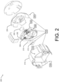
- FIG. 2 illustrates a magnified, exploded view 200 of an assembly including the main PCB thermal-control subsystem 110 of FIG. 1 .
- the assembly includes a main PCB 202 that is populated with an SoC IC device 204 and one or more memory IC device(s) 206, such as one or more DDR memory IC devices.
- the SoC IC device 204 and the one or more memory IC device(s) 206 are mounted to a first surface 208 of the main PCB 202.
- the SoC IC device 204 and the one or more memory IC device(s) 206 may be mounted to the first surface 208 of the main PCB 202 using surface mount (SMT) techniques that include soldering leads of the respective devices to electrical interconnect pads on the main PCB 202 and/or underfilling.
- SMT surface mount
- the main PCB 202 in some instances, may be a multi-layer PCB that includes multiple layers of electrical traces separated by multiple, corresponding layers of one or more dielectric materials.
- FIG. 2 also illustrates details of the main PCB thermal-control subsystem 110.
- the main PCB thermal-control subsystem 110 includes a first TIM 210 (e.g., an SoC IC device topside TIM), second TIM(s) 212 (e.g., memory IC device topside TIM(s)), and a first heat sink 214 (e.g., a front heat sink).
- the first TIM 210 and the second TIM(s) 212 may be located between, and serve as a thermal conduction path between, the first heat sink 214 and respective surfaces ( e.g ., respective topside surfaces) of the SoC IC device 204 and the memory IC device(s) 206.
- the first heat sink 214 may be die-cast and include, for example, an aluminum material such as AL1100. Furthermore, the first heat sink 214 may be positioned such that a perimeter surface 216 (e.g., an exterior surface) of the first heat sink 214 is in direct physical and thermal contact with a housing (e.g., an interior surface of a housing component of the security camera 102 of FIG. 1 ).
- the first heat sink 214 may also include one or more flange(s) 218 configured for multiple uses. For instance, the one or more flange(s) 218 may act as alignment guides to insert and assemble the first heat sink 214 into a housing of a security camera.
- the one or more flange(s) 218 may improve heat transfer (e.g ., thermal conduction) between the first heat sink 214 and the housing. Furthermore, the one or more flange(s) 218 may provide additional surface area to conduct additional heat to the housing.
- first heat sink 214 is illustrated as generally cylindrical in shape ( e.g ., having a generally round or oval cross-section), other shapes are possible. For instance, if a housing of a security camera including the first heat sink were of a cuboid shape, the first heat sink 214 could have a square or rectangular cross-section.
- a third TIM 220 (e.g., an SoC IC device backside TIM), as illustrated in FIG. 2 , is located between a second surface 222 of the main PCB 202 and a second heat sink 224 (e.g., a rear heat sink) having a generally concave shape.
- the third TIM 220 serves as a thermal conduction path between the second surface 222 of the main PCB 202 and the second heat sink 224.
- the main PCB thermal-control subsystem 110 may include different combinations of materials.
- the first TIM 210 and the second TIM(s) 212 may be made up of a gel material with a high thermal conductivity (measured in W/(m•K)) and include a silicone-rubber material injected with nanoparticles such as aluminum, beryllium-nitride, and so on.
- the third TIM 220 may include a thermal pad material. Examples of the thermal pad material include a preformed solid material that is silicone-based or paraffin wax-based.
- the second heat sink 224 may be a stamped heat sink formed using an aluminum-alloy material, such as AL1100.
- the second heat sink 224 may include one or more flange(s) 226 and/or bends that form a cavity or recessed area within the second heat sink 224 to receive and support the main PCB 202 (e.g., an outline or shape of the main PCB 202).
- the one or more flange(s) 226 may include a lip or a rib along an outer rim, which may enable the second heat sink 224 to be secured to (e.g., clip to) the first heat sink 214, thereby forming a cavity to house the main PCB 202.
- the one or more flange(s) 226 may contribute to improvements in performance of the main PCB thermal-control subsystem 110 by aligning surfaces for heat transfer (e.g ., thermal conduction) between the second heat sink 224 and a housing (e.g ., an interior surface of a housing component of the security camera 102 of FIG. 1 ). Furthermore, the one or more flange(s) 226 may provide additional surface area to conduct additional heat to the housing.
- the main PCB thermal-control subsystem 110 includes TIMs (e.g., the first TIM 210, the second TIM(s) 212, and the third TIM 220) having high thermal conductivity (e.g ., thermal gels and/or thermal pads) to transfer heat generated by the SoC IC device 204 and/or the memory IC device(s) 206.
- the main PCB thermal-control subsystem 110 transfers the heat using two different paths that include heat sinks with high thermal conductive properties (e.g ., a first path that includes the first heat sink 214 and a second path that includes the second heat sink 224).
- the main PCB thermal-control subsystem 110 in general, may contribute to maintaining multiple thermal zones of a security camera at or below respective, prescribed temperature thresholds.
- FIG. 3 illustrates example details 300 of heat flow distribution through the first heat sink 214 of FIG. 2 .
- the first heat sink 214 may have a generally cylindrical shape.
- An area of the perimeter surface 216 of the first heat sink 214 may be sized for a specific heat transfer performance.
- the area of the perimeter surface 216 may be sized to transfer a first portion 302 of heat through a front region 304 of the first heat sink 214 and a second portion 306 through the perimeter surface 216.
- the first portion 302 may be transferred using a convection and/or radiation heat transfer mechanism, while the second portion 306 may be transferred using a conduction heat transfer mechanism.
- heat transfer may include the first portion 302 being 65% of a heat load and the second portion 306 being 35% of the heat load.
- the surface area of the perimeter surface 216 may be sized to maintain a temperature of a thermal zone within a prescribed temperature threshold while a combined heat load (e.g., the solar heat load 104 and the internal heat load 106 of FIG. 1 ) is exuded upon a security camera that includes the first heat sink 214.
- distribution e.g ., portions of heat
- direction of heat flow through the first heat sink 214 may vary.
- Such different instances may include, for example, different magnitudes of heat loads (e.g ., different magnitudes of the solar heat load 104 and the internal heat load 106) as well as different ambient conditions surrounding a home-security camera including the first heat sink 214.
- different sizes (e.g ., respective surface areas) of the one more flange(s) 218 may alter or change respective magnitudes of the first portion 302 of the heat and the second portion 306 of the heat.
- respective locations of the one or more flange(s) 218 may impact respective magnitudes of the first portion 302 of the heat and the second portion 306 of the heat.
- the one or more flange(s) 218 may transfer heat using thermal conduction, thermal convection, and/or thermal radiation heat transfer mechanisms.
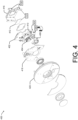
- FIG. 4 illustrates a magnified, exploded view 400 of an assembly including the sensor PCB thermal-control subsystem 112 of FIG. 1 .
- the assembly includes a sensor PCB 402 that is populated with an image sensor IC device 404 and a PIR sensor IC device 406.
- the image sensor IC device 404 and the PIR sensor IC device 406 are mounted to a first surface 408 of the sensor PCB 402.
- the image sensor IC device 404 and the PIR sensor IC device 406 may be mounted to the first surface 408 of the sensor PCB 402 using SMT techniques that include soldering leads of the respective devices to electrical interconnect pads on the sensor PCB 402 and underfilling.
- the sensor PCB 402 may be a multi-layer PCB that includes multiple layers of electrical traces separated by multiple, corresponding layers of one or more dielectric materials.
- the sensor PCB 402 may be further enhanced with separate, respective ground planes for the image sensor IC device 404 and the PIR sensor IC device 406.
- the respective ground planes may be thermally separated by a slot 410 in the sensor PCB 402 that reduces heat transfer between the image sensor IC device 404 and the PIR sensor IC device 406.
- the slot 410 may have a length that is an order of magnitude greater than a width of the slot (e.g., the length of the slot 410 may be 10 ⁇ the width of the slot 410) so that thermal separation ( e.g ., thermal resistance) is increased.
- the respective ground planes of the image sensor IC device 404 and the PIR sensor IC device 406 may be formed from a material that has a high thermal conductivity (e.g ., a copper material).
- FIG. 4 also illustrates a fourth TIM 412.
- the fourth TIM 412 may be located between a second surface 414 of the sensor PCB 402 (e.g., the second surface 414 that is opposite from the first surface 408 of the sensor PCB 402) and serve as a thermal conduction path between the second surface 414 of the sensor PCB 402 and a heat spreader 416.
- the heat spreader 416 may be stamped and fit within a generally rectangular outline.
- the heat spreader 416 may include for example, an aluminum material such as AL1100.
- the heat spreader 416 may include one or more flanges and/or bends 316 that form a cavity or a recessed area within the heat spreader 416 to receive and support the sensor PCB 402 (e.g., an outline or shape of the sensor PCB 402).
- the one or more flange(s) and/or bend(s) 418 may align the sensor PCB 402 to the heat spreader 416 to improve thermal contact between features of the sensor PCB 402 and the heat spreader 416, thereby improving heat transfer ( e.g.
- thermal conduction between the sensor PCB 402 and the heat spreader 416.
- the one or more flange(s) and/or bend(s) 418 may improve thermal performance of the sensor PCB by providing additional surface area for conduction and/or convection of heat from the heat spreader 416.
- a security camera may include an infrared light emitting diode (IRLED) board 318 and a cover 320 that impact heat flowing through the security camera.
- IRLED infrared light emitting diode
- the cover 320 may include notches and/or other features to which flanges of the heat spreader 416 may connect (e.g., clip).
- FIG. 5 illustrates example details 500 of multiple thermal zones controlled by the thermal-control system 108, including thermal zones controlled by the main PCB thermal-control subsystem 110 combined with the sensor PCB thermal-control subsystem 112.
- the multiple thermal zones include a first thermal zone 502 having the SoC IC device 204.
- the SoC IC device 204 may execute machine-learning algorithms and process images while the security camera is in a CVR mode to generate a portion of an internal heat load.
- the first thermal zone 502 may have a first prescribed temperature threshold corresponding to an allowable junction temperature of a diode within the SoC IC device 204 under the high thermal-loading condition ( e.g ., when both the solar heat load 104 and the internal heat load 106 are exuding heat upon a security camera such as the security camera 102 of FIG. 1 ).
- the first prescribed temperature threshold may be approximately 100 degrees Celsius (°C).
- the thermal-control system 108 may transfer and spread heat to maintain the first thermal zone 502 at or below the first prescribed temperature threshold (e.g ., the junction temperature of a diode within the SoC IC device 204 may be maintained at or below 72 °C under the high thermal-loading condition).
- the multiple thermal zones may also include a second thermal zone 504 that includes the one or more memory IC device(s) 206.
- the one or more memory IC device(s) 206 may be mounted to (and share) the first surface 208 of the main PCB 202.
- the second thermal zone 504 may have a second prescribed temperature threshold corresponding to an allowable junction temperature of the memory IC device(s) 206.
- the second prescribed temperature threshold may be approximately 85 °C.
- the thermal-control system 108 may concurrently transfer and spread heat to maintain the second thermal zone 504 at or below the second prescribed temperature threshold (e.g ., the allowable junction temperature of the memory IC device(s) 206 may be maintained at or below 85 °C under the high thermal-loading condition).
- a third thermal zone 506 that includes a battery 508 may also be part of the multiple thermal zones.
- the battery 508 may power the security camera 102 in the event another power source to the security camera 102 is interrupted.
- the third thermal zone 506 may have a third prescribed temperature threshold corresponding to an allowable temperature of the battery 508.
- the third prescribed temperature threshold may be approximately 80 °C.
- the thermal-control system 108 may concurrently transfer and spread heat to maintain the third thermal zone 506 at or below the third prescribed temperature threshold (e.g ., the allowable temperature of the battery 508 may be maintained at or below 80 °C under the high thermal-loading condition).
- the multiple thermal zones may also include a fourth thermal zone 510 that includes the image sensor IC device 404 (not visible in FIG. 5 ).
- the image sensor IC device 404 may be mounted to the first surface 408 of the sensor PCB 402 (not visible in FIG. 5 ).
- the fourth thermal zone 510 may have a fourth prescribed temperature threshold corresponding to an allowable junction temperature of a diode within the image sensor IC device 404.
- the fourth prescribed temperature threshold may be approximately 85 °C.
- the thermal-control system 108 may concurrently transfer and spread heat to maintain the fourth thermal zone 510 at or below the fourth prescribed temperature threshold (e.g. , the junction temperature of the diode within the image sensor IC device 404 may be maintained at or below 85 °C under the high thermal-loading condition).
- a fifth thermal zone 512 that includes the PIR sensor IC device 406 may be included in the multiple thermal zones.
- the PIR sensor IC device 406 may detect motion near a security camera and, like the image sensor IC device 404, be mounted to the first surface 408 of the sensor PCB 402.
- the fifth thermal zone 512 may have a fifth prescribed temperature threshold corresponding to an allowable junction temperature of a diode within the PIR sensor IC device 406 (not visible in FIG. 1 ).
- the fifth prescribed temperature threshold may be approximately 80 °C.
- the thermal-control system 108 may concurrently transfer and spread heat to maintain the fifth thermal zone 512 at or below the fifth prescribed temperature threshold (e.g. , the junction temperature of a diode within the PIR sensor IC device 406 may be maintained at or below 80 °C under the high thermal-loading condition).
- the multiple thermal zones also include a sixth thermal zone 514 that includes a housing component 516.
- the housing component 516 may house devices and subassemblies of a security camera ( e.g. , the security camera 102 of FIG. 1 ).
- the sixth thermal zone 514 may have a sixth prescribed temperature threshold corresponding to an allowable ergonomic touch temperature of the housing component 516.
- the sixth prescribed temperature threshold may be approximately 77 °C.
- the thermal-control system 108 may concurrently transfer and spread heat to maintain the sixth thermal zone 514 at or below the sixth prescribed temperature threshold (e.g. , the allowable ergonomic touch temperature of the housing component 516 may be maintained at or below 77 °C under the high thermal-loading condition).
- the thermal-control system 108 may concurrently transfer and spread the heat (e.g. , solar heat load 104, internal heat load 106 of FIG. 1 ) throughout a security camera ( e.g. , the security camera 102 of FIG. 1 ) using heat transfer modes that include conduction, convection, and/or radiation.
- the heat may subsequently be dissipated through exterior surfaces of the security camera (e.g. , exterior surfaces of the housing component 516) to concurrently maintain temperatures of the six thermal zones (502, 504, 506, 510, 512, and 514) at or below respective prescribed temperature thresholds.
- the thermal-control system 108 may include the main PCB thermal-control subsystem 110 having heat transfer mechanisms that contribute to transferring heat away from the SoC IC device 204.
- the main PCB thermal-control subsystem 110 may include the first TIM 210 (e.g., the SoC IC device topside TIM), the one or more second TIM(s) 212 (e.g., the memory IC device topside TIM(s)), and the first heat sink 214 (e.g., the front heat sink).
- the first heat sink 214 may be located between the battery 508 and the main PCB 202.
- the first TIM 210 may be located between, and serve as a thermal conduction path between, the SoC IC device 204 and the first heat sink 214.
- the second TIM(s) 212 may be located between, and serve as a thermal conduction path between, the first heat sink 214 and the memory IC device(s) 206.
- the main PCB thermal-control subsystem 110 may also include the third TIM 220 (e.g., the SoC IC device backside TIM) and the second heat sink 224 (e.g., a rear heat sink).
- the third TIM 220 may be located between the second surface 222 of the main PCB 202 and the second heat sink 224.
- the third TIM 220 may have a footprint that mirrors and approximates an outline of the SoC IC device 204.
- the main PCB thermal-control subsystem 110 may include different combinations of materials.
- the first TIM 210 and the second TIM(s) 212 may be made up of a gel material with a high thermal conductivity (measured in W/(m • K)) and include a silicone-rubber material injected with nanoparticles such as aluminum, beryllium-nitride, and so on.
- the third TIM 220 may include a thermal pad material. Examples of the thermal pad material include a preformed solid material that is silicone-based or paraffin wax-based.
- the thermal-control system 108 may include the sensor PCB thermal-control subsystem 112 having heat transfer mechanisms that contribute to transferring heat away from the image sensor IC device 404 and/or the PIR sensor IC device 406.
- the sensor PCB thermal-control subsystem 112 may include the heat spreader 416 and the fourth TIM 412 of FIG. 4 (not visible in FIG. 5 ).
- the fourth TIM 412 may be located between the second surface 414 of the sensor PCB 402 and the heat spreader 416 and serve as a thermal conduction path between the second surface 414 of the sensor PCB 402 and the heat spreader 416.
- the sensor PCB thermal-control subsystem 112 may include different combinations of materials.
- the fourth TIM 412 may be made up of a gel material with a high thermal conductivity and include a silicone-rubber material injected with nanoparticles made of aluminum, beryllium-nitride, and so on.
- the thermal-control system 108 is a passive thermal-control system. As implemented, the thermal-control system 108 does not require or use active or powered fans or pumps to concurrently maintain temperatures of the six thermal zones (502, 504, 506, 510, 512, and 514) at or below prescribed temperature thresholds.
- the main PCB thermal-control subsystem 110 may transfer a first quantity of heat to the housing component 516
- the sensor PCB thermal-control subsystem 112 may transfer a second quantity of heat to the housing component 516.
- Respective quantities of heat e.g., the first quantity of heat and the second quantity of heat
- the first heat sink 214 may include a cavity that supports or houses a battery 508.
- the thermal-control system 108 may include a thermal foam material 518 having a low thermal conductivity to inhibit or prevent heat (e.g., heat from the SoC IC device 204) from transferring through the first heat sink 214 to the battery 508. Preventing heat transfer to the battery 508 may, in some instances, prevent the battery 508 from swelling and damaging the first heat sink 214.
- Example 1 A thermal-control system (108) for a security camera (102) comprising a housing, the thermal-control system (108) comprising: a first thermal-control subsystem (110), the first thermal-control subsystem (110) configured to transfer a first quantity of heat to the housing of the security camera, the first thermal-control subsystem (110) including: a first thermal interface material (210), the first thermal interface material located (210) between a system-on-chip integrated circuit device (204) of the security camera (102) and a first heat sink (214) of the thermal-control system (108), the system-on-chip integrated circuit device (204) mounted to a first surface (208) of a first printed circuit board (202) of the security camera (102); a second thermal interface material (212), the second thermal interface material (212) located between a memory integrated circuit device (206) and the first heat sink (214), the memory integrated circuit device (206) mounted to the first surface (208) of the first printed circuit board (202); and a third thermal interface material (220), the third thermal interface material (220) located between a second surface (222)
- Example 2 The thermal-control system (108) of example 1, wherein the first heat sink (214) has a generally cylindrical shape, the second heat sink (224) has a generally concave shape, and the heat spreader (416) has a generally rectangular outline.
- Example 3 The thermal-control system (108) of example 1 or 2, wherein: the first thermal interface material (210) includes a silicone-rubber material injected with nanoparticles.
- Example 4 The thermal-control system of any one of the preceding examples, wherein the first heat sink (214) is a die-cast heatsink that includes an aluminum material.
- Example 5 The thermal-control system (108) of any one of the preceding examples, wherein the second heat sink (224) is a stamped heat sink that includes an aluminum-alloy material.
- Example 6 The thermal-control system (108) of any one of examples 1 to 5, wherein the first heat sink (214) includes a cavity that supports a battery.
- Example 7 The thermal-control system (108) of example 5, wherein an exterior surface of the first heat sink (214) is in direct physical and thermal contact with an interior surface of the housing.
- Example 8 The thermal-control system of any one of the preceding examples, further comprising a thermal foam material (518) located between the first heat sink (214) and a battery (508).
- Example 9 The thermal-control system (108) of any one of the preceding examples, wherein the third thermal interface material (220) includes a thermal pad material.
- Example 10 The thermal-control system (108) of example 9, wherein the thermal pad material includes a paraffin wax-based material.
- Example 11 The thermal-control system (108) of example 9, wherein the thermal pad material includes a silicone material.
- Example 12 The thermal-control system (108) of any one of the preceding examples, wherein the fourth thermal interface material (412) includes a gel material.
- Example 13 The thermal-control system of example 12, wherein the gel material includes a silicone-rubber material injected with nanoparticles.
- Example 14 A security camera (102) comprising: a system-on-chip integrated circuit device (204) that is mounted to a first surface (208) of a first printed circuit board (202); a memory integrated circuit device (206) that is mounted to the first surface (208) of the first printed circuit board (202); and a thermal-control system (108) of any one of examples 1 to 7.
- Example 15 The security camera (102) of example 14, further comprising: a passive infrared sensor integrated circuit device (406) mounted to a first surface (408) of a second printed circuit board (402); and an image sensor integrated circuit device (404) mounted to the first surface (408) of the second printed circuit board (402).
- a passive infrared sensor integrated circuit device 406 mounted to a first surface (408) of a second printed circuit board (402); and an image sensor integrated circuit device (404) mounted to the first surface (408) of the second printed circuit board (402).
Landscapes
- Physics & Mathematics (AREA)
- Engineering & Computer Science (AREA)
- General Physics & Mathematics (AREA)
- Multimedia (AREA)
- Signal Processing (AREA)
- Microelectronics & Electronic Packaging (AREA)
- Thermal Sciences (AREA)
- Aviation & Aerospace Engineering (AREA)
- Electromagnetism (AREA)
- Studio Devices (AREA)
- Accessories Of Cameras (AREA)
- Burglar Alarm Systems (AREA)
- Camera Bodies And Camera Details Or Accessories (AREA)
- Details Of Indoor Wiring (AREA)
- Communication Cables (AREA)
- Insertion, Bundling And Securing Of Wires For Electric Apparatuses (AREA)
Abstract
Description
- Security cameras are becoming a popular addition to home security systems. A security camera may be battery-powered and include multiple integrated circuit (IC) devices, such as a passive infrared (PIR) sensor IC device that detects motion and an image sensor IC device that captures images. The security camera may also include a system-on-chip (SoC) IC device that executes a machine-learning algorithm.
- The security camera may, in some instances, include a thermal-control system fabricated using a stamped sheet metal structure that can dissipate heat from the SoC IC device during a low thermal-loading condition, such as when the security camera is operating in an event-based recording (EBR) mode that is triggered by a motion detected through the PIR sensor IC device. In such instances, the SoC IC device may dissipate heat at a rate of up to 2.5 Watts (W) for several seconds. In such an instance, the thermal-control system may be capable of dissipating the heat from the low thermal-loading condition to maintain a single prescribed temperature threshold across the multiple IC devices, effectively treating the security camera as a single thermal zone.
- However, under a high thermal-loading condition, such as when the security camera is operating in a continuous video recording (CVR) mode, the SoC IC device may dissipate heat at a rate of up to 2.5 W continually. Additionally, if the security camera is exposed to solar radiation, the high thermal-loading condition on the security camera may increase even further (e.g., increase further beyond 2.5 W). In such an instance, the thermal-control system may be inadequate to maintain the single prescribed temperature threshold across the multiple IC devices. The inability of the thermal-control system to dissipate heat from the security camera may result in (i) damage to one or more IC devices of the security camera and/or (ii) a housing of the security camera exceeding a prescribed ergonomic touch-temperature threshold.
- This document describes a thermal-control system that is to be integrated into a security camera. The thermal-control system includes a combination of heatsinks and thermal interface materials (TIMs) with high thermal conductivities. The thermal-control system may transfer and spread energy from a high thermal-loading condition effectuated upon the security camera to concurrently maintain temperatures of multiple thermal zones on or within the security camera at or below prescribed temperature thresholds.
- In some aspects, a thermal-control system for a security camera is described. The thermal-control system includes a first thermal-control subsystem that is configured to transfer a first quantity of heat to a housing. The first thermal-control subsystem includes a first TIM that is located between an SoC IC device and a first heat sink, where the SoC IC device is mounted to a first surface of a first printed circuit board (PCB). The first thermal-control subsystem also includes a second TIM that is located between a memory IC device, such as a double-data rate (DDR) memory IC device, and the first heat sink. The memory IC device, like the SoC IC device, is mounted to the first surface of the PCB. The first thermal-control subsystem also includes a third TIM that is located between a second surface of the first PCB and a second heat sink, where the second surface of the first PCB is opposite the first surface of the first PCB.
- The thermal-control system for the security camera, as described, also includes a second thermal-control subsystem that is configured to transfer a second quantity of heat to the housing. The second thermal-control subsystem includes a fourth TIM that is located between a second surface of a second PCB and a heat spreader. The second surface of the second PCB is opposite a first surface of the second PCB to which a passive infrared sensor IC device and an image sensor IC device are mounted.
- In some other aspects, a security camera is described. The security camera includes an SoC IC device mounted to a surface of a PCB, a memory IC device mounted to the surface of the PCB, and a battery. The security camera also includes a thermal-control system configured to concurrently maintain temperatures through the security camera during a high thermal-loading condition. The thermal-control system is configured to concurrently maintain (i) a first temperature of a first thermal zone that includes the SoC IC device at or below a first prescribed temperature threshold, (ii) a second temperature of a second thermal zone that includes the memory IC device at or below a second prescribed temperature threshold, and (iii) a third temperature of a third thermal zone that includes the battery at or below a third prescribed temperature threshold.
- The details of one or more implementations are set forth in the accompanying drawings and the following description. Other features and advantages will be apparent from the description, the drawings, and the claims. This summary is provided to introduce subject matter that is further described in the Detailed Description. Accordingly, a reader should not consider the summary to describe essential features nor threshold the scope of the claimed subject matter.
- The details of one or more aspects of a thermal-control system for a security camera are described below. The use of the same reference numbers in different instances in the description and the figures indicate similar mechanisms:
-
FIG. 1 illustrates an example operating environment in which a thermal-control system for a security camera can be implemented. -
FIG. 2 illustrates a magnified, exploded view of an assembly including a main PCB thermal-control subsystem. -
FIG. 3 illustrates example details of heat flow distribution through a heat sink within a main PCB thermal-control subsystem. -
FIG. 4 illustrates a magnified, exploded view of an assembly including a sensor PCB thermal-control subsystem. -
FIG. 5 illustrates example details of multiple thermal zones controlled by a thermal-control system of a security camera. - This document describes a thermal-control system that is integrated into a security camera. The thermal-control system includes a combination of heatsinks and thermal interface materials (TIMs) with high thermal conductivities. The thermal-control system may transfer and spread energy from a high thermal-loading condition effectuated upon the security camera to concurrently maintain temperatures of multiple thermal zones on or within the security camera at or below prescribed temperature thresholds.
- While features and concepts of the described thermal-control system can be implemented in any number of different environments and devices, aspects are described in the context of the descriptions and examples below.
- Heat transfer, in general, is energy that is in transit due to a temperature difference. If one or more temperature differences exist across components of a system, such as the security camera, heat (e.g., energy in Joules) will transfer from higher temperature zones to lower temperature zones to minimize the temperature differences. There are several mechanisms for heat transfer across the components of a system to minimize temperature differences, including convection, radiation, and conduction.
- Convection, or heat transfer from a surface due to movement of molecules within fluids such as gases and liquids, can be quantified by equation (1) below:

- For equation (1), qconv represents a rate of heat transfer from a surface through convection (e.g., in Joules per second or Watts (W)), h represents a convection heat transfer coefficient (e.g., in W per meter squared (W/m2)), Ts represents a temperature of a surface (e.g., in Kelvin (K) or degrees Celsius (°C)), and T ∞ represents a temperature of a fluid (e.g., in K or °C) to which the surface is exposed. The term A represents the area of a surface (e.g., in m2).
- Radiation, or heat transfer from a surface through electromagnetic radiation, can be quantified by equation (2) below:

- For equation (2), qrad represents a rate of heat transfer through radiation (e.g., in W), ε represents emissivity (dimensionless), σ represents the Stefen-Boltzmann constant (e.g., σ = 5.67 × 10- 8 W/(m2•K4)), Ts represents a temperature of a surface (e.g., in K or °C), and Tsurr represents a temperature of surroundings of the surface (e.g., in K or °C). The term A represents an area of the surface (e.g., in m2).
- Conduction, or heat transfer through a solid body through atomic and molecular activity, can be quantified by equation (3) below:

- For equation (3), qcond represents a rate of heat transfer in a solid material through conduction (e.g., in W), k represents a thermal conductivity of the solid material (e.g., in W/(m•K)), and dT/dx represents a temperature gradient through the solid material (e.g., in K/m or °C/m). The term A represents a cross-sectional area of the solid material (e.g., in m2).
- For a security camera, heat transfer between components may occur using one or more of the heat transfer mechanisms described above. In general, and in accordance with equations (1) and (2), heat transfer can be varied by increasing or decreasing surface areas for convection and/or radiation within the security camera (e.g., increasing or decreasing surface areas of heat sinks and/or heat spreading mechanisms).
- Furthermore, and in accordance with equation (3), heat transfer can be varied by choosing one or more TIMs having specific thermal conductivities. Through careful design of heat sinks and the use of TIMs having the specific thermal conductivities, a thermal-control system of the security camera can concurrently maintain temperatures of different thermal zones at or below different prescribed temperature thresholds during a high thermal-loading condition.
-
FIG. 1 illustrates anexample operating environment 100 in which a thermal-control system for a security camera can be implemented. In theoperating environment 100, a solar source (e.g., the sun) is radiating a solar heat load 104 (e.g., qs ) onto at least one exterior surface of thesecurity camera 102. Also, in the operatingenvironment 100, at least one electronic device (e.g., at least one IC device) is generating an internal heat load 106 (e.g., qi ) within thesecurity camera 102. The operatingenvironment 100 may include a 1000 W/m2solar heat load 104 and a 2.5 Winternal heat load 106. - As will be described in greater detail in figures below, the
security camera 102 includes a thermal-control system 108. The thermal-control system 108 may include one or more thermal-control subsystems. For instance, the thermal-control system 108 may include a main PCB thermal-control subsystem 110 having heat transfer mechanisms that contribute to transferring heat from a main PCB populated with an SoC IC device and one or more memory IC devices to a housing of thesecurity camera 102. The thermal-control system 108 may also include a sensor PCB thermal-control subsystem 112 having other heat transfer mechanisms that contribute to transferring heat from a sensor PCB populated with a PIR sensor IC device and an image sensor IC device to the housing of the security camera. - The thermal-
control system 108 may effectuate transfer of heat (e.g., thesolar heat load 104 plus theinternal heat load 106 as realized by the security camera 102) for heat dissipation 114 (e.g., qd ) to the operatingenvironment 100. In some instances, the thermal-control system may also concurrently maintain temperatures of multiple thermal zones within thesecurity camera 102 at or below multiple, different prescribed temperature thresholds. -
FIG. 2 illustrates a magnified, explodedview 200 of an assembly including the main PCB thermal-control subsystem 110 ofFIG. 1 . As illustrated, the assembly includes amain PCB 202 that is populated with anSoC IC device 204 and one or more memory IC device(s) 206, such as one or more DDR memory IC devices. - The
SoC IC device 204 and the one or more memory IC device(s) 206 are mounted to afirst surface 208 of themain PCB 202. TheSoC IC device 204 and the one or more memory IC device(s) 206 may be mounted to thefirst surface 208 of themain PCB 202 using surface mount (SMT) techniques that include soldering leads of the respective devices to electrical interconnect pads on themain PCB 202 and/or underfilling. Themain PCB 202, in some instances, may be a multi-layer PCB that includes multiple layers of electrical traces separated by multiple, corresponding layers of one or more dielectric materials. -
FIG. 2 also illustrates details of the main PCB thermal-control subsystem 110. The main PCB thermal-control subsystem 110 includes a first TIM 210 (e.g., an SoC IC device topside TIM), second TIM(s) 212 (e.g., memory IC device topside TIM(s)), and a first heat sink 214 (e.g., a front heat sink). Thefirst TIM 210 and the second TIM(s) 212 may be located between, and serve as a thermal conduction path between, thefirst heat sink 214 and respective surfaces (e.g., respective topside surfaces) of theSoC IC device 204 and the memory IC device(s) 206. - The
first heat sink 214 may be die-cast and include, for example, an aluminum material such as AL1100. Furthermore, thefirst heat sink 214 may be positioned such that a perimeter surface 216 (e.g., an exterior surface) of thefirst heat sink 214 is in direct physical and thermal contact with a housing (e.g., an interior surface of a housing component of thesecurity camera 102 ofFIG. 1 ). Thefirst heat sink 214 may also include one or more flange(s) 218 configured for multiple uses. For instance, the one or more flange(s) 218 may act as alignment guides to insert and assemble thefirst heat sink 214 into a housing of a security camera. By aligning the surfaces (e.g., theperimeter surface 216 to an interior surface of the housing), the one or more flange(s) 218 may improve heat transfer (e.g., thermal conduction) between thefirst heat sink 214 and the housing. Furthermore, the one or more flange(s) 218 may provide additional surface area to conduct additional heat to the housing. - Although the
first heat sink 214 is illustrated as generally cylindrical in shape (e.g., having a generally round or oval cross-section), other shapes are possible. For instance, if a housing of a security camera including the first heat sink were of a cuboid shape, thefirst heat sink 214 could have a square or rectangular cross-section. - A third TIM 220 (e.g., an SoC IC device backside TIM), as illustrated in
FIG. 2 , is located between asecond surface 222 of themain PCB 202 and a second heat sink 224 (e.g., a rear heat sink) having a generally concave shape. Thethird TIM 220 serves as a thermal conduction path between thesecond surface 222 of themain PCB 202 and thesecond heat sink 224. - The main PCB thermal-
control subsystem 110 may include different combinations of materials. For example, thefirst TIM 210 and the second TIM(s) 212 may be made up of a gel material with a high thermal conductivity (measured in W/(m•K)) and include a silicone-rubber material injected with nanoparticles such as aluminum, beryllium-nitride, and so on. As another example, thethird TIM 220 may include a thermal pad material. Examples of the thermal pad material include a preformed solid material that is silicone-based or paraffin wax-based. - In some instances, the
second heat sink 224 may be a stamped heat sink formed using an aluminum-alloy material, such as AL1100. Thesecond heat sink 224 may include one or more flange(s) 226 and/or bends that form a cavity or recessed area within thesecond heat sink 224 to receive and support the main PCB 202 (e.g., an outline or shape of the main PCB 202). When assembled, the one or more flange(s) 226 may include a lip or a rib along an outer rim, which may enable thesecond heat sink 224 to be secured to (e.g., clip to) thefirst heat sink 214, thereby forming a cavity to house themain PCB 202. Furthermore, and in some instances, the one or more flange(s) 226 may contribute to improvements in performance of the main PCB thermal-control subsystem 110 by aligning surfaces for heat transfer (e.g., thermal conduction) between thesecond heat sink 224 and a housing (e.g., an interior surface of a housing component of thesecurity camera 102 ofFIG. 1 ). Furthermore, the one or more flange(s) 226 may provide additional surface area to conduct additional heat to the housing. - In general, the main PCB thermal-
control subsystem 110, as detailed inFIG. 2 , includes TIMs (e.g., thefirst TIM 210, the second TIM(s) 212, and the third TIM 220) having high thermal conductivity (e.g., thermal gels and/or thermal pads) to transfer heat generated by theSoC IC device 204 and/or the memory IC device(s) 206. The main PCB thermal-control subsystem 110 transfers the heat using two different paths that include heat sinks with high thermal conductive properties (e.g., a first path that includes thefirst heat sink 214 and a second path that includes the second heat sink 224). The main PCB thermal-control subsystem 110, in general, may contribute to maintaining multiple thermal zones of a security camera at or below respective, prescribed temperature thresholds. -
FIG. 3 illustrates example details 300 of heat flow distribution through thefirst heat sink 214 ofFIG. 2 . - As illustrated, the
first heat sink 214 may have a generally cylindrical shape. An area of theperimeter surface 216 of thefirst heat sink 214 may be sized for a specific heat transfer performance. As an example, the area of theperimeter surface 216 may be sized to transfer afirst portion 302 of heat through afront region 304 of thefirst heat sink 214 and asecond portion 306 through theperimeter surface 216. In such an instance, thefirst portion 302 may be transferred using a convection and/or radiation heat transfer mechanism, while thesecond portion 306 may be transferred using a conduction heat transfer mechanism. - As an example, heat transfer may include the
first portion 302 being 65% of a heat load and thesecond portion 306 being 35% of the heat load. The surface area of theperimeter surface 216 may be sized to maintain a temperature of a thermal zone within a prescribed temperature threshold while a combined heat load (e.g., thesolar heat load 104 and theinternal heat load 106 ofFIG. 1 ) is exuded upon a security camera that includes thefirst heat sink 214. - Note that for different instances, distribution (e.g., portions of heat) and direction of heat flow through the
first heat sink 214 may vary. Such different instances may include, for example, different magnitudes of heat loads (e.g., different magnitudes of thesolar heat load 104 and the internal heat load 106) as well as different ambient conditions surrounding a home-security camera including thefirst heat sink 214. - In some instances, different sizes (e.g., respective surface areas) of the one more flange(s) 218 may alter or change respective magnitudes of the
first portion 302 of the heat and thesecond portion 306 of the heat. Furthermore, respective locations of the one or more flange(s) 218 may impact respective magnitudes of thefirst portion 302 of the heat and thesecond portion 306 of the heat. The one or more flange(s) 218 may transfer heat using thermal conduction, thermal convection, and/or thermal radiation heat transfer mechanisms. -
FIG. 4 illustrates a magnified, explodedview 400 of an assembly including the sensor PCB thermal-control subsystem 112 ofFIG. 1 . As illustrated, the assembly includes asensor PCB 402 that is populated with an imagesensor IC device 404 and a PIRsensor IC device 406. - The image
sensor IC device 404 and the PIRsensor IC device 406 are mounted to afirst surface 408 of thesensor PCB 402. The imagesensor IC device 404 and the PIRsensor IC device 406 may be mounted to thefirst surface 408 of thesensor PCB 402 using SMT techniques that include soldering leads of the respective devices to electrical interconnect pads on thesensor PCB 402 and underfilling. - The
sensor PCB 402, in some instances, may be a multi-layer PCB that includes multiple layers of electrical traces separated by multiple, corresponding layers of one or more dielectric materials. Thesensor PCB 402 may be further enhanced with separate, respective ground planes for the imagesensor IC device 404 and the PIRsensor IC device 406. - The respective ground planes may be thermally separated by a
slot 410 in thesensor PCB 402 that reduces heat transfer between the imagesensor IC device 404 and the PIRsensor IC device 406. In some instances, theslot 410 may have a length that is an order of magnitude greater than a width of the slot (e.g., the length of theslot 410 may be 10 × the width of the slot 410) so that thermal separation (e.g., thermal resistance) is increased. Furthermore, the respective ground planes of the imagesensor IC device 404 and the PIRsensor IC device 406 may be formed from a material that has a high thermal conductivity (e.g., a copper material). -
FIG. 4 also illustrates afourth TIM 412. Thefourth TIM 412 may be located between asecond surface 414 of the sensor PCB 402 (e.g., thesecond surface 414 that is opposite from thefirst surface 408 of the sensor PCB 402) and serve as a thermal conduction path between thesecond surface 414 of thesensor PCB 402 and aheat spreader 416. - The
heat spreader 416 may be stamped and fit within a generally rectangular outline. Theheat spreader 416 may include for example, an aluminum material such as AL1100. Theheat spreader 416 may include one or more flanges and/or bends 316 that form a cavity or a recessed area within theheat spreader 416 to receive and support the sensor PCB 402 (e.g., an outline or shape of the sensor PCB 402). In some instances, the one or more flange(s) and/or bend(s) 418 may align thesensor PCB 402 to theheat spreader 416 to improve thermal contact between features of thesensor PCB 402 and theheat spreader 416, thereby improving heat transfer (e.g., thermal conduction) between thesensor PCB 402 and theheat spreader 416. Furthermore, the one or more flange(s) and/or bend(s) 418 may improve thermal performance of the sensor PCB by providing additional surface area for conduction and/or convection of heat from theheat spreader 416. - In some instances, other features of a security camera may indirectly impact the sensor PCB thermal-
control subsystem 112. For instance, a security camera may include an infrared light emitting diode (IRLED) board 318 and a cover 320 that impact heat flowing through the security camera. The cover 320 may include notches and/or other features to which flanges of theheat spreader 416 may connect (e.g., clip). -
FIG. 5 illustrates example details 500 of multiple thermal zones controlled by the thermal-control system 108, including thermal zones controlled by the main PCB thermal-control subsystem 110 combined with the sensor PCB thermal-control subsystem 112. - The multiple thermal zones include a first
thermal zone 502 having theSoC IC device 204. TheSoC IC device 204 may execute machine-learning algorithms and process images while the security camera is in a CVR mode to generate a portion of an internal heat load. - The first
thermal zone 502 may have a first prescribed temperature threshold corresponding to an allowable junction temperature of a diode within theSoC IC device 204 under the high thermal-loading condition (e.g., when both thesolar heat load 104 and theinternal heat load 106 are exuding heat upon a security camera such as thesecurity camera 102 ofFIG. 1 ). - As an example, the first prescribed temperature threshold may be approximately 100 degrees Celsius (°C). In such an instance, the thermal-
control system 108 may transfer and spread heat to maintain the firstthermal zone 502 at or below the first prescribed temperature threshold (e.g., the junction temperature of a diode within theSoC IC device 204 may be maintained at or below 72 °C under the high thermal-loading condition). - The multiple thermal zones may also include a second
thermal zone 504 that includes the one or more memory IC device(s) 206. Like theSoC IC device 204, the one or more memory IC device(s) 206 may be mounted to (and share) thefirst surface 208 of themain PCB 202. - The second
thermal zone 504 may have a second prescribed temperature threshold corresponding to an allowable junction temperature of the memory IC device(s) 206. As an example, the second prescribed temperature threshold may be approximately 85 °C. In such an instance, the thermal-control system 108 may concurrently transfer and spread heat to maintain the secondthermal zone 504 at or below the second prescribed temperature threshold (e.g., the allowable junction temperature of the memory IC device(s) 206 may be maintained at or below 85 °C under the high thermal-loading condition). - A third
thermal zone 506 that includes abattery 508 may also be part of the multiple thermal zones. Thebattery 508 may power thesecurity camera 102 in the event another power source to thesecurity camera 102 is interrupted. - The third
thermal zone 506 may have a third prescribed temperature threshold corresponding to an allowable temperature of thebattery 508. As an example, the third prescribed temperature threshold may be approximately 80 °C. In such an instance, the thermal-control system 108 may concurrently transfer and spread heat to maintain the thirdthermal zone 506 at or below the third prescribed temperature threshold (e.g., the allowable temperature of thebattery 508 may be maintained at or below 80 °C under the high thermal-loading condition). - The multiple thermal zones may also include a fourth
thermal zone 510 that includes the image sensor IC device 404 (not visible inFIG. 5 ). The imagesensor IC device 404 may be mounted to thefirst surface 408 of the sensor PCB 402 (not visible inFIG. 5 ). - The fourth
thermal zone 510 may have a fourth prescribed temperature threshold corresponding to an allowable junction temperature of a diode within the imagesensor IC device 404. As an example, the fourth prescribed temperature threshold may be approximately 85 °C. In such an instance, the thermal-control system 108 may concurrently transfer and spread heat to maintain the fourththermal zone 510 at or below the fourth prescribed temperature threshold (e.g., the junction temperature of the diode within the imagesensor IC device 404 may be maintained at or below 85 °C under the high thermal-loading condition). - A fifth
thermal zone 512 that includes the PIRsensor IC device 406 may be included in the multiple thermal zones. The PIRsensor IC device 406 may detect motion near a security camera and, like the imagesensor IC device 404, be mounted to thefirst surface 408 of thesensor PCB 402. - The fifth
thermal zone 512 may have a fifth prescribed temperature threshold corresponding to an allowable junction temperature of a diode within the PIR sensor IC device 406 (not visible inFIG. 1 ). As an example, the fifth prescribed temperature threshold may be approximately 80 °C. In such an instance, the thermal-control system 108 may concurrently transfer and spread heat to maintain the fifththermal zone 512 at or below the fifth prescribed temperature threshold (e.g., the junction temperature of a diode within the PIRsensor IC device 406 may be maintained at or below 80 °C under the high thermal-loading condition). - The multiple thermal zones also include a sixth
thermal zone 514 that includes ahousing component 516. Thehousing component 516 may house devices and subassemblies of a security camera (e.g., thesecurity camera 102 ofFIG. 1 ). The sixththermal zone 514 may have a sixth prescribed temperature threshold corresponding to an allowable ergonomic touch temperature of thehousing component 516. As an example, the sixth prescribed temperature threshold may be approximately 77 °C. In such an instance, the thermal-control system 108 may concurrently transfer and spread heat to maintain the sixththermal zone 514 at or below the sixth prescribed temperature threshold (e.g., the allowable ergonomic touch temperature of thehousing component 516 may be maintained at or below 77 °C under the high thermal-loading condition). - The thermal-
control system 108 may concurrently transfer and spread the heat (e.g.,solar heat load 104,internal heat load 106 ofFIG. 1 ) throughout a security camera (e.g., thesecurity camera 102 ofFIG. 1 ) using heat transfer modes that include conduction, convection, and/or radiation. The heat may subsequently be dissipated through exterior surfaces of the security camera (e.g., exterior surfaces of the housing component 516) to concurrently maintain temperatures of the six thermal zones (502, 504, 506, 510, 512, and 514) at or below respective prescribed temperature thresholds. - The thermal-
control system 108 may include the main PCB thermal-control subsystem 110 having heat transfer mechanisms that contribute to transferring heat away from theSoC IC device 204. The main PCB thermal-control subsystem 110 may include the first TIM 210 (e.g., the SoC IC device topside TIM), the one or more second TIM(s) 212 (e.g., the memory IC device topside TIM(s)), and the first heat sink 214 (e.g., the front heat sink). Thefirst heat sink 214 may be located between thebattery 508 and themain PCB 202. Thefirst TIM 210 may be located between, and serve as a thermal conduction path between, theSoC IC device 204 and thefirst heat sink 214. The second TIM(s) 212 may be located between, and serve as a thermal conduction path between, thefirst heat sink 214 and the memory IC device(s) 206. - The main PCB thermal-
control subsystem 110 may also include the third TIM 220 (e.g., the SoC IC device backside TIM) and the second heat sink 224 (e.g., a rear heat sink). Thethird TIM 220 may be located between thesecond surface 222 of themain PCB 202 and thesecond heat sink 224. In some instances, thethird TIM 220 may have a footprint that mirrors and approximates an outline of theSoC IC device 204. - The main PCB thermal-
control subsystem 110 may include different combinations of materials. For example, thefirst TIM 210 and the second TIM(s) 212 may be made up of a gel material with a high thermal conductivity (measured in W/(m•K)) and include a silicone-rubber material injected with nanoparticles such as aluminum, beryllium-nitride, and so on. As another example, thethird TIM 220 may include a thermal pad material. Examples of the thermal pad material include a preformed solid material that is silicone-based or paraffin wax-based. - The thermal-
control system 108 may include the sensor PCB thermal-control subsystem 112 having heat transfer mechanisms that contribute to transferring heat away from the imagesensor IC device 404 and/or the PIRsensor IC device 406. The sensor PCB thermal-control subsystem 112 may include theheat spreader 416 and thefourth TIM 412 ofFIG. 4 (not visible inFIG. 5 ). Thefourth TIM 412 may be located between thesecond surface 414 of thesensor PCB 402 and theheat spreader 416 and serve as a thermal conduction path between thesecond surface 414 of thesensor PCB 402 and theheat spreader 416. - The sensor PCB thermal-
control subsystem 112 may include different combinations of materials. For example, thefourth TIM 412 may be made up of a gel material with a high thermal conductivity and include a silicone-rubber material injected with nanoparticles made of aluminum, beryllium-nitride, and so on. - The thermal-
control system 108, including the main PCB thermal-control subsystem 110 and the sensor PCB thermal-control subsystem 112, is a passive thermal-control system. As implemented, the thermal-control system 108 does not require or use active or powered fans or pumps to concurrently maintain temperatures of the six thermal zones (502, 504, 506, 510, 512, and 514) at or below prescribed temperature thresholds. - In general, the main PCB thermal-
control subsystem 110 may transfer a first quantity of heat to thehousing component 516, and the sensor PCB thermal-control subsystem 112 may transfer a second quantity of heat to thehousing component 516. Respective quantities of heat (e.g., the first quantity of heat and the second quantity of heat) may vary based on changing thermal loads and/or ambient conditions. - In certain instances, the
first heat sink 214 may include a cavity that supports or houses abattery 508. In such an instance, the thermal-control system 108 may include athermal foam material 518 having a low thermal conductivity to inhibit or prevent heat (e.g., heat from the SoC IC device 204) from transferring through thefirst heat sink 214 to thebattery 508. Preventing heat transfer to thebattery 508 may, in some instances, prevent thebattery 508 from swelling and damaging thefirst heat sink 214. - In the following, several examples will be described.
- Example 1: A thermal-control system (108) for a security camera (102) comprising a housing, the thermal-control system (108) comprising: a first thermal-control subsystem (110), the first thermal-control subsystem (110) configured to transfer a first quantity of heat to the housing of the security camera, the first thermal-control subsystem (110) including: a first thermal interface material (210), the first thermal interface material located (210) between a system-on-chip integrated circuit device (204) of the security camera (102) and a first heat sink (214) of the thermal-control system (108), the system-on-chip integrated circuit device (204) mounted to a first surface (208) of a first printed circuit board (202) of the security camera (102); a second thermal interface material (212), the second thermal interface material (212) located between a memory integrated circuit device (206) and the first heat sink (214), the memory integrated circuit device (206) mounted to the first surface (208) of the first printed circuit board (202); and a third thermal interface material (220), the third thermal interface material (220) located between a second surface (222) of the first printed circuit board (202) and a second heat sink (224) of the thermal-control system (102), the second surface (222) of the first printed circuit board (202) opposite the first surface (208) of the first printed circuit board (202); and a second thermal-control subsystem (112), the second thermal-control subsystem (112) configured to transfer a second quantity of heat to the housing, the second thermal-control subsystem (112) including: a fourth thermal interface material (412), the fourth thermal interface material (412) located between a second surface (414) of a second printed circuit board (402) and a heat spreader (416), the second surface (414) of the second printed circuit board (402) opposite a first surface (408) of the second printed circuit board (402) to which a passive infrared sensor integrated circuit device (406) and an image sensor integrated circuit device (404) are mounted.
- Example 2: The thermal-control system (108) of example 1, wherein the first heat sink (214) has a generally cylindrical shape, the second heat sink (224) has a generally concave shape, and the heat spreader (416) has a generally rectangular outline.
- Example 3: The thermal-control system (108) of example 1 or 2, wherein: the first thermal interface material (210) includes a silicone-rubber material injected with nanoparticles.
- Example 4: The thermal-control system of any one of the preceding examples, wherein the first heat sink (214) is a die-cast heatsink that includes an aluminum material.
- Example 5: The thermal-control system (108) of any one of the preceding examples, wherein the second heat sink (224) is a stamped heat sink that includes an aluminum-alloy material.
- Example 6: The thermal-control system (108) of any one of examples 1 to 5, wherein the first heat sink (214) includes a cavity that supports a battery.
- Example 7: The thermal-control system (108) of example 5, wherein an exterior surface of the first heat sink (214) is in direct physical and thermal contact with an interior surface of the housing.
- Example 8: The thermal-control system of any one of the preceding examples, further comprising a thermal foam material (518) located between the first heat sink (214) and a battery (508).
- Example 9: The thermal-control system (108) of any one of the preceding examples, wherein the third thermal interface material (220) includes a thermal pad material.
- Example 10: The thermal-control system (108) of example 9, wherein the thermal pad material includes a paraffin wax-based material.
- Example 11: The thermal-control system (108) of example 9, wherein the thermal pad material includes a silicone material.
- Example 12: The thermal-control system (108) of any one of the preceding examples, wherein the fourth thermal interface material (412) includes a gel material.
- Example 13: The thermal-control system of example 12, wherein the gel material includes a silicone-rubber material injected with nanoparticles.
- Example 14: A security camera (102) comprising: a system-on-chip integrated circuit device (204) that is mounted to a first surface (208) of a first printed circuit board (202); a memory integrated circuit device (206) that is mounted to the first surface (208) of the first printed circuit board (202); and a thermal-control system (108) of any one of examples 1 to 7.
- Example 15: The security camera (102) of example 14, further comprising: a passive infrared sensor integrated circuit device (406) mounted to a first surface (408) of a second printed circuit board (402); and an image sensor integrated circuit device (404) mounted to the first surface (408) of the second printed circuit board (402).
- Although techniques using and apparatuses for a thermal-control system of a security camera are described, it is to be understood that the subject of the appended claims is not necessarily limited to the specific features or methods described. Rather, the specific features and methods are disclosed as example ways in which a thermal-control system of a security camera can be implemented.
Claims (15)
- A security camera comprising:a system-on-chip integrated circuit device that is mounted to a first surface of a first printed circuit board;a memory integrated circuit device that is mounted to the first surface of the first printed circuit board;a battery; anda thermal-control system configured to concurrently maintain temperatures throughout the security camera during a high thermal-loading condition, the thermal-control system configured to concurrently maintain:a first temperature of a first thermal zone at or below a first prescribed temperature threshold, the first thermal zone including the system-on-chip integrated circuit device;a second temperature of a second thermal zone at or below a second prescribed temperature threshold, the second thermal zone including the memory integrated circuit device; anda third temperature of a third thermal zone at or below a third prescribed temperature threshold, the third thermal zone including the battery.
- The security camera of claim 1, wherein the thermal-control system includes a first thermal-control subsystem, the first thermal-control subsystem including:a first thermal interface material, the first thermal interface material located between the system-on-chip integrated circuit device and a first heat sink;a second thermal interface material, the second thermal interface material located between the memory integrated circuit device and the first heat sink; anda third thermal interface material, the third thermal interface material located between a second surface of the first printed circuit board and a second heat sink, the second surface of the first printed circuit board opposite the first surface of the first printed circuit board.
- The security camera of claim 2, wherein the thermal-control system further comprises a thermal foam material located between the first heat sink and the battery.
- The security camera of claim 3, wherein:
the security camera further comprises:an image sensor integrated circuit device that is mounted to a first surface of a second printed circuit board;a passive infrared sensor integrated circuit device that is mounted to the first surface of the second printed circuit board; anda housing; andthe thermal-control system is further configured to concurrently maintain:a fourth temperature of a fourth thermal zone at or below a fourth prescribed temperature threshold, the fourth thermal zone including the image sensor integrated circuit device;a fifth temperature of a fifth thermal zone at or below a fifth prescribed temperature threshold, the fifth thermal zone including passive infrared sensor integrated circuit devices; anda sixth temperature of a sixth thermal zone at or below a sixth prescribed temperature threshold, the sixth thermal zone including the housing. - The security camera of claim 4, wherein the thermal-control system further includes a second thermal-control subsystem, the second thermal-control subsystem including:
a fourth thermal interface material, the fourth thermal interface material located between a second surface of the second printed circuit board and a heat spreader, the second surface of the second printed circuit board opposite the first surface of the second printed circuit board. - The security camera of claim 5, wherein the thermal-control system, including the first thermal-control subsystem and the second thermal-control subsystem, is a passive thermal-control system.
- The security camera of claim 5, wherein the fourth thermal interface material includes a gel material.
- The security camera of claim 7, wherein the gel material includes a silicone-rubber material injected with nanoparticles.
- The security camera of claim 5, wherein the first heat sink has a generally cylindrical shape, the second heat sink has a generally concave shape, and the heat spreader has a generally rectangular outline.
- The security camera of claim 4, wherein the second printed circuit board includes a slot that thermally separates respective ground planes of the image sensor integrated circuit device and the passive infrared sensor integrated circuit device.
- The security camera of claim 4, wherein an exterior surface of the first heat sink is in direct physical and thermal contact with an interior surface of the housing.
- The security camera of claim 2, wherein the first thermal interface material includes a silicone-rubber material injected with nanoparticles.
- The security camera of claim 2, wherein the first heat sink includes a cavity that supports a battery.
- The security camera of claim 2, further comprising a thermal foam material located between the first heat sink and a battery.
- The security camera of claim 2, wherein the third thermal interface material includes a thermal pad material, wherein the thermal pad material includes a paraffin wax-based material or a silicone material.
Applications Claiming Priority (2)
| Application Number | Priority Date | Filing Date | Title |
|---|---|---|---|
| US17/028,456 US11852957B2 (en) | 2020-09-22 | 2020-09-22 | Thermal-control system for a security camera and associated security camera |
| EP21193113.4A EP3971852B1 (en) | 2020-09-22 | 2021-08-25 | Thermal-control system for a security camera and associated security cameras |
Related Parent Applications (2)
| Application Number | Title | Priority Date | Filing Date |
|---|---|---|---|
| EP21193113.4A Division EP3971852B1 (en) | 2020-09-22 | 2021-08-25 | Thermal-control system for a security camera and associated security cameras |
| EP21193113.4A Division-Into EP3971852B1 (en) | 2020-09-22 | 2021-08-25 | Thermal-control system for a security camera and associated security cameras |
Publications (2)
| Publication Number | Publication Date |
|---|---|
| EP4432680A2 true EP4432680A2 (en) | 2024-09-18 |
| EP4432680A3 EP4432680A3 (en) | 2024-11-06 |
Family
ID=77499770
Family Applications (3)
| Application Number | Title | Priority Date | Filing Date |
|---|---|---|---|
| EP21758272.5A Pending EP4217980A1 (en) | 2020-09-22 | 2021-08-02 | Security camera with angled cable attachment for increased downward-viewing angle |
| EP24192945.4A Pending EP4432680A3 (en) | 2020-09-22 | 2021-08-25 | Thermal-control system for a security camera and associated security cameras |
| EP21193113.4A Active EP3971852B1 (en) | 2020-09-22 | 2021-08-25 | Thermal-control system for a security camera and associated security cameras |
Family Applications Before (1)
| Application Number | Title | Priority Date | Filing Date |
|---|---|---|---|
| EP21758272.5A Pending EP4217980A1 (en) | 2020-09-22 | 2021-08-02 | Security camera with angled cable attachment for increased downward-viewing angle |
Family Applications After (1)
| Application Number | Title | Priority Date | Filing Date |
|---|---|---|---|
| EP21193113.4A Active EP3971852B1 (en) | 2020-09-22 | 2021-08-25 | Thermal-control system for a security camera and associated security cameras |
Country Status (8)
| Country | Link |
|---|---|
| US (3) | US11852957B2 (en) |
| EP (3) | EP4217980A1 (en) |
| JP (1) | JP7591134B2 (en) |
| CN (1) | CN116325772A (en) |
| AU (1) | AU2021349774B2 (en) |
| CA (1) | CA3193111A1 (en) |
| TW (2) | TWI804039B (en) |
| WO (1) | WO2022066287A1 (en) |
Families Citing this family (10)
| Publication number | Priority date | Publication date | Assignee | Title |
|---|---|---|---|---|
| US12078694B2 (en) | 2019-07-30 | 2024-09-03 | Google Llc | Sensor-based tamper detection for mounted electronic devices |
| US11997781B2 (en) * | 2019-10-11 | 2024-05-28 | Google Llc | Thermal-control system of a mesh network device and associated mesh network devices |
| US11852957B2 (en) | 2020-09-22 | 2023-12-26 | Google Llc | Thermal-control system for a security camera and associated security camera |
| JP7692476B2 (en) | 2020-10-02 | 2025-06-13 | グーグル エルエルシー | Image capture doorbell device |
| US11277941B1 (en) * | 2020-10-02 | 2022-03-15 | Google Llc | Thermal-control system of a video-recording doorbell and associated video-recording doorbells |
| EP4381729A1 (en) | 2021-08-02 | 2024-06-12 | Google LLC | Asymmetric camera sensor positioning for enhanced package detection |
| US12108576B1 (en) * | 2021-09-08 | 2024-10-01 | Meta Platforms Technologies, Llc | Thermal interposer for electronic device |
| TWI786975B (en) * | 2021-12-03 | 2022-12-11 | 明泰科技股份有限公司 | Electronic device with aluminum foil heat sink and aluminum foil heat sink |
| US12457402B1 (en) * | 2023-03-29 | 2025-10-28 | Amazon Technologies, Inc. | Electronic device with modular accessories |
| TWI908638B (en) * | 2025-03-27 | 2025-12-11 | 中華電信股份有限公司 | System and method for remote parcel collection and computer program product thereof |
Citations (1)
| Publication number | Priority date | Publication date | Assignee | Title |
|---|---|---|---|---|
| US20170150651A1 (en) * | 2015-11-19 | 2017-05-25 | Boyd Corporation | Densified foam for thermal insulation in electronic devices |
Family Cites Families (64)
| Publication number | Priority date | Publication date | Assignee | Title |
|---|---|---|---|---|
| JPS548890B1 (en) | 1971-04-01 | 1979-04-19 | ||
| US5403782A (en) | 1992-12-21 | 1995-04-04 | Sgs-Thomson Microelectronics, Inc. | Surface mountable integrated circuit package with integrated battery mount |
| JP3747805B2 (en) * | 2001-06-07 | 2006-02-22 | 株式会社ノーリツ | Bathroom monitoring device |
| US7667600B2 (en) | 2006-12-16 | 2010-02-23 | Roc2Loc, Inc. | Methods and apparatus for security device removal detection |
| KR100880672B1 (en) | 2007-07-18 | 2009-02-02 | 자화전자 주식회사 | Camera system with autofocus function and its control method |
| US8059095B2 (en) | 2007-09-10 | 2011-11-15 | Utc Fire & Security Americas Corporation, Inc. | Keypad for a security system |
| JP5408890B2 (en) | 2008-03-19 | 2014-02-05 | キヤノンプレシジョン株式会社 | Pan head |
| JP2010261801A (en) | 2009-05-07 | 2010-11-18 | Apisute:Kk | Infrared imaging system |
| TWI495338B (en) | 2009-06-02 | 2015-08-01 | Hon Hai Prec Ind Co Ltd | Camera module |
| US8081468B2 (en) | 2009-06-17 | 2011-12-20 | Laird Technologies, Inc. | Memory modules including compliant multilayered thermally-conductive interface assemblies |
| US8644025B2 (en) | 2009-12-22 | 2014-02-04 | Mxtran Inc. | Integrated circuit film for smart card |
| JP6088169B2 (en) * | 2011-08-26 | 2017-03-01 | アイリスオーヤマ株式会社 | LED lamp |
| DE102011084200A1 (en) | 2011-10-10 | 2013-04-11 | Leica Geosystems Ag | Aerial camera with at least one lens |
| CN104471923A (en) * | 2012-04-13 | 2015-03-25 | 黑魔法设计私人有限公司 | Camera |
| US9179067B2 (en) | 2012-05-10 | 2015-11-03 | Panasonic Intellectual Property Corporation Of America | Camera drive device with a moveable unit that is freely rotatable relative to a fixed unit |
| US9288930B2 (en) | 2012-05-15 | 2016-03-15 | Gerald Ho Kim | Thermal energy storage with a phase-change material in a non-metal container |
| US10110805B2 (en) | 2012-12-06 | 2018-10-23 | Sandisk Technologies Llc | Head mountable camera system |
| CA2942419C (en) | 2013-03-12 | 2020-11-10 | Fire & Security Hardware Pty Ltd | A position monitoring device |
| US9528296B1 (en) | 2013-03-15 | 2016-12-27 | August Home, Inc. | Off center drive mechanism for thumb turning lock system for intelligent door system |
| WO2014201510A1 (en) | 2013-06-22 | 2014-12-24 | A.C.N. 169 938 925 Pty Ltd | Security device |
| US9894328B2 (en) | 2013-07-18 | 2018-02-13 | BOT Home Automation, Inc. | Wireless entrance communication device |
| US10298823B2 (en) * | 2014-02-03 | 2019-05-21 | Magna Electronics Inc. | Vehicle camera housing with tolerance compensating connector |
| TW201536147A (en) | 2014-03-13 | 2015-09-16 | Fih Hong Kong Ltd | Protection case and electronic device using the same |
| JP2015195132A (en) * | 2014-03-31 | 2015-11-05 | 株式会社ユピテル | Power plug and electronic apparatus |
| US10248007B2 (en) | 2014-05-16 | 2019-04-02 | Sony Corporation | Mounting device and imaging unit |
| US9848517B2 (en) | 2014-05-22 | 2017-12-19 | Saint Regis Mohawk Tribe | System and method for thermally coupling memory devices to a memory controller in a computer memory board |
| CN205282607U (en) | 2014-08-11 | 2016-06-01 | 米沃奇电动工具公司 | Battery pack |
| US9736531B2 (en) | 2015-09-08 | 2017-08-15 | Google Inc. | Video media streaming device |
| US10418672B2 (en) | 2016-04-07 | 2019-09-17 | Amazon Technologies, Inc. | Combination heatsink and battery heater for electronic devices |
| US20170339343A1 (en) | 2016-05-17 | 2017-11-23 | Tijee Corporation | Multi-functional camera |
| US20180013272A1 (en) | 2016-07-07 | 2018-01-11 | Google Inc. | Clip For Securing Outdoor Cable |
| US10416537B2 (en) * | 2016-07-07 | 2019-09-17 | Google Llc | Heat sink of a camera |
| US10250783B2 (en) | 2016-07-07 | 2019-04-02 | Google Llc | Magnetic mount assembly of a camera |
| KR20180019449A (en) | 2016-08-16 | 2018-02-26 | 주식회사 탑 엔지니어링 | Socket for camera module |
| KR102660510B1 (en) | 2016-11-23 | 2024-04-24 | 삼성전자주식회사 | Electronic Device Including Vapor(two phase) Chamber for Absorbing Heat |
| US10708472B2 (en) | 2017-01-04 | 2020-07-07 | Google Llc | Doorbell camera |
| CN106534809A (en) | 2017-01-09 | 2017-03-22 | 广东德和通信设备有限公司 | Internet intelligent monitor |
| CN106791337B (en) | 2017-02-22 | 2023-05-12 | 北京汉邦高科数字技术股份有限公司 | Zoom camera with double-lens optical multiple expansion and working method thereof |
| CN206629176U (en) | 2017-04-20 | 2017-11-10 | 中国农业科学院农业环境与可持续发展研究所 | A kind of wireless agricultural environment monitoring device |
| CN208874628U (en) * | 2017-05-08 | 2019-05-17 | 瑞鹰公司 | Security camera equipment and safety equipment |
| US10683962B2 (en) | 2017-05-25 | 2020-06-16 | Google Llc | Thermal management for a compact electronic device |
| WO2018223224A1 (en) * | 2017-06-05 | 2018-12-13 | Avigilon Corporation | Electronics device that dissipates internal device heat via heat sink having exposed surface |
| US10401710B2 (en) | 2017-06-30 | 2019-09-03 | Google Llc | Mount hinge for an electronic device |
| US10602035B2 (en) * | 2017-09-19 | 2020-03-24 | Google Llc | Temperature-controlled camera assembly |
| US10062249B1 (en) | 2017-10-31 | 2018-08-28 | Google Llc | Systems and methods of tamper detection |
| CN107995393A (en) | 2017-12-01 | 2018-05-04 | 信利光电股份有限公司 | A cooling device and a camera module |
| US20190215423A1 (en) | 2018-01-08 | 2019-07-11 | TP-Link Research America Corp. | Security monitoring system |
| US10565842B2 (en) | 2018-04-16 | 2020-02-18 | Tyco Fire & Security Gmbh | Method and device for omnidirectional and anti-sabotage anti-tampering detection |
| US10319213B1 (en) | 2018-06-27 | 2019-06-11 | Google Llc | Thermal management in smart doorbells |
| US11013148B2 (en) * | 2018-07-24 | 2021-05-18 | Ricoh Company, Ltd. | Imaging apparatus |
| US10718996B2 (en) | 2018-12-19 | 2020-07-21 | Arlo Technologies, Inc. | Modular camera system |
| GB2582127B (en) * | 2019-01-07 | 2023-07-05 | Portable Multimedia Ltd | Mount, accessory and assembly |
| KR102238152B1 (en) | 2019-01-25 | 2021-04-09 | 한화테크윈 주식회사 | Camera apparatus |
| CN109862329B (en) | 2019-03-29 | 2024-03-05 | 杭州涂鸦信息技术有限公司 | Monitoring equipment |
| US12078694B2 (en) | 2019-07-30 | 2024-09-03 | Google Llc | Sensor-based tamper detection for mounted electronic devices |
| EP3796063B1 (en) * | 2019-09-17 | 2022-10-26 | Axis AB | Lens member for a lens arrangement of a camera device |
| CN110891135B (en) | 2019-10-29 | 2026-01-23 | 深圳天地宽视信息科技有限公司 | Security protection camera |
| CN210958525U (en) | 2020-03-06 | 2020-07-07 | 陕西疆晨信息科技有限公司 | Intelligent low-power-consumption power supply wireless monitoring management device for communication |
| CN212463322U (en) | 2020-07-07 | 2021-02-02 | 南京安云达电子科技有限公司 | Monitoring camera applied to road monitoring |
| US11659677B2 (en) * | 2020-09-21 | 2023-05-23 | Google Llc | Structural midframe for an electronic device having a camera and a speaker |
| US11852957B2 (en) | 2020-09-22 | 2023-12-26 | Google Llc | Thermal-control system for a security camera and associated security camera |
| US11457545B2 (en) | 2020-09-28 | 2022-09-27 | Google Llc | Thermal-control system of a media-streaming device and associated media-streaming devices |
| US11277941B1 (en) | 2020-10-02 | 2022-03-15 | Google Llc | Thermal-control system of a video-recording doorbell and associated video-recording doorbells |
| US11513428B1 (en) | 2021-05-20 | 2022-11-29 | Dell Products L.P. | Camera and lens cap |
-
2020
- 2020-09-22 US US17/028,456 patent/US11852957B2/en active Active
-
2021
- 2021-08-02 JP JP2023518271A patent/JP7591134B2/en active Active
- 2021-08-02 CA CA3193111A patent/CA3193111A1/en active Pending
- 2021-08-02 AU AU2021349774A patent/AU2021349774B2/en active Active
- 2021-08-02 EP EP21758272.5A patent/EP4217980A1/en active Pending
- 2021-08-02 WO PCT/US2021/044194 patent/WO2022066287A1/en not_active Ceased
- 2021-08-02 CN CN202180070496.8A patent/CN116325772A/en active Pending
- 2021-08-02 US US18/027,339 patent/US12085841B2/en active Active
- 2021-08-25 EP EP24192945.4A patent/EP4432680A3/en active Pending
- 2021-08-25 EP EP21193113.4A patent/EP3971852B1/en active Active
- 2021-11-04 TW TW110141071A patent/TWI804039B/en active
- 2021-11-04 TW TW112116978A patent/TWI843552B/en active
-
2023
- 2023-11-21 US US18/516,107 patent/US12591166B2/en active Active
Patent Citations (1)
| Publication number | Priority date | Publication date | Assignee | Title |
|---|---|---|---|---|
| US20170150651A1 (en) * | 2015-11-19 | 2017-05-25 | Boyd Corporation | Densified foam for thermal insulation in electronic devices |
Also Published As
| Publication number | Publication date |
|---|---|
| EP4217980A1 (en) | 2023-08-02 |
| TWI804039B (en) | 2023-06-01 |
| US20230384655A1 (en) | 2023-11-30 |
| AU2021349774A1 (en) | 2023-05-18 |
| AU2021349774B2 (en) | 2024-03-28 |
| US12591166B2 (en) | 2026-03-31 |
| AU2021349774A9 (en) | 2024-06-06 |
| US11852957B2 (en) | 2023-12-26 |
| TW202307551A (en) | 2023-02-16 |
| US12085841B2 (en) | 2024-09-10 |
| CA3193111A1 (en) | 2022-03-31 |
| JP7591134B2 (en) | 2024-11-27 |
| CN116325772A (en) | 2023-06-23 |
| EP3971852A1 (en) | 2022-03-23 |
| EP3971852B1 (en) | 2024-10-02 |
| TWI843552B (en) | 2024-05-21 |
| WO2022066287A1 (en) | 2022-03-31 |
| US20240085766A1 (en) | 2024-03-14 |
| EP4432680A3 (en) | 2024-11-06 |
| US20220091484A1 (en) | 2022-03-24 |
| TW202334729A (en) | 2023-09-01 |
| JP2023543430A (en) | 2023-10-16 |
Similar Documents
| Publication | Publication Date | Title |
|---|---|---|
| US12591166B2 (en) | Thermal-control system for a security camera | |
| US11839060B2 (en) | Thermal-control system of a video-recording doorbell and associated video-recording doorbells | |
| KR100836305B1 (en) | Thermoelectric module | |
| CN102460689B (en) | Cooling device, electronic substrate and electronic device | |
| US7974090B2 (en) | Portable medical device cooling system | |
| US7251133B2 (en) | Device with an external heat sink arrangement | |
| US9165854B2 (en) | Heat dissipation features, electronic devices incorporating heat dissipation features, and methods of making heat dissipation features | |
| US9318410B2 (en) | Cooling assembly using heatspreader | |
| US20120293952A1 (en) | Heat transfer apparatus | |
| CN114503795B (en) | Thermal control system for mesh network device and associated mesh network device | |
| US20250098122A1 (en) | Heat dissipation structure, vehicle-mounted device, and terminal device | |
| EP4218375A1 (en) | Thermal-control system of a media-streaming device and associated media-streaming devices | |
| WO2022241078A1 (en) | Power supply for a mining machine | |
| US9870973B2 (en) | Cooling device and device | |
| CN110837284A (en) | Thermoelectric module, hard disk device and electronic equipment | |
| US7554808B2 (en) | Heat sink with thermoelectric module | |
| US7705449B2 (en) | Cooling apparatus for memory module | |
| US6518661B1 (en) | Apparatus for metal stack thermal management in semiconductor devices | |
| CN115023116A (en) | Heat dissipation assembly and electronic equipment | |
| CN204792759U (en) | A cooling device and electric installation for cooling off semiconductor module | |
| JP3454761B2 (en) | Cooling apparatus and cooling method for electronic equipment | |
| CN1302356C (en) | cooling device | |
| JPH09205165A (en) | Semiconductor cooling device | |
| JP2003078272A (en) | Electronic device cooling system |
Legal Events
| Date | Code | Title | Description |
|---|---|---|---|
| PUAI | Public reference made under article 153(3) epc to a published international application that has entered the european phase |
Free format text: ORIGINAL CODE: 0009012 |
|
| STAA | Information on the status of an ep patent application or granted ep patent |
Free format text: STATUS: THE APPLICATION HAS BEEN PUBLISHED |
|
| AC | Divisional application: reference to earlier application |
Ref document number: 3971852 Country of ref document: EP Kind code of ref document: P |
|
| AK | Designated contracting states |
Kind code of ref document: A2 Designated state(s): AL AT BE BG CH CY CZ DE DK EE ES FI FR GB GR HR HU IE IS IT LI LT LU LV MC MK MT NL NO PL PT RO RS SE SI SK SM TR |
|
| REG | Reference to a national code |
Ref country code: DE Ref legal event code: R079 Free format text: PREVIOUS MAIN CLASS: H04N0023000000 Ipc: G08B0013196000 |
|
| PUAL | Search report despatched |
Free format text: ORIGINAL CODE: 0009013 |
|
| AK | Designated contracting states |
Kind code of ref document: A3 Designated state(s): AL AT BE BG CH CY CZ DE DK EE ES FI FR GB GR HR HU IE IS IT LI LT LU LV MC MK MT NL NO PL PT RO RS SE SI SK SM TR |
|
| RIC1 | Information provided on ipc code assigned before grant |
Ipc: H04N 23/00 20230101ALI20241001BHEP Ipc: G08B 13/196 20060101AFI20241001BHEP |
|
| STAA | Information on the status of an ep patent application or granted ep patent |
Free format text: STATUS: REQUEST FOR EXAMINATION WAS MADE |
|
| 17P | Request for examination filed |
Effective date: 20250407 |
|
| STAA | Information on the status of an ep patent application or granted ep patent |
Free format text: STATUS: EXAMINATION IS IN PROGRESS |
|
| 17Q | First examination report despatched |
Effective date: 20260223 |