EP4432336B1 - Shuttlelager und verfahren zum herstellen desselben - Google Patents
Shuttlelager und verfahren zum herstellen desselben Download PDFInfo
- Publication number
- EP4432336B1 EP4432336B1 EP23158267.7A EP23158267A EP4432336B1 EP 4432336 B1 EP4432336 B1 EP 4432336B1 EP 23158267 A EP23158267 A EP 23158267A EP 4432336 B1 EP4432336 B1 EP 4432336B1
- Authority
- EP
- European Patent Office
- Prior art keywords
- storage
- shuttle
- alley
- drive
- ceiling
- Prior art date
- Legal status (The legal status is an assumption and is not a legal conclusion. Google has not performed a legal analysis and makes no representation as to the accuracy of the status listed.)
- Active
Links
Images

Classifications
-
- H—ELECTRICITY
- H10—SEMICONDUCTOR DEVICES; ELECTRIC SOLID-STATE DEVICES NOT OTHERWISE PROVIDED FOR
- H10P—GENERIC PROCESSES OR APPARATUS FOR THE MANUFACTURE OR TREATMENT OF DEVICES COVERED BY CLASS H10
- H10P72/00—Handling or holding of wafers, substrates or devices during manufacture or treatment thereof
- H10P72/30—Handling or holding of wafers, substrates or devices during manufacture or treatment thereof for conveying, e.g. between different workstations
- H10P72/34—Handling or holding of wafers, substrates or devices during manufacture or treatment thereof for conveying, e.g. between different workstations the wafers being stored in a carrier, involving loading and unloading
- H10P72/3404—Storage means
-
- B—PERFORMING OPERATIONS; TRANSPORTING
- B65—CONVEYING; PACKING; STORING; HANDLING THIN OR FILAMENTARY MATERIAL
- B65G—TRANSPORT OR STORAGE DEVICES, e.g. CONVEYORS FOR LOADING OR TIPPING, SHOP CONVEYOR SYSTEMS OR PNEUMATIC TUBE CONVEYORS
- B65G1/00—Storing articles, individually or in orderly arrangement, in warehouses or magazines
- B65G1/02—Storage devices
- B65G1/04—Storage devices mechanical
- B65G1/0492—Storage devices mechanical with cars adapted to travel in storage aisles
-
- E—FIXED CONSTRUCTIONS
- E04—BUILDING
- E04B—GENERAL BUILDING CONSTRUCTIONS; WALLS, e.g. PARTITIONS; ROOFS; FLOORS; CEILINGS; INSULATION OR OTHER PROTECTION OF BUILDINGS
- E04B9/00—Ceilings; Construction of ceilings, e.g. false ceilings; Ceiling construction with regard to insulation
- E04B9/18—Means for suspending the supporting construction
- E04B9/20—Means for suspending the supporting construction adjustable
-
- H—ELECTRICITY
- H10—SEMICONDUCTOR DEVICES; ELECTRIC SOLID-STATE DEVICES NOT OTHERWISE PROVIDED FOR
- H10P—GENERIC PROCESSES OR APPARATUS FOR THE MANUFACTURE OR TREATMENT OF DEVICES COVERED BY CLASS H10
- H10P72/00—Handling or holding of wafers, substrates or devices during manufacture or treatment thereof
- H10P72/30—Handling or holding of wafers, substrates or devices during manufacture or treatment thereof for conveying, e.g. between different workstations
- H10P72/32—Handling or holding of wafers, substrates or devices during manufacture or treatment thereof for conveying, e.g. between different workstations between different workstations
- H10P72/3218—Conveying cassettes, containers or carriers
-
- H—ELECTRICITY
- H10—SEMICONDUCTOR DEVICES; ELECTRIC SOLID-STATE DEVICES NOT OTHERWISE PROVIDED FOR
- H10P—GENERIC PROCESSES OR APPARATUS FOR THE MANUFACTURE OR TREATMENT OF DEVICES COVERED BY CLASS H10
- H10P72/00—Handling or holding of wafers, substrates or devices during manufacture or treatment thereof
- H10P72/30—Handling or holding of wafers, substrates or devices during manufacture or treatment thereof for conveying, e.g. between different workstations
- H10P72/32—Handling or holding of wafers, substrates or devices during manufacture or treatment thereof for conveying, e.g. between different workstations between different workstations
- H10P72/3221—Overhead conveying
-
- B—PERFORMING OPERATIONS; TRANSPORTING
- B65—CONVEYING; PACKING; STORING; HANDLING THIN OR FILAMENTARY MATERIAL
- B65G—TRANSPORT OR STORAGE DEVICES, e.g. CONVEYORS FOR LOADING OR TIPPING, SHOP CONVEYOR SYSTEMS OR PNEUMATIC TUBE CONVEYORS
- B65G2201/00—Indexing codes relating to handling devices, e.g. conveyors, characterised by the type of product or load being conveyed or handled
- B65G2201/02—Articles
- B65G2201/0297—Wafer cassette
Definitions
- the invention relates firstly to a shuttle storage system for transport boxes for wafer slices, comprising a horizontally extending aisle for a storage vehicle, a linear motor for the storage vehicle on a floor of the aisle, a transfer station for transferring the transport boxes into or out of the shuttle storage system, a support structure suspended from a ceiling, and storage locations for the transport boxes, which are attached to the support structure in a horizontally extending storage plane along the aisle.
- the invention further relates to a method for producing such a shuttle storage system.
- Such shuttle storage systems as are known, for example, from WO 03/046954 A2 are used in particular for the storage of wafers in a clean room for semiconductor production.
- the invention is based on the object of simplifying the production of the shuttle bearing.
- the invention proposes to provide ceiling elements fixed to the ceiling and holding elements for the storage locations attached to the ceiling elements, whereby to produce the shuttle storage, the ceiling elements are first fixed to the ceiling and the holding elements for the storage locations are arranged in a vertical Height is leveled in the storage area and then the storage locations are attached to the holding elements.
- a "shuttle warehouse” the stored goods are transported horizontally in the aisle by an autonomous storage vehicle - the "shuttle” - and vertically to the storage level separated from it by a lifting station or an elevator outside the aisle
- standard containers designated as Carrier, HA200, SMIF, or FOUP are particularly suitable as transport boxes.
- the levelable support elements separate the installation of the support structure on the ceiling from the alignment and installation of the storage locations and transport routes.
- the shuttle storage system according to the invention simplifies and accelerates procurement, stocking, planning, and assembly.
- the holding elements are spaced in a grid pattern along the longitudinal direction of the aisle. This grid pattern allows for standardization in the planning and production of the shuttle storage system.
- the storage locations of such a shuttle storage system according to the invention are preassembled in storage groups that have a grid dimension or a multiple, preferably two or three times, of the grid dimension in a longitudinal direction of the aisle.
- floor groups that close off the shuttle storage system at the bottom have a corresponding dimension.
- Pre-assembled assemblies accelerate the assembly of the shuttle storage system according to the invention and thus, in particular, reduce downtime in existing production environments below the storage level. Furthermore, inventory management is simplified due to the reduced number of different components required for the production of the shuttle storage system.
- such a shuttle warehouse according to the invention comprises start and end modules with a one-sided aisle boundary and a transfer module with the transfer station. This modularization simplifies the planning of the shuttle warehouse according to the invention.
- modules and assemblies in a uniform grid dimension increases the flexibility in adapting the shuttle warehouse according to the invention to different spatial requirements and also reduces in turn the number of different components and thus the cost of storage.
- the ceiling elements of such a shuttle storage system each have two support elements arranged opposite one another on the aisle and preferably a horizontally extending stabilizing element between the support elements 13.
- the fastening between the support elements 13 arranged opposite one another prevents tilting of storage locations and the transport path transversely to the aisle.
- the stabilizing element simplifies the installation of the support elements arranged opposite one another on the ceiling at the desired distance.
- a shuttle storage system preferably has a linear motor for the storage vehicle.
- the linear motor is further preferably located on the floor of the aisle.
- the storage vehicle is further preferably supplied with energy inductively.
- a shuttle storage system avoids abrasion and particle emissions onto the wafers, particularly under clean room conditions.
- a shuttle storage system according to the invention has a grid-shaped floor of the aisle. Further preferably, such a shuttle storage system according to the invention has outer walls arranged parallel to the aisle. Both prevent external interference with the storage locations and transport paths of the shuttle storage system and still enable a laminar vertical flow through the storage locations and transport path from top to bottom to prevent contamination of the wafer slices.
- the storage locations are arranged in two rows on either side of the aisle.
- the capacity of the shuttle warehouse according to the invention is thus doubled.
- a shuttle warehouse according to the invention can have several transfer stations, several shuttle warehouses according to the invention above and/or next to each other can be combined to form a storage facility.
- the invention proposes that a support structure be attached to the ceiling and that pre-assembled modules, which form the shuttle storage system, be suspended from the support structure in a horizontal storage plane.
- the method according to the invention allows the production of a shuttle storage system according to the invention and is equally characterized by the advantages described above.
- the support elements of the support structure are leveled at a vertical height to the support plane.
- the support elements can be leveled particularly easily using a laser leveling device. If the modules are installed subsequently, they do not interfere with the leveling process.
- the shuttle warehouse according to the invention enables an aisle with a single storage vehicle up to a length of 48 m.
- the shuttle storage device 1 according to the invention shown has a width 2 of 124 cm, a length 3 of 1446 cm, and a height 4 of 90 cm and is located in a clean room (not shown) for semiconductor processing under an uneven ceiling.
- a support structure 5 with Figure 2 The ceiling elements 6 shown are fixed to the ceiling at a grid spacing of 120 cm.
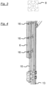
- the ceiling elements 6 essentially consist of a T-slot aluminum profile with a Figure 3 shown square cross section 8 of 40 x 40 mm.
- the shuttle warehouse 1 On both sides of a horizontally running lane 9, the shuttle warehouse 1 has two rows 10 with a total of eighty storage locations 11 for (exemplarily only in Figure 8 shown) transport boxes 12.
- the transport boxes 12 are standardized open containers for up to 25 wafer slices with a diameter of 200 mm.
- Each of the ceiling elements 6 has two support elements 13 on either side of the aisle 9, which are connected in a U-shape transverse to the aisle 9 to a stabilizing element 14. After being fastened to the ceiling by means of a threaded rod 15 on the ceiling elements 6, the support elements 13 are leveled vertically within an adjustment range of 10 cm to the height of a storage plane (not shown) using laser systems (level and line) to compensate for any unevenness in the ceiling and are fixed in the selected position using three clamping screws 16.
- Shuttle Warehouse 1 was constructed from five standardized modules, namely a start module 17, two triple modules 18, a transfer module 19, two single modules 20, and an end module.
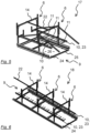
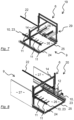
- the start module 17, the triple module 18, the transfer module 19, and the single module 20 are shown in the Figures 5 to 8 shown in isolation.
- the modules for the project planning each include the corresponding ceiling elements 6, holders 22 for the power supply between the Ceiling elements 6 in the longitudinal direction of the aisle 9, one or more storage groups 23, a floor group 24 with a frame 25 made of the above-mentioned aluminum profile and a grid-shaped floor element 26 inserted therein and (for simplification only in Figure 8 shown) side walls 27.
- the end module 21 is a mirror image of the start module 17, but includes two additional side walls 27 and an additional receptacle 22 for the power supply along the lane 9.
- the single module 20 and the transfer module 19 have a single grid dimension of 7 along the lane 9, the triple module 18 has a triple grid dimension of 7, the start module 17 and the end module 21 have a one and a half times grid dimension of 7.
- the transfer module 19 has a storage group 23 and opposite this an opening 28 for the Figure 7 indicated transfer station 29. All other modules each have two storage groups 23 arranged opposite each other along the aisle 9. Each storage group 23 has four storage locations per grid dimension 7.
- the mounts 22 for the power supply along the aisle 9 then the pre-assembled storage groups 23 and floor groups 24 and the side walls 27 are attached to the holding elements 13 and finally a linear motor (not shown) for the storage vehicle along the aisle 9 on the floor groups 24 and a lifting station (not shown) with the transfer station 29 is provided on the transfer module 19.
- the storage vehicle is inductively supplied with energy via a current collector from the power supply receptacles 22.
Landscapes
- Engineering & Computer Science (AREA)
- Architecture (AREA)
- Mechanical Engineering (AREA)
- Physics & Mathematics (AREA)
- Electromagnetism (AREA)
- Civil Engineering (AREA)
- Structural Engineering (AREA)
- Warehouses Or Storage Devices (AREA)
- Container, Conveyance, Adherence, Positioning, Of Wafer (AREA)
Description
- Die Erfindung betrifft zunächst ein Shuttlelager für Transportboxen für Waferscheiben mit einer horizontal verlaufenden Gasse für ein Lagerfahrzeug, mit einem Linearmotor für das Lagerfahrzeug auf einem Boden der Gasse, mit einer Übergabestation zur Übergabe der Transportboxen in das oder aus dem Shuttlelager, mit einer Haltekonstruktion, die von einer Raumdecke abgehängt ist und mit Lagerplätzen für die Transportboxen, die in einer horizontal verlaufenden Lagerebene entlang der Gasse an der Haltekonstruktion befestigt sind. Die Erfindung betrifft weiter ein Verfahren zum Herstellen eines solchen Shuttlelagers. Solche Shuttlelager, wie sie beispielsweise aus
WO 03/046954 A2 - Weiterer Stand der Technik wird in den Dokumenten
DE 10 2008 015 472 A1 ,DE 20 2012 000 143 U1 undKR 10-2021-0143566 - Um die Beschädigung der empfindlichen Waferscheiben bei Lagerung und Handhabung zu vermeiden, müssen Lagerplätze und Transportwege exakt zueinander ausgerichtet werden. Der Aufbau des bekannten Shuttlelagers ausgehend von einer typischerweise mit deutlich höheren Toleranzen hergestellten Raumdecke stellt daher hohe Anforderungen an Material, Abläufe und die Fähigkeiten der ausführenden Personen.
- Der Erfindung liegt die Aufgabe zugrunde, die Herstellung des Shuttlelagers zu vereinfachen.
- Ausgehend von dem bekannten Shuttlelager wird nach der Erfindung vorgeschlagen, an der Raumdecke befestigte Deckenelemente, und an den Deckenelementen angebrachte Halteelemente für die Lagerplätze vorzusehen, wobei zum Herstellen des Shuttlelagers zunächst die Deckenelemente an der Raumdecke befestigt und die Halteelemente für die Lagerplätze in einer vertikalen Höhe in der Lagerebene nivelliert und dann die Lagerplätze an den Halteelementen befestigt werden.
- In einem "Shuttlelager" wird das Lagergut horizontal in der Gasse durch ein autonomes Lagerfahrzeug - den "Shuttle" - und senkrecht zu der Lagerebene davon getrennt durch eine Hubstation oder einen Aufzug außerhalb der Gasse gefördert. Als Transportboxen kommen in einem erfindungsgemäßen Shuttlelager insbesondere als Carrier, HA200, SMIF oder FOUP bezeichnete Standardbehälter in Betracht.
- Die Montage der Haltekonstruktion an der Raumdecke ist durch die nivellierbaren Halteelemente von der Ausrichtung und Montage der Lagerplätze und Transportwege konstruktiv getrennt. Das erfindungsgemäße Shuttlelager erleichtert und beschleunigt gleichermaßen Beschaffung, Bevorratung, Planung und Montage.
- Vorzugsweise sind in einem erfindungsgemäßen Shuttlelager die Halteelemente in Längsrichtung der Gasse in einem Rastermaß beabstandet. Die Rasterung erlaubt eine Standardisierung der Planung und Herstellung des Shuttlelagers.
- Vorzugsweise sind die Lagerplätze eines solchen erfindungsgemäßen Shuttlelagers in Lagergruppen vormontiert, die in einer Längsrichtung der Gasse ein Rastermaß oder ein Vielfaches, vorzugsweise ein zwei- oder dreifaches des Rastermaßes aufweisen. Weiter vorzugsweise weisen Bodengruppen, die das Shuttlelager unten abschließen, ein entsprechendes Maß auf.
- Vormontierte Baugruppen beschleunigen die Montage des erfindungsgemäßen Shuttlelagers und reduzieren so insbesondere die Stillstandszeiten von bestehenden Fertigungsumgebungen unterhalb der Lagerebene. Darüber hinaus ist die Lagerhaltung durch die reduzierte Anzahl unterschiedlicher Komponenten für die Herstellung des Shuttlelagers vereinfacht.
- Weiter vorzugsweise weist ein solches erfindungsgemäßes Shuttlelager Start- und Endmodule mit einer einseitigen Begrenzung der Gasse und ein Übergabemodul mit der Übergabestation auf. Diese Modularisierung vereinfacht die Planung des erfindungsgemäßen Shuttlelagers.
- Die Verwendung von Modulen und Baugruppen in einem einheitlichen Rastermaß erhöht einerseits die Flexibilität in der Anpassung des erfindungsgemäßen Shuttlelagers an unterschiedliche räumliche Anforderungen und vermindert zudem wiederum die Anzahl unterschiedlicher Komponenten und damit den Aufwand der Lagerhaltung.
- Vorzugsweise weisen die Deckenelemente eines solchen erfindungsgemäßen Shuttlelagers je zwei an der Gasse einander gegenüber angeordnete Halteelemente und vorzugsweise ein horizontal verlaufendes Stabilisierungselement zwischen den Halteelementen 13 auf. Die Befestigung zwischen einander gegenüber angeordneten Halteelementen 13 vermeidet ein Verkippen von Lagerplätzen und Transportweg quer zu der Gasse. Das Stabilisierungselement vereinfacht die Montage der einander gegenüber angeordneten Halteelemente an der Raumdecke im gewünschten Abstand.
- Vorzugsweise weist ein erfindungsgemäßes Shuttlelager einen Linearmotor für das Lagerfahrzeug auf. Weiter vorzugsweise befindet sich der Linearmotor auf dem Boden der Gasse. Das Lagerfahrzeug wird weiter vorzugsweise induktiv mit Energie versorgt. Gegenüber alternativ möglichen Antrieben durch Riemenachsen oder Zahnstangen sowie der alternativ möglichen Energieversorgung über Kabel und Kabelketten oder Schleifkontakte vermeidet ein solches erfindungsgemäßes Shuttlelager insbesondere unter Reinraumbedingungen Abrieb und Partikelemission auf die Wafer.
- Vorzugsweise weist ein erfindungsgemäßes Shuttlelager einen gitterförmig ausgebildeten Boden der Gasse auf. Weiter vorzugsweise weist ein solches erfindungsgemäßes Shuttlelager parallel zu der Gasse angeordnete Außenwände auf. Beides vermeidet Eingriffe von Außen in die Lagerplätze und Transportwege des Shuttlelagers und ermöglicht dennoch eine laminare vertikale Durchströmung von Lagerplätzen und Transportweg von oben nach unten, um eine Kontamination der Waferscheiben zu vermeiden.
- Vorzugsweise sind in einem erfindungsgemäßen Shuttlelager die Lagerplätze in zwei Reihen beidseits der Gasse angeordnet. Die Kapazität des erfindungsgemäßen Shuttlelagers wird so verdoppelt.
- Ein erfindungsgemäßes Shuttlelager kann mehrere Übergabestationen aufweisen, mehrere erfindungsgemäße Shuttlelager über- und/oder nebeneinander können zu einer Lagereinrichtung kombiniert werden.
- Ausgehend von dem bekannten Verfahren wird erfindungsgemäß vorgeschlagen, dass an der Raumdecke eine Haltekonstruktion befestigt wird und in einer horizontal verlaufenden Lagerebene in die Haltekonstruktion vormontierte Module eingehängt werden, die das Shuttlelager bilden. Das erfindungsgemäße Verfahren erlaubt die Herstellung eines erfindungsgemäßen Shuttlelagers und zeichnet sich gleichermaßen durch dessen vorstehend beschriebene Vorteile aus.
- Vorzugsweise werden im Rahmen eines erfindungsgemäßen Verfahrens nach Befestigen der Haltekonstruktion an der Raumdecke Halteelemente der Haltekonstruktion in einer vertikalen Höhe in die Lagerebene nivelliert. Nach Befestigen der Haltekonstruktion an der Raumdecke können die Halteelemente besonders einfach mit Hilfe eines Nivellierlasergeräts nivelliert werden. Wenn die Module erst anschließend montiert werden, stören sie das Nivellieren nicht.
- Das erfindungsgemäße Shuttlelager ermöglicht eine Gasse mit einem einzelnen Lagerfahrzeug bis zu einer Länge von 48 m.
- Die Erfindung wird nachfolgend anhand eines Ausführungsbeispiels erläutert. Es zeigen
- Fig. 1
- ein erfindungsgemäßes Shuttlelager,
- Fig. 2
- ein Deckenelement des Shuttlelagers,
- Fig. 3
- einen Profilquerschnitt und
- Fig. 4
- ein Detail des Deckenelements,
- Fig. 5
- ein Endmodul des Shuttlelagers,
- Fig. 6
- ein dreifaches Modul des Shuttlelagers,
- Fig. 7
- ein Übergabemodul des Shuttlelagers und
- Fig. 8
- ein einfaches Modul des Shuttlelagers.
- Das in
Figur 1 gezeigte erfindungsgemäße Shuttlelager 1 weist eine Breite 2 von 124 cm, eine Länge 3 von 1446 cm, und eine Höhe 4 von 90 cm auf und befindet sich in einem nicht dargestellten Reinraum zur Halbleiterverarbeitung unter einer unebenen Raumdecke. - Zur Herstellung des Shuttlelagers 1 wird zunächst eine Haltekonstruktion 5 mit in
Figur 2 gezeigten Deckenelementen 6 im Abstand eines Rastermaßes 7 von 120 cm an der Raumdecke befestigt. Die Deckenelemente 6 bestehen im Wesentlichen aus einem T-Nut-Aluminiumprofil mit einem inFigur 3 gezeigten quadratischen Querschnitt 8 von 40 x 40 mm. - Beidseits einer horizontal verlaufenden Gasse 9 weist das Shuttlelager 1 zwei Reihen 10 mit zusammen achtzig Lagerplätzen 11 für (beispielhaft erst in
Figur 8 dargestellte) Transportboxen 12 auf. Die Transportboxen 12 sind standardisierte offene Behälter für bis zu 25 Waferscheiben mit einem Durchmesser von 200 mm auf. - Jedes der Deckenelemente 6 weist jeweils beidseits der Gasse 9 zwei Halteelemente 13 auf, die U-förmig quer zu der Gasse 9 mit einem Stabilisierungselement 14 verbunden sind. Die Halteelemente 13 werden nach Befestigung an der Raumdecke mittels eines Gewindestabs 15 an den Deckenelementen 6 in einem Verstellbereich von 10 cm vertikal auf Höhe einer nicht dargestellten Lagerebene mittels Lasersystemen (Waage und Linie) nivelliert, um die Unebenheiten der Raumdecke auszugleichen und in der jeweils gewählten Position mittels drei Klemmschrauben 16 fixiert.
- In der Projektierung wurde das Shuttlelager 1 aus fünf standardisierten Modulen aufgebaut, nämlich einem Startmodul 17, zwei Dreifachmodulen 18, einem Übergabemodul 19, zwei Einfachmodulen 20 und einem Endmodul. Das Startmodul 17, das Dreifachmodul 18, das Übergabemodul 19 und das Einfachmodul 20 sind in den
Figuren 5 bis 8 isoliert dargestellt. - Die Module für die Projektierung umfassen jeweils die zugehörigen Deckenelemente 6, Aufnahmen 22 für die Spannungsversorgung zwischen den Deckenelementen 6 in Längsrichtung der Gasse 9, eine oder mehrere Lagergruppen 23, eine Bodengruppe 24 mit einem Rahmen 25 aus dem genannten Aluminiumprofil und einem darin eingelegten gitterförmig ausgebildeten Bodenelement 26 und (vereinfachend nur in
Figur 8 dargestellte) Seitenwände 27 auf. Das Endmodul 21 entspricht spiegelbildlich dem Startmodul 17, umfasst aber abweichend zwei zusätzliche Seitenwände 27 und eine zusätzliche Aufnahme 22 für die Spannungsversorgung entlang der Gasse 9. - Das Einfachmodul 20 und das Übergabemodul 19 weist entlang der Gasse 9 das einfache Rastermaß 7, das Dreifachmodul 18 das dreifache Rastermaß 7, das Startmodul 17 und das Endmodul 21 weist das eineinhalbfache Rastermaß 7 auf. Das Übergabemodul 19 weist eine Lagergruppe 23 und dieser gegenüber eine Öffnung 28 für die in
Figur 7 angedeutete Übergabestation 29 auf. Alle anderen Module weisen je zwei entlang der Gasse 9 einander gegenüber angeordnete Lagergruppen 23 auf. Jede Lagergruppe 23 weist je Rastermaß 7 vier Lagerplätze auf. - Zur Montage des Shuttlelagers 1 werden nach der Nivellierung zunächst die Aufnahmen 22 für die Spannungsversorgung entlang der Gasse 9, dann die vormontierten Lagergruppen 23 und Bodengruppen 24 und die Seitenwände 27 an den Halteelementen 13 und zuletzt ein nicht dargestellter Linearmotor für das Lagerfahrzeug entlang der Gasse 9 auf den Bodengruppen 24 angebracht und am Übergabemodul 19 eine nicht dargestellte Hubstation mit der Übergabestation 29 bereitgestellt.
- Das nicht dargestellte Lagerfahrzeug wird über einen Stromabnehmer aus den Aufnahmen 22 für die Spannungsversorgung induktiv mit Energie versorgt.
- Der Schutzbereich des europäischen Patents wird durch die Patentansprüche bestimmt.
- In den Figuren sind
- 1
- Shuttlelager
- 2
- Breite
- 3
- Länge
- 4
- Höhe
- 5
- Haltekonstruktion
- 6
- Deckenelement
- 7
- Rastermaß
- 8
- Querschnitt
- 9
- Gasse
- 10
- Reihe
- 11
- Lagerplatz
- 12
- Transportbox
- 13
- Halteelement
- 14
- Stabilisierungselement
- 15
- Gewindestab
- 16
- Klemmschraube
- 17
- Startmodul
- 18
- Dreifachmodul
- 19
- Übergabemodul
- 20
- Einfachmodul
- 21
- Endmodul
- 22
- Aufnahme für die Spannungsversorgung
- 23
- Lagergruppe
- 24
- Bodengruppe
- 25
- Rahmen
- 26
- Bodenelement
- 27
- Seitenwand
- 28
- Öffnung
- 29
- Übergabestation
Claims (8)
- Shuttlelager (1) für Transportboxen (12) für Waferscheiben• mit einer horizontal verlaufenden Gasse (9) für ein Lagerfahrzeug,• mit einem Linearmotor für das Lagerfahrzeug auf einem Boden der Gasse (9),• mit einer Übergabestation (29) zur Übergabe der Transportboxen (12) in das oder aus dem Shuttlelager (1),• mit einer Haltekonstruktion (5), die von einer Raumdecke abgehängt ist und• mit Lagerplätzen (11) für die Transportboxen (12), die in einer horizontal verlaufenden Lagerebene entlang der Gasse (9) an der Haltekonstruktion (5) befestigt sind,und mit an der Raumdecke befestigten Deckenelementen (6), und an den Deckenelementen (6) in einer vertikalen Höhe nivellierbar angebrachte Halteelemente (13) für die Lagerplätze (11), wobei zum Herstellen des Shuttlelagers (1) zunächst die Deckenelemente (6) an der Raumdecke befestigt und die Halteelemente (13) für die Lagerplätze in einer vertikalen Höhe in der Lagerebene nivelliert und dann die Lagerplätze an den Halteelementen (13) befestigt werden.
- Shuttlelager (1) nach dem vorgenannten Anspruch, dadurch gekennzeichnet, dass die Halteelemente (13) in Längsrichtung der Gasse (9) in einem Rastermaß (7) beabstandet sind.
- Shuttlelager (1) nach dem vorgenannten Anspruch, gekennzeichnet durch vormontierte Lagergruppen (23) mit den Lagerplätzen (11) und/oder das Shuttlelager (1) unten abschließenden Bodengruppen (24), die in der Längsrichtung das Rastermaß (7) oder ein Vielfaches, vorzugsweise ein zwei- oder dreifaches des Rastermaßes (7) aufweisen.
- Shuttlelager (1) nach einem der Ansprüche 2 oder 3, gekennzeichnet durch ein Startmodul (17) und ein Endmodul (21) mit einer einseitigen Begrenzung der Gasse (9) und mindestens ein Übergabemodul (19) mit der Übergabestation (29).
- Shuttlelager (1) nach einem der vorgenannten Ansprüche, dadurch gekennzeichnet, dass die Deckenelemente (6) je zwei an der Gasse (9) einander gegenüber angeordnete Halteelemente (13) und vorzugsweise ein horizontal verlaufendes Stabilisierungselement (14) zwischen den Halteelementen (13) aufweisen.
- Shuttlelager (1) nach einem der vorgenannten Ansprüche, gekennzeichnet durch einen gitterförmig ausgebildeten Boden der Gasse (9) und vorzugsweise parallel zu der Gasse (9) angeordnete Außenwände.
- Shuttlelager (1) nach einem der vorgenannten Ansprüche, dadurch gekennzeichnet, dass die Lagerplätze in zwei Reihen (10) beidseits der Gasse (9) angeordnet sind.
- Verfahren zum Herstellen eines Shuttlelagers (1) für Transportboxen (12) für Waferscheiben mit einer horizontal verlaufenden Gasse (9) für ein Lagerfahrzeug, mit einem Linearmotor für das Lagerfahrzeug auf einem Boden der Gasse (9), mit einer Übergabestation (29) zur Übergabe der Transportboxen (12) in das oder aus dem Shuttlelager (1), mit einer Haltekonstruktion (5), die von einer Raumdecke abgehängt ist und mit Lagerplätzen (11) für die Transportboxen (12) in einer horizontal verlaufenden Lagerebene entlang der Gasse (9) an der Haltekonstruktion (5), dadurch gekennzeichnet, dass zunächst Deckenelemente (6) an der Raumdecke befestigt und Halteelemente (13) für die Lagerplätze in einer vertikalen Höhe in der Lagerebene nivelliert und dann die Lagerplätze an den Halteelementen (13) befestigt werden.
Priority Applications (3)
| Application Number | Priority Date | Filing Date | Title |
|---|---|---|---|
| EP23158267.7A EP4432336B1 (de) | 2023-02-23 | 2023-02-23 | Shuttlelager und verfahren zum herstellen desselben |
| JP2024025398A JP2024120175A (ja) | 2023-02-23 | 2024-02-22 | シャトル式ストッカ、およびシャトル式ストッカを製造する方法 |
| US18/585,591 US20240327119A1 (en) | 2023-02-23 | 2024-02-23 | Shuttle storage and method for producing the same |
Applications Claiming Priority (1)
| Application Number | Priority Date | Filing Date | Title |
|---|---|---|---|
| EP23158267.7A EP4432336B1 (de) | 2023-02-23 | 2023-02-23 | Shuttlelager und verfahren zum herstellen desselben |
Publications (3)
| Publication Number | Publication Date |
|---|---|
| EP4432336A1 EP4432336A1 (de) | 2024-09-18 |
| EP4432336B1 true EP4432336B1 (de) | 2025-06-18 |
| EP4432336C0 EP4432336C0 (de) | 2025-06-18 |
Family
ID=85381014
Family Applications (1)
| Application Number | Title | Priority Date | Filing Date |
|---|---|---|---|
| EP23158267.7A Active EP4432336B1 (de) | 2023-02-23 | 2023-02-23 | Shuttlelager und verfahren zum herstellen desselben |
Country Status (3)
| Country | Link |
|---|---|
| US (1) | US20240327119A1 (de) |
| EP (1) | EP4432336B1 (de) |
| JP (1) | JP2024120175A (de) |
Family Cites Families (10)
| Publication number | Priority date | Publication date | Assignee | Title |
|---|---|---|---|---|
| DE10157192A1 (de) | 2001-11-23 | 2003-06-12 | Ortner C L S Gmbh | Lagereinrichtung |
| US10957569B2 (en) * | 2002-10-11 | 2021-03-23 | Murata Machinery Ltd. | Access to one or more levels of material storage shelves by an overhead hoist transport vehicle from a single track position |
| DE102008015472A1 (de) * | 2008-03-12 | 2009-09-17 | HAP Handhabungs-, Automatisierungs- und Präzisionstechnik GmbH | Tragelement zur deckenhängenden Lagerung von Behältnissen oder Gegenständen |
| DE202012000143U1 (de) * | 2012-01-03 | 2012-02-08 | HAP Handhabungs-, Automatisierungs- und Präzisionstechnik GmbH | System zur Zwischenlagerung von Behältnissen |
| KR101915982B1 (ko) * | 2018-07-25 | 2018-11-07 | (주)삼우종합건축사사무소 | 가변높이 구조를 가진 크린룸용 조립식 시스템 천장 |
| CN112930312B (zh) * | 2018-11-06 | 2022-08-30 | 村田机械株式会社 | 桥式输送车 |
| KR102449019B1 (ko) * | 2020-04-29 | 2022-09-29 | 삼성전자(주) | 보강 용이성과 수평조정 및 가변높이 구조를 갖는 크린룸용 조립식 시스템 천장 |
| KR102387045B1 (ko) * | 2020-04-29 | 2022-04-15 | 삼성전자(주) | 2단 가변높이 구조를 가진 크린룸용 조립식 시스템 천장 |
| KR102861961B1 (ko) * | 2020-05-20 | 2025-09-18 | 세메스 주식회사 | 물품 반송 시스템 및 물품 저장 장치 |
| TWI838607B (zh) * | 2021-02-03 | 2024-04-11 | 艾迪森科技有限公司 | 半導體晶圓盒倉儲運輸結構系統 |
-
2023
- 2023-02-23 EP EP23158267.7A patent/EP4432336B1/de active Active
-
2024
- 2024-02-22 JP JP2024025398A patent/JP2024120175A/ja active Pending
- 2024-02-23 US US18/585,591 patent/US20240327119A1/en active Pending
Also Published As
| Publication number | Publication date |
|---|---|
| EP4432336A1 (de) | 2024-09-18 |
| US20240327119A1 (en) | 2024-10-03 |
| JP2024120175A (ja) | 2024-09-04 |
| EP4432336C0 (de) | 2025-06-18 |
Similar Documents
| Publication | Publication Date | Title |
|---|---|---|
| DE202020100289U1 (de) | Automatisches dreidimensionales Lagersystem | |
| EP3419918B1 (de) | Regalbediengerät für einen parallelen betrieb eines hochregallagers sowie ein betriebsverfahren hierfür | |
| EP4328154B1 (de) | Lagersystem zum lagern von behältern | |
| DE19900804C2 (de) | Fördersystem | |
| DE112014001586B4 (de) | Vorrichtung zur Bearbeitung von zwei oder mehreren Substraten in einem Batch-Prozess | |
| DE102011012424A1 (de) | Lager- und Kommissioniersystem mit Shuttle | |
| EP4219347B1 (de) | Lagersystem zum lagern von behältern | |
| DE102019201797A1 (de) | Wendestand | |
| DE102020205747A1 (de) | Verfahren zum Lagern und/oder Entnehmen eines Lagerguts in oder aus einem Lagersystem sowie Lagersystem | |
| EP4432336A1 (de) | Shuttlelager und verfahren zum herstellen desselben | |
| DE102017222317B4 (de) | Automatisiertes Regallager, Tragwerkstruktur zum Einbau in ein Regallager sowie Verfahren zur Umrüstung eines Regallagers | |
| DE102018124599A1 (de) | Baukasten zur Herstellung einer Fördereinrichtung umfassend eine Mehrzahl von Förderzonen | |
| DE10147360A1 (de) | Verpackungsmaschine mit schmalem Säulenverbinder | |
| WO1999010258A1 (de) | Dynamisches kompaktlager | |
| DE102019109841A1 (de) | Regalbediengerät, Regallager, und Anordnung umfassend eine Arbeitsstation und ein dazu benachbartes Lager | |
| DE102019121346A1 (de) | Deckenmodul zum Aufbau eines Reinraums | |
| DE202019101515U1 (de) | Anordnung umfassend eine Arbeitsstation und ein dazu benachbartes Lager zum Lagern von in der Arbeitsstation benötigten Gegenständen | |
| DE102012112828A1 (de) | Lager und Lagerbediengeräte mit Passierfunktion | |
| DE60201531T2 (de) | Verfahren zur herstellung von behältergestellen | |
| DE102019133074A1 (de) | Lagersystem | |
| DE102021126500B3 (de) | Regallagersystem mit einem dreidimensionalen Regallager und mindestens einem Fahrzeug zur Einlagerung und Auslagerung von Ladungsträgern | |
| DE102008015472A1 (de) | Tragelement zur deckenhängenden Lagerung von Behältnissen oder Gegenständen | |
| DE3412526A1 (de) | Einrichtung mit mehreren bearbeitungs- und/oder montagemaschinen | |
| EP4192765A1 (de) | Lageranordnung zum lagern von ladungsträgern und technische anlage | |
| EP3110724B1 (de) | Lagergebäude |
Legal Events
| Date | Code | Title | Description |
|---|---|---|---|
| STAA | Information on the status of an ep patent application or granted ep patent |
Free format text: STATUS: EXAMINATION IS IN PROGRESS |
|
| PUAI | Public reference made under article 153(3) epc to a published international application that has entered the european phase |
Free format text: ORIGINAL CODE: 0009012 |
|
| 17P | Request for examination filed |
Effective date: 20230816 |
|
| AK | Designated contracting states |
Kind code of ref document: A1 Designated state(s): AL AT BE BG CH CY CZ DE DK EE ES FI FR GB GR HR HU IE IS IT LI LT LU LV MC ME MK MT NL NO PL PT RO RS SE SI SK SM TR |
|
| GRAP | Despatch of communication of intention to grant a patent |
Free format text: ORIGINAL CODE: EPIDOSNIGR1 |
|
| STAA | Information on the status of an ep patent application or granted ep patent |
Free format text: STATUS: GRANT OF PATENT IS INTENDED |
|
| INTG | Intention to grant announced |
Effective date: 20250324 |
|
| GRAS | Grant fee paid |
Free format text: ORIGINAL CODE: EPIDOSNIGR3 |
|
| GRAA | (expected) grant |
Free format text: ORIGINAL CODE: 0009210 |
|
| STAA | Information on the status of an ep patent application or granted ep patent |
Free format text: STATUS: THE PATENT HAS BEEN GRANTED |
|
| AK | Designated contracting states |
Kind code of ref document: B1 Designated state(s): AL AT BE BG CH CY CZ DE DK EE ES FI FR GB GR HR HU IE IS IT LI LT LU LV MC ME MK MT NL NO PL PT RO RS SE SI SK SM TR |
|
| REG | Reference to a national code |
Ref country code: GB Ref legal event code: FG4D Free format text: NOT ENGLISH |
|
| REG | Reference to a national code |
Ref country code: CH Ref legal event code: EP |
|
| REG | Reference to a national code |
Ref country code: DE Ref legal event code: R096 Ref document number: 502023001164 Country of ref document: DE |
|
| REG | Reference to a national code |
Ref country code: CH Ref legal event code: EP |
|
| REG | Reference to a national code |
Ref country code: IE Ref legal event code: FG4D Free format text: LANGUAGE OF EP DOCUMENT: GERMAN |
|
| U01 | Request for unitary effect filed |
Effective date: 20250717 |
|
| U07 | Unitary effect registered |
Designated state(s): AT BE BG DE DK EE FI FR IT LT LU LV MT NL PT RO SE SI Effective date: 20250723 |
|
| PG25 | Lapsed in a contracting state [announced via postgrant information from national office to epo] |
Ref country code: NO Free format text: LAPSE BECAUSE OF FAILURE TO SUBMIT A TRANSLATION OF THE DESCRIPTION OR TO PAY THE FEE WITHIN THE PRESCRIBED TIME-LIMIT Effective date: 20250918 Ref country code: GR Free format text: LAPSE BECAUSE OF FAILURE TO SUBMIT A TRANSLATION OF THE DESCRIPTION OR TO PAY THE FEE WITHIN THE PRESCRIBED TIME-LIMIT Effective date: 20250919 |
|
| PG25 | Lapsed in a contracting state [announced via postgrant information from national office to epo] |
Ref country code: HR Free format text: LAPSE BECAUSE OF FAILURE TO SUBMIT A TRANSLATION OF THE DESCRIPTION OR TO PAY THE FEE WITHIN THE PRESCRIBED TIME-LIMIT Effective date: 20250618 |
|
| PG25 | Lapsed in a contracting state [announced via postgrant information from national office to epo] |
Ref country code: RS Free format text: LAPSE BECAUSE OF FAILURE TO SUBMIT A TRANSLATION OF THE DESCRIPTION OR TO PAY THE FEE WITHIN THE PRESCRIBED TIME-LIMIT Effective date: 20250918 |
|
| PG25 | Lapsed in a contracting state [announced via postgrant information from national office to epo] |
Ref country code: IS Free format text: LAPSE BECAUSE OF FAILURE TO SUBMIT A TRANSLATION OF THE DESCRIPTION OR TO PAY THE FEE WITHIN THE PRESCRIBED TIME-LIMIT Effective date: 20251018 |
|
| PG25 | Lapsed in a contracting state [announced via postgrant information from national office to epo] |
Ref country code: SM Free format text: LAPSE BECAUSE OF FAILURE TO SUBMIT A TRANSLATION OF THE DESCRIPTION OR TO PAY THE FEE WITHIN THE PRESCRIBED TIME-LIMIT Effective date: 20250618 |
|
| U20 | Renewal fee for the european patent with unitary effect paid |
Year of fee payment: 4 Effective date: 20251208 |
|
| PG25 | Lapsed in a contracting state [announced via postgrant information from national office to epo] |
Ref country code: CZ Free format text: LAPSE BECAUSE OF FAILURE TO SUBMIT A TRANSLATION OF THE DESCRIPTION OR TO PAY THE FEE WITHIN THE PRESCRIBED TIME-LIMIT Effective date: 20250618 |
|
| PG25 | Lapsed in a contracting state [announced via postgrant information from national office to epo] |
Ref country code: PL Free format text: LAPSE BECAUSE OF FAILURE TO SUBMIT A TRANSLATION OF THE DESCRIPTION OR TO PAY THE FEE WITHIN THE PRESCRIBED TIME-LIMIT Effective date: 20250618 |
|
| PG25 | Lapsed in a contracting state [announced via postgrant information from national office to epo] |
Ref country code: SK Free format text: LAPSE BECAUSE OF FAILURE TO SUBMIT A TRANSLATION OF THE DESCRIPTION OR TO PAY THE FEE WITHIN THE PRESCRIBED TIME-LIMIT Effective date: 20250618 |
|
| PG25 | Lapsed in a contracting state [announced via postgrant information from national office to epo] |
Ref country code: ES Free format text: LAPSE BECAUSE OF FAILURE TO SUBMIT A TRANSLATION OF THE DESCRIPTION OR TO PAY THE FEE WITHIN THE PRESCRIBED TIME-LIMIT Effective date: 20250618 |
|
| PLBE | No opposition filed within time limit |
Free format text: ORIGINAL CODE: 0009261 |
|
| STAA | Information on the status of an ep patent application or granted ep patent |
Free format text: STATUS: NO OPPOSITION FILED WITHIN TIME LIMIT |
|
| REG | Reference to a national code |
Ref country code: CH Ref legal event code: L10 Free format text: ST27 STATUS EVENT CODE: U-0-0-L10-L00 (AS PROVIDED BY THE NATIONAL OFFICE) Effective date: 20260430 |