EP4431316A1 - Layout structure of swing arm assembly - Google Patents
Layout structure of swing arm assembly Download PDFInfo
- Publication number
- EP4431316A1 EP4431316A1 EP23191322.9A EP23191322A EP4431316A1 EP 4431316 A1 EP4431316 A1 EP 4431316A1 EP 23191322 A EP23191322 A EP 23191322A EP 4431316 A1 EP4431316 A1 EP 4431316A1
- Authority
- EP
- European Patent Office
- Prior art keywords
- swing arm
- connection
- hub motor
- vehicle
- steering knuckle
- Prior art date
- Legal status (The legal status is an assumption and is not a legal conclusion. Google has not performed a legal analysis and makes no representation as to the accuracy of the status listed.)
- Pending
Links
Images


Classifications
-
- B—PERFORMING OPERATIONS; TRANSPORTING
- B62—LAND VEHICLES FOR TRAVELLING OTHERWISE THAN ON RAILS
- B62D—MOTOR VEHICLES; TRAILERS
- B62D7/00—Steering linkage; Stub axles or their mountings
- B62D7/16—Arrangement of linkage connections
-
- B—PERFORMING OPERATIONS; TRANSPORTING
- B60—VEHICLES IN GENERAL
- B60G—VEHICLE SUSPENSION ARRANGEMENTS
- B60G3/00—Resilient suspensions for a single wheel
- B60G3/18—Resilient suspensions for a single wheel with two or more pivoted arms, e.g. parallelogram
- B60G3/20—Resilient suspensions for a single wheel with two or more pivoted arms, e.g. parallelogram all arms being rigid
-
- B—PERFORMING OPERATIONS; TRANSPORTING
- B60—VEHICLES IN GENERAL
- B60G—VEHICLE SUSPENSION ARRANGEMENTS
- B60G7/00—Pivoted suspension arms; Accessories thereof
- B60G7/001—Suspension arms, e.g. constructional features
-
- B—PERFORMING OPERATIONS; TRANSPORTING
- B60—VEHICLES IN GENERAL
- B60G—VEHICLE SUSPENSION ARRANGEMENTS
- B60G7/00—Pivoted suspension arms; Accessories thereof
- B60G7/005—Ball joints
-
- B—PERFORMING OPERATIONS; TRANSPORTING
- B60—VEHICLES IN GENERAL
- B60G—VEHICLE SUSPENSION ARRANGEMENTS
- B60G7/00—Pivoted suspension arms; Accessories thereof
- B60G7/006—Attaching arms to sprung or unsprung part of vehicle, characterised by comprising attachment means controlled by an external actuator, e.g. a fluid or electrical motor
-
- B—PERFORMING OPERATIONS; TRANSPORTING
- B60—VEHICLES IN GENERAL
- B60G—VEHICLE SUSPENSION ARRANGEMENTS
- B60G7/00—Pivoted suspension arms; Accessories thereof
- B60G7/008—Attaching arms to unsprung part of vehicle
-
- B—PERFORMING OPERATIONS; TRANSPORTING
- B60—VEHICLES IN GENERAL
- B60K—ARRANGEMENT OR MOUNTING OF PROPULSION UNITS OR OF TRANSMISSIONS IN VEHICLES; ARRANGEMENT OR MOUNTING OF PLURAL DIVERSE PRIME-MOVERS IN VEHICLES; AUXILIARY DRIVES FOR VEHICLES; INSTRUMENTATION OR DASHBOARDS FOR VEHICLES; ARRANGEMENTS IN CONNECTION WITH COOLING, AIR INTAKE, GAS EXHAUST OR FUEL SUPPLY OF PROPULSION UNITS IN VEHICLES
- B60K7/00—Disposition of motor in, or adjacent to, traction wheel
-
- B—PERFORMING OPERATIONS; TRANSPORTING
- B60—VEHICLES IN GENERAL
- B60K—ARRANGEMENT OR MOUNTING OF PROPULSION UNITS OR OF TRANSMISSIONS IN VEHICLES; ARRANGEMENT OR MOUNTING OF PLURAL DIVERSE PRIME-MOVERS IN VEHICLES; AUXILIARY DRIVES FOR VEHICLES; INSTRUMENTATION OR DASHBOARDS FOR VEHICLES; ARRANGEMENTS IN CONNECTION WITH COOLING, AIR INTAKE, GAS EXHAUST OR FUEL SUPPLY OF PROPULSION UNITS IN VEHICLES
- B60K7/00—Disposition of motor in, or adjacent to, traction wheel
- B60K7/0007—Disposition of motor in, or adjacent to, traction wheel the motor being electric
-
- B—PERFORMING OPERATIONS; TRANSPORTING
- B62—LAND VEHICLES FOR TRAVELLING OTHERWISE THAN ON RAILS
- B62D—MOTOR VEHICLES; TRAILERS
- B62D7/00—Steering linkage; Stub axles or their mountings
- B62D7/18—Steering knuckles; King pins
-
- B—PERFORMING OPERATIONS; TRANSPORTING
- B60—VEHICLES IN GENERAL
- B60G—VEHICLE SUSPENSION ARRANGEMENTS
- B60G2200/00—Indexing codes relating to suspension types
- B60G2200/10—Independent suspensions
- B60G2200/14—Independent suspensions with lateral arms
- B60G2200/144—Independent suspensions with lateral arms with two lateral arms forming a parallelogram
-
- B—PERFORMING OPERATIONS; TRANSPORTING
- B60—VEHICLES IN GENERAL
- B60G—VEHICLE SUSPENSION ARRANGEMENTS
- B60G2200/00—Indexing codes relating to suspension types
- B60G2200/40—Indexing codes relating to the wheels in the suspensions
- B60G2200/422—Driving wheels or live axles
-
- B—PERFORMING OPERATIONS; TRANSPORTING
- B60—VEHICLES IN GENERAL
- B60G—VEHICLE SUSPENSION ARRANGEMENTS
- B60G2204/00—Indexing codes related to suspensions per se or to auxiliary parts
- B60G2204/10—Mounting of suspension elements
- B60G2204/14—Mounting of suspension arms
- B60G2204/148—Mounting of suspension arms on the unsprung part of the vehicle, e.g. wheel knuckle or rigid axle
-
- B—PERFORMING OPERATIONS; TRANSPORTING
- B60—VEHICLES IN GENERAL
- B60G—VEHICLE SUSPENSION ARRANGEMENTS
- B60G2204/00—Indexing codes related to suspensions per se or to auxiliary parts
- B60G2204/10—Mounting of suspension elements
- B60G2204/18—Mounting of vehicle engines
- B60G2204/182—Electric motor on wheel support
-
- B—PERFORMING OPERATIONS; TRANSPORTING
- B60—VEHICLES IN GENERAL
- B60G—VEHICLE SUSPENSION ARRANGEMENTS
- B60G2204/00—Indexing codes related to suspensions per se or to auxiliary parts
- B60G2204/10—Mounting of suspension elements
- B60G2204/30—In-wheel mountings
-
- B—PERFORMING OPERATIONS; TRANSPORTING
- B60—VEHICLES IN GENERAL
- B60G—VEHICLE SUSPENSION ARRANGEMENTS
- B60G2206/00—Indexing codes related to the manufacturing of suspensions: constructional features, the materials used, procedures or tools
- B60G2206/01—Constructional features of suspension elements, e.g. arms, dampers, springs
- B60G2206/50—Constructional features of wheel supports or knuckles, e.g. steering knuckles, spindle attachments
-
- B—PERFORMING OPERATIONS; TRANSPORTING
- B60—VEHICLES IN GENERAL
- B60G—VEHICLE SUSPENSION ARRANGEMENTS
- B60G2300/00—Indexing codes relating to the type of vehicle
- B60G2300/50—Electric vehicles; Hybrid vehicles
-
- B—PERFORMING OPERATIONS; TRANSPORTING
- B60—VEHICLES IN GENERAL
- B60K—ARRANGEMENT OR MOUNTING OF PROPULSION UNITS OR OF TRANSMISSIONS IN VEHICLES; ARRANGEMENT OR MOUNTING OF PLURAL DIVERSE PRIME-MOVERS IN VEHICLES; AUXILIARY DRIVES FOR VEHICLES; INSTRUMENTATION OR DASHBOARDS FOR VEHICLES; ARRANGEMENTS IN CONNECTION WITH COOLING, AIR INTAKE, GAS EXHAUST OR FUEL SUPPLY OF PROPULSION UNITS IN VEHICLES
- B60K7/00—Disposition of motor in, or adjacent to, traction wheel
- B60K2007/0038—Disposition of motor in, or adjacent to, traction wheel the motor moving together with the wheel axle
-
- B—PERFORMING OPERATIONS; TRANSPORTING
- B60—VEHICLES IN GENERAL
- B60K—ARRANGEMENT OR MOUNTING OF PROPULSION UNITS OR OF TRANSMISSIONS IN VEHICLES; ARRANGEMENT OR MOUNTING OF PLURAL DIVERSE PRIME-MOVERS IN VEHICLES; AUXILIARY DRIVES FOR VEHICLES; INSTRUMENTATION OR DASHBOARDS FOR VEHICLES; ARRANGEMENTS IN CONNECTION WITH COOLING, AIR INTAKE, GAS EXHAUST OR FUEL SUPPLY OF PROPULSION UNITS IN VEHICLES
- B60K7/00—Disposition of motor in, or adjacent to, traction wheel
- B60K2007/0092—Disposition of motor in, or adjacent to, traction wheel the motor axle being coaxial to the wheel axle
-
- Y—GENERAL TAGGING OF NEW TECHNOLOGICAL DEVELOPMENTS; GENERAL TAGGING OF CROSS-SECTIONAL TECHNOLOGIES SPANNING OVER SEVERAL SECTIONS OF THE IPC; TECHNICAL SUBJECTS COVERED BY FORMER USPC CROSS-REFERENCE ART COLLECTIONS [XRACs] AND DIGESTS
- Y02—TECHNOLOGIES OR APPLICATIONS FOR MITIGATION OR ADAPTATION AGAINST CLIMATE CHANGE
- Y02T—CLIMATE CHANGE MITIGATION TECHNOLOGIES RELATED TO TRANSPORTATION
- Y02T10/00—Road transport of goods or passengers
- Y02T10/60—Other road transportation technologies with climate change mitigation effect
- Y02T10/64—Electric machine technologies in electromobility
Definitions
- the present application relates to the technical field of automobile chassis, and, particularly, to a layout structure of swing arm assembly.
- Hub motors are considered as the main driving mode of the electric vehicle in the future due to many advantages thereof.
- a power system, a transmission system, and a braking system are integrated together and are integrally mounted in the rim by a hub motor.
- the hub motor occupies partial space when it is mounted in the rim, which leads to reduction of the original axial space in the rim. If a traditional suspension structure should be retained, the whole suspension system must be translated to the inside of the vehicle, which increases kingpin offset, that is, a distance from an intersection of a kingpin (the steering axis) and the ground to a grounding center of the tire increases.
- a layout structure of swing arm assembly comprising a rim, a hub motor, a steering knuckle, and a swing arm component, wherein the rim is mounted with a tire, the hub motor is located in the rim, the rim is connected to a rotor of the hub motor; the steering knuckle is fixedly connected to a stator of the hub motor at a position close to an inside of a vehicle; the swing arm component comprises an upper swing arm connected between the steering knuckle and a vehicle subframe, and a lower swing arm connected between the stator of the hub motor and the vehicle subframe; the lower swing arm is universally connected with the stator of the hub motor to form a first hinge point, the upper swing arm is universally connected with the steering knuckle to form a second hinge point, a connection line between the first hinge point and the second hinge point constitutes a virtual kingpin axis, and a top end of the virtual kingpin
- the lower swing arm is universally connected with the stator of the hub motor while the upper swing arm is universally connected with the steering knuckle, so that the connection line between the first hinge point and the second hinge point constitutes the virtual kingpin axis, additionally, the top end of the virtual kingpin axis is inclined towards the inside of the vehicle. Therefore, an intersection of the virtual kingpin axis and the ground is close to a grounding center of the tire, which can reduce the kingpin offset greatly and steering resistance torque, and effectively reduce abrasion of the tire.
- the inclined angel of the virtual kingpin axis has a lager adjustable range based on the layout form of the present application.
- the distance from the intersection of the virtual kingpin axis and the ground to the center of the tire can be changed by fine adjustment of the locations of the first hinge point and the second hinge point, to adjust the kingpin offset, such that the kingpin offset can be adaptively modified according to requirements of different vehicles, to meet chassis tuning requirements of different vehicles.
- connection line between the first hinge point and the second hinge point is coincided with a grounding center of the tire.
- the kingpin offset is zero, and the steering resistance torque of the vehicle is minimum, which can further reduce abrasion of the tire, and further improve the dynamic response capability, the braking performance, the handling and the stability of the running track of the tire of the whole vehicle.
- the steering knuckle includes a connection ring fixedly connected to the hub motor and an extension arm arranged on the connection ring; a side of the extension arm close to the upper swing arm is inclined upward and configured with a horizontal first connection portion; the first connection portion is configured with an upper ball joint, and an end of the upper swing arm close to the steering knuckle is universally connected with the upper ball joint.
- the steering knuckle is configured with the horizontal first connection portion, so that the upper ball joint is stably connected to the first connection portion, and it is convenient to universally connect the upper swing arm with the upper ball joint.
- connection ring, the extension arm and the first connection portion are integrally-formed.
- the entire steering knuckle is integrally-formed, which improves the structural strength and the work stability of the steering knuckle itself.
- the upper swing arm includes two first connection arms extending horizontally along a transverse direction of the vehicle and a second connection arm for connection the first connection arms and the steering knuckle; the two first connection arms extend parallel to each other along a longitudinal direction of the vehicle, all the first connection arms are located at a side of the steering knuckle close to front or rear of the vehicle; and the first connection arms extend at an obtuse angle to the second connection arm.
- the lower swing arm includes a swing arm body, the swing arm body has an identical structure as the upper swing arm.
- all the first connection arms are arranged at the side of the steering knuckle close to front or rear of the vehicle, and the first connection arms extend at an obtuse angle to the second connection arm, so that a connection between the upper swing arm and the steering knuckle is located on a position of the upper swing arm farthest away from the front or rear of the vehicle.
- first connection arms and the second connection arm are integrally-formed, and a connection between the first connection arms and the second connection arm is configured as an arc-shaped transition.
- the upper swing arm is constructed as one piece, and the connection between the first connection arms and the second connection arm is configured as an arc-shaped transition, which greatly increases the whole strength of the upper swing arm and contributes to increase the chassis rigidity such that it can stably work with low failure rate, and the handling of the vehicle is improved.
- a side of the hub motor close to the inside of the vehicle is provided with a brake disc, the brake disc is coaxially connected to the rotor of the hub motor; the brake disc is located between the upper swing arm and the lower swing arm, an end of the lower swing arm is provided with a swing arm connection portion, the swing arm connection portion extends vertically; the stator of the hub motor is provided with a lower ball joint, and a top end of the swing arm connection portion is universally connected with the lower ball joint.
- the lower swing arm is provided with the vertical swing arm connection portion, such that an end of the lower swing arm close to the hub motor is shaped in form of L, thereby the lower swing arm can be kept away from the brake disc, thus reducing the possibility of an interference between the lower swing arm and a brake assembly.
- Swing arm connection portions with different vertical heights can also be applied according to the diameter of the brake disc to meet different requirements of users.
- the swing arm connection portion is integrally formed with the lower swing arm.
- the swing arm connection portion is integrally formed with the lower swing arm, which greatly improves the connection strength of the swing arm connection portion and the lower swing arm, thereby further improving the work stability of the swing arm connection portion.
- the intersection of the virtual kingpin axis and the ground is close to the grounding center of the tire, which can reduce the kingpin offset greatly and steering resistance torque, and effectively reduce abrasion of the tire.
- the hub motor is applied to drive an electric vehicle, the steering radius of the vehicle wouldn't vary excessively, and the kingpin offset is reduced, such that the suspension alignment parameters has little change when tire jumps, which finally improves the dynamic response capability, the braking performance, the handling and the stability of the running track of the tire of the whole vehicle.
- the inclined angel of the virtual kingpin axis has a lager adjustable range based on the layout form of the present application.
- the distance from the intersection of the virtual kingpin axis and the ground to the center of the tire can be changed by fine adjustment of the locations of the first hinge point and the second hinge point, to adjust the kingpin offset, such that the kingpin offset can be adaptively modified according to requirements of different vehicles, to meet chassis tuning requirements of different vehicles.
- All the first connection arms are arranged at the side of the steering knuckle close to front or rear of the vehicle, and the first connection arms extend at an obtuse angle to the second connection arm, so that a connection between the upper swing arm and the steering knuckle is located on a position of the upper swing arm farthest away from the front or rear of the vehicle.
- the steering knuckle is turned around the connection between itself and the upper swing arm, the tire is not prone to interfere with the upper swing arm, which increases the steering angle of the vehicle to the maximum, to achieve the steering requirements of distributed driving of various drive-modes such as turning around in place, lateral driving, normal driving, and the like.
- the lower swing arm is provided with the vertical swing arm connection portion, such that an end of the lower swing arm close to the hub motor is shaped in form of L, thereby the lower swing arm can be effectively kept away from the brake disc, thus reducing the possibility of an interference between the lower swing arm and a brake assembly.
- Swing arm connection portions with different vertical heights can also be applied according to the diameter of the brake disc to meet different requirements of users.
- the layout structure of swing arm assembly includes a rim 1, a hub motor 2, a steering knuckle 3, a brake disc 6 and a swing arm component.
- a tire 11 is installed at the rim 1, and the hub motor 2 is located in the rim 1.
- the rim 1 is fixedly connected to a rotor of the hub motor 2 by a bolt, and the steering knuckle 3 is fixedly connected to a stator 21 of the hub motor 2 and located at the hub motor 2 close to the inside of a vehicle.
- the swing arm component includes an upper swing arm 4 and a lower swing arm 5.
- a first end of the lower swing arm 5 is connected to a vehicle subframe, and a second end thereof is universally connected with the stator 21 of the hub motor 2 to form a first hinge point 71.
- a first end of the upper swing arm 4 is connected to the vehicle subframe, and a second end thereof is universally connected with the steering knuckle 3 to form a second hinge point 72.
- the first hinge point 71 and the second hinge point 72 are located in a same vertical plane, and a connection line between the first hinge point 71 and the second hinge point 72 constitutes a virtual kingpin axis 73.
- the virtual kingpin axis 73 is crossed with an axis 12 of the rim 1, an intersection of the virtual kingpin axis 73 and the ground is coincided with a grounding center 13 of the tire 11.
- a kingpin offset is zero, and a steering resistance torque of the vehicle is minimum, which can effectively reduce abrasion of the tire11.
- Reduction of the kingpin offset may lead to a small change of the suspension alignment parameters when the tire 11 jumps, which finally improves the dynamic response capability, the braking performance, the handling and the stability of the running track of the tire 11 of the whole vehicle.
- the layout structure of the present application can also be so configured, that the distance from the intersection of the virtual kingpin axis 73 and the ground to the center of the tire 11 can be changed by fine adjustment of the locations of the first hinge point 71 and the second hinge point 72, to adjust the kingpin offset, such that the kingpin offset can be adaptively modified according to requirements of different vehicles to meet chassis tuning requirements of different vehicles.
- the steering knuckle 3 includes a connection ring 31 and an extension arm 32 which are integrally formed.
- the connection ring 31 is fixedly connected to the hub motor 2 and is coaxially arranged with the rim 1.
- the extension arm 32 is located directly above the axis of the connection ring 31.
- a first end of the extension arm 32 is connected to the connection ring 31, while a second end thereof is inclined upward and is integrally formed with a first connection portion 33.
- the first connection portion 33 extends horizontally and is fastened with an upper ball joint 34.
- An end of the upper swing arm 4 close to the steering knuckle 3 is universally connected with the upper ball joint 34.
- the upper swing arm 4 includes first connection arms 41 and a second connection arm 42 which are integrally formed.
- the first connection arms 41 extend horizontally along the transverse direction of vehicle. It is provided with two first connection arms 41 parallel to each other along the longitudinal direction of vehicle, the two first connection arms 41 are located in a same horizontal plane. All the first connection arms 41 are located at a side of the steering knuckle 3 close to the front or rear of the vehicle. In this embodiment, all the first connection arms 41 are located at a side of the steering knuckle 3 close to the front of the vehicle. And the first connection arms extend at an obtuse angle to the second connection arm 42.
- a connection between the first connection arms 41 and the second connection arm 42 is configured as an arc-shaped transition.
- the lower swing arm 5 has a same structure as the upper swing arm 4, and the lower swing arm 5 is located below the upper swing arm 4.
- all the first connection arms 41 are arranged at the side of the steering knuckle 3 close to the front of the vehicle, and the first connection arms 41 extend at an obtuse angle to the second connection arm 42.
- the upper swing arm 4 is so configured, that the connection between the upper swing arm 4 and the steering knuckle 3 is located at the upper swing arm 3 farthest away from the front of the vehicle.
- the tire 11 does not intend to interfere with the upper swing arm 4, which can increase the steering angle of the vehicle to the maximum.
- the steering angle of the tire 11 can reach 90°, to achieve the steering requirements of distributed driving of various drive-modes such as turning around in place, lateral driving, normal driving, and the like.
- a side of the hub motor 2 close to the inside of the vehicle is provided with a brake disc 6, which is coaxially and fixedly connected with a connection shaft 61.
- the connection shaft 61 is coaxially and fixedly connected to the rotor of the hub motor 2, and the brake disc 6 is located between the upper swing arm 4 and the lower swing arm 5.
- the lower swing arm 5 is connected to the stator 21 of the hub motor 2, which leads to a smaller distance between the lower swing arm 5 and the brake disc 6.
- an end of the lower swing arm 5 is integrally formed with a swing arm connection portion 51, the swing arm connection portion 51 extends vertically.
- the stator 21 of the hub motor 2 is fixedly provided with a lower ball joint 22 located directly below the axis of the hub motor 2, and the top end of the swing arm connection portion 51 is universally connected with the lower ball joint 22.
- the swing arm connection portion 51 extends vertically, such that an end of the lower swing arm 5 close to the hub motor 2 is shaped in form of "L", which increases a vertical distance between the lower swing arm 5 and the brake disc 6 and reduces a possibility of an interference between the lower swing arm 5 and a brake assembly. Swing arm connection portions 51 with different vertical heights can also be applied according to the diameter of the brake disc 6, to meet different requirements of users.
- the implementation principle of the layout structure of swing arm assembly in the embodiment of the present application is that the upper ball joint 34 is provided above the steering knuckle 3, the upper swing arm 4 is universally connected with the upper ball joint 34 to form the second hinge point 72.
- the lower ball joint 22 is fixedly provided at the stator 21 of the hub motor 2, the lower swing arm 5 is universally connected with the lower ball joint 22 to form the first hinge point 71.
- the first hinge point 71 is lower than the second hinge point 72, and located at a side of the second hinge point 72 close to the inside of the vehicle, so that the connection line between the first hinge point 71 and the second hinge point 72 constitutes the virtual kingpin axis 73, and the intersection of the virtual kingpin axis 73 and the ground is coincided with a center plane of the tire 11, which greatly reduces the kingpin offset.
- the kingpin offset is decreased, such that the steering resistance torque is decreased, which can effectively reduce abrasion of the tire 11. Meanwhile, the reduction of the kingpin offset may lead to a smaller change of the suspension alignment parameters when wheel jumps, which finally improves the dynamic response capability, the braking performance, the handling and the stability of running track of the tire 11 of the whole vehicle.
Landscapes
- Engineering & Computer Science (AREA)
- Mechanical Engineering (AREA)
- Chemical & Material Sciences (AREA)
- Combustion & Propulsion (AREA)
- Transportation (AREA)
- Vehicle Body Suspensions (AREA)
- Steering-Linkage Mechanisms And Four-Wheel Steering (AREA)
- Arrangement Or Mounting Of Propulsion Units For Vehicles (AREA)
Abstract
A layout structure of swing arm assembly is disclosed, comprising a rim, a hub motor, a steering knuckle, and a swing arm component, wherein a tire is mounted at the rim, the hub motor is located in the rim, the rim is connected to a rotor of the hub motor; the steering knuckle is fixedly connected to a stator of the hub motor at a position close to an inside of a vehicle; the swing arm component comprises an upper swing arm connected between the steering knuckle and a vehicle subframe, as well as a lower swing arm connected between the stator of the hub motor and the vehicle subframe; the lower swing arm is universally connected with the stator of the hub motor to form a first hinge point, the upper swing arm is universally connected with the steering knuckle to form a second hinge point, a connection line between the first hinge point and the second hinge point constitutes a virtual kingpin axis, and a top end of the virtual kingpin axis is inclined towards the inside of the vehicle. The present application has an effect of reducing the kingpin offset of a vehicle.
Description
- The present application relates to the technical field of automobile chassis, and, particularly, to a layout structure of swing arm assembly.
- Currently, energy and environmental issues have gradually become important factors, which restrict the continuous development of human society. Therefore, the rise of energy saving and environment-protective electric vehicles is inevitable. Vehicle electrification becomes a general trend, and a motor, as a core component thereof, is a main driving mode, which plays an important role in a development process of new energy vehicles.
- Hub motors are considered as the main driving mode of the electric vehicle in the future due to many advantages thereof. A power system, a transmission system, and a braking system are integrated together and are integrally mounted in the rim by a hub motor. However, the hub motor occupies partial space when it is mounted in the rim, which leads to reduction of the original axial space in the rim. If a traditional suspension structure should be retained, the whole suspension system must be translated to the inside of the vehicle, which increases kingpin offset, that is, a distance from an intersection of a kingpin (the steering axis) and the ground to a grounding center of the tire increases.
- There are at least the following technical problems in the related technique: when the vehicle is turned, the steering wheel is turned around the steering axis, wherein the steering resistance torque of the ground is proportional to the kingpin offset. The smaller the kingpin offset is, the smaller the steering resistance torque is. If the kingpin offset is increased, it will bring a series of harmful effects to the vehicle such as increase of the steering resistance torque, a larger turning radius, a larger change of four-wheel alignment parameters when the vehicle jumps, and the like.
- In order to reduce a kingpin offset of the vehicle, a layout structure of swing arm assembly is disclosed.
- The following technical solution is adapted by the layout structure of swing arm assembly disclosed:
A layout structure of swing arm assembly, comprising a rim, a hub motor, a steering knuckle, and a swing arm component, wherein the rim is mounted with a tire, the hub motor is located in the rim, the rim is connected to a rotor of the hub motor; the steering knuckle is fixedly connected to a stator of the hub motor at a position close to an inside of a vehicle; the swing arm component comprises an upper swing arm connected between the steering knuckle and a vehicle subframe, and a lower swing arm connected between the stator of the hub motor and the vehicle subframe; the lower swing arm is universally connected with the stator of the hub motor to form a first hinge point, the upper swing arm is universally connected with the steering knuckle to form a second hinge point, a connection line between the first hinge point and the second hinge point constitutes a virtual kingpin axis, and a top end of the virtual kingpin axis is inclined towards the inside of the vehicle. - In the above technical solution, the lower swing arm is universally connected with the stator of the hub motor while the upper swing arm is universally connected with the steering knuckle, so that the connection line between the first hinge point and the second hinge point constitutes the virtual kingpin axis, additionally, the top end of the virtual kingpin axis is inclined towards the inside of the vehicle. Therefore, an intersection of the virtual kingpin axis and the ground is close to a grounding center of the tire, which can reduce the kingpin offset greatly and steering resistance torque, and effectively reduce abrasion of the tire. When the hub motor is applied to drive an electric vehicle, the steering radius of the vehicle wouldn't vary excessively, and the suspension alignment parameters has little change when tire jumps, which finally improves the dynamic response capability, the braking performance, the handling and the stability of the running track of the tire of the whole vehicle.
- In addition, if the layout structure of the present application is combined with enough steering space, a large steering angle can be achieved by the electric vehicle with hub motor without interference.
- The inclined angel of the virtual kingpin axis has a lager adjustable range based on the layout form of the present application. The distance from the intersection of the virtual kingpin axis and the ground to the center of the tire can be changed by fine adjustment of the locations of the first hinge point and the second hinge point, to adjust the kingpin offset, such that the kingpin offset can be adaptively modified according to requirements of different vehicles, to meet chassis tuning requirements of different vehicles.
- Optionally, the connection line between the first hinge point and the second hinge point is coincided with a grounding center of the tire.
- In the above technical solution, when the connection line between the first hinge point and the second hinge point is coincided with the grounding center of the tire, the kingpin offset is zero, and the steering resistance torque of the vehicle is minimum, which can further reduce abrasion of the tire, and further improve the dynamic response capability, the braking performance, the handling and the stability of the running track of the tire of the whole vehicle.
- Optionally, the steering knuckle includes a connection ring fixedly connected to the hub motor and an extension arm arranged on the connection ring; a side of the extension arm close to the upper swing arm is inclined upward and configured with a horizontal first connection portion; the first connection portion is configured with an upper ball joint, and an end of the upper swing arm close to the steering knuckle is universally connected with the upper ball joint.
- In the above technical solution, the steering knuckle is configured with the horizontal first connection portion, so that the upper ball joint is stably connected to the first connection portion, and it is convenient to universally connect the upper swing arm with the upper ball joint.
- Optionally, the connection ring, the extension arm and the first connection portion are integrally-formed.
- In the above technical solution, the entire steering knuckle is integrally-formed, which improves the structural strength and the work stability of the steering knuckle itself.
- Optionally, the upper swing arm includes two first connection arms extending horizontally along a transverse direction of the vehicle and a second connection arm for connection the first connection arms and the steering knuckle; the two first connection arms extend parallel to each other along a longitudinal direction of the vehicle, all the first connection arms are located at a side of the steering knuckle close to front or rear of the vehicle; and the first connection arms extend at an obtuse angle to the second connection arm. The lower swing arm includes a swing arm body, the swing arm body has an identical structure as the upper swing arm.
- In the above technical solution, all the first connection arms are arranged at the side of the steering knuckle close to front or rear of the vehicle, and the first connection arms extend at an obtuse angle to the second connection arm, so that a connection between the upper swing arm and the steering knuckle is located on a position of the upper swing arm farthest away from the front or rear of the vehicle. When the steering knuckle is turned around the connection between the upper swing arm and the steering knuckle, the tire is not prone to interfere with the upper swing arm, which increases the steering angle of the vehicle to the maximum, to achieve the steering requirements of distributed driving of various drive-modes such as turning around in place, lateral driving, normal driving, and the like.
- Optionally, the first connection arms and the second connection arm are integrally-formed, and a connection between the first connection arms and the second connection arm is configured as an arc-shaped transition.
- In the above technical solution, the upper swing arm is constructed as one piece, and the connection between the first connection arms and the second connection arm is configured as an arc-shaped transition, which greatly increases the whole strength of the upper swing arm and contributes to increase the chassis rigidity such that it can stably work with low failure rate, and the handling of the vehicle is improved.
- Optionally, a side of the hub motor close to the inside of the vehicle is provided with a brake disc, the brake disc is coaxially connected to the rotor of the hub motor; the brake disc is located between the upper swing arm and the lower swing arm, an end of the lower swing arm is provided with a swing arm connection portion, the swing arm connection portion extends vertically; the stator of the hub motor is provided with a lower ball joint, and a top end of the swing arm connection portion is universally connected with the lower ball joint.
- In the above technical solution, the lower swing arm is provided with the vertical swing arm connection portion, such that an end of the lower swing arm close to the hub motor is shaped in form of L, thereby the lower swing arm can be kept away from the brake disc, thus reducing the possibility of an interference between the lower swing arm and a brake assembly. Swing arm connection portions with different vertical heights can also be applied according to the diameter of the brake disc to meet different requirements of users.
- Optionally, the swing arm connection portion is integrally formed with the lower swing arm.
- In the above technical solution, the swing arm connection portion is integrally formed with the lower swing arm, which greatly improves the connection strength of the swing arm connection portion and the lower swing arm, thereby further improving the work stability of the swing arm connection portion.
- In summary, at least one of the following beneficial technical effects is included:
In the present application, the intersection of the virtual kingpin axis and the ground is close to the grounding center of the tire, which can reduce the kingpin offset greatly and steering resistance torque, and effectively reduce abrasion of the tire. When the hub motor is applied to drive an electric vehicle, the steering radius of the vehicle wouldn't vary excessively, and the kingpin offset is reduced, such that the suspension alignment parameters has little change when tire jumps, which finally improves the dynamic response capability, the braking performance, the handling and the stability of the running track of the tire of the whole vehicle. The inclined angel of the virtual kingpin axis has a lager adjustable range based on the layout form of the present application. The distance from the intersection of the virtual kingpin axis and the ground to the center of the tire can be changed by fine adjustment of the locations of the first hinge point and the second hinge point, to adjust the kingpin offset, such that the kingpin offset can be adaptively modified according to requirements of different vehicles, to meet chassis tuning requirements of different vehicles. - All the first connection arms are arranged at the side of the steering knuckle close to front or rear of the vehicle, and the first connection arms extend at an obtuse angle to the second connection arm, so that a connection between the upper swing arm and the steering knuckle is located on a position of the upper swing arm farthest away from the front or rear of the vehicle. When the steering knuckle is turned around the connection between itself and the upper swing arm, the tire is not prone to interfere with the upper swing arm, which increases the steering angle of the vehicle to the maximum, to achieve the steering requirements of distributed driving of various drive-modes such as turning around in place, lateral driving, normal driving, and the like.
- The lower swing arm is provided with the vertical swing arm connection portion, such that an end of the lower swing arm close to the hub motor is shaped in form of L, thereby the lower swing arm can be effectively kept away from the brake disc, thus reducing the possibility of an interference between the lower swing arm and a brake assembly. Swing arm connection portions with different vertical heights can also be applied according to the diameter of the brake disc to meet different requirements of users.
-
-
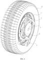
FIG. 1 is an overall structure diagram according to an embodiment of the present application. -
FIG. 2 is a top view of the overall structure according to an embodiment of the present application. -
FIG. 3 is a section view along A-A line inFIG. 2 . -
FIG. 4 is a schematic view of a tire after rotation of 90° according to an embodiment of the present application. - The present application is further described in detail below in combination with
FIGs. 1-4 . - An embodiment of the present application discloses a layout structure of swing arm assembly. Referring to
FIG. 1 , the layout structure of swing arm assembly includes arim 1, ahub motor 2, asteering knuckle 3, abrake disc 6 and a swing arm component. Atire 11 is installed at therim 1, and thehub motor 2 is located in therim 1. Therim 1 is fixedly connected to a rotor of thehub motor 2 by a bolt, and thesteering knuckle 3 is fixedly connected to astator 21 of thehub motor 2 and located at thehub motor 2 close to the inside of a vehicle. - Referring to
FIG. 1 ,FIG. 2 andFIG. 3 , the swing arm component includes anupper swing arm 4 and alower swing arm 5. A first end of thelower swing arm 5 is connected to a vehicle subframe, and a second end thereof is universally connected with thestator 21 of thehub motor 2 to form afirst hinge point 71. A first end of theupper swing arm 4 is connected to the vehicle subframe, and a second end thereof is universally connected with thesteering knuckle 3 to form asecond hinge point 72. Thefirst hinge point 71 and thesecond hinge point 72 are located in a same vertical plane, and a connection line between thefirst hinge point 71 and thesecond hinge point 72 constitutes avirtual kingpin axis 73. Thevirtual kingpin axis 73 is crossed with anaxis 12 of therim 1, an intersection of thevirtual kingpin axis 73 and the ground is coincided with agrounding center 13 of thetire 11. - Referring to
FIG. 2 andFIG. 3 , when the connection line between thefirst hinge point 71 and thesecond hinge point 72 is coincided with thegrounding center 13 of thetire 11, a kingpin offset is zero, and a steering resistance torque of the vehicle is minimum, which can effectively reduce abrasion of the tire11. Reduction of the kingpin offset may lead to a small change of the suspension alignment parameters when thetire 11 jumps, which finally improves the dynamic response capability, the braking performance, the handling and the stability of the running track of thetire 11 of the whole vehicle. - Referring to
FIG. 3 , the layout structure of the present application can also be so configured, that the distance from the intersection of thevirtual kingpin axis 73 and the ground to the center of thetire 11 can be changed by fine adjustment of the locations of thefirst hinge point 71 and thesecond hinge point 72, to adjust the kingpin offset, such that the kingpin offset can be adaptively modified according to requirements of different vehicles to meet chassis tuning requirements of different vehicles. - Referring to
FIG. 1 andFIG. 3 , thesteering knuckle 3 includes aconnection ring 31 and an extension arm 32 which are integrally formed. Theconnection ring 31 is fixedly connected to thehub motor 2 and is coaxially arranged with therim 1. The extension arm 32 is located directly above the axis of theconnection ring 31. A first end of the extension arm 32 is connected to theconnection ring 31, while a second end thereof is inclined upward and is integrally formed with afirst connection portion 33. Thefirst connection portion 33 extends horizontally and is fastened with an upper ball joint 34. An end of theupper swing arm 4 close to thesteering knuckle 3 is universally connected with the upper ball joint 34. - Referring to
FIG. 1 , theupper swing arm 4 includesfirst connection arms 41 and asecond connection arm 42 which are integrally formed. Thefirst connection arms 41 extend horizontally along the transverse direction of vehicle. It is provided with twofirst connection arms 41 parallel to each other along the longitudinal direction of vehicle, the twofirst connection arms 41 are located in a same horizontal plane. All thefirst connection arms 41 are located at a side of thesteering knuckle 3 close to the front or rear of the vehicle. In this embodiment, all thefirst connection arms 41 are located at a side of thesteering knuckle 3 close to the front of the vehicle. And the first connection arms extend at an obtuse angle to thesecond connection arm 42. A connection between thefirst connection arms 41 and thesecond connection arm 42 is configured as an arc-shaped transition. Thelower swing arm 5 has a same structure as theupper swing arm 4, and thelower swing arm 5 is located below theupper swing arm 4. - Referring to
FIG. 1 andFIG. 4 , in this embodiment, all thefirst connection arms 41 are arranged at the side of thesteering knuckle 3 close to the front of the vehicle, and thefirst connection arms 41 extend at an obtuse angle to thesecond connection arm 42. Theupper swing arm 4 is so configured, that the connection between theupper swing arm 4 and thesteering knuckle 3 is located at theupper swing arm 3 farthest away from the front of the vehicle. When thesteering knuckle 3 is turned around the upper ball joint 34, thetire 11 does not intend to interfere with theupper swing arm 4, which can increase the steering angle of the vehicle to the maximum. The steering angle of thetire 11 can reach 90°, to achieve the steering requirements of distributed driving of various drive-modes such as turning around in place, lateral driving, normal driving, and the like. - Referring to
FIG. 1 andFIG. 4 , a side of thehub motor 2 close to the inside of the vehicle is provided with abrake disc 6, which is coaxially and fixedly connected with aconnection shaft 61. Theconnection shaft 61 is coaxially and fixedly connected to the rotor of thehub motor 2, and thebrake disc 6 is located between theupper swing arm 4 and thelower swing arm 5. Thelower swing arm 5 is connected to thestator 21 of thehub motor 2, which leads to a smaller distance between thelower swing arm 5 and thebrake disc 6. In order to prevent an interference between thelower swing arm 5 and thebrake disc 6, an end of thelower swing arm 5 is integrally formed with a swingarm connection portion 51, the swingarm connection portion 51 extends vertically. Thestator 21 of thehub motor 2 is fixedly provided with a lower ball joint 22 located directly below the axis of thehub motor 2, and the top end of the swingarm connection portion 51 is universally connected with the lower ball joint 22. - Referring to
FIG. 1 andFIG. 4 , the swingarm connection portion 51 extends vertically, such that an end of thelower swing arm 5 close to thehub motor 2 is shaped in form of "L", which increases a vertical distance between thelower swing arm 5 and thebrake disc 6 and reduces a possibility of an interference between thelower swing arm 5 and a brake assembly. Swingarm connection portions 51 with different vertical heights can also be applied according to the diameter of thebrake disc 6, to meet different requirements of users. - The implementation principle of the layout structure of swing arm assembly in the embodiment of the present application is that the upper ball joint 34 is provided above the
steering knuckle 3, theupper swing arm 4 is universally connected with the upper ball joint 34 to form thesecond hinge point 72. The lower ball joint 22 is fixedly provided at thestator 21 of thehub motor 2, thelower swing arm 5 is universally connected with the lower ball joint 22 to form thefirst hinge point 71. Thefirst hinge point 71 is lower than thesecond hinge point 72, and located at a side of thesecond hinge point 72 close to the inside of the vehicle, so that the connection line between thefirst hinge point 71 and thesecond hinge point 72 constitutes thevirtual kingpin axis 73, and the intersection of thevirtual kingpin axis 73 and the ground is coincided with a center plane of thetire 11, which greatly reduces the kingpin offset. - The kingpin offset is decreased, such that the steering resistance torque is decreased, which can effectively reduce abrasion of the
tire 11. Meanwhile, the reduction of the kingpin offset may lead to a smaller change of the suspension alignment parameters when wheel jumps, which finally improves the dynamic response capability, the braking performance, the handling and the stability of running track of thetire 11 of the whole vehicle. - In addition, if the layout form of the
upper swing arm 4 and thelower swing arm 5 in the present application is combined with enough steering space, a large steering angle can be achieved by an electric vehicle withhub motor 2 without intending to interfere, which meets the steering requirements of distributed driving of various drive-modes. - The above are the preferred embodiments of the present application, which are not intended to limit the protection scope of the present application. Therefore, all equivalent changes made according to the structure, shape and principle of the present application should be covered within the protection scope of the present application.
-
- 1
- rim
- 11
- tire
- 12
- axis
- 13
- grounding center
- 2
- hub motor
- 21
- rotor
- 22
- lower ball joint
- 3
- steering knuckle
- 31
- connection ring
- 32
- extension arm
- 33
- first connection portion
- 34
- upper ball joint
- 4
- upper swing arm
- 41
- first connection arm
- 42
- second connection arm
- 5
- lower swing arm
- 51
- swing arm connection portion
- 6
- brake disc
- 61
- connection shaft
- 71
- first hinge point
- 72
- second hinge point
- 73
- virtual kingpin axis
Claims (9)
- A layout structure of swing arm assembly, comprising a rim (1), a hub motor (2), a steering knuckle (3), and a swing arm component, characterized in that a tire (11) is mounted at the rim (1), the hub motor (2) is located in the rim (1), the rim (1) is connected to a rotor of the hub motor (2); the steering knuckle (3) is fixedly connected to a stator (21) of the hub motor (2) at a position close to an inside of a vehicle; the swing arm component comprises an upper swing arm (4) connected between the steering knuckle (3) and a vehicle subframe, as well as a lower swing arm (5) connected between the stator (21) of the hub motor (2) and the vehicle subframe; the lower swing arm (5) is universally connected with the stator (21) of the hub motor (2) to form a first hinge point (71), the upper swing arm (4) is universally connected with the steering knuckle (3) to form a second hinge point (72), a connection line between the first hinge point (71) and the second hinge point (72) constitutes a virtual kingpin axis (73), and a top end of the virtual kingpin axis (73) is inclined towards the inside of the vehicle.
- The layout structure of swing arm assembly according to claim 1, characterized in that the connection line between the first hinge point (71) and the second hinge point (72) is coincided with a grounding center (13) of the tire (11).
- The layout structure of swing arm assembly according to claim 1, characterized in that the steering knuckle (3) comprises a connection ring (31) fixedly connected to the hub motor (2) and an extension arm (32) on the connection ring (31); a side of the extension arm (32) close to the upper swing arm (4) is inclined upward and configured with a horizontal first connection portion (33); the first connection portion (33) is configured with an upper ball joint (34), and an end of the upper swing arm (4) close to the steering knuckle (3) is universally connected with the upper ball joint (34).
- The layout structure of swing arm assembly according to claim 3, characterized in that the connection ring (31), the extension arm (32) and the first connection portion (33) are integrally-formed.
- The layout structure of swing arm assembly according to claim 3, characterized in that the upper swing arm (4) comprises two first connection arms (41) extending horizontally along a transverse direction of the vehicle and a second connection arm (42) for connecting the first connection arms (41) and the steering knuckle (3); the two first connection arms (41) extend parallel to each other along a longitudinal direction of the vehicle, all the first connection arms (41) are located at a side of the steering knuckle (3) close to front or rear of the vehicle; and the first connection arms (41) extend at an obtuse angle to the second connection arm (42).
- The layout structure of swing arm assembly according to claim 5, characterized in that the first connection arms (41) and the second connection arm (42) are integrally-formed, and a connection between the first connection arms (41) and the second connection arm (42) is configured as an arc-shaped transition.
- The layout structure of swing arm assembly according to claim 1, characterized in that a side of the hub motor (2) close to the inside of the vehicle is provided with a brake disc (6), the brake disc (6) is coaxially connected to the rotor of the hub motor (2); the brake disc (6) is located between the upper swing arm (4) and the lower swing arm (5), an end of the lower swing arm (5) is provided with a swing arm connection portion (51), the swing arm connection portion (51) extends vertically; the stator (21) of the hub motor (2) is provided with a lower ball joint (22), and a top end of the swing arm connection portion (51) is universally connected with the lower ball joint (22).
- The layout structure of swing arm assembly according to claim 7, characterized in that the swing arm connection portion (51) is integrally formed with the lower swing arm (5).
- The layout structure of swing arm assembly according to claim 5, characterized in that the lower swing arm (5) has a same structure as the upper swing arm (4).
Applications Claiming Priority (1)
| Application Number | Priority Date | Filing Date | Title |
|---|---|---|---|
| CN202310250654.9A CN116238276B (en) | 2023-03-15 | 2023-03-15 | Swing arm assembly arrangement structure of automobile with hub motor |
Publications (1)
| Publication Number | Publication Date |
|---|---|
| EP4431316A1 true EP4431316A1 (en) | 2024-09-18 |
Family
ID=86624072
Family Applications (1)
| Application Number | Title | Priority Date | Filing Date |
|---|---|---|---|
| EP23191322.9A Pending EP4431316A1 (en) | 2023-03-15 | 2023-08-14 | Layout structure of swing arm assembly |
Country Status (4)
| Country | Link |
|---|---|
| US (1) | US11919588B1 (en) |
| EP (1) | EP4431316A1 (en) |
| JP (1) | JP7491625B1 (en) |
| CN (1) | CN116238276B (en) |
Citations (3)
| Publication number | Priority date | Publication date | Assignee | Title |
|---|---|---|---|---|
| JP2013144509A (en) * | 2012-01-16 | 2013-07-25 | Nissan Motor Co Ltd | Motor feeder wiring structure of in-wheel motor driving wheel |
| EP3112194A1 (en) * | 2014-02-27 | 2017-01-04 | NTN Corporation | Structure for linking in-wheel motor drive device and damper, and suspension device provided with said linking structure |
| US20200207405A1 (en) * | 2018-12-27 | 2020-07-02 | Toyota Jidosha Kabushiki Kaisha | Steering device and vehicle wheel mounting module including the same |
Family Cites Families (36)
| Publication number | Priority date | Publication date | Assignee | Title |
|---|---|---|---|---|
| JP3094345B2 (en) * | 1991-10-29 | 2000-10-03 | 東京電力株式会社 | Wheel motor |
| JP2003300420A (en) | 2002-04-10 | 2003-10-21 | Hiroshi Shimizu | In-wheel motor of electric automobile |
| JP4133186B2 (en) * | 2002-10-02 | 2008-08-13 | 株式会社ブリヂストン | In-wheel motor system for steering wheels |
| JP4225134B2 (en) | 2003-06-25 | 2009-02-18 | トヨタ自動車株式会社 | Vehicle suspension system |
| JP4628136B2 (en) * | 2004-02-26 | 2011-02-09 | トヨタ自動車株式会社 | Wiring device |
| JP4276579B2 (en) * | 2004-05-17 | 2009-06-10 | トヨタ自動車株式会社 | Mounting structure of components installed in in-wheel motor |
| JP2005329817A (en) | 2004-05-20 | 2005-12-02 | Honda Motor Co Ltd | Wheel drive device for vehicle |
| JP4694148B2 (en) | 2004-05-28 | 2011-06-08 | トヨタ自動車株式会社 | Motor parts |
| JP2006188153A (en) * | 2005-01-06 | 2006-07-20 | Toyota Motor Corp | In-wheel motor |
| JP2007161022A (en) * | 2005-12-12 | 2007-06-28 | Bridgestone Corp | In-wheel motor system |
| JP2008168804A (en) | 2007-01-12 | 2008-07-24 | Mazda Motor Corp | Arrangement structure of vehicle drive device |
| JP2009040208A (en) | 2007-08-08 | 2009-02-26 | Bridgestone Corp | Vehicle suspension device |
| JP2009248902A (en) | 2008-04-10 | 2009-10-29 | Toyota Motor Corp | Power supply structure of in-wheel motor |
| JP2013103665A (en) | 2011-11-16 | 2013-05-30 | Nissan Motor Co Ltd | Steering device of in-wheel motor drive wheel |
| US9796235B2 (en) * | 2013-04-30 | 2017-10-24 | Nissan Motor Co., Ltd. | Suspension device for in-wheel motor driven wheel |
| US9302577B2 (en) * | 2013-08-29 | 2016-04-05 | Roberto Sanchez Catalan | Halbach array electric motor with substantially contiguous electromagnetic cores |
| JP2016022756A (en) | 2014-07-16 | 2016-02-08 | Ntn株式会社 | Steering system with in-wheel motor of amphibious vehicle |
| CN204263873U (en) * | 2014-11-10 | 2015-04-15 | 同济大学 | A kind of energy pair of transverse arm active suspension |
| EP3287306B1 (en) | 2015-04-20 | 2020-04-08 | FOMM Corporation | Vehicle suspension structure |
| JP6613056B2 (en) | 2015-06-04 | 2019-11-27 | Ntn株式会社 | Suspension structure for in-wheel motor drive |
| CN105539042B (en) * | 2016-01-20 | 2018-08-10 | 武汉科技大学 | The double trailing arm type suspension of In-wheel motor driving automobile for wide-angle deflecting roller |
| ITUA20163542A1 (en) * | 2016-05-18 | 2017-11-18 | Brist Axle Systems S R L | INDEPENDENT SUSPENSION FOR VEHICLES, IN PARTICULAR A SUSPENSION FOR A STEERING WHEEL OF VEHICLES |
| CN106585306B (en) * | 2016-11-08 | 2019-01-25 | 同济大学 | An integrated wire-controlled independent steering system based on double wishbone suspension |
| CN106627102A (en) * | 2017-02-10 | 2017-05-10 | 中国第汽车股份有限公司 | Wheel hub motor driving device |
| JP7064702B2 (en) | 2018-06-12 | 2022-05-11 | マツダ株式会社 | Induction motor |
| CN108909388A (en) * | 2018-09-21 | 2018-11-30 | 吉林大学 | A kind of suspension angle assembly of hub motor driven electric vehicle |
| LU101111B1 (en) * | 2019-01-29 | 2020-07-29 | Alpha Ec Ind 2018 S A R L | Bus steering system |
| CN110861458B (en) * | 2019-11-12 | 2024-01-19 | 艾德斯汽车电机无锡有限公司 | Gravity power generation technology in suspension structure |
| CN111186274A (en) * | 2020-01-21 | 2020-05-22 | 同济大学 | An electric wheel McPherson suspension structure with adjustable kingpin axis position |
| CN111186270B (en) * | 2020-01-22 | 2022-09-20 | 同济大学 | Electric wheel independent suspension structure with four control arms |
| CN112659837A (en) * | 2020-12-24 | 2021-04-16 | 浙江亚太智能网联汽车创新中心有限公司 | Suspension assembly suitable for in-wheel motor driven steering wheel and electric vehicle |
| CN216185453U (en) | 2021-04-12 | 2022-04-05 | 永康市凌鹰电器有限公司 | All-terrain vehicle hub brake steering mechanism |
| JP7589652B2 (en) | 2021-06-28 | 2024-11-26 | トヨタ自動車株式会社 | Vehicle Control Systems |
| KR102430176B1 (en) * | 2022-01-25 | 2022-08-11 | 주식회사 만도 | Wheel module and vehicle comprising the same |
| JP2023111214A (en) | 2022-01-31 | 2023-08-10 | 株式会社デンソー | Wheel unit, in-wheel motor |
| CN114670920A (en) | 2022-03-14 | 2022-06-28 | 吉林大学 | An automatic wheel module for a skateboard chassis |
-
2023
- 2023-03-15 CN CN202310250654.9A patent/CN116238276B/en active Active
- 2023-08-14 EP EP23191322.9A patent/EP4431316A1/en active Pending
- 2023-08-16 JP JP2023132731A patent/JP7491625B1/en active Active
- 2023-08-18 US US18/235,479 patent/US11919588B1/en active Active
Patent Citations (3)
| Publication number | Priority date | Publication date | Assignee | Title |
|---|---|---|---|---|
| JP2013144509A (en) * | 2012-01-16 | 2013-07-25 | Nissan Motor Co Ltd | Motor feeder wiring structure of in-wheel motor driving wheel |
| EP3112194A1 (en) * | 2014-02-27 | 2017-01-04 | NTN Corporation | Structure for linking in-wheel motor drive device and damper, and suspension device provided with said linking structure |
| US20200207405A1 (en) * | 2018-12-27 | 2020-07-02 | Toyota Jidosha Kabushiki Kaisha | Steering device and vehicle wheel mounting module including the same |
Also Published As
| Publication number | Publication date |
|---|---|
| US11919588B1 (en) | 2024-03-05 |
| CN116238276A (en) | 2023-06-09 |
| JP2024132797A (en) | 2024-10-01 |
| CN116238276B (en) | 2024-08-13 |
| JP7491625B1 (en) | 2024-05-28 |
Similar Documents
| Publication | Publication Date | Title |
|---|---|---|
| US9731572B2 (en) | Suspension device for an in-wheel motor driven wheel | |
| CN109050660A (en) | A kind of knuckle of automobile steering roller, transfer and automobile | |
| CN111186274A (en) | An electric wheel McPherson suspension structure with adjustable kingpin axis position | |
| CN106627102A (en) | Wheel hub motor driving device | |
| CN111186270B (en) | Electric wheel independent suspension structure with four control arms | |
| CN110816658B (en) | Front suspension system of direct-drive hub motor vehicle | |
| CN112238895A (en) | Independent steering system with steering motor arranged on equal-length double-trailing-arm suspension knuckle | |
| EP3287306B1 (en) | Vehicle suspension structure | |
| CN201494493U (en) | Wheel-side integrated driving and steering vehicle running mechanism | |
| CN117400717B (en) | A wheel side module system | |
| CN206436815U (en) | A kind of wheel motor drive device | |
| US11919588B1 (en) | Layout structure of swing arm assembly | |
| US20250256541A1 (en) | Rear suspension system | |
| CN112659837A (en) | Suspension assembly suitable for in-wheel motor driven steering wheel and electric vehicle | |
| CN214928774U (en) | Electric vehicle steering system driven by hub motor and electric vehicle | |
| CN214420156U (en) | Suspension structure for driving steering wheel by hub motor and electric vehicle | |
| CN118254865A (en) | Four-wheel independent steering system of wheel edge driving motor double-fork arm suspension | |
| CN207241414U (en) | A kind of chassis motorized structure using multi-connecting-rod separated suspension | |
| JP4168818B2 (en) | Suspension device for motor-driven vehicle | |
| CN212267624U (en) | Turn to trapezoidal mechanism and car | |
| KR20230038954A (en) | Suspension device for in-wheel motor | |
| CN223199802U (en) | Four-wheel independent steering distributed driving chassis platform | |
| KR20220159556A (en) | Suspension device for in-wheel motor | |
| KR102717360B1 (en) | Independent steering suspension device provided in the vehicle | |
| CN120840385A (en) | A highly integrated vehicle wheel corner module and vehicle |
Legal Events
| Date | Code | Title | Description |
|---|---|---|---|
| STAA | Information on the status of an ep patent application or granted ep patent |
Free format text: STATUS: EXAMINATION IS IN PROGRESS |
|
| PUAI | Public reference made under article 153(3) epc to a published international application that has entered the european phase |
Free format text: ORIGINAL CODE: 0009012 |
|
| 17P | Request for examination filed |
Effective date: 20230814 |
|
| AK | Designated contracting states |
Kind code of ref document: A1 Designated state(s): AL AT BE BG CH CY CZ DE DK EE ES FI FR GB GR HR HU IE IS IT LI LT LU LV MC ME MK MT NL NO PL PT RO RS SE SI SK SM TR |
|
| GRAP | Despatch of communication of intention to grant a patent |
Free format text: ORIGINAL CODE: EPIDOSNIGR1 |
|
| STAA | Information on the status of an ep patent application or granted ep patent |
Free format text: STATUS: GRANT OF PATENT IS INTENDED |
|
| INTG | Intention to grant announced |
Effective date: 20260202 |