EP4431121A1 - Sterilization system, air conditioner, sterilization method, and sterilization program - Google Patents
Sterilization system, air conditioner, sterilization method, and sterilization program Download PDFInfo
- Publication number
- EP4431121A1 EP4431121A1 EP22906881.2A EP22906881A EP4431121A1 EP 4431121 A1 EP4431121 A1 EP 4431121A1 EP 22906881 A EP22906881 A EP 22906881A EP 4431121 A1 EP4431121 A1 EP 4431121A1
- Authority
- EP
- European Patent Office
- Prior art keywords
- irradiation
- time
- sterilization
- case
- air conditioner
- Prior art date
- Legal status (The legal status is an assumption and is not a legal conclusion. Google has not performed a legal analysis and makes no representation as to the accuracy of the status listed.)
- Pending
Links
Images


Classifications
-
- F—MECHANICAL ENGINEERING; LIGHTING; HEATING; WEAPONS; BLASTING
- F24—HEATING; RANGES; VENTILATING
- F24F—AIR-CONDITIONING; AIR-HUMIDIFICATION; VENTILATION; USE OF AIR CURRENTS FOR SCREENING
- F24F13/00—Details common to, or for air-conditioning, air-humidification, ventilation or use of air currents for screening
- F24F13/22—Means for preventing condensation or evacuating condensate
-
- C—CHEMISTRY; METALLURGY
- C02—TREATMENT OF WATER, WASTE WATER, SEWAGE, OR SLUDGE
- C02F—TREATMENT OF WATER, WASTE WATER, SEWAGE, OR SLUDGE
- C02F1/00—Treatment of water, waste water, or sewage
- C02F1/30—Treatment of water, waste water, or sewage by irradiation
- C02F1/32—Treatment of water, waste water, or sewage by irradiation with ultraviolet light
-
- F—MECHANICAL ENGINEERING; LIGHTING; HEATING; WEAPONS; BLASTING
- F24—HEATING; RANGES; VENTILATING
- F24F—AIR-CONDITIONING; AIR-HUMIDIFICATION; VENTILATION; USE OF AIR CURRENTS FOR SCREENING
- F24F11/00—Control or safety arrangements
- F24F11/30—Control or safety arrangements for purposes related to the operation of the system, e.g. for safety or monitoring
-
- F—MECHANICAL ENGINEERING; LIGHTING; HEATING; WEAPONS; BLASTING
- F24—HEATING; RANGES; VENTILATING
- F24F—AIR-CONDITIONING; AIR-HUMIDIFICATION; VENTILATION; USE OF AIR CURRENTS FOR SCREENING
- F24F11/00—Control or safety arrangements
- F24F11/50—Control or safety arrangements characterised by user interfaces or communication
- F24F11/61—Control or safety arrangements characterised by user interfaces or communication using timers
-
- F—MECHANICAL ENGINEERING; LIGHTING; HEATING; WEAPONS; BLASTING
- F24—HEATING; RANGES; VENTILATING
- F24F—AIR-CONDITIONING; AIR-HUMIDIFICATION; VENTILATION; USE OF AIR CURRENTS FOR SCREENING
- F24F11/00—Control or safety arrangements
- F24F11/70—Control systems characterised by their outputs; Constructional details thereof
-
- F—MECHANICAL ENGINEERING; LIGHTING; HEATING; WEAPONS; BLASTING
- F24—HEATING; RANGES; VENTILATING
- F24F—AIR-CONDITIONING; AIR-HUMIDIFICATION; VENTILATION; USE OF AIR CURRENTS FOR SCREENING
- F24F13/00—Details common to, or for air-conditioning, air-humidification, ventilation or use of air currents for screening
- F24F13/22—Means for preventing condensation or evacuating condensate
- F24F13/222—Means for preventing condensation or evacuating condensate for evacuating condensate
-
- F—MECHANICAL ENGINEERING; LIGHTING; HEATING; WEAPONS; BLASTING
- F24—HEATING; RANGES; VENTILATING
- F24F—AIR-CONDITIONING; AIR-HUMIDIFICATION; VENTILATION; USE OF AIR CURRENTS FOR SCREENING
- F24F8/00—Treatment, e.g. purification, of air supplied to human living or working spaces otherwise than by heating, cooling, humidifying or drying
- F24F8/20—Treatment, e.g. purification, of air supplied to human living or working spaces otherwise than by heating, cooling, humidifying or drying by sterilisation
- F24F8/22—Treatment, e.g. purification, of air supplied to human living or working spaces otherwise than by heating, cooling, humidifying or drying by sterilisation using UV light
-
- A—HUMAN NECESSITIES
- A61—MEDICAL OR VETERINARY SCIENCE; HYGIENE
- A61L—METHODS OR APPARATUS FOR STERILISING MATERIALS OR OBJECTS IN GENERAL; DISINFECTION, STERILISATION OR DEODORISATION OF AIR; CHEMICAL ASPECTS OF BANDAGES, DRESSINGS, ABSORBENT PADS OR SURGICAL ARTICLES; MATERIALS FOR BANDAGES, DRESSINGS, ABSORBENT PADS OR SURGICAL ARTICLES
- A61L2/00—Disinfection or sterilisation of materials or objects, in general; Accessories therefor
- A61L2/02—Disinfection or sterilisation of materials or objects, in general; Accessories therefor using physical processes
- A61L2/08—Radiation
- A61L2/10—Ultraviolet [UV] radiation
-
- C—CHEMISTRY; METALLURGY
- C02—TREATMENT OF WATER, WASTE WATER, SEWAGE, OR SLUDGE
- C02F—TREATMENT OF WATER, WASTE WATER, SEWAGE, OR SLUDGE
- C02F2201/00—Apparatus for treatment of water, waste water or sewage
- C02F2201/32—Details relating to UV-irradiation devices
- C02F2201/322—Lamp arrangement
- C02F2201/3222—Units using UV-light emitting diodes [LED]
-
- C—CHEMISTRY; METALLURGY
- C02—TREATMENT OF WATER, WASTE WATER, SEWAGE, OR SLUDGE
- C02F—TREATMENT OF WATER, WASTE WATER, SEWAGE, OR SLUDGE
- C02F2201/00—Apparatus for treatment of water, waste water or sewage
- C02F2201/32—Details relating to UV-irradiation devices
- C02F2201/326—Lamp control systems
-
- C—CHEMISTRY; METALLURGY
- C02—TREATMENT OF WATER, WASTE WATER, SEWAGE, OR SLUDGE
- C02F—TREATMENT OF WATER, WASTE WATER, SEWAGE, OR SLUDGE
- C02F2209/00—Controlling or monitoring parameters in water treatment
- C02F2209/42—Liquid level
-
- C—CHEMISTRY; METALLURGY
- C02—TREATMENT OF WATER, WASTE WATER, SEWAGE, OR SLUDGE
- C02F—TREATMENT OF WATER, WASTE WATER, SEWAGE, OR SLUDGE
- C02F2209/00—Controlling or monitoring parameters in water treatment
- C02F2209/44—Time
-
- C—CHEMISTRY; METALLURGY
- C02—TREATMENT OF WATER, WASTE WATER, SEWAGE, OR SLUDGE
- C02F—TREATMENT OF WATER, WASTE WATER, SEWAGE, OR SLUDGE
- C02F2303/00—Specific treatment goals
- C02F2303/04—Disinfection
-
- F—MECHANICAL ENGINEERING; LIGHTING; HEATING; WEAPONS; BLASTING
- F24—HEATING; RANGES; VENTILATING
- F24F—AIR-CONDITIONING; AIR-HUMIDIFICATION; VENTILATION; USE OF AIR CURRENTS FOR SCREENING
- F24F13/00—Details common to, or for air-conditioning, air-humidification, ventilation or use of air currents for screening
- F24F13/22—Means for preventing condensation or evacuating condensate
- F24F2013/228—Treatment of condensate, e.g. sterilising
-
- Y—GENERAL TAGGING OF NEW TECHNOLOGICAL DEVELOPMENTS; GENERAL TAGGING OF CROSS-SECTIONAL TECHNOLOGIES SPANNING OVER SEVERAL SECTIONS OF THE IPC; TECHNICAL SUBJECTS COVERED BY FORMER USPC CROSS-REFERENCE ART COLLECTIONS [XRACs] AND DIGESTS
- Y02—TECHNOLOGIES OR APPLICATIONS FOR MITIGATION OR ADAPTATION AGAINST CLIMATE CHANGE
- Y02A—TECHNOLOGIES FOR ADAPTATION TO CLIMATE CHANGE
- Y02A50/00—TECHNOLOGIES FOR ADAPTATION TO CLIMATE CHANGE in human health protection, e.g. against extreme weather
- Y02A50/20—Air quality improvement or preservation, e.g. vehicle emission control or emission reduction by using catalytic converters
Definitions
- the present disclosure relates to a sterilization system, an air conditioner, a sterilization method, and a sterilization program.
- drain water remaining in a drain pan proliferation of microorganisms (bacteria, mold, or the like) is likely to occur and metabolites of the microorganisms may become slime. In such a case, a flow path for the drain water may be blocked or a drain pump may be clogged.
- a method of irradiating drain water with UV-C (LED) light to reduce the number of microorganisms has been examined.
- the life of an LED is short in many cases. For example, in a case where a cooling operation is performed for 24 hours and irradiation with UV-C light is performed constantly, the LED may reach the end of the life thereof in approximately one year. In a case where the LED reaches the end of the life thereof, a replacement operation needs to be performed.
- the present disclosure has been made in view of such circumstances and an object of the present disclosure is to provide a sterilization system, an air conditioner, a sterilization method, and a sterilization program with which it is possible to suppress microorganisms in drain water while extending the life of a UV irradiation device.
- a sterilization system including an irradiation control unit that controls intermittent irradiation in which irradiation is performed for an irradiation time of which a length is equal to or shorter than 22% of a length of a reference time, the irradiation is stopped for a predetermined stoppage time after the irradiation time, and the irradiation is performed after the stoppage time, the reference time being a time taken for a predetermined sterilization rate to be reached in a case where drain water in a drain pan of an air conditioner is continuously irradiated with UV light by a UV irradiation device.
- a sterilization method includes: performing irradiation for an irradiation time of which a length is equal to or shorter than 22% of a length of a reference time, the reference time being a time taken for a predetermined sterilization rate to be reached in a case where drain water in a drain pan of an air conditioner is continuously irradiated with UV light by a UV irradiation device; stopping the irradiation for a predetermined stoppage time after the irradiation time; and performing the irradiation after the stoppage time.
- a sterilization program causes a computer to execute a process of performing irradiation for an irradiation time of which a length is equal to or shorter than 22% of a length of a reference time, stopping the irradiation for a predetermined stoppage time after the irradiation time, and performing the irradiation after the stoppage time, the reference time being a time taken for a predetermined sterilization rate to be reached in a case where drain water in a drain pan of an air conditioner is continuously irradiated with UV light by a UV irradiation device.
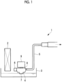
- Fig. 1 is a view showing a schematic configuration of an air conditioner (air conditioner) 1 provided with a sterilization system according to a first embodiment of the present disclosure.
- the air conditioner 1 according to the present embodiment includes a heat exchanger 2, a drain pan 3, a drain pump 4, a pipe 5, and a UV irradiation device (hereinafter, will be referred to as an "LED") 6 as main components.
- the air conditioner 1 is provided with a control device 10.
- the air conditioner 1 is, for example, a separated-type air conditioner including an indoor unit and an outdoor unit and the components shown in Fig. 1 are provided in the indoor unit which is a ceiling-embedded type indoor unit or the like.
- the heat exchanger 2 is connected to a compressor (not shown), another heat exchanger (not shown), an expansion valve (not shown), and the like and forms a refrigerating cycle.
- the heat exchanger 2 functions as an evaporator, and air is guided into the heat exchanger 2 by a blower (not shown).
- heat is exchanged between a refrigerant flowing in a heat transfer tube provided in the heat exchanger 2 and the air passing through the heat exchanger 2 (in the vicinity of the heat transfer tube), so that the air passing through the heat exchanger 2 is cooled.
- liquefaction may occur due to condensation of moisture in the air since heat is absorbed from the air. Water (hereinafter, will be referred to as "drain water”) generated due to such liquefaction drips, due to gravity, onto the drain pan 3 provided on a lower side.
- the drain pan 3 stores the drain water generated in the heat exchanger 2 and is installed below the heat exchanger 2 so that the drain water dripping onto the drain pan 3 is stored.
- a water level gauge is provided in the drain pan 3. The water level gauge detects the storage water level of the drain water stored in the drain pan 3. The water level gauge prevents overflow. For example, cooling operation or dehumidification operation may be forcibly stopped based on a result obtained by using the water level gauge.
- the drain pump 4 is, for example, a centrifugal pump, a rotary blade (not shown) is accommodated in a pump housing, and the drain pump 4 is provided with a suction port 7 that is formed at a lower portion of the pump housing and through which the drain water is sucked in and a discharge port 8 through which the drain water sucked in is discharged. Furthermore, a motor 9 that drives the rotary blade is connected to the drain pump 4. The drain pump 4 sucks up the drain water through the suction port 7 by using a centrifugal force that is generated as the motor 9 drives the rotary blade and the drain pump 4 discharges the drain water through the discharge port 8.
- the pipe 5 is connected to the discharge port 8 of the drain pump 4.
- the drain water sucked up by the drain pump 4 is discharged to the outside of the indoor unit through the discharge port 8 and the pipe 5.
- the pipe 5 extends upward to guide the drain water to the outside of the indoor unit. That is, the drain pump 4 pumps up the drain water stored in the drain pan 3 to discharge the drain water to the outside of the indoor unit.
- the UV irradiation device (LED) 6 is a device that performs irradiation with UV light (ultraviolet rays). Specifically, the LED 6 is a UV-C LED and performs irradiation with UV-C light (deep ultraviolet rays). The LED 6 is attached, for example, in the vicinity of the suction port of the drain pump 4.
- the control device 10 controls the entire air conditioner 1.
- the control device 10 has a function (the sterilization system) of controlling the LED 6 to suppress microorganisms in the drain water.
- Fig. 2 is a schematic configuration diagram showing an example of the hardware configuration of the control device 10 according to an embodiment of the present disclosure.
- the control device 10 is a so-called computer and includes a central processing unit (CPU) 11, a main memory 12, a storage unit 13, an external interface 14, a communication interface 15, an input unit 16, a display unit 17, and the like, for example.
- CPU central processing unit
- main memory 12 main memory
- storage unit 13 an external interface 14
- communication interface 15 an input unit 16
- display unit 17 a display unit 17
- the above-described components are directly or indirectly connected to each other via a bus, and perform various processes in cooperation with each other.
- the CPU 11 controls the entire control device 10 by using an operating system (OS) stored in the storage unit 13 connected via the bus and performs various processes by executing various programs stored in the storage unit 13.
- OS operating system
- the main memory 12 is composed of a writable memory such as a cache memory or a random-access memory (RAM), and is used as a work region for the reading of an execution program of the CPU 11, the writing of processing data of the execution program, or the like.
- a writable memory such as a cache memory or a random-access memory (RAM)
- the storage unit 13 is a non-transitory storage medium (a non-transitory computer-readable storage medium), and is, for example, a read-only memory (ROM), a hard disk drive (HDD), a flash memory, or the like.
- the storage unit 13 stores, for example, an OS for controlling the entire device such as Windows (registered trademark), iOS (registered trademark), and Android (registered trademark), a basic input/output system (BIOS), various device drivers for hardware-operating peripheral equipment, various kinds of application software, various data, files, and the like.
- the storage unit 13 stores a program for realizing various processes and various data required for realizing various processes.
- the external interface 14 is an interface for connection to an external device.
- Examples of the external device include an external monitor, a USB memory, and an external HDD.
- an external monitor In an example shown in Fig. 1 , only one external interface is shown. However, a plurality of external interfaces may be provided.
- the communication interface 15 is connected to a network and communicates with other devices to function as an interface for transmission and reception of information.
- the communication interface 15 communicates with other devices in a wired or wireless manner.
- wireless communication include Bluetooth (registered trademark), Wi-Fi, and communication in which a dedicated communication protocol is used.
- wired communication include a wired local area network (LAN).
- the input unit 16 is, for example, a user interface for issuing an instruction such as a keyboard, a mouse, and a touch pad.
- the display unit 17 is, for example, a liquid-crystal display, an organic electroluminescence (EL) display, or the like.
- the display unit 17 may be a touch panel display overlaid with a touch panel.
- Fig. 3 is a functional block diagram showing the functions of the control device 10.
- the control device 10 includes an air conditioning control unit 21 and a sterilization control unit (the sterilization system) 22.
- the sterilization control unit 22 includes an irradiation control unit 23.
- the control device 10 is configured to include the sterilization control unit 22.
- the sterilization control unit 22 may be provided separately from the control device 10.
- the sterilization control unit 22 and the LED 6 may be configured as one module.
- the functions realized by the above-described units are realized by a processing circuitry.
- a series of processes for realizing functions described below is stored in the storage unit 13 in the form of a program (for example, a route instruction data creating program), as an example.
- the CPU 11 reads the program into the main memory 12 and executes information processing and a calculation process to realize various functions.
- the program may be installed in the storage unit 13 in advance, may be provided in a state of being stored in another computer-readable storage medium, or may be distributed via a wired or wireless communication unit.
- Examples of the computer-readable storage medium include a magnetic disk, a magneto-optical disk, a CD-ROM, a DVD-ROM, and a semiconductor memory.
- the air conditioning control unit 21 performs various controls with respect to the air conditioner 1. Specifically, the air conditioning control unit 21 controls the refrigerating cycle by switching between operation modes such as heating operation, cooling operation, and dehumidification operation.
- the irradiation control unit 23 controls irradiation performed by the LED 6 to suppress microorganisms in the drain water. Specifically, the irradiation control unit 23 performs irradiation for an irradiation time of which the length is equal to or shorter than 22% of the length of a reference time, the reference time being a time taken for a predetermined sterilization rate (disinfection rate) to be reached in a case where the drain water is continuously irradiated with UV light. Then, after the irradiation time elapses, the irradiation is stopped for a predetermined stoppage time and the irradiation is performed after the stoppage time elapses. That is, the irradiation control unit 23 controls intermittent irradiation performed with UV light.
- the predetermined sterilization rate is, for example, 99%, but can be optionally set.
- Fig. 4 is a diagram showing a relationship between the irradiation time and the number of residual bacteria in the present embodiment.
- Fig. 4 shows an example of intermittent irradiation, and a specific process such as the irradiation time is not limited to that shown in Fig. 4 .
- the irradiation control unit 23 performs intermittent irradiation with UV light. Particularly, the irradiation control unit 23 repeats performing irradiation for the irradiation time and stopping the irradiation for the stoppage time. The number of times of repetition during the intermittent irradiation is not limited.
- Fig. 4 shows a change in number of residual bacteria in a case where irradiation is performed and a change in number of residual bacteria in a case where irradiation is not performed.
- the number of residual bacteria in the case where the irradiation is not performed is the number of residual bacteria in the case of natural extinction of microorganisms or the like without an increase in number thereof.
- each irradiation time is 10 minutes and each stoppage time is 50 minutes is shown as an example.
- the irradiation control unit 23 repeats performing irradiation for 10 minutes, stopping irradiation for 50 minutes thereafter, performing irradiation for 10 minutes thereafter, ... and so forth.
- the total number of times of irradiation is seven, and the total irradiation time is 70 minutes.
- the number of residual bacteria is significantly reduced at the time of the first irradiation and the sterilization rate reaches 99% at the time of the second irradiation which is performed after stoppage (when 70 minutes elapse after the start). Thereafter, performing irradiation for a short time is intermittently repeated and thus the number of residual bacteria is effectively reduced.
- Fig. 5 is a diagram showing a relationship between the irradiation time and the number of residual bacteria in a reference example.
- irradiation with UV light is continuously performed for 70 minutes.
- Fig. 5 shows a change in number of residual bacteria in a case where irradiation is performed and a change in number of residual bacteria in a case where irradiation is not performed.
- the sterilization rate can reach 99%.
- irradiation needs to be performed for 70 minutes in the case of continuous irradiation. However, it is sufficient to perform irradiation for a total of 20 minutes in the case of intermittent irradiation. In the case of intermittent irradiation as shown in Fig. 4 , further sterilization can be performed in a case where irradiation is performed for a total of 70 minutes. Particularly, in a case where the LED 6 continuously performs irradiation for a long period of time, the output of the LED 6 may decrease due to an increase in temperature thereof. However, in the case of intermittent irradiation, the increase in temperature is suppressed because of the stoppage time and thus a time during which the output is high can be effectively used.
- the intermittent irradiation is performed as described above, it is possible to suppress a UV irradiation time while effectively performing sterilization. Since the life of the LED 6 is determined by the total irradiation time, the life of the LED 6 can be extended in the case of intermittent operation.
- the irradiation time is set based on the reference time.
- the reference time is a time taken for the predetermined sterilization rate to be reached in a case where irradiation with UV light is continuously performed.
- the sterilization rate reaches 99% when irradiation with UV light is continuously performed for 70 minutes. That is, for a sterilization rate of 99%, the reference time is 70 minutes.
- the sterilization rate relating to a case where the reference time is set can be applied without being limited to 99%.
- the irradiation time is set to be equal to or shorter than 22% of the reference time. Specifically, in a case where the reference time is 70 minutes, it is preferable that the irradiation time is 5 minutes or more and 15 minutes or less (10 minutes in the example shown in Fig. 4 ).
- a time longer than the irradiation time is set as the stoppage time in the case of the intermittent operation.
- the stoppage time is set to be equal to or longer than three times the irradiation time.
- the stoppage time is 50 minutes. Even in a case where the stoppage time is longer than the irradiation time as described above, a sufficient sterilization effect can be achieved.
- the useful life is, for example, a rated life.
- the rated life may be an irradiation time taken for the output of the LED to reach 70% of the initial output thereof or an irradiation time taken for the output of the LED to reach 50% of the initial output thereof. That is, the rated life is set as a reference for replacement of the LED 6.
- the useful life of the LED 6 is 5 or more and 10 or less in a case where the useful life of the air conditioner 1 is 10.
- the useful life of the air conditioner 1 is the useful life of the air conditioner 1 in a configuration other than the LED 6 (in a case where the LED 6 is not provided).
- the lower limit of the useful life of the LED 6 is set on the assumption that replacement is performed once until the end of the useful life of the air conditioner 1 is reached.
- the upper limit of the useful life of the LED 6 is set on the assumption that replacement is not performed even once until the end of the useful life of the air conditioner 1 is reached.
- the LED 6 can be replaced once (or zero times) until the end of the useful life of the air conditioner 1 is reached.
- the irradiation control unit 23 performs irradiation with a predetermined amount of light, which is equal to or greater than 5000 mW.sec and equal to or smaller than 90000 mW.sec, per unit time.
- the amount of light may be the amount of light from one LED or the total amount of light from a plurality of LEDs, and the configuration is not limited as long as irradiation with the predetermined amount of light is performed. For example, in a case where irradiation is performed for 10 minutes at 10 mW (min) and then irradiation is stopped for 60 minutes, 5143 mW.sec per unit time (60 minutes) is achieved. For example, in a case where irradiation is performed for 15 minutes at 50 mW (min) and then irradiation is stopped for 45 minutes, 90000 mW.sec per unit time (60 minutes) is achieved.
- irradiation with the predetermined amount of light which is equal to or greater than 5000 mW.sec and equal to or smaller than 90000 mW.sec, is performed per unit time in the case of intermittent irradiation, irradiation with an amount of light sufficient for sterilization can be performed.
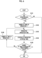
- FIG. 6 is a flowchart showing an example of the procedure for a sterilization process according to the present embodiment.
- the flow shown in Fig. 6 is repeatedly executed, for example, at a predetermined control cycle.
- a case where irradiation is performed 7 times in the form of intermittent irradiation will be described as an example.
- S101 it is determined whether or not the cooling operation or the dehumidification operation has been stopped (S101).
- a predetermined timing for example, an operation continuation time
- the result of the determination may be YES in a case where the cooling operation or the dehumidification operation is stopped (intermittent irradiation after stoppage of operation) or the result of the determination may be YES in a case where the predetermined timing is reached during the operation (intermittent irradiation during operation).
- the process is terminated.
- the cooling operation or the dehumidification operation is stopped (the result of the determination in S101 is YES)
- an intermittent irradiation process is started. First, the number of times of irradiation is set to 1 (S102). Then, irradiation is performed for the irradiation time (S103) .
- irradiation is stopped for the stoppage time (S104).
- it is determined whether or not the number of times of irradiation has reached a predetermined value (the number of times of irradiation 7) (S105) .
- the result of the determination in S105 is NO, 1 is added to the number of times of irradiation (S106) and S103 is executed.
- the result of the determination in S105 is YES, it is determined that irradiation has been performed seven times and the process is terminated.
- a case where irradiation is performed 7 times has been described.
- the number of times of irradiation is not limited.
- whether to terminate the process is performed based on the number of times of irradiation.
- the process may be terminated in a case where the total intermittent irradiation time reaches a predetermined time and a termination method is not limited.
- irradiation is performed for an irradiation time of which the length is equal to or shorter than 22% of the length of a reference time, the reference time being a time taken for a predetermined sterilization rate to be reached in a case where drain water is continuously irradiated with UV light. Then, the irradiation is stopped for a stoppage time and the irradiation is performed again thereafter. Accordingly, sterilization can be performed effectively even in a case where irradiation with UV light is not continuously performed for the reference time. In addition, since a time for which irradiation with UV light is performed is shortened, the life of the UV irradiation device can be extended.
- the irradiation control unit 23 in the present embodiment performs intermittent irradiation in a case where a predetermined standby time elapses after the end of intermittent irradiation. That is, the irradiation control unit 23 performs the intermittent irradiation as shown in Fig. 4 again after the standby time elapses.
- the irradiation control unit 23 performs intermittent irradiation in a case where the cooling operation or the dehumidification operation in the air conditioner 1 is not performed for the standby time after the end of intermittent irradiation.
- the standby time is set to be longer than a time for which an intermittent irradiation process is performed. For example, the standby time is set to 24 hours.
- a process of repeating the intermittent irradiation and the standby time is performed for a predetermined period of time.
- the predetermined period of time is set to, for example, 7 days in which drain water is expected to evaporate.
- the sterilization system the air conditioner, the sterilization method, and the sterilization program according to the present embodiment will be described focusing on differences between the first embodiment, the second embodiment, and the present embodiment.
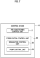
- the sterilization control unit 22 in the present embodiment includes a pump control unit 24.
- the pump control unit 24 operates, for a certain time, the drain pump 4 that sucks drain water in the drain pan 3.
- the pump control unit 24 operates the drain pump 4 for a predetermined time (about 1 minute) before irradiation with UV light.
- the drain water is sucked into the drain pump 4 as the drain pump 4 is driven. Then, in a case where the driving of the drain pump 4 is stopped, drain water that is sucked into the drain pump 4 and that is not discharged to the outside flows back to the drain pan 3. Accordingly, the drain water can be stirred.
- the drain pump 4 that sucks drain water in the drain pan 3 since the drain pump 4 that sucks drain water in the drain pan 3 is operated for a certain time, the drain water that is sucked into the drain pump 4 from the drain pan 3 and that is not completely sucked out flows back to the drain pan 3 and thus the drain water can be stirred. Accordingly, sterilization effect achieved by UV light can be improved.
- the sterilization system, the air conditioner, the sterilization method, and the sterilization program according to the present embodiment will be described focusing on differences between the first embodiment, the second embodiment, the third embodiment, and the present embodiment.
- the air conditioner 1 is provided with a sensor that detects the presence or absence of drain water in the drain pan 3.
- the sensor is, for example, an electrostatic sensor, a float switch, or the like. That is, the sensor detects that drain water is present in the drain pan 3.
- the irradiation control unit 23 performs irradiation in a case where the sensor detects that drain water is present in the drain pan 3. That is, intermittent irradiation is performed after the sensor confirms that there is drain water.
- the sensor may be provided as an individual device, or may be integrally configured with a module of the LED 6.
- the sensor may be incorporated into a module into which the sterilization control unit 22 and the LED 6 are incorporated.
- the function of the sterilization system can be added by adding the module to the existing air conditioner 1.
- irradiation is performed in a case where the sensor detects that drain water is present in the drain pan 3. Therefore, unnecessary irradiation with UV light can be suppressed.
- the sterilization system, the air conditioner, the sterilization method, and the sterilization program described in the above-described embodiments are understood as follows, for example.
- a sterilization system (22) includes an irradiation control unit (23) that controls intermittent irradiation in which irradiation is performed for an irradiation time of which a length is equal to or shorter than 22% of a length of a reference time, the irradiation is stopped for a predetermined stoppage time after the irradiation time, and the irradiation is performed after the stoppage time, the reference time being a time taken for a predetermined sterilization rate to be reached in a case where drain water in a drain pan (3) of an air conditioner (1) is continuously irradiated with UV light by a UV irradiation device (6).
- irradiation is performed for the irradiation time of which the length is equal to or shorter than 22% of the length of the reference time, the reference time being a time taken for the predetermined sterilization rate to be reached in a case where the drain water is continuously irradiated with UV light. Then, the irradiation is stopped for a stoppage time and the irradiation is performed again thereafter. Accordingly, sterilization can be performed effectively even in a case where irradiation with UV light is not continuously performed for the reference time. In addition, since a time for which irradiation with UV light is performed is shortened, the life of the UV irradiation device can be extended.
- the predetermined sterilization rate is, for example, 99%.
- the irradiation control unit may repeat performing irradiation for the irradiation time and stopping irradiation for the stoppage time.
- the stoppage time may be set to be equal to or longer than three times the irradiation time.
- the irradiation control unit may perform irradiation with a predetermined amount of light, which is equal to or greater than 5000 mW.sec and equal to or smaller than 90000 mW.sec, per unit time in the case of the intermittent irradiation.
- intermittent irradiation is performed with a predetermined amount of light, which is equal to or greater than 5000 mW.sec and equal to or smaller than 90000 mW.sec, per unit time in the case of the intermittent irradiation, it is possible to perform sterilization while suppressing the total amount of light in the case of the intermittent irradiation.
- the irradiation control unit may perform the intermittent irradiation in a case where a predetermined standby time elapses after the end of the intermittent irradiation.
- the irradiation control unit may perform the intermittent irradiation in a case where cooling operation or dehumidification operation in the air conditioner is not performed for the standby time after the end of the intermittent irradiation.
- microorganisms are likely to proliferate in a case where the cooling operation or the dehumidification operation in the air conditioner is not performed, since intermittent irradiation is performed in a case where the standby time elapses, it is possible to suppress proliferation of microorganisms.
- the sterilization system according to the present disclosure may further include a pump control unit (24) that operates, for a certain time, a drain pump (4) that sucks the drain water in the drain pan.
- a pump control unit (24) that operates, for a certain time, a drain pump (4) that sucks the drain water in the drain pan.
- the drain pump that sucks drain water in the drain pan since the drain pump that sucks drain water in the drain pan is operated for the certain time, the drain water that is sucked into the drain pump from the drain pan and that is not completely sucked out flows back to the drain pan and thus the drain water can be stirred. Accordingly, sterilization effect achieved by UV light can be improved.
- the irradiation control unit may perform irradiation in a case where a sensor detects that the drain water is present in the drain pan.
- irradiation is performed in a case where the sensor detects that drain water is present in the drain pan. Therefore, unnecessary irradiation with UV light can be suppressed.
- An air conditioner according to the present disclosure includes a drain pan, a UV irradiation device, and the above-described sterilization system.
- the useful life of the UV irradiation device may be 5 or more and 10 or less in a case where the useful life of the air conditioner is 10.
- the UV irradiation device can be replaced once (or zero times) until the end of the useful life of the air conditioner is reached.
- the useful life may be a rated life.
- the useful life is the rated life
- a relationship between the useful life of the UV irradiation device and the useful life of the air conditioner can be appropriately set.
- a sterilization method includes: performing irradiation for an irradiation time of which a length is equal to or shorter than 22% of a length of a reference time, the reference time being a time taken for a predetermined sterilization rate to be reached in a case where drain water in a drain pan of an air conditioner is continuously irradiated with UV light by a UV irradiation device; stopping the irradiation for a predetermined stoppage time after the irradiation time; and performing the irradiation after the stoppage time.
- a sterilization program causes a computer to execute a process of performing irradiation for an irradiation time of which a length is equal to or shorter than 22% of a length of a reference time, stopping the irradiation for a predetermined stoppage time after the irradiation time, and performing the irradiation after the stoppage time, the reference time being a time taken for a predetermined sterilization rate to be reached in a case where drain water in a drain pan of an air conditioner is continuously irradiated with UV light by a UV irradiation device.
Landscapes
- Engineering & Computer Science (AREA)
- Chemical & Material Sciences (AREA)
- General Engineering & Computer Science (AREA)
- Mechanical Engineering (AREA)
- Combustion & Propulsion (AREA)
- Organic Chemistry (AREA)
- Water Supply & Treatment (AREA)
- Environmental & Geological Engineering (AREA)
- Health & Medical Sciences (AREA)
- Hydrology & Water Resources (AREA)
- Life Sciences & Earth Sciences (AREA)
- Toxicology (AREA)
- Human Computer Interaction (AREA)
- Air Conditioning Control Device (AREA)
- Devices For Blowing Cold Air, Devices For Blowing Warm Air, And Means For Preventing Water Condensation In Air Conditioning Units (AREA)
- Physical Water Treatments (AREA)
Abstract
Description
- The present disclosure relates to a sterilization system, an air conditioner, a sterilization method, and a sterilization program.
- In an air conditioner, an indoor unit is provided with a drain pan and drain water accumulated in the drain pan is discharged by a drain pump (for example, PTL 1).
- [PTL 1]
Japanese Unexamined Patent Application Publication No. 2008-190753 - In drain water remaining in a drain pan, proliferation of microorganisms (bacteria, mold, or the like) is likely to occur and metabolites of the microorganisms may become slime. In such a case, a flow path for the drain water may be blocked or a drain pump may be clogged.
- A method of irradiating drain water with UV-C (LED) light to reduce the number of microorganisms has been examined. However, the life of an LED is short in many cases. For example, in a case where a cooling operation is performed for 24 hours and irradiation with UV-C light is performed constantly, the LED may reach the end of the life thereof in approximately one year. In a case where the LED reaches the end of the life thereof, a replacement operation needs to be performed.
- The present disclosure has been made in view of such circumstances and an object of the present disclosure is to provide a sterilization system, an air conditioner, a sterilization method, and a sterilization program with which it is possible to suppress microorganisms in drain water while extending the life of a UV irradiation device. Solution to Problem
- According to a first aspect of the present disclosure, there is provided a sterilization system including an irradiation control unit that controls intermittent irradiation in which irradiation is performed for an irradiation time of which a length is equal to or shorter than 22% of a length of a reference time, the irradiation is stopped for a predetermined stoppage time after the irradiation time, and the irradiation is performed after the stoppage time, the reference time being a time taken for a predetermined sterilization rate to be reached in a case where drain water in a drain pan of an air conditioner is continuously irradiated with UV light by a UV irradiation device.
- According to a second aspect of the present disclosure, there is provided a sterilization method according to the present disclosure includes: performing irradiation for an irradiation time of which a length is equal to or shorter than 22% of a length of a reference time, the reference time being a time taken for a predetermined sterilization rate to be reached in a case where drain water in a drain pan of an air conditioner is continuously irradiated with UV light by a UV irradiation device; stopping the irradiation for a predetermined stoppage time after the irradiation time; and performing the irradiation after the stoppage time.
- According to a third aspect of the present disclosure, there is provided a sterilization program according to the present disclosure causes a computer to execute a process of performing irradiation for an irradiation time of which a length is equal to or shorter than 22% of a length of a reference time, stopping the irradiation for a predetermined stoppage time after the irradiation time, and performing the irradiation after the stoppage time, the reference time being a time taken for a predetermined sterilization rate to be reached in a case where drain water in a drain pan of an air conditioner is continuously irradiated with UV light by a UV irradiation device.
- According to the present disclosure, it is possible to suppress microorganisms in drain water while extending the life of a UV irradiation device.
-
-
Fig. 1 is a view showing a schematic configuration of an air conditioner provided with a sterilization system according to a first embodiment of the present disclosure. -
Fig. 2 is a schematic configuration diagram showing an example of the hardware configuration of a control device according to the first embodiment of the present disclosure. -
Fig. 3 is a functional block diagram showing the functions of the control device according to the first embodiment of the present disclosure. -
Fig. 4 is a diagram showing a relationship between an irradiation time and the number of residual bacteria according to the first embodiment of the present disclosure. -
Fig. 5 is a diagram showing a relationship between the irradiation time and the number of residual bacteria in a reference example. -
Fig. 6 is a flowchart showing an example of the procedure for a sterilization process according to the first embodiment of the present disclosure. -
Fig. 7 is a functional block diagram showing the functions of a control device according to a third embodiment of the present disclosure. - Hereinafter, a first embodiment of a sterilization system, an air conditioner, a sterilization method, and a sterilization program according to the present disclosure will be described with reference to the drawings.
-
Fig. 1 is a view showing a schematic configuration of an air conditioner (air conditioner) 1 provided with a sterilization system according to a first embodiment of the present disclosure. As shown inFig. 1 , theair conditioner 1 according to the present embodiment includes aheat exchanger 2, adrain pan 3, adrain pump 4, apipe 5, and a UV irradiation device (hereinafter, will be referred to as an "LED") 6 as main components. In addition, theair conditioner 1 is provided with acontrol device 10. In the present embodiment, theair conditioner 1 is, for example, a separated-type air conditioner including an indoor unit and an outdoor unit and the components shown inFig. 1 are provided in the indoor unit which is a ceiling-embedded type indoor unit or the like. It will be assumed that theheat exchanger 2 is connected to a compressor (not shown), another heat exchanger (not shown), an expansion valve (not shown), and the like and forms a refrigerating cycle. - The
heat exchanger 2 functions as an evaporator, and air is guided into theheat exchanger 2 by a blower (not shown). In addition, heat is exchanged between a refrigerant flowing in a heat transfer tube provided in theheat exchanger 2 and the air passing through the heat exchanger 2 (in the vicinity of the heat transfer tube), so that the air passing through theheat exchanger 2 is cooled. In theheat exchanger 2, liquefaction may occur due to condensation of moisture in the air since heat is absorbed from the air. Water (hereinafter, will be referred to as "drain water") generated due to such liquefaction drips, due to gravity, onto thedrain pan 3 provided on a lower side. - The
drain pan 3 stores the drain water generated in theheat exchanger 2 and is installed below theheat exchanger 2 so that the drain water dripping onto thedrain pan 3 is stored. A water level gauge is provided in thedrain pan 3. The water level gauge detects the storage water level of the drain water stored in thedrain pan 3. The water level gauge prevents overflow. For example, cooling operation or dehumidification operation may be forcibly stopped based on a result obtained by using the water level gauge. - The
drain pump 4 is, for example, a centrifugal pump, a rotary blade (not shown) is accommodated in a pump housing, and thedrain pump 4 is provided with asuction port 7 that is formed at a lower portion of the pump housing and through which the drain water is sucked in and adischarge port 8 through which the drain water sucked in is discharged. Furthermore, amotor 9 that drives the rotary blade is connected to thedrain pump 4. Thedrain pump 4 sucks up the drain water through thesuction port 7 by using a centrifugal force that is generated as themotor 9 drives the rotary blade and thedrain pump 4 discharges the drain water through thedischarge port 8. - The
pipe 5 is connected to thedischarge port 8 of thedrain pump 4. In addition, the drain water sucked up by thedrain pump 4 is discharged to the outside of the indoor unit through thedischarge port 8 and thepipe 5. Thepipe 5 extends upward to guide the drain water to the outside of the indoor unit. That is, thedrain pump 4 pumps up the drain water stored in thedrain pan 3 to discharge the drain water to the outside of the indoor unit. - The UV irradiation device (LED) 6 is a device that performs irradiation with UV light (ultraviolet rays). Specifically, the
LED 6 is a UV-C LED and performs irradiation with UV-C light (deep ultraviolet rays). TheLED 6 is attached, for example, in the vicinity of the suction port of thedrain pump 4. - The
control device 10 controls theentire air conditioner 1. In addition, thecontrol device 10 has a function (the sterilization system) of controlling theLED 6 to suppress microorganisms in the drain water. -
Fig. 2 is a schematic configuration diagram showing an example of the hardware configuration of thecontrol device 10 according to an embodiment of the present disclosure. As shown inFig. 1 , thecontrol device 10 is a so-called computer and includes a central processing unit (CPU) 11, amain memory 12, astorage unit 13, anexternal interface 14, acommunication interface 15, aninput unit 16, adisplay unit 17, and the like, for example. The above-described components are directly or indirectly connected to each other via a bus, and perform various processes in cooperation with each other. - For example, the CPU 11 controls the
entire control device 10 by using an operating system (OS) stored in thestorage unit 13 connected via the bus and performs various processes by executing various programs stored in thestorage unit 13. - For example, the
main memory 12 is composed of a writable memory such as a cache memory or a random-access memory (RAM), and is used as a work region for the reading of an execution program of the CPU 11, the writing of processing data of the execution program, or the like. - The
storage unit 13 is a non-transitory storage medium (a non-transitory computer-readable storage medium), and is, for example, a read-only memory (ROM), a hard disk drive (HDD), a flash memory, or the like. Thestorage unit 13 stores, for example, an OS for controlling the entire device such as Windows (registered trademark), iOS (registered trademark), and Android (registered trademark), a basic input/output system (BIOS), various device drivers for hardware-operating peripheral equipment, various kinds of application software, various data, files, and the like. Thestorage unit 13 stores a program for realizing various processes and various data required for realizing various processes. - The
external interface 14 is an interface for connection to an external device. Examples of the external device include an external monitor, a USB memory, and an external HDD. In an example shown inFig. 1 , only one external interface is shown. However, a plurality of external interfaces may be provided. - The
communication interface 15 is connected to a network and communicates with other devices to function as an interface for transmission and reception of information. - For example, the
communication interface 15 communicates with other devices in a wired or wireless manner. Examples of wireless communication include Bluetooth (registered trademark), Wi-Fi, and communication in which a dedicated communication protocol is used. Examples of wired communication include a wired local area network (LAN). - The
input unit 16 is, for example, a user interface for issuing an instruction such as a keyboard, a mouse, and a touch pad. - The
display unit 17 is, for example, a liquid-crystal display, an organic electroluminescence (EL) display, or the like. Thedisplay unit 17 may be a touch panel display overlaid with a touch panel. -
Fig. 3 is a functional block diagram showing the functions of thecontrol device 10. As shown inFig. 3 , thecontrol device 10 includes an airconditioning control unit 21 and a sterilization control unit (the sterilization system) 22. Thesterilization control unit 22 includes anirradiation control unit 23. In the present embodiment, thecontrol device 10 is configured to include thesterilization control unit 22. However, thesterilization control unit 22 may be provided separately from thecontrol device 10. For example, thesterilization control unit 22 and theLED 6 may be configured as one module. - For example, the functions realized by the above-described units are realized by a processing circuitry. For example, a series of processes for realizing functions described below is stored in the
storage unit 13 in the form of a program (for example, a route instruction data creating program), as an example. The CPU 11 reads the program into themain memory 12 and executes information processing and a calculation process to realize various functions. - The program may be installed in the
storage unit 13 in advance, may be provided in a state of being stored in another computer-readable storage medium, or may be distributed via a wired or wireless communication unit. Examples of the computer-readable storage medium include a magnetic disk, a magneto-optical disk, a CD-ROM, a DVD-ROM, and a semiconductor memory. - The air
conditioning control unit 21 performs various controls with respect to theair conditioner 1. Specifically, the airconditioning control unit 21 controls the refrigerating cycle by switching between operation modes such as heating operation, cooling operation, and dehumidification operation. - The
irradiation control unit 23 controls irradiation performed by theLED 6 to suppress microorganisms in the drain water. Specifically, theirradiation control unit 23 performs irradiation for an irradiation time of which the length is equal to or shorter than 22% of the length of a reference time, the reference time being a time taken for a predetermined sterilization rate (disinfection rate) to be reached in a case where the drain water is continuously irradiated with UV light. Then, after the irradiation time elapses, the irradiation is stopped for a predetermined stoppage time and the irradiation is performed after the stoppage time elapses. That is, theirradiation control unit 23 controls intermittent irradiation performed with UV light. The predetermined sterilization rate is, for example, 99%, but can be optionally set. - Since drain water is likely to be generated in the case of the cooling operation or the dehumidification operation, an intermittent irradiation process is started during the cooling operation or the dehumidification operation or after stoppage of such operation.
-
Fig. 4 is a diagram showing a relationship between the irradiation time and the number of residual bacteria in the present embodiment.Fig. 4 shows an example of intermittent irradiation, and a specific process such as the irradiation time is not limited to that shown inFig. 4 . As shown inFig. 4 , theirradiation control unit 23 performs intermittent irradiation with UV light. Particularly, theirradiation control unit 23 repeats performing irradiation for the irradiation time and stopping the irradiation for the stoppage time. The number of times of repetition during the intermittent irradiation is not limited. Irradiation times of which the lengths are the same as each other and stoppage times of which the lengths are the same as each other are repeated. However, irradiation times of which the lengths are different from each other and stoppage times of which the lengths are different from each other may be repeated.Fig. 4 shows a change in number of residual bacteria in a case where irradiation is performed and a change in number of residual bacteria in a case where irradiation is not performed. The number of residual bacteria in the case where the irradiation is not performed is the number of residual bacteria in the case of natural extinction of microorganisms or the like without an increase in number thereof. - In
Fig. 4 , a case where each irradiation time is 10 minutes and each stoppage time is 50 minutes is shown as an example. In this way, theirradiation control unit 23 repeats performing irradiation for 10 minutes, stopping irradiation for 50 minutes thereafter, performing irradiation for 10 minutes thereafter, ... and so forth. The total number of times of irradiation is seven, and the total irradiation time is 70 minutes. - In a case where the intermittent irradiation is performed, as shown in
Fig. 4 , the number of residual bacteria is significantly reduced at the time of the first irradiation and the sterilization rate reaches 99% at the time of the second irradiation which is performed after stoppage (when 70 minutes elapse after the start). Thereafter, performing irradiation for a short time is intermittently repeated and thus the number of residual bacteria is effectively reduced. -
Fig. 5 is a diagram showing a relationship between the irradiation time and the number of residual bacteria in a reference example. In the reference example, irradiation with UV light is continuously performed for 70 minutes.Fig. 5 shows a change in number of residual bacteria in a case where irradiation is performed and a change in number of residual bacteria in a case where irradiation is not performed. Even in a case where irradiation is continuously performed for 70 minutes as shown inFig. 5 , the sterilization rate can reach 99%. However, in the present embodiment, as shown inFig. 4 , it is possible to make the sterilization rate reach 99% by performing irradiation for 10 minutes twice with a stoppage period (50 minutes) provided as an interval. That is, in a case where a sterilization rate of 99% is used as a reference, irradiation needs to be performed for 70 minutes in the case of continuous irradiation. However, it is sufficient to perform irradiation for a total of 20 minutes in the case of intermittent irradiation. In the case of intermittent irradiation as shown inFig. 4 , further sterilization can be performed in a case where irradiation is performed for a total of 70 minutes. Particularly, in a case where theLED 6 continuously performs irradiation for a long period of time, the output of theLED 6 may decrease due to an increase in temperature thereof. However, in the case of intermittent irradiation, the increase in temperature is suppressed because of the stoppage time and thus a time during which the output is high can be effectively used. - In a case where the intermittent irradiation is performed as described above, it is possible to suppress a UV irradiation time while effectively performing sterilization. Since the life of the
LED 6 is determined by the total irradiation time, the life of theLED 6 can be extended in the case of intermittent operation. - Since there is a stoppage time, intermittent irradiation can result in effective sterilization in comparison with continuous irradiation because of natural convection of the drain water during the stoppage time.
- Next, the setting of the irradiation time will be described.
- The irradiation time is set based on the reference time. The reference time is a time taken for the predetermined sterilization rate to be reached in a case where irradiation with UV light is continuously performed. In the reference example shown in
Fig. 5 , the sterilization rate reaches 99% when irradiation with UV light is continuously performed for 70 minutes. That is, for a sterilization rate of 99%, the reference time is 70 minutes. The sterilization rate relating to a case where the reference time is set can be applied without being limited to 99%. - Here, as shown in
Fig. 4 , a sterilization effect can be achieved without continuous irradiation. Therefore, the irradiation time is set to be equal to or shorter than 22% of the reference time. Specifically, in a case where the reference time is 70 minutes, it is preferable that the irradiation time is 5 minutes or more and 15 minutes or less (10 minutes in the example shown inFig. 4 ). - A time longer than the irradiation time is set as the stoppage time in the case of the intermittent operation. Specifically, the stoppage time is set to be equal to or longer than three times the irradiation time. In the example shown in
Fig. 4 , the stoppage time is 50 minutes. Even in a case where the stoppage time is longer than the irradiation time as described above, a sufficient sterilization effect can be achieved. - Next, the useful life of the
LED 6 will be described. - The useful life is, for example, a rated life. The rated life may be an irradiation time taken for the output of the LED to reach 70% of the initial output thereof or an irradiation time taken for the output of the LED to reach 50% of the initial output thereof. That is, the rated life is set as a reference for replacement of the
LED 6. - The useful life of the
LED 6 is 5 or more and 10 or less in a case where the useful life of theair conditioner 1 is 10. The useful life of theair conditioner 1 is the useful life of theair conditioner 1 in a configuration other than the LED 6 (in a case where theLED 6 is not provided). - For example, the lower limit of the useful life of the
LED 6 is set on the assumption that replacement is performed once until the end of the useful life of theair conditioner 1 is reached. For example, the upper limit of the useful life of theLED 6 is set on the assumption that replacement is not performed even once until the end of the useful life of theair conditioner 1 is reached. - Accordingly, it is possible to suppress replacement of the
LED 6 being frequently performed until the end of the useful life of theair conditioner 1 is reached. For example, theLED 6 can be replaced once (or zero times) until the end of the useful life of theair conditioner 1 is reached. - Next, the amount of light of the
LED 6 in a predetermined time will be described. - In the case of intermittent irradiation, the
irradiation control unit 23 performs irradiation with a predetermined amount of light, which is equal to or greater than 5000 mW.sec and equal to or smaller than 90000 mW.sec, per unit time. The amount of light may be the amount of light from one LED or the total amount of light from a plurality of LEDs, and the configuration is not limited as long as irradiation with the predetermined amount of light is performed. For example, in a case where irradiation is performed for 10 minutes at 10 mW (min) and then irradiation is stopped for 60 minutes, 5143 mW.sec per unit time (60 minutes) is achieved. For example, in a case where irradiation is performed for 15 minutes at 50 mW (min) and then irradiation is stopped for 45 minutes, 90000 mW.sec per unit time (60 minutes) is achieved. - Since irradiation with the predetermined amount of light, which is equal to or greater than 5000 mW.sec and equal to or smaller than 90000 mW.sec, is performed per unit time in the case of intermittent irradiation, irradiation with an amount of light sufficient for sterilization can be performed.
- Next, an example of a sterilization process performed by the above-described
control device 10 will be described with reference toFig. 6. Fig. 6 is a flowchart showing an example of the procedure for a sterilization process according to the present embodiment. The flow shown inFig. 6 is repeatedly executed, for example, at a predetermined control cycle. In an example shown inFig. 6 , a case where irradiation is performed 7 times in the form of intermittent irradiation will be described as an example. - First, it is determined whether or not the cooling operation or the dehumidification operation has been stopped (S101). Regarding S101, it may be determined whether or not a predetermined timing (for example, an operation continuation time) has been reached during the cooling operation or the dehumidification operation. That is, in S101, the result of the determination may be YES in a case where the cooling operation or the dehumidification operation is stopped (intermittent irradiation after stoppage of operation) or the result of the determination may be YES in a case where the predetermined timing is reached during the operation (intermittent irradiation during operation).
- In a case where the result of the determination in S101 is NO, the process is terminated. In a case where the cooling operation or the dehumidification operation is stopped (the result of the determination in S101 is YES), an intermittent irradiation process is started. First, the number of times of irradiation is set to 1 (S102). Then, irradiation is performed for the irradiation time (S103) .
- Next, irradiation is stopped for the stoppage time (S104). Next, it is determined whether or not the number of times of irradiation has reached a predetermined value (the number of times of irradiation = 7) (S105) . In a case where the result of the determination in S105 is NO, 1 is added to the number of times of irradiation (S106) and S103 is executed. In a case where the result of the determination in S105 is YES, it is determined that irradiation has been performed seven times and the process is terminated.
- In the flow of
Fig. 6 , a case where irradiation is performed 7 times has been described. However, the number of times of irradiation is not limited. In the flow ofFig. 6 , whether to terminate the process is performed based on the number of times of irradiation. However, the process may be terminated in a case where the total intermittent irradiation time reaches a predetermined time and a termination method is not limited. - As described above, in the case of a sterilization system, an air conditioner, a sterilization method, and a sterilization program according to the present embodiment, irradiation is performed for an irradiation time of which the length is equal to or shorter than 22% of the length of a reference time, the reference time being a time taken for a predetermined sterilization rate to be reached in a case where drain water is continuously irradiated with UV light. Then, the irradiation is stopped for a stoppage time and the irradiation is performed again thereafter. Accordingly, sterilization can be performed effectively even in a case where irradiation with UV light is not continuously performed for the reference time. In addition, since a time for which irradiation with UV light is performed is shortened, the life of the UV irradiation device can be extended.
- Next, a sterilization system, an air conditioner, a sterilization method, and a sterilization program according to a second embodiment of the present disclosure will be described.
- In the present embodiment, a case where an intermittent operation process is executed again will be described. Hereinafter, the sterilization system, the air conditioner, the sterilization method, and the sterilization program according to the present embodiment will be described focusing on differences between the first embodiment and the present embodiment.
- In the case of a long vacation or the like, the
air conditioner 1 is not operated for a long period of time and microorganisms are likely to proliferate in a high-temperature and high-humidity environment. Therefore, theirradiation control unit 23 in the present embodiment performs intermittent irradiation in a case where a predetermined standby time elapses after the end of intermittent irradiation. That is, theirradiation control unit 23 performs the intermittent irradiation as shown inFig. 4 again after the standby time elapses. - Particularly, in a case where the cooling operation or the dehumidification operation in the
air conditioner 1 is not performed, microorganisms are likely to proliferate in thedrain pan 3. Therefore, theirradiation control unit 23 performs intermittent irradiation in a case where the cooling operation or the dehumidification operation in theair conditioner 1 is not performed for the standby time after the end of intermittent irradiation. The standby time is set to be longer than a time for which an intermittent irradiation process is performed. For example, the standby time is set to 24 hours. In addition, a process of repeating the intermittent irradiation and the standby time is performed for a predetermined period of time. The predetermined period of time is set to, for example, 7 days in which drain water is expected to evaporate. - As described above, in the case of the sterilization system, the air conditioner, the sterilization method, and the sterilization program according to the present embodiment, since intermittent irradiation is performed when the predetermined standby time elapses after the end of intermittent irradiation, it is possible to suppress proliferation of microorganisms even in a case where there is a possibility that microorganisms proliferate after the end of intermittent irradiation. Although microorganisms are likely to proliferate in a case where the cooling operation or the dehumidification operation in the
air conditioner 1 is not performed, since intermittent irradiation is performed in a case where the standby time elapses, it is possible to suppress proliferation of microorganisms. - Next, a sterilization system, an air conditioner, a sterilization method, and a sterilization program according to a third embodiment of the present disclosure will be described.
- In the present embodiment, a case where the
drain pump 4 is driven will be described. Hereinafter, the sterilization system, the air conditioner, the sterilization method, and the sterilization program according to the present embodiment will be described focusing on differences between the first embodiment, the second embodiment, and the present embodiment. - As shown in
Fig. 7 , thesterilization control unit 22 in the present embodiment includes apump control unit 24. Thepump control unit 24 operates, for a certain time, thedrain pump 4 that sucks drain water in thedrain pan 3. - For example, after stoppage of the cooling operation or the dehumidification operation in the
air conditioner 1, thepump control unit 24 operates thedrain pump 4 for a predetermined time (about 1 minute) before irradiation with UV light. - The drain water is sucked into the
drain pump 4 as thedrain pump 4 is driven. Then, in a case where the driving of thedrain pump 4 is stopped, drain water that is sucked into thedrain pump 4 and that is not discharged to the outside flows back to thedrain pan 3. Accordingly, the drain water can be stirred. - As described above, in the case of the sterilization system, the air conditioner, the sterilization method, and the sterilization program according to the present embodiment, since the
drain pump 4 that sucks drain water in thedrain pan 3 is operated for a certain time, the drain water that is sucked into thedrain pump 4 from thedrain pan 3 and that is not completely sucked out flows back to thedrain pan 3 and thus the drain water can be stirred. Accordingly, sterilization effect achieved by UV light can be improved. - Next, a sterilization system, an air conditioner, a sterilization method, and a sterilization program according to a fourth embodiment of the present disclosure will be described.
- In the present embodiment, a case where whether or not drain water is present is determined will be described. Hereinafter, the sterilization system, the air conditioner, the sterilization method, and the sterilization program according to the present embodiment will be described focusing on differences between the first embodiment, the second embodiment, the third embodiment, and the present embodiment.
- In the present embodiment, the
air conditioner 1 is provided with a sensor that detects the presence or absence of drain water in thedrain pan 3. The sensor is, for example, an electrostatic sensor, a float switch, or the like. That is, the sensor detects that drain water is present in thedrain pan 3. - In addition, the
irradiation control unit 23 performs irradiation in a case where the sensor detects that drain water is present in thedrain pan 3. That is, intermittent irradiation is performed after the sensor confirms that there is drain water. - The sensor may be provided as an individual device, or may be integrally configured with a module of the
LED 6. For example, the sensor may be incorporated into a module into which thesterilization control unit 22 and theLED 6 are incorporated. In this case, the function of the sterilization system can be added by adding the module to the existingair conditioner 1. - As described above, in the case of the sterilization system, the air conditioner, the sterilization method, and the sterilization program according to the present embodiment, irradiation is performed in a case where the sensor detects that drain water is present in the
drain pan 3. Therefore, unnecessary irradiation with UV light can be suppressed. - The present disclosure is not limited to only the embodiments described above, and various modifications can be made without departing from the scope of the invention. It is also possible to combine the embodiments with each other. In other words, the above-described first embodiment, the second embodiment, the third embodiment, and the fourth embodiment can be combined with each other.
- The sterilization system, the air conditioner, the sterilization method, and the sterilization program described in the above-described embodiments are understood as follows, for example.
- A sterilization system (22) according to the present disclosure includes an irradiation control unit (23) that controls intermittent irradiation in which irradiation is performed for an irradiation time of which a length is equal to or shorter than 22% of a length of a reference time, the irradiation is stopped for a predetermined stoppage time after the irradiation time, and the irradiation is performed after the stoppage time, the reference time being a time taken for a predetermined sterilization rate to be reached in a case where drain water in a drain pan (3) of an air conditioner (1) is continuously irradiated with UV light by a UV irradiation device (6).
- In the case of the sterilization system according to the present disclosure, irradiation is performed for the irradiation time of which the length is equal to or shorter than 22% of the length of the reference time, the reference time being a time taken for the predetermined sterilization rate to be reached in a case where the drain water is continuously irradiated with UV light. Then, the irradiation is stopped for a stoppage time and the irradiation is performed again thereafter. Accordingly, sterilization can be performed effectively even in a case where irradiation with UV light is not continuously performed for the reference time. In addition, since a time for which irradiation with UV light is performed is shortened, the life of the UV irradiation device can be extended. The predetermined sterilization rate is, for example, 99%.
- In the sterilization system according to the present disclosure, the irradiation control unit may repeat performing irradiation for the irradiation time and stopping irradiation for the stoppage time.
- In the case of the sterilization system according to the present disclosure, since performing irradiation for the irradiation time and stopping irradiation for the stoppage time are repeated, it is possible to reduce a load on the UV irradiation device while suppressing a decrease in sterilization effect in comparison with a case where irradiation with UV light is continuously performed.
- In the sterilization system according to the present disclosure, the stoppage time may be set to be equal to or longer than three times the irradiation time.
- In the case of the sterilization system according to the present disclosure, even in a case where irradiation is stopped for the stoppage time equal to or longer than three times the irradiation time, it is possible to reduce a load on the UV irradiation device while suppressing a decrease in sterilization effect in comparison with a case where irradiation with UV light is continuously performed.
- In the sterilization system according to the present disclosure, the irradiation control unit may perform irradiation with a predetermined amount of light, which is equal to or greater than 5000 mW.sec and equal to or smaller than 90000 mW.sec, per unit time in the case of the intermittent irradiation.
- In the case of the sterilization system according to the present disclosure, since intermittent irradiation is performed with a predetermined amount of light, which is equal to or greater than 5000 mW.sec and equal to or smaller than 90000 mW.sec, per unit time in the case of the intermittent irradiation, it is possible to perform sterilization while suppressing the total amount of light in the case of the intermittent irradiation.
- In the sterilization system according to the present disclosure, the irradiation control unit may perform the intermittent irradiation in a case where a predetermined standby time elapses after the end of the intermittent irradiation.
- In the case of the sterilization system according to the present disclosure, since intermittent irradiation is performed when the predetermined standby time elapses after the end of intermittent irradiation, it is possible to suppress proliferation of microorganisms even in a case where there is a possibility that microorganisms proliferate after the end of intermittent irradiation.
- In the sterilization system according to the present disclosure, the irradiation control unit may perform the intermittent irradiation in a case where cooling operation or dehumidification operation in the air conditioner is not performed for the standby time after the end of the intermittent irradiation.
- In the case of the sterilization system according to the present disclosure, although microorganisms are likely to proliferate in a case where the cooling operation or the dehumidification operation in the air conditioner is not performed, since intermittent irradiation is performed in a case where the standby time elapses, it is possible to suppress proliferation of microorganisms.
- The sterilization system according to the present disclosure may further include a pump control unit (24) that operates, for a certain time, a drain pump (4) that sucks the drain water in the drain pan.
- In the case of the sterilization system according to the present disclosure, since the drain pump that sucks drain water in the drain pan is operated for the certain time, the drain water that is sucked into the drain pump from the drain pan and that is not completely sucked out flows back to the drain pan and thus the drain water can be stirred. Accordingly, sterilization effect achieved by UV light can be improved.
- In the sterilization system according to the present disclosure, the irradiation control unit may perform irradiation in a case where a sensor detects that the drain water is present in the drain pan.
- In the case of the sterilization system according to the present disclosure, irradiation is performed in a case where the sensor detects that drain water is present in the drain pan. Therefore, unnecessary irradiation with UV light can be suppressed.
- An air conditioner according to the present disclosure includes a drain pan, a UV irradiation device, and the above-described sterilization system.
- In the air conditioner according to the present disclosure, the useful life of the UV irradiation device may be 5 or more and 10 or less in a case where the useful life of the air conditioner is 10.
- In the case of the air conditioner according to the present disclosure, it is possible to suppress replacement of the UV irradiation device being frequently performed until the end of the useful life of the air conditioner is reached. For example, the UV irradiation device can be replaced once (or zero times) until the end of the useful life of the air conditioner is reached.
- In the air conditioner according to the present disclosure, the useful life may be a rated life.
- In the case of the air conditioner according to the present disclosure, since the useful life is the rated life, a relationship between the useful life of the UV irradiation device and the useful life of the air conditioner can be appropriately set.
- A sterilization method according to the present disclosure includes: performing irradiation for an irradiation time of which a length is equal to or shorter than 22% of a length of a reference time, the reference time being a time taken for a predetermined sterilization rate to be reached in a case where drain water in a drain pan of an air conditioner is continuously irradiated with UV light by a UV irradiation device; stopping the irradiation for a predetermined stoppage time after the irradiation time; and performing the irradiation after the stoppage time.
- A sterilization program according to the present disclosure causes a computer to execute a process of performing irradiation for an irradiation time of which a length is equal to or shorter than 22% of a length of a reference time, stopping the irradiation for a predetermined stoppage time after the irradiation time, and performing the irradiation after the stoppage time, the reference time being a time taken for a predetermined sterilization rate to be reached in a case where drain water in a drain pan of an air conditioner is continuously irradiated with UV light by a UV irradiation device.
-
- 1: air conditioner
- 2: heat exchanger
- 3: drain pan
- 4: drain pump
- 5: pipe
- 6: LED
- 7: suction port
- 8: discharge port
- 9: motor
- 10: control device
- 11: CPU
- 12: main memory
- 13: storage unit
- 14: external interface
- 15: communication interface
- 16: input unit
- 17: display unit
- 21: air conditioning control unit
- 22: sterilization control unit
- 23: irradiation control unit
- 24: pump control unit
Claims (13)
- A sterilization system comprising:
an irradiation control unit that controls intermittent irradiation in which irradiation is performed for an irradiation time of which a length is equal to or shorter than 22% of a length of a reference time, the irradiation is stopped for a predetermined stoppage time after the irradiation time, and the irradiation is performed after the stoppage time, the reference time being a time taken for a predetermined sterilization rate to be reached in a case where drain water in a drain pan of an air conditioner is continuously irradiated with UV light by a UV irradiation device. - The sterilization system according to Claim 1,
wherein the irradiation control unit repeats performing irradiation for the irradiation time and stopping irradiation for the stoppage time. - The sterilization system according to Claim 2,
wherein the stoppage time is set to be equal to or longer than three times the irradiation time. - The sterilization system according to any one of Claims 1 to 3,
wherein the irradiation control unit performs irradiation with a predetermined amount of light, which is equal to or greater than 5000 mW.sec and equal to or smaller than 90000 mW.sec, per unit time in a case of the intermittent irradiation. - The sterilization system according to any one of Claims 1 to 4,
wherein the irradiation control unit performs the intermittent irradiation in a case where a predetermined standby time elapses after an end of the intermittent irradiation. - The sterilization system according to Claim 5,
wherein the irradiation control unit performs the intermittent irradiation in a case where cooling operation or dehumidification operation in the air conditioner is not performed for the standby time after the end of the intermittent irradiation. - The sterilization system according to any one of Claims 1 to 6, further comprising:
a pump control unit that operates, for a certain time, a drain pump that sucks the drain water in the drain pan. - The sterilization system according to any one of Claims 1 to 7,
wherein the irradiation control unit performs irradiation in a case where a sensor detects that the drain water is present in the drain pan. - An air conditioner comprising:a drain pan;a UV irradiation device; andthe sterilization system according to any one of Claims 1 to 8.
- The air conditioner according to Claim 9,
wherein a useful life of the UV irradiation device is 5 or more and 10 or less in a case where a useful life of the air conditioner is 10. - The air conditioner according to Claim 10,
wherein the useful life is a rated life. - A sterilization method comprising:performing irradiation for an irradiation time of which a length is equal to or shorter than 22% of a length of a reference time, the reference time being a time taken for a predetermined sterilization rate to be reached in a case where drain water in a drain pan of an air conditioner is continuously irradiated with UV light by a UV irradiation device;stopping the irradiation for a predetermined stoppage time after the irradiation time; andperforming the irradiation after the stoppage time.
- A sterilization program causing a computer to execute a process of performing irradiation for an irradiation time of which a length is equal to or shorter than 22% of a length of a reference time, stopping the irradiation for a predetermined stoppage time after the irradiation time, and performing the irradiation after the stoppage time, the reference time being a time taken for a predetermined sterilization rate to be reached in a case where drain water in a drain pan of an air conditioner is continuously irradiated with UV light by a UV irradiation device.
Applications Claiming Priority (2)
| Application Number | Priority Date | Filing Date | Title |
|---|---|---|---|
| JP2021203343A JP7789539B2 (en) | 2021-12-15 | 2021-12-15 | Sterilization system, air conditioner, sterilization method, and sterilization program |
| PCT/JP2022/003131 WO2023112344A1 (en) | 2021-12-15 | 2022-01-27 | Sterilization system, air conditioner, sterilization method, and sterilization program |
Publications (2)
| Publication Number | Publication Date |
|---|---|
| EP4431121A1 true EP4431121A1 (en) | 2024-09-18 |
| EP4431121A4 EP4431121A4 (en) | 2025-02-26 |
Family
ID=86773969
Family Applications (1)
| Application Number | Title | Priority Date | Filing Date |
|---|---|---|---|
| EP22906881.2A Pending EP4431121A4 (en) | 2021-12-15 | 2022-01-27 | STERILIZATION SYSTEM, AIR CONDITIONING SYSTEM, STERILIZATION PROCESS AND STERILIZATION PROGRAM |
Country Status (3)
| Country | Link |
|---|---|
| EP (1) | EP4431121A4 (en) |
| JP (1) | JP7789539B2 (en) |
| WO (1) | WO2023112344A1 (en) |
Family Cites Families (9)
| Publication number | Priority date | Publication date | Assignee | Title |
|---|---|---|---|---|
| JP2000111076A (en) * | 1998-10-02 | 2000-04-18 | Daikin Ind Ltd | Air conditioner |
| JP3855845B2 (en) * | 2002-05-21 | 2006-12-13 | 株式会社富士通ゼネラル | Air conditioner |
| JP2008190753A (en) * | 2007-02-02 | 2008-08-21 | Techno Ryowa Ltd | Air conditioner and pure water production system |
| WO2016042879A1 (en) * | 2014-09-19 | 2016-03-24 | シャープ株式会社 | Sterilizing apparatus |
| JP6791284B2 (en) * | 2019-02-22 | 2020-11-25 | ダイキン工業株式会社 | Drain pan, drain pan unit, and air conditioner |
| JP6974756B2 (en) * | 2019-09-30 | 2021-12-01 | ダイキン工業株式会社 | Indoor unit of air conditioner |
| CN113398292B (en) * | 2020-03-17 | 2023-08-11 | 优志旺电机株式会社 | Inactivation device and inactivation method |
| CN212566094U (en) * | 2020-09-09 | 2021-02-19 | 珠海格力电器股份有限公司 | Household appliance |
| JP6973603B1 (en) * | 2020-11-02 | 2021-12-01 | ウシオ電機株式会社 | UV irradiation device and UV irradiation method |
-
2021
- 2021-12-15 JP JP2021203343A patent/JP7789539B2/en active Active
-
2022
- 2022-01-27 EP EP22906881.2A patent/EP4431121A4/en active Pending
- 2022-01-27 WO PCT/JP2022/003131 patent/WO2023112344A1/en not_active Ceased
Also Published As
| Publication number | Publication date |
|---|---|
| JP7789539B2 (en) | 2025-12-22 |
| WO2023112344A1 (en) | 2023-06-22 |
| JP2023088542A (en) | 2023-06-27 |
| EP4431121A4 (en) | 2025-02-26 |
Similar Documents
| Publication | Publication Date | Title |
|---|---|---|
| CN111156646B (en) | Air conditioner sterilization control method and device, storage medium and air conditioner | |
| EP1445549B1 (en) | Heat exchanger unit | |
| CN112856596B (en) | Control method of air treatment system and air treatment system | |
| CN111023446A (en) | Anti-condensation control method and device, storage medium and air conditioner | |
| CN112856597B (en) | Control method of air treatment system and air treatment system | |
| CN112856595B (en) | Control method of air treatment system and air treatment system | |
| CN101545658A (en) | Integral type air conditioner | |
| EP3330628A1 (en) | Air-conditioning system, controller, and program | |
| CN107559956A (en) | VMC and its control method | |
| CN113932370A (en) | Fresh air equipment control method and device, storage medium and fresh air equipment | |
| WO2023279723A1 (en) | Fresh air control method and device for air conditioner | |
| JP5083102B2 (en) | Control device for air treatment equipment | |
| JP7789539B2 (en) | Sterilization system, air conditioner, sterilization method, and sterilization program | |
| JP2014173795A (en) | Ventilation system | |
| CN108302616A (en) | The control method and air conditioner of air conditioner | |
| CN115355605B (en) | Air conditioning system and control method | |
| CN108278724A (en) | The control method and air conditioner of air conditioner | |
| KR20180090684A (en) | Method for setting operating condition of air-conditioner | |
| JP2021055939A (en) | Indoor unit of air conditioner | |
| CN108266865A (en) | The control method and air conditioner of air conditioner | |
| CN114811889A (en) | Sterilization control method, sterilization control system and air conditioner | |
| CN202546996U (en) | Temperature control system for machine room with linked ventilating device and refrigerating device | |
| WO2022210746A1 (en) | Air-conditioning system, control method for air-conditioning system, and control program for air-conditioning system | |
| CN115717750B (en) | Indoor sterilization method and device, air conditioner and storage medium | |
| JP7336641B2 (en) | air conditioning system |
Legal Events
| Date | Code | Title | Description |
|---|---|---|---|
| STAA | Information on the status of an ep patent application or granted ep patent |
Free format text: STATUS: THE INTERNATIONAL PUBLICATION HAS BEEN MADE |
|
| PUAI | Public reference made under article 153(3) epc to a published international application that has entered the european phase |
Free format text: ORIGINAL CODE: 0009012 |
|
| STAA | Information on the status of an ep patent application or granted ep patent |
Free format text: STATUS: REQUEST FOR EXAMINATION WAS MADE |
|
| 17P | Request for examination filed |
Effective date: 20240612 |
|
| AK | Designated contracting states |
Kind code of ref document: A1 Designated state(s): AL AT BE BG CH CY CZ DE DK EE ES FI FR GB GR HR HU IE IS IT LI LT LU LV MC MK MT NL NO PL PT RO RS SE SI SK SM TR |
|
| A4 | Supplementary search report drawn up and despatched |
Effective date: 20250123 |
|
| RIC1 | Information provided on ipc code assigned before grant |
Ipc: F24F 13/22 20060101ALI20250117BHEP Ipc: A61L 2/10 20060101AFI20250117BHEP |
|
| DAV | Request for validation of the european patent (deleted) | ||
| DAX | Request for extension of the european patent (deleted) |