EP4429154A1 - Verfahren und vorrichtung zur durchführung von uplink- oder downlink-übertragung/-empfang in einem drahtloskommunikationssystem - Google Patents
Verfahren und vorrichtung zur durchführung von uplink- oder downlink-übertragung/-empfang in einem drahtloskommunikationssystem Download PDFInfo
- Publication number
- EP4429154A1 EP4429154A1 EP22890367.0A EP22890367A EP4429154A1 EP 4429154 A1 EP4429154 A1 EP 4429154A1 EP 22890367 A EP22890367 A EP 22890367A EP 4429154 A1 EP4429154 A1 EP 4429154A1
- Authority
- EP
- European Patent Office
- Prior art keywords
- specific
- base station
- dmrs
- information
- transmission
- Prior art date
- Legal status (The legal status is an assumption and is not a legal conclusion. Google has not performed a legal analysis and makes no representation as to the accuracy of the status listed.)
- Pending
Links
Images


Classifications
-
- H—ELECTRICITY
- H04—ELECTRIC COMMUNICATION TECHNIQUE
- H04L—TRANSMISSION OF DIGITAL INFORMATION, e.g. TELEGRAPHIC COMMUNICATION
- H04L1/00—Arrangements for detecting or preventing errors in the information received
- H04L1/08—Arrangements for detecting or preventing errors in the information received by repeating transmission, e.g. Verdan system
-
- H—ELECTRICITY
- H04—ELECTRIC COMMUNICATION TECHNIQUE
- H04W—WIRELESS COMMUNICATION NETWORKS
- H04W24/00—Supervisory, monitoring or testing arrangements
- H04W24/02—Arrangements for optimising operational condition
-
- G—PHYSICS
- G06—COMPUTING OR CALCULATING; COUNTING
- G06N—COMPUTING ARRANGEMENTS BASED ON SPECIFIC COMPUTATIONAL MODELS
- G06N3/00—Computing arrangements based on biological models
- G06N3/02—Neural networks
- G06N3/04—Architecture, e.g. interconnection topology
- G06N3/045—Combinations of networks
-
- G—PHYSICS
- G06—COMPUTING OR CALCULATING; COUNTING
- G06N—COMPUTING ARRANGEMENTS BASED ON SPECIFIC COMPUTATIONAL MODELS
- G06N5/00—Computing arrangements using knowledge-based models
- G06N5/04—Inference or reasoning models
-
- H—ELECTRICITY
- H04—ELECTRIC COMMUNICATION TECHNIQUE
- H04B—TRANSMISSION
- H04B7/00—Radio transmission systems, i.e. using radiation field
- H04B7/02—Diversity systems; Multi-antenna system, i.e. transmission or reception using multiple antennas
- H04B7/04—Diversity systems; Multi-antenna system, i.e. transmission or reception using multiple antennas using two or more spaced independent antennas
- H04B7/06—Diversity systems; Multi-antenna system, i.e. transmission or reception using multiple antennas using two or more spaced independent antennas at the transmitting station
- H04B7/0613—Diversity systems; Multi-antenna system, i.e. transmission or reception using multiple antennas using two or more spaced independent antennas at the transmitting station using simultaneous transmission
- H04B7/0615—Diversity systems; Multi-antenna system, i.e. transmission or reception using multiple antennas using two or more spaced independent antennas at the transmitting station using simultaneous transmission of weighted versions of same signal
- H04B7/0619—Diversity systems; Multi-antenna system, i.e. transmission or reception using multiple antennas using two or more spaced independent antennas at the transmitting station using simultaneous transmission of weighted versions of same signal using feedback from receiving side
- H04B7/0621—Feedback content
- H04B7/0626—Channel coefficients, e.g. channel state information [CSI]
-
- H—ELECTRICITY
- H04—ELECTRIC COMMUNICATION TECHNIQUE
- H04L—TRANSMISSION OF DIGITAL INFORMATION, e.g. TELEGRAPHIC COMMUNICATION
- H04L25/00—Baseband systems
- H04L25/02—Details ; arrangements for supplying electrical power along data transmission lines
-
- H—ELECTRICITY
- H04—ELECTRIC COMMUNICATION TECHNIQUE
- H04L—TRANSMISSION OF DIGITAL INFORMATION, e.g. TELEGRAPHIC COMMUNICATION
- H04L5/00—Arrangements affording multiple use of the transmission path
- H04L5/0001—Arrangements for dividing the transmission path
- H04L5/0014—Three-dimensional division
- H04L5/0016—Time-frequency-code
-
- H—ELECTRICITY
- H04—ELECTRIC COMMUNICATION TECHNIQUE
- H04L—TRANSMISSION OF DIGITAL INFORMATION, e.g. TELEGRAPHIC COMMUNICATION
- H04L5/00—Arrangements affording multiple use of the transmission path
- H04L5/003—Arrangements for allocating sub-channels of the transmission path
- H04L5/0048—Allocation of pilot signals, i.e. of signals known to the receiver
- H04L5/005—Allocation of pilot signals, i.e. of signals known to the receiver of common pilots, i.e. pilots destined for multiple users or terminals
-
- H—ELECTRICITY
- H04—ELECTRIC COMMUNICATION TECHNIQUE
- H04L—TRANSMISSION OF DIGITAL INFORMATION, e.g. TELEGRAPHIC COMMUNICATION
- H04L5/00—Arrangements affording multiple use of the transmission path
- H04L5/003—Arrangements for allocating sub-channels of the transmission path
- H04L5/0078—Timing of allocation
- H04L5/0082—Timing of allocation at predetermined intervals
-
- H—ELECTRICITY
- H04—ELECTRIC COMMUNICATION TECHNIQUE
- H04L—TRANSMISSION OF DIGITAL INFORMATION, e.g. TELEGRAPHIC COMMUNICATION
- H04L5/00—Arrangements affording multiple use of the transmission path
- H04L5/0091—Signalling for the administration of the divided path, e.g. signalling of configuration information
- H04L5/0094—Indication of how sub-channels of the path are allocated
-
- H—ELECTRICITY
- H04—ELECTRIC COMMUNICATION TECHNIQUE
- H04W—WIRELESS COMMUNICATION NETWORKS
- H04W72/00—Local resource management
- H04W72/04—Wireless resource allocation
- H04W72/044—Wireless resource allocation based on the type of the allocated resource
- H04W72/0446—Resources in time domain, e.g. slots or frames
-
- H—ELECTRICITY
- H04—ELECTRIC COMMUNICATION TECHNIQUE
- H04W—WIRELESS COMMUNICATION NETWORKS
- H04W72/00—Local resource management
- H04W72/04—Wireless resource allocation
- H04W72/044—Wireless resource allocation based on the type of the allocated resource
- H04W72/0453—Resources in frequency domain, e.g. a carrier in FDMA
-
- H—ELECTRICITY
- H04—ELECTRIC COMMUNICATION TECHNIQUE
- H04W—WIRELESS COMMUNICATION NETWORKS
- H04W72/00—Local resource management
- H04W72/12—Wireless traffic scheduling
- H04W72/1263—Mapping of traffic onto schedule, e.g. scheduled allocation or multiplexing of flows
- H04W72/1273—Mapping of traffic onto schedule, e.g. scheduled allocation or multiplexing of flows of downlink data flows
-
- H—ELECTRICITY
- H04—ELECTRIC COMMUNICATION TECHNIQUE
- H04W—WIRELESS COMMUNICATION NETWORKS
- H04W72/00—Local resource management
- H04W72/20—Control channels or signalling for resource management
- H04W72/23—Control channels or signalling for resource management in the downlink direction of a wireless link, i.e. towards a terminal
- H04W72/231—Control channels or signalling for resource management in the downlink direction of a wireless link, i.e. towards a terminal the control data signalling from the layers above the physical layer, e.g. RRC or MAC-CE signalling
-
- H—ELECTRICITY
- H04—ELECTRIC COMMUNICATION TECHNIQUE
- H04W—WIRELESS COMMUNICATION NETWORKS
- H04W72/00—Local resource management
- H04W72/20—Control channels or signalling for resource management
- H04W72/23—Control channels or signalling for resource management in the downlink direction of a wireless link, i.e. towards a terminal
- H04W72/232—Control channels or signalling for resource management in the downlink direction of a wireless link, i.e. towards a terminal the control data signalling from the physical layer, e.g. DCI signalling
-
- G—PHYSICS
- G06—COMPUTING OR CALCULATING; COUNTING
- G06N—COMPUTING ARRANGEMENTS BASED ON SPECIFIC COMPUTATIONAL MODELS
- G06N20/00—Machine learning
Definitions
- the present disclosure relates to a wireless communication system, and more specifically to a method and device for performing uplink or downlink transmission and reception in a wireless communication system.
- a mobile communication system has been developed to provide a voice service while guaranteeing mobility of users.
- a mobile communication system has extended even to a data service as well as a voice service, and currently, an explosive traffic increase has caused shortage of resources and users have demanded a faster service, so a more advanced mobile communication system has been required.
- the technical task of the present disclosure is to provide a method and device for performing uplink or downlink transmission and reception in a wireless communication system.
- an additional technical problem of the present disclosure is to provide a method and device for obtaining channel estimation results based on an Artificial Intelligence (AI)/Machine Learning (ML) model in an evolved wireless communication system.
- AI Artificial Intelligence
- ML Machine Learning
- an additional technical object of the present disclosure is to provide a method and device for transmitting and receiving data-less DMRS for online training.
- an additional technical object of the present disclosure is to provide a method and device for connecting/corresponding to a specific DMRS value to a CSI-RS/SRS configuration instruction.
- a method for a user equipment (UE) to perform uplink transmission or downlink reception in a wireless communication system may include receiving, from a base station, first configuration information related to a specific reference signal (RS) for learning an artificial intelligence (Al) model; receiving, from the base station, downlink control information (DCI) including information indicating transmission or reception of the specific RS; and receiving the specific RS from the base station or transmitting the specific RS to the base station without a data channel corresponding to the specific RS based on the DCI.
- RS specific reference signal
- Al artificial intelligence
- a method of performing uplink reception or downlink transmission by a base station in a wireless communication system may include transmitting, to a user equipment (UE), first configuration information related to a specific reference signal (RS) for learning an artificial intelligence (Al) model; transmitting, to the UE, downlink control information (DCI) including information indicating transmission or reception of the specific RS; and transmitting the specific RS to the UE or receiving the specific RS from the UE without a data channel corresponding to the specific RS based on the DCI.
- UE user equipment
- RS specific reference signal
- Al artificial intelligence
- DCI downlink control information
- a method and device for performing uplink or downlink transmission and reception in a wireless communication system may be provided.
- a method and device for obtaining a result of channel estimation based on an AI/ML model in an evolved wireless communication system may be provided.
- a method and device for transmitting and receiving data-free DMRS for online learning may be provided.
- a method and device for connecting/corresponding to a specific DMRS value to a CSI-RS/SRS configuration indication may be provided.
- AI/ML models may be improved through alignment between RS for AI/ML learning (e.g., CSI-RS.SRS) and RS for inference (e.g., DMRS).
- RS for AI/ML learning e.g., CSI-RS.SRS
- RS for inference e.g., DMRS
- known structures and devices may be omitted or may be shown in a form of a block diagram based on a core function of each structure and device in order to prevent a concept of the present disclosure from being ambiguous.
- an element when referred to as being “connected”, “combined” or “linked” to another element, it may include an indirect connection relation that yet another element presents therebetween as well as a direct connection relation.
- a term, “include” or “have”, specifies the presence of a mentioned feature, step, operation, component and/or element, but it does not exclude the presence or addition of one or more other features, stages, operations, components, elements and/or their groups.
- a term such as “first”, “second”, etc. is used only to distinguish one element from other element and is not used to limit elements, and unless otherwise specified, it does not limit an order or importance, etc. between elements. Accordingly, within a scope of the present disclosure, a first element in an embodiment may be referred to as a second element in another embodiment and likewise, a second element in an embodiment may be referred to as a first element in another embodiment.
- a term used in the present disclosure is to describe a specific embodiment, and is not to limit a claim. As used in a described and attached claim of an embodiment, a singular form is intended to include a plural form, unless the context clearly indicates otherwise.
- a term used in the present disclosure, "and/or”, may refer to one of related enumerated items or it means that it refers to and includes any and all possible combinations of two or more of them.
- "/" between words in the present disclosure has the same meaning as “and/or”, unless otherwise described.
- the present disclosure describes a wireless communication network or a wireless communication system, and an operation performed in a wireless communication network may be performed in a process in which a device (e.g., a base station) controlling a corresponding wireless communication network controls a network and transmits or receives a signal, or may be performed in a process in which a terminal associated to a corresponding wireless network transmits or receives a signal with a network or between terminals.
- a device e.g., a base station
- transmitting or receiving a channel includes a meaning of transmitting or receiving information or a signal through a corresponding channel.
- transmitting a control channel means that control information or a control signal is transmitted through a control channel.
- transmitting a data channel means that data information or a data signal is transmitted through a data channel.
- a base station may be substituted with a term such as a fixed station, a Node B, an eNB(evolved-NodeB), a gNB(Next Generation NodeB), a BTS(base transceiver system), an Access Point(AP), a Network(5G network), an AI(Artificial Intelligence) system/module, an RSU(road side unit), a robot, a drone(UAV: Unmanned Aerial Vehicle), an AR(Augmented Reality) device, a VR(Virtual Reality) device, etc.
- a term such as a fixed station, a Node B, an eNB(evolved-NodeB), a gNB(Next Generation NodeB), a BTS(base transceiver system), an Access Point(AP), a Network(5G network), an AI(Artificial Intelligence) system/module, an RSU(road side unit), a robot, a drone(UAV: Unmanned Aerial Vehicle), an AR
- CDMA may be implemented by a wireless technology such as UTRA(Universal Terrestrial Radio Access) or CDMA2000.
- TDMA may be implemented by a radio technology such as GSM(Global System for Mobile communications)/GPRS(General Packet Radio Service)/EDGE(Enhanced Data Rates for GSM Evolution).
- OFDMA may be implemented by a radio technology such as IEEE 802.11(Wi-Fi), IEEE 802.16(WiMAX), IEEE 802-20, E-UTRA(Evolved UTRA), etc.
- UTRA is a part of a UMTS(Universal Mobile Telecommunications System).
- LTE means a technology after 3GPP TS(Technical Specification) 36.xxx Release 8.
- LTE-A an LTE technology in or after 3GPP TS 36.
- xxx Release 10 is referred to as LTE-A
- LTE-A pro an LTE technology in or after 3GPP TS 36.
- xxx Release 13 is referred to as LTE-A pro.
- 3GPP NR means a technology in or after TS 38.xxx Release 15.
- LTE/NR may be referred to as a 3GPP system, "xxx" means a detailed number for a standard document.
- LTE/NR may be commonly referred to as a 3GPP system.
- a term, an abbreviation, etc. used to describe the present disclosure matters described in a standard document disclosed before the present disclosure may be referred to.
- the following document may be referred to.
- TS 36.211 physical channels and modulation
- TS 36.212 multiplexing and channel coding
- TS 36.213 physical layer procedures
- TS 36.300 overall description
- TS 36.331 radio resource control
- TS 38.211 physical channels and modulation
- TS 38.212 multiplexing and channel coding
- TS 38.213 physical layer procedures for control
- TS 38.214 physical layer procedures for data
- TS 38.300 NR and NG-RAN(New Generation-Radio Access Network) overall description
- TS 38.331 radio resource control protocol specification
- NR is an expression which represents an example of a 5G RAT.
- a new RAT system including NR uses an OFDM transmission method or a transmission method similar to it.
- a new RAT system may follow OFDM parameters different from OFDM parameters of LTE.
- a new RAT system follows a numerology of the existing LTE/LTE-A as it is, but may support a wider system bandwidth (e.g., 100MHz).
- one cell may support a plurality of numerologies. In other words, terminals which operate in accordance with different numerologies may coexist in one cell.
- a numerology corresponds to one subcarrier spacing in a frequency domain.
- a reference subcarrier spacing is scaled by an integer N, a different numerology may be defined.
- FIG. 1 illustrates a structure of a wireless communication system to which the present disclosure may be applied.
- NG-RAN is configured with gNBs which provide a control plane (RRC) protocol end for a NG-RA(NG-Radio Access) user plane (i.e., a new AS(access stratum) sublayer/PDCP(Packet Data Convergence Protocol)/RLC(Radio Link Control)/MAC/PHY) and UE.
- RRC control plane
- the gNBs are interconnected through a Xn interface.
- the gNB in addition, is connected to an NGC(New Generation Core) through an NG interface.
- the gNB is connected to an AMF(Access and Mobility Management Function) through an N2 interface, and is connected to a UPF(User Plane Function) through an N3 interface.
- FIG. 2 illustrates a frame structure in a wireless communication system to which the present disclosure may be applied.
- a NR system may support a plurality of numerologies.
- a numerology may be defined by a subcarrier spacing and a cyclic prefix (CP) overhead.
- CP cyclic prefix
- a plurality of subcarrier spacings may be derived by scaling a basic (reference) subcarrier spacing by an integer N (or, ⁇ ).
- N or, ⁇
- a used numerology may be selected independently from a frequency band.
- a variety of frame structures according to a plurality of numerologies may be supported in a NR system.
- a plurality of OFDM numerologies supported in a NR system may be defined as in the following Table 1.
- CP 0 15 Normal 1 30 Normal 2 60 Normal, Extended 3 120 Normal 4 240 Normal
- NR supports a plurality of numerologies (or subcarrier spacings (SCS)) for supporting a variety of 5G services. For example, when a SCS is 15kHz, a wide area in traditional cellular bands is supported, and when a SCS is 30kHz/60kHz, dense-urban, lower latency and a wider carrier bandwidth are supported, and when a SCS is 60kHz or higher, a bandwidth wider than 24.25GHz is supported to overcome a phase noise.
- An NR frequency band is defined as a frequency range in two types (FR1, FR2).
- FR1, FR2 may be configured as in the following Table 2.
- FR2 may mean a millimeter wave (mmW).
- mmW millimeter wave
- ⁇ f max is 480 ⁇ 10 1 Hz and N f is 4096.
- T TA (N TA +N TA,offset )T c than a corresponding downlink frame in a corresponding terminal starts.
- slots are numbered in an increasing order of n s ⁇ ⁇ 0,..., N slot subfrarne, ⁇ -1 ⁇ in a subframe and are numbered in an increasing order of n s,f ⁇ ⁇ 0,..., N slot frame, ⁇ -1 ⁇ in a radio frame.
- One slot is configured with N symb slot consecutive OFDM symbols and N symb slot is determined according to CP.
- a start of a slot n s ⁇ in a subframe is temporally arranged with a start of an OFDM symbol n s p N symb slot in the same subframe. All terminals may not perform transmission and reception at the same time, which means that all OFDM symbols of a downlink slot or an uplink slot may not be used.
- Table 3 represents the number of OFDM symbols per slot (N symb slot ), the number of slots per radio frame (N slot frame, ⁇ ) and the number of slots per subframe (N slot subframe, ⁇ ) in a normal CP and Table 4 represents the number of OFDM symbols per slot, the number of slots per radio frame and the number of slots per subframe in an extended CP.
- Table 4 ⁇ N symb slot N slot frame, ⁇ N slot subframe, ⁇ 2 12 40 4
- a mini-slot may include 2, 4 or 7 symbols or more or less symbols.
- an antenna port, a resource grid, a resource element, a resource block, a carrier part, etc. may be considered.
- an antenna port in relation to an antenna port, is defined so that a channel where a symbol in an antenna port is carried can be inferred from a channel where other symbol in the same antenna port is carried.
- a large-scale property of a channel where a symbol in one antenna port is carried may be inferred from a channel where a symbol in other antenna port is carried, it may be said that 2 antenna ports are in a QC/QCL(quasi co-located or quasi co-location) relationship.
- the large-scale property includes at least one of delay spread, doppler spread, frequency shift, average received power, received timing.
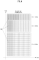
- FIG. 3 illustrates a resource grid in a wireless communication system to which the present disclosure may be applied.
- a resource grid is configured with N RB ⁇ N sc RB subcarriers in a frequency domain and one subframe is configured with 14 ⁇ 2 ⁇ OFDM symbols, but it is not limited thereto.
- a transmitted signal is described by OFDM symbols of 2 ⁇ N symb ( ⁇ ) ) and one or more resource grids configured with N RB ⁇ N sc RB subcarriers.
- N RB ⁇ ⁇ N RB max, ⁇ The N RB max, ⁇ represents a maximum transmission bandwidth, which may be different between an uplink and a downlink as well as between numerologies.
- one resource grid may be configured per ⁇ and antenna port p.
- Each element of a resource grid for ⁇ and an antenna port p is referred to as a resource element and is uniquely identified by an index pair (k,l').
- an index pair (k,l) is used.
- l 0,...,N symb ⁇ -1.
- a resource element (k,l') for ⁇ and an antenna port p corresponds to a complex value, a k , l' (p, ⁇ ) .
- indexes p and ⁇ may be dropped, whereupon a complex value may be a k,l' (p) or a k,l' .
- Point A plays a role as a common reference point of a resource block grid and is obtained as follows.
- offsetToPointA for a primary cell (PCell) downlink represents a frequency offset between point A and the lowest subcarrier of the lowest resource block overlapped with a SS/PBCH block which is used by a terminal for an initial cell selection. It is expressed in resource block units assuming a 15kHz subcarrier spacing for FR1 and a 60kHz subcarrier spacing for FR2.
- absoluteFrequencyPointA represents a frequency-position of point A expressed as in ARFCN (absolute radio-frequency channel number).
- Common resource blocks are numbered from 0 to the top in a frequency domain for a subcarrier spacing configuration ⁇ .
- the center of subcarrier 0 of common resource block 0 for a subcarrier spacing configuration ⁇ is identical to 'point A'.
- a relationship between a common resource block numbern CRB ⁇ and a resource element (k,l) for a subcarrier spacing configuration ⁇ in a frequency domain is given as in the following Equation 1.
- n CRB ⁇ ⁇ k N sc RB ⁇
- Physical resource blocks are numbered from 0 to N BWP,i size, ⁇ -1 in a bandwidth part (BWP) and i is a number of a BWP.
- a relationship between a physical resource block n PRB and a common resource block n CRB in BWP i is given by the following Equation 2.
- N BWP,i start, ⁇ is a common resource block that a BWP starts relatively to common resource block 0.
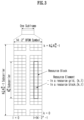
- FIG. 4 illustrates a physical resource block in a wireless communication system to which the present disclosure may be applied.
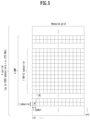
- FIG. 5 illustrates a slot structure in a wireless communication system to which the present disclosure may be applied.
- a slot includes a plurality of symbols in a time domain. For example, for a normal CP, one slot includes 7 symbols, but for an extended CP, one slot includes 6 symbols.
- a carrier includes a plurality of subcarriers in a frequency domain.
- An RB Resource Block
- a BWP(Bandwidth Part) is defined as a plurality of consecutive (physical) resource blocks in a frequency domain and may correspond to one numerology (e.g., an SCS, a CP length, etc.).
- a carrier may include a maximum N (e.g., 5) BWPs.
- a data communication may be performed through an activated BWP and only one BWP may be activated for one terminal.
- each element is referred to as a resource element (RE) and one complex symbol may be mapped.
- RE resource element
- a terminal operating in such a wideband CC may always operate turning on a radio frequency (FR) chip for the whole CC, terminal battery consumption may increase.
- FR radio frequency
- a different numerology e.g., a subcarrier spacing, etc.
- each terminal may have a different capability for the maximum bandwidth.
- a base station may indicate a terminal to operate only in a partial bandwidth, not in a full bandwidth of a wideband CC, and a corresponding partial bandwidth is defined as a bandwidth part (BWP) for convenience.
- a BWP may be configured with consecutive RBs on a frequency axis and may correspond to one numerology (e.g., a subcarrier spacing, a CP length, a slot/a mini-slot duration).
- a base station may configure a plurality of BWPs even in one CC configured to a terminal. For example, a BWP occupying a relatively small frequency domain may be configured in a PDCCH monitoring slot, and a PDSCH indicated by a PDCCH may be scheduled in a greater BWP.
- a base station may configure at least one DL/UL BWP to a terminal associated with a wideband CC.
- a base station may activate at least one DL/UL BWP of configured DL/UL BWP(s) at a specific time (by L1 signaling or MAC CE(Control Element) or RRC signaling, etc.).
- a base station may indicate switching to other configured DL/UL BWP (by L1 signaling or MAC CE or RRC signaling, etc.).
- a timer when a timer value is expired, it may be switched to a determined DL/UL BWP.
- an activated DL/UL BWP is defined as an active DL/UL BWP.
- a configuration on a DL/UL BWP may not be received when a terminal performs an initial access procedure or before a RRC connection is set up, so a DL/UL BWP which is assumed by a terminal under these situations is defined as an initial active DL/UL BWP.
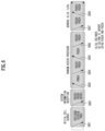
- FIG. 6 illustrates physical channels used in a wireless communication system to which the present disclosure may be applied and a general signal transmission and reception method using them.
- a terminal receives information through a downlink from a base station and transmits information through an uplink to a base station.
- Information transmitted and received by a base station and a terminal includes data and a variety of control information and a variety of physical channels exist according to a type/a usage of information transmitted and received by them.
- a terminal When a terminal is turned on or newly enters a cell, it performs an initial cell search including synchronization with a base station or the like (S601).
- a terminal may synchronize with a base station by receiving a primary synchronization signal (PSS) and a secondary synchronization signal (SSS) from a base station and obtain information such as a cell identifier (ID), etc.
- PSS primary synchronization signal
- SSS secondary synchronization signal
- ID cell identifier
- a terminal may obtain broadcasting information in a cell by receiving a physical broadcast channel (PBCH) from a base station.
- PBCH physical broadcast channel
- a terminal may check out a downlink channel state by receiving a downlink reference signal (DL RS) at an initial cell search stage.
- DL RS downlink reference signal
- a terminal which completed an initial cell search may obtain more detailed system information by receiving a physical downlink control channel (PDCCH) and a physical downlink shared channel (PDSCH) according to information carried in the PDCCH (S602).
- PDCCH physical downlink control channel
- PDSCH physical downlink shared channel
- a terminal when a terminal accesses to a base station for the first time or does not have a radio resource for signal transmission, it may perform a random access (RACH) procedure to a base station (S603 to S606).
- RACH random access
- a terminal may transmit a specific sequence as a preamble through a physical random access channel (PRACH) (S603 and S605) and may receive a response message for a preamble through a PDCCH and a corresponding PDSCH (S604 and S606).
- PRACH physical random access channel
- a contention based RACH may additionally perform a contention resolution procedure.
- a terminal which performed the above-described procedure subsequently may perform PDCCH/PDSCH reception (S607) and PUSCH(Physical Uplink Shared Channel)/PUCCH(physical uplink control channel) transmission (S608) as a general uplink/downlink signal transmission procedure.
- a terminal receives downlink control information (DCI) through a PDCCH.
- DCI includes control information such as resource allocation information for a terminal and a format varies depending on its purpose of use.
- control information which is transmitted by a terminal to a base station through an uplink or is received by a terminal from a base station includes a downlink/uplink ACK/NACK(Acknowledgement/Non-Acknowledgement) signal, a CQI(Channel Quality Indicator), a PMI(Precoding Matrix Indicator), a RI(Rank Indicator), etc.
- a terminal may transmit control information of the above-described CQI/PMI/RI, etc. through a PUSCH and/or a PUCCH.
- Table 5 represents an example of a DCI format in an NR system.
- DCI Format Use 0_0 Scheduling of a PUSCH in one cell 0_1 Scheduling of one or multiple PUSCHs in one cell, or indication of cell group downlink feedback information to a UE 0_2 Scheduling of a PUSCH in one cell 1_0 Scheduling of a PDSCH in one DL cell 1_1 Scheduling of a PDSCH in one cell 1_2 Scheduling of a PDSCH in one cell
- DCI formats 0_0, 0_1 and 0_2 may include resource information (e.g., UL/SUL(Supplementary UL), frequency resource allocation, time resource allocation, frequency hopping, etc.), information related to a transport block(TB) (e.g., MCS(Modulation Coding and Scheme), a NDI(New Data Indicator), a RV(Redundancy Version), etc.), information related to a HARQ(Hybrid - Automatic Repeat and request) (e.g., a process number, a DAI(Downlink Assignment Index), PDSCH-HARQ feedback timing, etc.), information related to multiple antennas (e.g., DMRS sequence initialization information, an antenna port, a CSI request, etc.), power control information (e.g., PUSCH power control, etc.) related to scheduling of a PUSCH and control information included in each DCI format may be pre-defined.
- resource information e.g., UL/SUL(Sup
- DCI format 0_1 is used to indicate scheduling of one or more PUSCHs or configure grant (CG) downlink feedback information to a terminal in one cell.
- Information included in DCI format 0_1 is CRC scrambled by a C-RNTI or a CS-RNTI or a SP-CSI-RNTI (Semi-Persistent CSI RNTI) or a MCS-C-RNTI and transmitted.
- DCI format 0_2 is used for scheduling of a PUSCH in one cell.
- Information included in DCI format 0_2 is CRC scrambled by a C-RNTI or a CS-RNTI or a SP-CSI-RNTI or a MCS-C-RNTI and transmitted.
- DCI formats 1_0, 1_1 and 1_2 may include resource information (e.g., frequency resource allocation, time resource allocation, VRB(virtual resource block)-PRB(physical resource block) mapping, etc.), information related to a transport block(TB)(e.g., MCS, NDI, RV, etc.), information related to a HARQ (e.g., a process number, DAI, PDSCH-HARQ feedback timing, etc.), information related to multiple antennas (e.g., an antenna port, a TCI(transmission configuration indicator), a SRS(sounding reference signal) request, etc.), information related to a PUCCH (e.g., PUCCH power control, a PUCCH resource indicator, etc.) related to scheduling of a PDSCH and control information included in each DCI format may be pre-defined.
- resource information e.g., frequency resource allocation, time resource allocation, VRB(virtual resource block)-PRB(physical resource block) mapping, etc.
- DCI format 1_0 is used for scheduling of a PDSCH in one DL cell.
- Information included in DCI format 1_0 is CRC scrambled by a C-RNTI or a CS-RNTI or a MCS-C-RNTI and transmitted.
- DCI format 1_2 is used for scheduling of a PDSCH in one cell.
- Information included in DCI format 1_2 is CRC scrambled by a C-RNTI or a CS-RNTI or a MCS-C-RNTI and transmitted.
- a coordinated multi point (CoMP) scheme refers to a scheme in which a plurality of base stations effectively control interference by exchanging (e.g., using an X2 interface) or utilizing channel information (e.g., RI/CQI/PMI/LI(layer indicator), etc.) fed back by a terminal and cooperatively transmitting to a terminal.
- a CoMP may be classified into joint transmission(JT), coordinated Scheduling(CS), coordinated Beamforming(CB), dynamic Point Selection(DPS), dynamic Point Blocking(DPB), etc.
- M-TRP transmission schemes that M TRPs transmit data to one terminal may be largely classified into i) eMBB M-TRP transmission, a scheme for improving a transfer rate, and ii) URLLC M-TRP transmission, a scheme for increasing a reception success rate and reducing latency.
- M-TRP transmission schemes may be classified into i) M-TRP transmission based on M-DCI(multiple DCI) that each TRP transmits different DCIs and ii) M-TRP transmission based on S-DCI(single DCI) that one TRP transmits DCI.
- M-DCI based M-TRP transmission all scheduling information on data transmitted by M TRPs should be delivered to a terminal through one DCI, it may be used in an environment of an ideal BackHaul (ideal BH) where dynamic cooperation between two TRPs is possible.
- scheme 3/4 is under discussion for standardization.
- scheme 4 means a scheme in which one TRP transmits a transport block(TB) in one slot and it has an effect to improve a probability of data reception through the same TB received from multiple TRPs in multiple slots.
- scheme 3 means a scheme in which one TRP transmits a TB through consecutive number of OFDM symbols (i.e., a symbol group) and TRPs may be configured to transmit the same TB through a different symbol group in one slot.
- UE may recognize PUSCH (or PUCCH) scheduled by DCI received in different control resource sets(CORESETs)(or CORESETs belonging to different CORESET groups) as PUSCH (or PUCCH) transmitted to different TRPs or may recognize PDSCH (or PDCCH) from different TRPs.
- the below-described method for UL transmission e.g., PUSCH/PUCCH
- PUSCH/PUCCH PUSCH/PUCCH
- MTRP-URLLC may mean that a M TRPs transmit the same transport block(TB) by using different layer/time/frequency.
- a UE configured with a MTRP-URLLC transmission scheme receives an indication on multiple TCI state(s) through DCI and may assume that data received by using a QCL RS of each TCI state are the same TB.
- MTRP-eMBB may mean that M TRPs transmit different TBs by using different layer/time/frequency.
- a UE configured with a MTRP-eMBB transmission scheme receives an indication on multiple TCI state(s) through DCI and may assume that data received by using a QCL RS of each TCI state are different TBs.
- UE may decide/determine whether the corresponding M-TRP transmission is URLLC transmission or eMBB transmission.
- CRC masking of DCI received by UE is performed by using a RNTI configured for MTRP-URLLC, it may correspond to URLLC transmission
- CRC masking of DCI is performed by using a RNTI configured for MTRP-eMBB, it may correspond to eMBB transmission.
- a CORESET group ID described/mentioned in the present disclosure may mean an index/identification information (e.g., an ID, etc.) for distinguishing a CORESET for each TRP/panel.
- a CORESET group may be a group/union of CORESET distinguished by an index/identification information (e.g., an ID)/the CORESET group ID, etc. for distinguishing a CORESET for each TRP/panel.
- a CORESET group ID may be specific index information defined in a CORESET configuration.
- a CORESET group may be configured/indicated/defined by an index defined in a CORESET configuration for each CORESET.
- a CORESET group ID may mean an index/identification information/an indicator, etc. for distinguishment/identification between CORESETs configured/associated with each TRP/panel.
- a CORESET group ID described/mentioned in the present disclosure may be expressed by being substituted with a specific index/specific identification information/a specific indicator for distinguishment/identification between CORESETs configured/associated with each TRP/panel.
- the CORESET group ID i.e., a specific index/specific identification information/a specific indicator for distinguishment/identification between CORESETs configured/associated with each TRP/panel may be configured/indicated to a terminal through higher layer signaling (e.g., RRC signaling)/L2 signaling (e.g., MAC-CE)/L1 signaling (e.g., DCI), etc.
- RRC signaling e.g., RRC signaling
- L2 signaling e.g., MAC-CE
- L1 signaling e.g., DCI
- uplink control information e.g., CSI, HARQ-A/N(ACK/NACK), SR(scheduling request)
- uplink physical channel resources e.g., PUCCH/PRACH/SRS resources
- HARQ A/N(process/retransmission) for PDSCH/PUSCH, etc. scheduled per each TRP/panel may be managed per corresponding CORESET group (i.e., per TRP/panel belonging to the same CORESET group).
- ControlResourceSet information element is used to configure a time/frequency control resource set (CORESET).
- the control resource set (CORESET) may be related to detection and reception of downlink control information.
- the ControlResourceSet IE may include a CORESET-related ID (e.g., controlResourceSetID)/an index of a CORESET pool for a CORESET (e.g., CORESETPoolIndex)/a time/frequency resource configuration of a CORESET/TCI information related to a CORESET, etc.
- an index of a CORESET pool (e.g., CORESETPoolIndex) may be configured as 0 or 1.
- a CORESET group may correspond to a CORESET pool and a CORESET group ID may correspond to a CORESET pool index (e.g., CORESETPoolIndex).
- NCJT Non-coherent joint transmission
- TP transmission points
- DMRS Demodulation Multiplexing Reference Signal
- a TP delivers data scheduling information through DCI to a terminal receiving NCJT.
- a scheme in which each TP participating in NCJT delivers scheduling information on data transmitted by itself through DCI is referred to as 'multi DCI based NCJT'.
- UE receives N DCI and N PDSCHs from N TPs.
- a scheme in which one representative TP delivers scheduling information on data transmitted by itself and data transmitted by a different TP (i.e., a TP participating in NCJT) through one DCI is referred to as 'single DCI based NCJT'.
- N TPs transmit one PDSCH, but each TP transmits only some layers of multiple layers included in one PDSCH. For example, when 4-layer data is transmitted, TP 1 may transmit 2 layers and TP 2 may transmit 2 remaining layers to UE.
- NCJT partially overlapped NCJT
- NCJT may be classified into fully overlapped NCJT that time frequency resources transmitted by each TP are fully overlapped and partially overlapped NCJT that only some time frequency resources are overlapped.
- data of both of TP 1 and TP 2 are transmitted in some time frequency resources and data of only one TP of TP 1 or TP 2 is transmitted in remaining time frequency resources.
- FIG. 7 illustrates a method of multiple TRPs transmission in a wireless communication system to which the present disclosure may be applied.
- a layer group may mean a predetermined layer set including one or more layers.
- the amount of transmitted resources increases due to the number of a plurality of layers and thereby a robust channel coding with a low coding rate may be used for a TB, and additionally, because a plurality of TRPs have different channels, it may be expected to improve reliability of a received signal based on a diversity gain.
- FIG. 15(b) an example that different CWs are transmitted through layer groups corresponding to different TRPs is shown.
- a TB corresponding to CW #1 and CW #2 in the drawing is identical to each other.
- CW #1 and CW #2 mean that the same TB is respectively transformed through channel coding, etc. into different CWs by different TRPs. Accordingly, it may be considered as an example that the same TB is repetitively transmitted.
- FIG. 15(b) it may have a disadvantage that a code rate corresponding to a TB is higher compared to FIG. 15(a).
- it has an advantage that it may adjust a code rate by indicating a different RV (redundancy version) value or may adjust a modulation order of each CW for encoded bits generated from the same TB according to a channel environment.
- RV redundancy version
- probability of data reception of a terminal may be improved as the same TB is repetitively transmitted through a different layer group and each layer group is transmitted by a different TRP/panel. It is referred to as a SDM (Spatial Division Multiplexing) based M-TRP URLLC transmission method. Layers belonging to different layer groups are respectively transmitted through DMRS ports belonging to different DMRS CDM groups.
- the above-described contents related to multiple TRPs are described based on an SDM (spatial division multiplexing) method using different layers, but it may be naturally extended and applied to a FDM (frequency division multiplexing) method based on a different frequency domain resource (e.g., RB/PRB (set), etc.) and/or a TDM (time division multiplexing) method based on a different time domain resource (e.g., a slot, a symbol, a sub-symbol, etc.).
- FDM frequency division multiplexing
- a different frequency domain resource e.g., RB/PRB (set), etc.
- TDM time division multiplexing
- FIG. 8 is a diagram illustrating a downlink transmission and reception operation in a wireless communication system to which the present disclosure can be applied.
- a base station schedules downlink transmission such as a frequency/time resource, a transport layer, a downlink precoder, an MCS, etc. (S1401).
- a base station can determine a beam for PDSCH transmission to a UE through the operations described above.
- a UE receives DCI for downlink scheduling (i.e., including scheduling information of a PDSCH) from a base station on a PDCCH (S1402).
- DCI for downlink scheduling i.e., including scheduling information of a PDSCH
- DCI format 1_0, 1_1, or 1_2 may be used for downlink scheduling, and in particular, DCI format 1_1 includes the following information: an identifier for a DCI format, a bandwidth part indicator, a frequency domain resource assignment, a time domain resource assignment, a PRB bundling size indicator, a rate matching indicator, a ZP CSI-RS trigger, antenna port(s), a transmission configuration indication (TCI), an SRS request, a DMRS (Demodulation Reference Signal) sequence initialization
- a number of DMRS ports may be scheduled according to each state indicated in an antenna port(s) field, and also single-user (SU)/multi-user (MU) user transmission scheduling is possible.
- SU single-user
- MU multi-user
- a TCI field is composed of 3 bits, and a QCL for a DMRS is dynamically indicated by indicating up to 8 TCI states according to a TCI field value.
- a UE receives downlink data from a base station on a PDSCH (S1403).
- a UE When a UE detects a PDCCH including DCI formats 1_0, 1_1, and 1_2, it decodes a PDSCH according to indications by corresponding DCI.
- a DMRS configuration type may be configured for the UE by a higher layer parameter 'dmrs-Type', and a DMRS type is used to receive a PDSCH.
- a maximum number of front-loaded DMRA symbols for the PDSCH may be configured for a terminal by a higher layer parameter 'maxLength'.
- DMRS configuration type 1 For DMRS configuration type 1, if a single codeword is scheduled for a UE and an antenna port mapped to an index of ⁇ 2, 9, 10, 11 or 30 ⁇ is indicated or if a single codeword is scheduled and an antenna port mapped to an index of ⁇ 2, 9, 10, 11 or 12 ⁇ or ⁇ 2, 9, 10, 11, 30 or 31 ⁇ is indicated, or if two codewords are scheduled, the UE assumes that all remaining orthogonal antenna ports are not associated with PDSCH transmission to another UE.
- DMRS configuration type 1 if a single codeword is scheduled for a UE and an antenna port mapped to an index of ⁇ 2, 10 or 23 ⁇ is indicated, or if a single codeword is scheduled and an antenna port mapped to an index of ⁇ 2, 10, 23 or 24 ⁇ or ⁇ 2, 10, 23 or 58 ⁇ is indicated, or if two codewords are scheduled for a UE, the UE assumes that all remaining orthogonal antenna ports are not associated with PDSCH transmission to another UE.
- a precoding unit (precoding granularity) P' may be assumed to be a contiguous resource block in a frequency domain.
- P' may correspond to one of ⁇ 2, 4, wideband ⁇ .
- P' is determined to be wideband, a UE does not expect to be scheduled with non-contiguous PRBs, and a UE can assume that the same precoding is applied to allocated resources.
- a precoding resource block group PRG is divided into P' consecutive PRBs.
- An actual number of consecutive PRBs in each PRG may be one or more.
- a UE may assume that the same precoding is applied to consecutive downlink PRBs within a PRG.
- the UE In order for a UE to determine a modulation order, a target code rate, and a transport block size in a PDSCH, the UE first reads a 5-bit MCD field in DCI and determines a modulation order and a target code rate. Then, the UE reads a redundancy version field in the DCI and determines a redundancy version. Then, a UE determines a transport block size using a number of layers and a total number of allocated PRBs before rate matching.
- FIG. 9 is a diagram illustrating an uplink transmission and reception operation in a wireless communication system to which the present disclosure can be applied.
- a base station schedules uplink transmission such as a frequency/time resource, a transport layer, an uplink precoder, an MCS, etc. (S1501).
- a base station can determine a beam for PUSCH transmission to a UE through the operations described above.
- a UE receives DCI for uplink scheduling (i.e., including scheduling information of a PUSCH) from a base station on a PDCCH (S1502).
- DCI format 0_0, 0_1, or 0_2 may be used for uplink scheduling, and in particular, DCI format 0_1 includes the following information: an identifier for a DCI format, a UL/SUL (supplementary uplink) indicator, a bandwidth part indicator, a frequency domain resource assignment, a time domain resource assignment, a frequency hopping flag, a modulation and coding scheme (MCS), an SRS resource indicator (SRI), precoding information and number of layers, antenna port(s), an SRS request, a DMRS sequence initialization, a UL-SCH (Uplink Shared Channel) indicator
- MCS modulation and coding scheme
- SRI SRS resource indicator
- SRS resources configured in an SRS resource set associated with the higher upper layer parameter 'usage' may be indicated by an SRS resource indicator field.
- the 'spatialRelationInfo' can be configured for each SRS resource, and its value can be one of ⁇ CRI, SSB, SRI ⁇ .
- a UE transmits uplink data to a base station on a PUSCH (S1503).
- a UE When a UE detects a PDCCH including DCI formats 0_0, 0_1, and 0_2, it transmits a PUSCH according to indications by corresponding DCI.
- codebook-based transmission Two transmission methods are supported for PUSCH transmission: codebook-based transmission and non-codebook-based transmission:
- a CSI-RS channel state information-reference signal
- L1(layer 1)-RSRP reference signal received power
- mobility L1(layer 1)-RSRP(reference signal received power) computation
- CSI computation is related to CSI acquisition and L1-RSRP computation is related to beam management (BM).
- CSI(channel state information) collectively refers to information which may represent quality of a radio channel (or also referred to as a link) formed between a terminal and an antenna port.
- a terminal e.g., user equipment, UE receives configuration information related to CSI from a base station (e.g., general Node B, gNB) through RRC(radio resource control) signaling.
- a base station e.g., general Node B, gNB
- RRC radio resource control
- the configuration information related to CSI may include at least one of information related to a CSI-IM (interference management) resource, information related to CSI measurement configuration, information related to CSI resource configuration, information related to a CSI-RS resource or information related to CSI report configuration.
- CSI-IM interference management
- Information related to a CSI-IM resource may include CSI-IM resource information, CSI-IM resource set information, etc.
- a CSI-IM resource set is identified by a CSI-IM resource set ID (identifier) and one resource set includes at least one CSI-IM resource.
- Each CSI-IM resource is identified by a CSI-IM resource ID.
- Information related to CSI resource configuration may be expressed as CSI-ResourceConfig IE.
- Information related to a CSI resource configuration defines a group which includes at least one of an NZP(non zero power) CSI-RS resource set, a CSI-IM resource set or a CSI-SSB resource set.
- the information related to a CSI resource configuration may include a CSI-RS resource set list and the CSI-RS resource set list may include at least one of a NZP CSI-RS resource set list, a CSI-IM resource set list or a CSI-SSB resource set list.
- a CSI-RS resource set is identified by a CSI-RS resource set ID and one resource set includes at least one CSI-RS resource.
- Each CSI-RS resource is identified by a CSI-RS resource ID.
- Parameters representing a usage of a CSI-RS may be configured per NZP CSI-RS resource set.
- Information related to a CSI report configuration includes a report configuration type (reportConfigType) parameter representing a time domain behavior and a report quantity (reportQuantity) parameter representing CSI-related quantity for a report.
- the time domain behavior may be periodic, aperiodic or semi-persistent.
- a terminal measures CSI based on the configuration information related to CSI.
- the CSI measurement may include (1) a process in which a terminal receives a CSI-RS and (2) a process in which CSI is computed through a received CSI-RS and detailed description thereon is described after.
- RE(resource element) mapping of a CSI-RS resource in a time and frequency domain is configured by higher layer parameter CSI-RS-ResourceMapping.
- a terminal reports the measured CSI to a base station.
- the terminal may omit the report. But, although the quantity is configured as 'none (or No report)', the terminal may perform a report to a base station.
- the quantity is configured as 'none', an aperiodic TRS is triggered or repetition is configured. In this case, only when repetition is configured as 'ON', a report of the terminal may be omitted.
- node(s) and UE(s) in a wireless communication network are becoming more intelligent/advanced.
- various network/base station decision parameter values e.g., transmission/reception power of each base station, transmission power of each UE, precoder/beam of base station/UE, time/frequency resource allocation for each UE, duplex method of each base station, etc.
- environmental parameters e.g., distribution/location of base stations, distribution/location/material of buildings/furniture, etc., location/movement direction/speed of UEs, climate information, etc.
- FIG. 10 illustrates a classification of artificial intelligence.
- AI artificial intelligence
- Machine Learning refers to a technology in which machines learn patterns for decision-making from data on their own without explicitly programming rules.
- Deep Learning is an artificial neural network-based model that allows a machine to perform feature extraction and decision from unstructured data at once.
- the algorithm relies on a multilayer network of interconnected nodes for feature extraction and transformation, inspired by the biological nervous system, or Neural Network.
- Common deep learning network architectures include deep neural networks (DNNs), recurrent neural networks (RNNs), and convolutional neural networks (CNNs).
- AI can be narrowly referred to as artificial intelligence based on deep learning, but is not limited to this in the present disclosure. That is, in the present disclosure, AI (or AI/ML) may collectively refer to automation technologies applied to intelligent machines (e.g., UE, RAN, network nodes, etc.) that can perform tasks like humans.
- intelligent machines e.g., UE, RAN, network nodes, etc.
- AI (or AI/ML) can be classified according to various criteria as follows.
- Offline learning follows a sequential procedure of database collection, learning, and prediction.
- collection and learning can be performed offline, and the completed program can be installed in the field and used for prediction work.
- the system does not learn incrementally, the learning is performed using all available collected data and applied to the system without further learning. If learning about new data is necessary, learning can begin again using all new data.
- centralized learning training data collected from a plurality of different nodes is reported to a centralized node, all data resources/storage/learning (e.g., supervised learning, unsupervised learning, reinforcement learning, etc.) are performed in one centralized node.
- all data resources/storage/learning e.g., supervised learning, unsupervised learning, reinforcement learning, etc.
- Federated learning is a collective model built on data that exists across distributed data owners. Instead of collecting data into a model, AI/ML models are imported into a data source, allowing local nodes/individual devices to collect data and train their own copies of the model, eliminating the need to report the source data to a central node. In federated learning, the parameters/weights of an AI/ML model can be sent back to the centralized node to support general model training. Federated learning has advantages in terms of increased computation speed and information security. In other words, the process of uploading personal data to the central server is unnecessary, preventing leakage and misuse of personal information.
- Distributed learning refers to the concept in which machine learning processes are scaled and distributed across a cluster of nodes. Training models are split and shared across multiple nodes operating simultaneously to speed up model training.
- Supervised learning is a machine learning task that aims to learn a mapping function from input to output, given a labeled data set.
- the input data is called training data and has known labels or results.
- An example of supervised learning is as follows.
- Supervised learning can be further grouped into regression and classification problems, where classification is predicting a label and regression is predicting a quantity.
- Unsupervised learning is a machine learning task that aims to learn features that describe hidden structures in unlabeled data. The input data is not labeled and there are no known results.
- Some examples of unsupervised learning include K-means clustering, Principal Component Analysis (PCA), nonlinear Independent Component Analysis (ICA), and Long-Short-Term Memory (LSTM).
- RL reinforcement learning
- the agent aims to optimize long-term goals by interacting with the environment based on a trial and error process, and is goal-oriented learning based on interaction with the environment.
- An example of the RL algorithm is as follows.
- reinforcement learning can be grouped into model-based reinforcement learning and model-free reinforcement learning as follows.
- RL algorithm can also be classified into valuebased RL vs. policy-based RL, policy-based RL vs. non-policy RL, etc.
- FIG. 11 illustrates a feed-forward neural network
- a feed-forward neural network is composed of an input layer, a hidden layer, and an output layer.
- FFNN In FFNN, information is transmitted only from the input layer to the output layer, and if there is a hidden layer, it passes through it.
- Category 1, Category 2, and Category 3 may be considered in terms of training, and Category 1 and Category 2 may be considered in terms of inference.
- FIG. 12 illustrates a recurrent neural network
- LSTM Long Short-Term Memory
- LSTM Long Short-Term Memory
- FIG. 13 illustrates a convolutional neural network
- CNN Convolutional neural network
- Category 1, Category 2, and Category 3 may be considered in terms of training, and Category 1 and Category 2 may be considered in terms of inference.
- FIG. 14 illustrates an auto encoder
- Auto encoder refers to a neural network that receives a feature vector x (x 1 , x 2 , x 3 , ...) as input and outputs the same or similar vector x' (x' 1 , x' 2 , x' 3 , ...)'.
- Auto encoder has the same characteristics as the input node and output node. Since the auto encoder reconstructs the input, the output can be referred to as reconstruction. Additionally, auto encoder is a type of unsupervised learning.
- the loss function of the auto encoder illustrated in FIG. 14 is calculated based on the difference between input and output, and based on this, the degree of input loss is identified and an optimization process is performed in the auto encoder to minimize the loss.
- AI or AI/ML
- AI/ML Training An online or offline process to train an AI model by learning features and patterns that best present data and get the trained AI/ML model for inference.
- AI/ML Inference A process of using a trained AI/ML model to make a prediction or guide the decision based on collected data and AI/ML model.
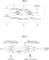
- FIG. 15 illustrates a functional framework for an AI operation.
- Examples of input data may include measurements from UEs or different network entities, feedback from Actor, output from an AI model.
- the Data Collection function (10) performs data preparation based on input data and provides input data processed through data preparation.
- the Data Collection function (10) does not perform specific data preparation (e.g., data pre-processing and cleaning, formatting and transformation) for each AI algorithm, and data preparation common to AI algorithms can be performed.
- the Model Training function (10) After performing the data preparation process, the Model Training function (10) provides Training Data (11) to the Model Training function (20) and provides Inference Data (12) to the Model Inference function (30).
- Training Data (11) is data required as input for the AI Model Training function (20).
- Inference Data (12) is data required as input for the AI Model Inference function (30).
- the Data Collection function (10) may be performed by a single entity (e.g., UE, RAN node, network node, etc.), but may also be performed by a plurality of entities.
- Training Data (11) and Inference Data (12) can be provided from a plurality of entities to the Model Training function (20) and the Model Inference function (30), respectively.
- Model Training function (20) is a function that performs the AI model training, validation, and testing which may generate model performance metrics as part of the model testing procedure.
- the Model Training function (20) is also responsible for data preparation (e.g., data pre-processing and cleaning, formatting, and transformation) based on Training Data (11) delivered by a Data Collection function (10), if required.
- Model Deployment/Update (13) is used to initially deploy a trained, validated, and tested AI model to the Model Inference function (30) or to deliver an updated model to the Model Inference function (30).
- Model Inference function (30) is a function that provides AI model inference output (16) (e.g., predictions or decisions). Model Inference function (30) may provide Model Performance Feedback (14) to Model Training function (20) when applicable. The Model Inference function (30) is also responsible for data preparation (e.g., data pre-processing and cleaning, formatting, and transformation) based on Inference Data (12) delivered by a Data Collection function (10), if required.
- Output (16) refers to the inference output of the AI model produced by a Model Inference function (30), and details of inference output may be use case specific.
- Model Performance Feedback (14) may be used for monitoring the performance of the AI model, when available, and this feedback may be omitted.
- Actor function (40) is a function that receives the Output (16) from the Model Inference function (30) and triggers or performs corresponding actions.
- the Actor function (40) may trigger actions directed to other entities (e.g., one or more UEs, one or more RAN nodes, one or more network nodes, etc) or to itself.
- Feedback (15) may be used to derive Training data (11), Inference data (12) or to monitor the performance of the AI Model and its impact to the network, etc.
- training data and validation data can be divided into 8:2 or 7:3, and if testing is included, 6:2:2 (training: validation: test) can be used.
- a cooperation level can be defined as follows, and modifications can be made by combining the following multiple levels or separating any one level.
- Cat 1 This involves inter-node support to improve the AI/ML algorithm of each node. This applies if a UE receives support from a gNB (for training, adaptation, etc.) and vice versa. At this level, model exchange between network nodes is not required.
- a RAN node e.g., base station, TRP, base station central unit (CU), etc.
- a network node e.g., a network operator's operation administration maintenance (OAM), or a UE.
- OAM network operator's operation administration maintenance
- the function illustrated in FIG. 15 may be implemented through cooperation of two or more entities among a RAN, a network node, an CAM of network operator, or a UE.
- one entity may perform some of the functions of FIG. 15 and other entities may perform the remaining functions.
- transmission/provision of data/information between each function may be omitted.
- the Model Training function (20) and the Model Inference function (30) are performed by the same entity, the delivery/provision of Model Deployment/Update (13) and Model Performance Feedback (14) can be omitted.
- any one of the functions illustrated in FIG. 15 may be performed through collaboration between two or more entities among a RAN, a network node, an OAM of a network operator, or a UE. This can be referred to as a split AI operation.
- FIG. 16 is a diagram illustrating split AI inference.
- FIG. 16 illustrates a case in which, among split AI operations, the Model Inference function is performed in cooperation with an end device such as a UE and a network AI/ML endpoint.
- Model Training function In addition to the Model Inference function, the Model Training function, the Actor, and the Data Collection function are respectively split into multiple parts depending on the current task and environment, and can be performed by multiple entities collaborating.
- computation-intensive and energy-intensive parts may be performed at a network endpoint, while parts sensitive to personal information and delay-sensitive parts may be performed at an end device.
- an end device can execute a task/model from input data to a specific part/layer and then transmit intermediate data to a network endpoint.
- a network endpoint executes the remaining parts/layers and provides inference outputs to one or more devices that perform an action/task.
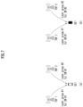
- FIG. 17 illustrates an application of a functional framework in a wireless communication system.
- FIG. 7 illustrates a case where the AI Model Training function is performed by a network node (e.g., core network node, network operator's OAM, etc.) and the AI Model Inference function is performed by a RAN node (e.g., base station, TRP, CU of base station, etc.).
- a network node e.g., core network node, network operator's OAM, etc.
- the AI Model Inference function is performed by a RAN node (e.g., base station, TRP, CU of base station, etc.).
- Step 1 RAN Node 1 and RAN Node 2 transmit input data (i.e., Training data) for AI Model Training to the network node.
- RAN Node 1 and RAN Node 2 may transmit the data collected from the UE (e.g., UE measurements related to RSRP, RSRQ, SINR of the serving cell and neighboring cells, UE location, speed, etc.) to the network node.
- the UE e.g., UE measurements related to RSRP, RSRQ, SINR of the serving cell and neighboring cells, UE location, speed, etc.
- Step 2 The network node trains the AI Model using the received training data.
- Step 3 The network node distributes/updates the AI Model to RAN Node 1 and/or RAN Node 2.
- RAN Node 1 (and/or RAN Node 2) may continue to perform model training based on the received AI Model.
- Step 4 RAN Node 1 receives input data (i.e., Inference data) for AI Model Inference from the UE and RAN Node 2.
- input data i.e., Inference data
- Step 5 RAN Node 1 performs AI Model Inference using the received Inference data to generate output data (e.g., prediction or decision).
- output data e.g., prediction or decision
- Step 6 If applicable, RAN Node 1 may send model performance feedback to the network node.
- Step 7 RAN Node 1, RAN Node 2, and UE (or 'RAN Node 1 and UE', or 'RAN Node 1 and RAN Node 2') perform an action based on the output data. For example, in the case of load balancing operation, the UE may move from RAN node 1 to RAN node 2.
- Step 8 RAN Node 1 and RAN Node 2 transmit feedback information to the network node.
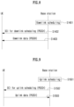
- FIG. 18 illustrates an application of a functional framework in a wireless communication system.
- FIG. 18 illustrates a case where both the AI Model Training function and the AI Model Inference function are performed by a RAN node (e.g., base station, TRP, CU of the base station, etc.).
- a RAN node e.g., base station, TRP, CU of the base station, etc.
- Step 1 The UE and RAN Node 2 transmit input data (i.e., Training data) for AI Model Training to RAN Node 1.
- input data i.e., Training data
- Step 2 RAN Node 1 trains the AI Model using the received training data.
- Step 3 RAN Node 1 receives input data (i.e., Inference data) for AI Model Inference from the UE and RAN Node 2.
- input data i.e., Inference data
- Step 5 RAN Node 1, RAN Node 2, and the UE (or 'RAN Node 1 and UE', or 'RAN Node 1 and RAN Node 2') perform an action based on the output data. For example, in the case of load balancing operation, the UE may move from RAN node 1 to RAN node 2.
- Step 6 RAN node 2 transmits feedback information to RAN node 1.
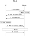
- FIG. 19 illustrates an application of a functional framework in a wireless communication system.
- FIG. 19 illustrates a case where the AI Model Training function is performed by a RAN node (e.g., base station, TRP, CU of the base station, etc.), and the AI Model Inference function is performed by the UE.
- a RAN node e.g., base station, TRP, CU of the base station, etc.
- the AI Model Inference function is performed by the UE.
- Step 1 The UE transmits input data (i.e., Training data) for AI Model Training to the RAN node.
- the RAN node may collect data (e.g., measurements of the UE related to RSRP, RSRQ, SINR of the serving cell and neighboring cells, location of the UE, speed, etc.) from various UEs and/or from other RAN nodes.
- Step 2 The RAN node trains the AI Model using the received training data.
- Step 3 The RAN node distributes/updates the AI Model to the UE.
- the UE may continue to perform model training based on the received AI Model.
- Step 4 The UE receives input data (i.e., Inference data) for AI Model Inference from the RAN node (and/or from other UEs) .
- input data i.e., Inference data
- AI Model Inference from the RAN node (and/or from other UEs) .
- Step 5 The UE performs AI Model Inference using the received Inference data to generate output data (e.g., prediction or decision).
- output data e.g., prediction or decision
- Step 6 If applicable, the UE may transmit model performance feedback to the RAN node.
- Step 7 The UE and the RAN node perform an action based on output data.
- Step 8 The UE transmits feedback information to the RAN node.
- CNN convolutional neural network
- a 1-dimensional (1D) CNN structure and a 2D CNN structure may be considered.
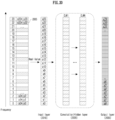
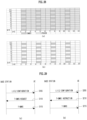
- FIG. 20 illustrates a 1D CNN structure for AI/ML-based channel estimation in a wireless communication system to which the present disclosure may be applied.
- channel estimation in the frequency domain and channel estimation in the time domain are performed separately.
- channel estimation in the time domain may be performed after channel estimation in the frequency domain (e.g., 1D Wiener filter).
- FIG. 20 illustrates how each layer of a CNN is constructed from channel estimate values (e.g., x0+jy0, ...) in the frequency domain.
- channel estimate values e.g., x0+jy0, ...) in the frequency domain.
- real values are exemplified, but it is obvious that the same can be applied to imaginary values.
- channel estimate value in the frequency domain is exemplified, it is obvious that the same can be applied to the channel estimate value in the time domain.
- the input layer 2010 of the CNN may be configured based on the channel estimate value (e.g., a real number among the channel estimate values).
- the shaded area 2005 may mean an area where DMRS is transmitted.
- N convolution layers/hidden layers 2020 e.g., N is a natural number greater than or equal to 1
- the output layer 2030 can be constructed from the result of the convolution layer/hidden layer 2020.
- Figure 21 illustrates an output value estimation method in a 1D CNN structure for AI/ML-based channel estimation in a wireless communication system to which the present disclosure can be applied.
- a feature map 2120 may be derived from an input value 2110 in each convolutional layer/hidden layer constituting a 1D CNN, and an output value 2130 may be estimated.
- the operation to derive the feature map 2120 in each convolutional layer/hidden layer may correspond to [S2110-a, S2110-b, S2110-c, ...], and the operation of estimating the output value 2130 based on the characteristic map 2120 may correspond to [S2120].
- a kernel/filter 2140 that applies a specific weight to the input value of a specific unit may be defined in order to derive the feature map 2120.
- Each kernel/filter 2140 may be defined with a specific size (or number of weights). Additionally, each kernel/filter 2140 may be defined as a combination of specific weights (e.g., w0/w1/w2/w3).
- Each kernel/filter 2140 may have a specific movement range for deriving the characteristic map 2120 within the input value 2110, and the specific movement range may be named a stride. Additionally, the kernel/filter 2140 may be defined differently for each convolution layer/hidden layer, or may be defined the same for all convolution layers/hidden layers.
- Figure 21 shows an example of a convolutional layer/hidden layer consisting of one kernel/filter 2140 set/defined to size 4 and stride 1.
- an activation function (AF) 2150 used to estimate the output value based on the feature map 2120 may be defined.
- An activation function 2150 may be used to add non-linearity to the feature map 2120 obtained through a convolution operation.
- the activation function 2150 may include a step function, sigmoid function, hyperbolic tangent function, ReLU function, Leaky ReLU function, softmax function, etc.
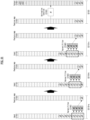
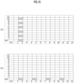
- FIG. 22 illustrates a 2D CNN structure for AI/ML-based channel estimation in a wireless communication system to which the present disclosure may be applied.
- channel estimation in the frequency domain and channel estimation in the time domain are performed together.
- channel estimation in the frequency domain and channel estimation in the time domain may be performed simultaneously (e.g., 2D Wiener filter).
- FIG. 22 illustrates how each layer of a CNN is constructed from channel estimate values (e.g., x0+jy0, ...) in the frequency domain.
- channel estimate values e.g., x0+jy0, ...) in the frequency domain.
- real values are exemplified, but it is obvious that the same may be applied to imaginary values.
- the method of configuring each layer of the 2D CNN structure in FIG. 22 is an extension of the method of configuring each layer of the 1D CNN structure in FIG. 20 to the two-dimensional time/frequency domain, and other configuration methods can be assumed to be the same.
- the input layer 2210 of the CNN may be configured based on the channel estimate value (e.g., a real number among the channel estimate values).
- the shaded area 2205 may mean an area where DMRS is transmitted.
- N convolution layers/hidden layers 2220 e.g., N is a natural number greater than or equal to 1 may be configured.
- the output layer 2230 may be constructed from the result of the convolution layer/hidden layer 2220.
- a feature map 2320 may be derived from the input value 2310 in each convolutional layer/hidden layer constituting the 2D CNN, and the output value 2330 may be estimated.
- the method for estimating the output value in FIG. 23 is an extension of the method for estimating the output value in FIG. 20 to the two-dimensional time/frequency domain, and other methods may be assumed to be the same.
- the operation to derive the feature map 2320 in each convolutional layer/hidden layer may correspond to [S2310-a, S2310-b, S2310-c, ...], and the operation of estimating the output value 2330 based on the characteristic map 2320 may correspond to [S2320].
- a kernel/filter 2340 that applies a specific weight to the input value of a specific unit may be defined in order to derive the feature map 2320.
- Each kernel/filter 2340 may be defined with a specific size (or number of weights). In this case, the specific size may be defined based on two dimensions (e.g., two-dimensional time/frequency domain). Additionally, each kernel/filter 2340 may be defined as a combination of specific weights (e.g., w00/w10/w20/w30/w01/w1121/w31).
- Each kernel/filter 2340 may have a specific movement range for deriving the characteristic map 2320 within the input value 2310, and the specific movement range may be named a stride.
- the stride may be defined based on two dimensions (e.g., two-dimensional time/frequency domain).
- the kernel/filter 2340 may be defined differently for each convolution layer/hidden layer, or may be defined the same for all convolution layers/hidden layers.
- Figure 23 shows an example of a convolutional layer/hidden layer consisting of one kernel/filter 2340 set/defined with size 4x2 and stride [1, 1] (e.g. [time domain, frequency domain]).
- an activation function (AF) 2350 used to estimate the output value based on the feature map 2320 may be defined.
- An activation function 2350 may be used to add non-linearity to the feature map 2320 obtained through a convolution operation.
- the activation function 2150 may include a step function, sigmoid function, hyperbolic tangent function, ReLU function, Leaky ReLU function, softmax function, etc.
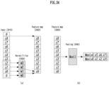
- FIG. 24 illustrates padding and pooling in a CNN structure for AI/ML-based channel estimation in a wireless communication system to which the present disclosure may be applied. Specifically, FIG. 24(a) illustrates a padding method, and FIG. 24(b) illustrates a pooling method.
- the feature map 2420 obtained as a result of the convolution operation is smaller in size than the input 2410, and a padding method can be used to prevent this.
- the padding method may refer to a function/operation/structure that ensures that the size of the feature map 2420 remains the same as the size of the input 2410 even after the convolution operation.
- FIG. 24(a) shows an example of applying zero padding in a 1D CNN structure.
- the pooling (or pooling layer) 2440 may refer to a function/operation/structure that reduces the size of the feature map 2420 by downsampling the feature map 2420.
- Examples of pooling operations include max pooling, average pooling, etc.
- Figure 24(b) shows an example of applying max pooling in a 1D CNN structure. The same concepts of kernel and stride can be applied to pooling operations, and in this example, a kernel of size 4 and a stride set to 4 are assumed.
- bias values may be applied in relation to the corresponding CNN structure.
- the bias value may be applied as an addition to a specific feature map to which the kernel is applied.
- the loss function may refer to a function that quantifies the difference between the actual value and the predicted value.
- MSE mean square error
- the optimizer may refer to a function for updating weight(s) appropriate for each layer based on the loss function.
- a batch gradient descent, stochastic gradient descent (SGD), and mini-batch gradient descent, momentum, adagrad, RMSprop, adam, etc. may be considered.
- the inference performance of that node can be improved.
- training results/information e.g. weights, bias, etc.
- the above-described update process e.g., weight/bias update using loss function/optimizer
- the proposed method in the present disclosure is proposed/described focusing on the CNN structure, but is not limited to the CNN structure. Therefore, it is clear that information exchange assuming other NN structures other than the CNN structure is possible based on the operating method/principle/structure of the proposed method.
- the above-described 1D CNN structure and 2D CNN structure are examples of structures mainly considered in the proposed method in this disclosure, and are not intended to limit the proposed method, so specific functions/operations are not limited by specific terms.
- the above-described function/operation/method is not limited to a specific term and may be replaced by another term.
- the drawing e.g., size expressed in FIGS. 20 to 24
- the proposed method in the present may be applied to other sizes.
- information about the AI/ML algorithm, NN structure, and parameter(s) related thereto may be shared between the base station and the terminal.
- the training process at the base station and/or terminal may be omitted, which has the effect of reducing the complexity and energy consumption required for the learning process.
- FIG. 25 is a diagram illustrating a signaling procedure between a base station and a user equipment (UE) for a method of reporting channel state information according to an embodiment of the present disclosure.
- UE user equipment
- FIG. 25 is for convenience of description and does not limit the scope of the present disclosure. Some step(s) illustrated in FIG. 25 may be omitted depending on the situation and/or configuration. Additionally, the order of some step(s) illustrated in FIG. 25 may be changed.
- the base station and UE in FIG. 25 are only examples, and may be implemented as devices illustrated in FIG. 32 below.
- the processors 102/202 of FIG. 32 can control transmission and reception of channels/signals/data/information, etc. using the transceivers 106/206, and may control to store transmitted or received channels/signals/data/information, etc. in the memory 104/204.
- the base station in FIG. 25 may refer to a network-level device.
- the method proposed in the present disclosure described above (Example: AI/ML-related information sharing method described above and Embodiment 1, Embodiment 2, and/or detailed Embodiments of each of Embodiments 1 and 2, etc.) may be referenced/used even if there is no separate mention.
- FIG. 25 shows the DNN structure as an example
- the signaling described in FIG. 25 may be extended and applied to the sharing and application of information related to AI/ML algorithms and/or DNN/NN structures.
- the UE may transmit/report the capability information of the corresponding UE to the base station.
- the UE may report capability information related to embodiments of the present disclosure (e.g., the above-described AI/ML-related information sharing method and Embodiments 1 to 2, etc.).
- the base station may perform (pre-)training for the DNN.
- the base station may obtain information about the parameter(s) required for the AI/ML algorithm and/or DNN/NN structure based on the learning process. For example, based on the process, the base station may obtain parameter(s) related to embodiments in the present disclosure (Example: AI/ML-related information sharing method described above and Embodiment 1, Embodiment 2, and/or detailed Embodiments of each of Embodiments 1 and 2, etc.).
- the base station may configure/indicate the UE about information related to the AI/ML algorithm and/or DNN/NN structure.
- the base station may configure/indicate the UE on information about the parameter(s) obtained in step S010.
- parameter(s) related to the embodiments in the present disclosure (Example: AI/ML-related information sharing method described above and Embodiment 1, Embodiment 2, and/or detailed Embodiments of each of Embodiments 1 and 2, etc.) may be configured/indicated to the UE.
- the base station may apply a DNN structure based on the AI/ML algorithm and/or DNN/NN structure shared with the UE. For example, the base station may apply DNN to compress the DL channel and/or RS (Reference Signal) and transmit them to the UE.
- RS Reference Signal
- the base station may transmit a DL channel and/or RS to the UE.
- a DL channel and/or RS may be transmitted to the UE.
- an AI/ML algorithm and/or DNN/NN structure shared with the UE may be applied.
- the UE may adjust DNN parameters based on the DL channel and/or RS.
- the UE can perform training based on the DL channel and/or RS, and adjust DNN parameters based on the training results.
- the UE may perform CSI reporting or transmit a UL channel and/or RS.
- the UE may perform CSI reporting on the results learned in step S035.
- the UE may apply DNN to compress CSI.
- the UE may apply DNN to compress the UL channel and/or RS and transmit them to the base station.
- the base station may apply DNN for CSI reporting, UL channel, and/or RS. For example, based on the AI/ML algorithm and/or DNN/NN structure already shared with the UE, the base station may decompress the CSI report, UL channel, and/or RS, or estimate/predict the CSI report, UL channel, and/or RS.
- the base station may tune DNN parameters based on CSI reporting, UL channel, and/or RS. For example, the base station may perform training based on the UL channel and/or RS, and adjust DNN parameters based on the training results. And/or, the base station may adjust the DNN parameters based on the UE's reported values.
- the base station may configure/indicate the UE to perform an update on the parameter(s) for the AI/ML algorithm and/or DNN/NN structure. For example, the UE may adjust/update DNN parameters based on the update configurations/indications of the corresponding base station.
- the UE may adjust DNN parameters. For example, as in the update configuration/indication in step S055, the UE may adjust the DNN parameters based on the value(s) configured/indicated by the base station based on L1/L2 signaling.
- FIG. 26 is a diagram illustrating an operation of a UE performing uplink transmission or downlink reception, according to an embodiment of the present disclosure.
- the artificial intelligence (AI) model may be included in a UE, but is not limited thereto and may be included in a base station or other device (e.g., a server/network node including a separate AI model, etc.).
- a base station or other device e.g., a server/network node including a separate AI model, etc.
- the AI model is included in a base station or other device above, when a UE inputs specific data into an AI model, it may mean that the UE transmits specific data (e.g., information related to RS, etc.) to a base station containing the AI model or the other device. Accordingly, specific data can be input to the AI model, and the AI model may output a channel estimation result based on the specific data.
- specific data e.g., information related to RS, etc.
- the learning and/or inference process of the AI model may be carried out in the UE, but is not limited thereto and may also be carried out in the base station and/or the other devices.
- the UE may receive first configuration information related to a specific reference signal (RS) for learning the AI model from the base station (S2610) .
- the specific RS may include at least one of DMRS, CSI-RS, SRS, or TRS.
- the UE may receive a DCI including information indicating transmission or reception of a specific RS from the base station (S2620).
- the DCI or first configuration information may include domain indication information indicating the domain through which a specific RS is transmitted. That is, the domain indication information may indicate the domain in which a specific RS pattern is transmitted, either the time domain or the frequency domain.
- the UE may perform reception or transmission of a specific RS in a specific symbol.
- the UE may perform repeated reception or repeated transmission of a specific RS from a specific RE (in specific time units).
- the DCI or first configuration information may include pattern information of a specific RS.
- the pattern information may include at least one of a type of specific RS, position of additional specific RS, maximum length of specific RS (or maximum number of OFDM symbols), number of CDM groups associated with specific RS, time or frequency density of a specific RS, or port index of a specific RS.
- the DCI or first configuration information may include time and frequency resource information for transmission or reception of a specific RS.
- the frequency resource information may include at least one of a BWP or a cell where transmission or reception of a specific RS will be performed.
- the time information may include at least one of the transmission period of a specific RS, an offset related to the period, a section, or the number of symbols.
- the UE may receive a specific RS from the base station or transmit a specific RS to the base station without receiving the data channel corresponding to the specific RS (S2630).
- the data channel may include at least one of PUCCH, PUSCH, PDCCH, PDSCH, PBCH, or PRACH.
- the UE may transmit a DMRS for the PUSCH to the base station or receive a DMRS for the PDSCH from the base station without transmitting the PUSCH or receiving the PDSCH.
- the pattern of the NZP CSI-RS resource may be determined based on the pattern information of the DMRS configured for the BWP (e.g., 'DMRS-DownlinkConfig') corresponding to the second configuration information (e.g., 'CSI-ResourceConfig') related to the NZP CSI-RS resource.
- the pattern information of the DMRS configured for the BWP e.g., 'DMRS-DownlinkConfig'
- the second configuration information e.g., 'CSI-ResourceConfig'
- the pattern of the NZP CSI-RS resource may be determined based on the pattern information of the DMRS configured for the BWP and the PDSCH mapping type information corresponding to the NZP CSI-RS resource.
- a specific BWP ID is included in the second configuration information related to the NZP CSI-RS resource, and the pattern of the NZP CSI-RS resource may be determined based on pattern information of the DMRS corresponding to the specific BWP ID.
- the pattern of the SRS resource may be determined based on the DMRS pattern information (e.g., 'DMRS-UplinkConfig') configured for the BWP corresponding to the third configuration information (e.g., 'SRS-Config') related to the SRS resource.
- the DMRS pattern information e.g., 'DMRS-UplinkConfig'
- the third configuration information e.g., 'SRS-Config'
- the pattern of the SRS resource may be determined based on the pattern information of the DMRS configured for the BWP and the PUSCH mapping type information corresponding to the SRS resource.
- Figure 27 is a diagram illustrating the operation of a base station for the channel state information reporting method according to an embodiment of the present disclosure.
- the base station may transmit first configuration information related to a specific RS for learning the AI model to the UE (S2710).
- the base station may transmit DCI containing information indicating transmission or reception of a specific RS to the UE (S2720).
- the base station may transmit the specific RS to the UE or receive the specific RS from the UE without receiving the data channel corresponding to the specific RS (S2730).
- Embodiment 1 relates to a method for a base station/UE to transmit DMRS of the data transmission channel without data transmission for online learning.
- FIG. 28 (a) shows an example of a method in which a base station/terminal transmits data and DMRS of the data transmission channel.
- the PDSCH mapping type e.g., PDSCH mapping type A
- (DMRS) configuration type e.g., configuration type 1
- the UE may estimate the wireless channel of the slot and bandwidth corresponding to the PDSCH scheduled for the UE using DMRS transmitted in the 2nd, 5th, 8th, and 11th OFDM symbols.
- the UE may utilize the estimated radio channel information in the decoding process of the scheduled PDSCH (that is, transmitted from the 2nd to the 13th OFDM symbol).
- FIG. 28 (b) shows an example of a method in which a base station/UE transmits the DMRS of the data transmission channel without data transmission (i.e., without PDSCH transmission) for online learning.
- the terminal can use DMRS to update (or fine tune) the weights and biases required for the AI/ML algorithm.
- (DMRS) configuration type e.g., configuration type 1
- location for additional DMRS e.g., PDSCH mapping type A
- FIGS. 28 (a) and (b) show examples of PDSCH and PDSCH DMRS, but the present disclosure may be extended and applied to data channels such as PBCH/PUSCH/PUCCH/PDCCH.
- online learning may be necessary to update the algorithm's weights and biases.
- the accuracy and efficiency of learning can be increased. Additionally, since unnecessary data transmission may be avoided, interference with data channels of other UEs can be reduced and resource efficiency can be increased.
- DMRS transmission without data transmission is referred to as 'T(training)-DMRS'.
- T-DMRS may have UE-specific/UE-group specific (e.g., multicast)/cell-specific (e.g., broadcast) characteristics.
- the parameters may be configured/indicated for the UE in a UE-specific/UE-group-specific (e.g., multicast)/cell-specific (e.g., broadcast) manner.
- Embodiment 1-1 relates to a method for a base station to indicate a UE to transmit T-DMRS (i.e., indications for UL RS transmission) and/or a method for a terminal to request T-DMRS transmission to a base station (i.e., a request for DL RS transmission).
- the base station may indicate the UE to transmit T-DMRS to update the weights and biases of the AI/ML algorithm for channel estimation. Additionally or alternatively, the UE may request T-DMRS transmission from the base station to update the weights and biases of the AI/ML algorithm for channel estimation.
- FIG. 29 (a) shows an example in which a UE requests T-DMRS transmission from a base station.
- the base station may transmit configuration information (or configuration values) related to T-DMRS transmission to the UE (before the terminal requests T-DMRS) (S105).
- the UE may request DL T-DMRS transmission from the base station based on the configuration information (or configuration value) and/or other request information (S110).
- the base station may transmit a DL T-DMRS to the terminal based on the terminal's request and/or the configuration information (or configuration value) (115).
- FIG. 29 (b) shows an example in which the base station indicates the UE to transmit T-DMRS.
- the base station may transmit configuration information (or configuration values) related to T-DMRS transmission to the UE (before indicating the UE to transmit T-DMRS) (S205).
- the base station may indicate the UE to transmit UL T-DMRS based on the configuration information and/or other indication information (S210).
- the UE may transmit the UL T-DMRS to the base station based on the base station's indications and/or the configuration information (or configuration value) (S215).
- the base station/UE instructs/requests T-DMRS transmission only when additional RS transmission is necessary, so that resources for RS transmission can be utilized more efficiently.
- Embodiment 1-2 relates to a method of including (required) RS pattern information when indicating/requesting T-DMRS transmission.
- an indication/request for T-DMRS transmission may include information indicating/requesting RS pattern information.
- information indicating/requesting RS pattern information may be transmitted and received separately from the indication/request for T-DMRS transmission.
- DMRS type e.g., 'dmrs-Type'
- maximum length 'maxLength'
- scrambling ID e.g., 'scramblingID0, or/and 'scramblingID1'
- number of CDM groups RS time/frequency density, port index, and number of OFDM symbols.
- the port index may be configured/indicated/defined to assume a single port.
- the port index may be configured/indicated/defined as 1000, etc.
- a method of including 'RS pattern information' may be applied to a predefined DMRS pattern. Based on information (or value) configured in the UE for DL/UL DMRS transmission and reception, a value that can indicate a specific pattern (among DMRS patterns that can be received/transmitted) may be transmitted and received.
- FIG. 30 shows an example of a predefined DL DMRS pattern.
- the final DMRS pattern may be determined based on the table in FIG. 30 and information configured for the UE (e.g., PDSCH mapping type, location for additional DMRS, and Id).
- a specific DMRS pattern may be determined based on the Id value among all four DMRS patterns from p0 to p3.
- a method of indicating/determining a DMRS pattern with a bitmap by defining bits corresponding to each pattern is supported, and/or a combinatorial method (e.g., log2(X) bits) that can select one pattern among all possible patterns may be supported.
- An example of the number of bits required for each case in FIG. 30 may be shown in Table 6 below.
- Table 6 PDSCH mapping type A PDSCH mapping type B pos0 pos1 pos2 pos3 pos0 pos1 pos2 pos3 bitmap 1 bit 4 bits 4 bits 4 bits 1 bit 6 bits 6 bits 5 bits Combin atoria l method 1 bit 2 bits 2 bits 2 bits 1 bit 3 bits 3 bits 3 bits 3 bits 3 bits
- candidate patterns may be limited to some of all patterns to reduce the number of bits. Additionally or alternatively, in the above example, a method of determining a candidate pattern is described based on the PDSCH mapping type preset for the terminal and the location of the additional DMRS, but regardless of this, the candidate pattern may be defined for all possible patterns. For example, when PDSCH mapping type A is configured for the UE, 7 DMRS patterns that are unrelated to the configuration value related to the location of the additional DMRS can be defined as candidate patterns.
- the DMRS pattern may be determined based on preset values for DMRS reception/transmission, such as 'dmrs-Type' and 'maxLength'.
- RS pattern information may be included (in information indicating/requesting T-DMRS) both when the base station indicates the UE to transmit UL T-DMRS and/or when the UE requests the base station to transmit DL T-DMRS.
- RS pattern information may be configured/indicated (prior to the T-DMRS indication/request and/or prior to T-DMRS transmission), or RS pattern information may be predefined as a fixed value.
- the configuration/indication information may have UE-specific/UE-group specific (e.g., multicast)/cell-specific (e.g., broadcast) characteristics.
- the corresponding parameters may be configured/indicated to the UE in a UE-specific/UE-group-specific (e.g., multicast)/cell-specific (e.g., broadcast) manner.
- Embodiment 1-3 relates to a method of indicating/requesting that only the RS pattern in a specific region among frequency or time domain RS patterns be transmitted when the UE/base station indicates/requests T-DMRS transmission.
- the RS patterns may be transmitted as shown in (b) of FIG. 28 .
- DMRS of a single OFDM symbol may be transmitted. That is, one symbol of DMRS may be transmitted in a specific OFDM symbol.
- the DMRS of a single RE may be transmitted. That is, a DMRS of 1 RE may be transmitted in a specific RE.
- an RS pattern composed of 1 RE may be transmitted repeatedly in specific units (e.g., x (P)RB/RE/PRG) (x is a natural number greater than or equal to 1) and/or may be transmitted within a specific duration (e.g., scheduling/configured bandwidth, etc.).
- specific units e.g., x (P)RB/RE/PRG) (x is a natural number greater than or equal to 1) and/or may be transmitted within a specific duration (e.g., scheduling/configured bandwidth, etc.).
- the 'method of transmitting only RS patterns in a specific area' may be applied both when the base station indicates the UE to transmit UL T-DMRS and/or when the UE requests DL T-DMRS transmission from the base station.
- a 'method of transmitting only the RS pattern of a specific area' may be configured/indicated (before the T-DMRS indication/request and/or before T-DMRS transmission).
- 'a method of transmitting only the RS pattern of a specific area' may be defined in advance.
- the configuration/indication information may have UE-specific/UE-group specific (e.g., multicast)/cell-specific (e.g., broadcast) characteristics.
- the corresponding parameters may be configured/indicated to the UE in a UE-specific/UE-group-specific (e.g., multicast)/cell-specific (e.g., broadcast) manner.
- the weights and biases for channel estimation in the frequency domain and time domain can be defined separately. Resources may be utilized more efficiently by separately transmitting the RS pattern in the frequency domain and the RS pattern in the time domain depending on the channel situation.
- channel estimation in the frequency domain may be related to correlation in the frequency domain and average delay/delay spread characteristics of the channel.
- channel estimation in the time domain may be related to correlation in the time domain and Doppler shift/Doppler spread characteristics of the channel.
- a situation may occur in which only the channel characteristics in the time domain change while the channel characteristics in the frequency domain remain almost unchanged, and the opposite situation may also occur.
- the channel state may change depending on different characteristics, and by transmitting RS patterns in the frequency or time domain independently from each other depending on the situation of the base station/UE, unnecessary RS transmission may be minimized and resource efficiency can be improved.
- Embodiment 1-4 relates to a method of including time/frequency resource area information in which an RS (e.g., DMRS) to indicate/request T-DMRS transmission will be transmitted.
- an indication/request for T-DMRS transmission may include time/frequency resource area information where RS will be transmitted.
- time/frequency resource area information where RS will be transmitted may be transmitted and received separately from the indication/request for T-DMRS transmission.
- Time/frequency resource area information where RS will be transmitted may include at least one of cell (index), BWP (index), bandwidth, subcarrier (index), number of OFDM symbols, period (e.g., Periodic, Semi-persistent, Aperiodic), offset in periodicity, or duration.
- time/frequency resource area information in which RS will be transmitted may be configured/indicated.
- time/frequency resource area information where RS will be transmitted may be defined in advance.
- the configuration/indication information may have UE-specific/UE-group specific (e.g., multicast)/cell-specific (e.g., broadcast) characteristics.
- the corresponding parameters may be configured/indicated to the UE in a UE-specific/ UE-group-specific (e.g., multicast)/cell-specific (e.g., broadcast) manner.
- Embodiment 1-5 relates to a method for a base station to define a new DCI format and/or a new RNTI to indicate the UE to transmit T-DMRS.
- a terminal configured/indicated to transmit uplink T-DMRS based on a new DCI format/new RNTI may transmit the uplink T-DMRS.
- a UE that has been configured/instructed to transmit downlink T-DMRS may receive downlink T-DMRS.
- a UE that configures/indicates downlink T-DMRS transmission based on the DCI format and/or RNTI and receives downlink T-DMRS accordingly may not separately transmit HARQ ACK for DCI (e.g., scheduling DCI) corresponding to the above T-DMRS configuration/indication to the base station.
- DCI e.g., scheduling DCI
- the method of the present disclosure may be extended and applied to DL/UL RS (e.g., CSI-RS/SRS/TRS, etc.) other than DMRS.
- the method of the present disclosure may be extended and applied as a method for transmitting (additional) RS for learning (AI/ML algorithm and/or NN).
- the RS for learning AI/ML algorithms like T-DMRS, may be named T-RS.
- PDSCH/PUSCH has been described as an Embodiment of a channel for transmitting data, but it is not limited thereto.
- the method of the present disclosure may be extended and applied to channels that transmit data other than PDSCH/PUSCH (e.g., PDCCH/PUCCH/PBCH/PRACH, etc.).
- the method of the present disclosure may be extended and applied to a method for transmitting (additional) RS for learning (of AI/ML algorithm and/or NN).
- the above-described PDSCH/PUSCH/PDCCH/PUCCH, etc. may be named data/control-less PxxCH (e.g., data-less PDSCH/PUSCH, UCI-less PUCCH, DCI-less PDCCH, etc.).
- UCI-less PUCCH For periodic RS transmission of data/control-less PxxCH, UCI-less PUCCH, DCI-less PDCCH, etc. may be considered.
- DMRS patterns may be defined differently for each format.
- PUCCH format for sequence detection e.g., format 0/1
- DMRS may not be transmitted/received separately.
- a separate transmission method e.g., a method of transmitting PUCCH corresponding to the promised UCI bit
- a method for specifying the transmission method of the PUCCH i.e., a method of transmitting a predefined UCI PUCCH
- a predefined UCI PUCCH may be separately defined.
- a method in which the data/control payload (e.g., predefined DL/UL-SCH, predefined data sequence, predefined DCI/UCI, etc.) promised (or configured/indicated in advance) between the base station/UE is transmitted and received together with the DMRS for learning may be applied.
- the data/control payload e.g., predefined DL/UL-SCH, predefined data sequence, predefined DCI/UCI, etc.
- SPS PDSCH transmission without DL-SCH (DL-SCH less) and/or SPS PUSCH with UL-SCH less may be defined/configured/indicated.
- SPS PDSCH/PUSCH transmission may be configured/indicated by RRC signaling, or RRC signaling and DCI. If SPS PDSCH/PUSCH is configured/indicated by RRC signaling and DCI, activation/deactivation (or release) may be controlled by DCI, and thus resources may be utilized more efficiently.
- Embodiment 2 a method for transmitting and receiving a DMRS pattern based on the CSI-RS/SRS configuration/indication method will be described.
- Table 7, Table 8, Table 9, and Table 10 respectively show the relationship between parameters for configuring DMRS/CSI-RS/SRS.
- DL DMRS may be configured by 'DMRS-DownlinkConfig' for each BWP in a specific serving cell.
- NZP CSI-RS resources can be set by 'NZP-CSI-RS-Resource' within a specific serving cell, and can be set to correspond to a specific BWP by 'CSI-ResourceConfig'.
- UL DMRS may be configured by 'DMRS-UplinkConfig' for each BWP within a specific serving cell.
- SRS resources may be configured by 'SRS-Resource' for each BWP within a specific serving cell.
- Embodiment 2-1 relates to a method of connecting/corresponding to a specific DMRS configuration value in CSI-RS and/or SRS configuration/indication and a method for determining the pattern of CSI-RS and/or SRS based on the specific connected/corresponding DMRS configuration value.
- 'CSI-RS and/or SRS configuration/indication' may mean configuration/indication for CSI-RS resource (set)/SRS resource (set) .
- BWP information e.g., BWP ID
- BWP ID a specific (DL) DMRS configuration value
- Option 1-1 a specific (DL) DMRS configuration value
- a specific BWP ID may be configured/indicated directly for a specific NZP CSI-RS resource/NZP CSI-RS resource set, and a pattern of a specific NZP CSI-RS resource/NZP CSI-RS resource set may be determined based on the DMRS configuration value configured for the specific BWP.
- 'BWP including a specific (DL) DMRS configuration value' may mean a BWP corresponding to the same serving cell as the serving cell in which the CSI-RS is configured/indicated. Additionally or alternatively, serving cell information corresponding to 'BWP containing specific (DL) DMRS configuration value' may be additionally set/indicated.
- PDSCH mapping type information e.g., Type A or Type B
- a specific (DL) DMRS configuration value may be connected/corresponding to the CSI-RS configuration/indication (Option 1-2).
- a pattern of a specific NZP CSI-RS resource/NZP CSI-RS resource set (e.g., 'dmrs-DownlinkForPDSCH-MappingTypeA' or 'dmrs-DownlinkForPDSCH-MappingTypeB') may be determined.
- BWP information e.g., BWP ID
- UL DMRS configuration value
- a specific BWP may be configured/indicated to correspond to 'SRS-Config' in which one or more SRS resources and/or one or more SRS resource sets may be included/configured.
- the pattern of a specific SRS resource/SRS resource set may be determined based on the DMRS configuration value (e.g., 'DMRS-UplinkConfig') configured in the BWP corresponding to the 'SRS-Config' in which the specific SRS resource/SRS resource set is included/configured.
- the DMRS configuration value e.g., 'DMRS-UplinkConfig'
- a specific BWP ID may be directly set/indicated for a specific SRS resource/SRS resource set, and the pattern of the specific SRS resource/SRS resource set may be determined based on the DMRS configuration value set for the specific BWP.
- 'BWP including a specific (UL) DMRS configuration value' may mean a BWP corresponding to the same serving cell as the serving cell in which the SRS is set/indicated. Additionally or alternatively, serving cell information corresponding to 'BWP including specific (UL) DMRS configuration value' may be additionally configured/indicated.
- PDSCH mapping type information e.g., TypeA or TypeB
- UL DMRS configuration/indication
- a pattern (e.g., 'dmrs-UplinkForPUSCH-MappingTypeA' or 'dmrs-UplinkForPUSCH-MappingTypeB') of a specific SRS resource/SRS resource set may be determined.
- information on the scheduling method e.g., based on DCI/RRC/MAC CE
- a specific (UL) DMRS configuration value may be connected/corresponding to the SRS configuration/indication (Option 2-3).
- the DMRS configuration value for 'pusch-Config' (e.g., 'dmrs-UplinkForPUSCH-MappingTypeA' or 'dmrs-UplinkForPUSCH-MappingTypeB') and the DMRS configuration value for 'configuredGrantConfig' (e.g., cg-DMRS-Configuration) may be configured, respectively.
- a pattern of a specific SRS resource/SRS resource set (e.g., 'dmrs-UplinkForPUSCH-MappingTypeA', 'dmrs-UplinkForPUSCH-MappingTypeB', or 'cg-DMRS-Configuration') may be determined.
- the pattern of CSI-RS/SRS and DMRS may be different. However, based on Example 2-1, the same CSI-RS/SRS pattern as the DMRS pattern may be configured/indicated/defined.
- DL/UL DMRS-related configuration values are already included in parameters containing CSI-RS configuration values (e.g., 'ServingCellConfig') or parameters containing SRS configuration values (e.g., 'BWP-UplinkDedicated' or 'ServingCellConfig'), the corresponding configuration values may be used as is.
- parameters containing CSI-RS configuration values e.g., 'ServingCellConfig'
- SRS configuration values e.g., 'BWP-UplinkDedicated' or 'ServingCellConfig'
- the UE/base station may perform online learning based on CSI-RS/SRS of the same pattern as the actual DMRS before receiving the actual DMRS corresponding to the PDSCH/PUSCH transmission.
- the same pattern as the DL/UL DMRS may be configured/indicated based on one or more parameters in the CSI-RS and/or SRS configuration/indication information for defining the CSI-RS/SRS pattern.
- the RS sequence for CSI-RS/SRS may be directly applied to the RS sequence configured/indicated in the DMRS corresponding to the CSI-RS/SRS. Additionally or alternatively, a separate RS sequence for the RS sequence for CSI-RS/SRS may be configured/indicated.
- the remaining parameters excluding the pattern may be determined based on predefined values (e.g., 'frqBand', 'powerControlOffset', 'powerControlOffsetSS', 'periodicityAndOffset', or 'qcl-InforPeriodicCSI-RS', etc.).
- predefined values e.g., 'frqBand', 'powerControlOffset', 'powerControlOffsetSS', 'periodicityAndOffset', or 'qcl-InforPeriodicCSI-RS', etc.
- Embodiment 2-2 relates to a method in which a UE requests a CSI-RS for demodulation from a base station before the operation according to embodiment 2-1.
- the UE may request CSI-RS transmission for demodulation from the base station.
- resource information for which CSI-RS is desired to be transmitted may include a bitmap indicating the resource information or information indicating the number of RBs and starting RB.
- Embodiment 2-3 relates to a method for the base station to configure/indicate the UE on precoding information to be applied to the SRS port when SRS triggering is performed.
- precoding information to be applied to each port may be configured/indicated while triggering x-port SRS (or x SRS resource with 1-port SRS).
- Embodiment 2-4 relates to a method by which a base station configures/indicates the UE to transmit SRS transmission resource region information when SRS triggering is performed.
- the base station may trigger SRS using a newly defined field in DCI and set/instruct the UE with resource allocation (RA) information for SRS transmission (e.g., RA information in bitmap form or information indicating the number of RBs and the starting RB, etc.).
- RA resource allocation
- the UE may transmit SRS based on RA information of the PDSCH/PUSCH scheduled with the DCI.
- FIG. 32 is a diagram which illustrates a block diagram of a wireless communication system according to an embodiment of the present disclosure.
- a first device 100 and a second device 200 may transmit and receive a wireless signal through a variety of radio access technologies (e.g., LTE, NR).
- radio access technologies e.g., LTE, NR.
- a first device 100 may include one or more processors 102 and one or more memories 104 and may additionally include one or more transceivers 106 and/or one or more antennas 108.
- a processor 102 may control a memory 104 and/or a transceiver 106 and may be configured to implement description, functions, procedures, proposals, methods and/or operation flow charts included in the present disclosure.
- a processor 102 may transmit a wireless signal including first information/signal through a transceiver 106 after generating first information/signal by processing information in a memory 104.
- a processor 102 may receive a wireless signal including second information/signal through a transceiver 106 and then store information obtained by signal processing of second information/signal in a memory 104.
- a memory 104 may be connected to a processor 102 and may store a variety of information related to an operation of a processor 102.
- a memory 104 may store a software code including commands for performing all or part of processes controlled by a processor 102 or for performing description, functions, procedures, proposals, methods and/or operation flow charts included in the present disclosure.
- a processor 102 and a memory 104 may be part of a communication modem/circuit/chip designed to implement a wireless communication technology (e.g., LTE, NR).
- a transceiver 106 may be connected to a processor 102 and may transmit and/or receive a wireless signal through one or more antennas 108.
- a transceiver 106 may include a transmitter and/or a receiver.
- a transceiver 106 may be used together with a RF (Radio Frequency) unit.
- a wireless device may mean a communication modem/circuit/chip.
- a second device 200 may include one or more processors 202 and one or more memories 204 and may additionally include one or more transceivers 206 and/or one or more antennas 208.
- a processor 202 may control a memory 204 and/or a transceiver 206 and may be configured to implement description, functions, procedures, proposals, methods and/or operation flows charts included in the present disclosure.
- a processor 202 may generate third information/signal by processing information in a memory 204, and then transmit a wireless signal including third information/signal through a transceiver 206.
- a processor 202 may receive a wireless signal including fourth information/signal through a transceiver 206, and then store information obtained by signal processing of fourth information/signal in a memory 204.
- a memory 204 may be connected to a processor 202 and may store a variety of information related to an operation of a processor 202.
- a memory 204 may store a software code including commands for performing all or part of processes controlled by a processor 202 or for performing description, functions, procedures, proposals, methods and/or operation flow charts included in the present disclosure.
- a processor 202 and a memory 204 may be part of a communication modem/circuit/chip designed to implement a wireless communication technology (e.g., LTE, NR).
- a transceiver 206 may be connected to a processor 202 and may transmit and/or receive a wireless signal through one or more antennas 208.
- a transceiver 206 may include a transmitter and/or a receiver.
- a transceiver 206 may be used together with a RF unit.
- a wireless device may mean a communication modem/circuit/chip.
- one or more protocol layers may be implemented by one or more processors 102, 202.
- one or more processors 102, 202 may implement one or more layers (e.g., a functional layer such as PHY, MAC, RLC, PDCP, RRC, SDAP).
- One or more processors 102, 202 may generate one or more PDUs (Protocol Data Unit) and/or one or more SDUs (Service Data Unit) according to description, functions, procedures, proposals, methods and/or operation flow charts included in the present disclosure.
- PDUs Protocol Data Unit
- SDUs Service Data Unit
- One or more processors 102, 202 may generate a message, control information, data or information according to description, functions, procedures, proposals, methods and/or operation flow charts included in the present disclosure.
- One or more processors 102, 202 may generate a signal (e.g., a baseband signal) including a PDU, a SDU, a message, control information, data or information according to functions, procedures, proposals and/or methods disclosed in the present disclosure to provide it to one or more transceivers 106, 206.
- a signal e.g., a baseband signal
- One or more processors 102, 202 may receive a signal (e.g., a baseband signal) from one or more transceivers 106, 206 and obtain a PDU, a SDU, a message, control information, data or information according to description, functions, procedures, proposals, methods and/or operation flow charts included in the present disclosure.
- a signal e.g., a baseband signal
- One or more processors 102, 202 may be referred to as a controller, a micro controller, a micro processor or a micro computer.
- One or more processors 102, 202 may be implemented by a hardware, a firmware, a software, or their combination.
- one or more ASICs Application Specific Integrated Circuit
- one or more DSPs Digital Signal Processor
- one or more DSPDs Digital Signal Processing Device
- one or more PLDs PROgrammable Logic Device
- FPGAs Field Programmable Gate Arrays
- Description, functions, procedures, proposals, methods and/or operation flow charts included in the present disclosure may be implemented by using a firmware or a software and a firmware or a software may be implemented to include a module, a procedure, a function, etc.
- a firmware or a software configured to perform description, functions, procedures, proposals, methods and/or operation flow charts included in the present disclosure may be included in one or more processors 102, 202 or may be stored in one or more memories 104, 204 and driven by one or more processors 102, 202.
- Description, functions, procedures, proposals, methods and/or operation flow charts included in the present disclosure may be implemented by using a firmware or a software in a form of a code, a command and/or a set of commands.
- One or more memories 104, 204 may be connected to one or more processors 102, 202 and may store data, a signal, a message, information, a program, a code, an instruction and/or a command in various forms.
- One or more memories 104, 204 may be configured with ROM, RAM, EPROM, a flash memory, a hard drive, a register, a cash memory, a computer readable storage medium and/or their combination.
- One or more memories 104, 204 may be positioned inside and/or outside one or more processors 102, 202.
- one or more memories 104, 204 may be connected to one or more processors 102, 202 through a variety of technologies such as a wire or wireless connection.
- One or more transceivers 106, 206 may transmit user data, control information, a wireless signal/channel, etc. mentioned in methods and/or operation flow charts, etc. of the present disclosure to one or more other devices.
- One or more transceivers 106, 206 may receiver user data, control information, a wireless signal/channel, etc. mentioned in description, functions, procedures, proposals, methods and/or operation flow charts, etc. included in the present disclosure from one or more other devices.
- one or more transceivers 106, 206 may be connected to one or more processors 102, 202 and may transmit and receive a wireless signal.
- one or more processors 102, 202 may control one or more transceivers 106, 206 to transmit user data, control information or a wireless signal to one or more other devices.
- one or more processors 102, 202 may control one or more transceivers 106, 206 to receive user data, control information or a wireless signal from one or more other devices.
- one or more transceivers 106, 206 may be connected to one or more antennas 108, 208 and one or more transceivers 106, 206 may be configured to transmit and receive user data, control information, a wireless signal/channel, etc. mentioned in description, functions, procedures, proposals, methods and/or operation flow charts, etc.
- one or more antennas may be a plurality of physical antennas or a plurality of logical antennas (e.g., an antenna port).
- One or more transceivers 106, 206 may convert a received wireless signal/channel, etc. into a baseband signal from a RF band signal to process received user data, control information, wireless signal/channel, etc. by using one or more processors 102, 202.
- One or more transceivers 106, 206 may convert user data, control information, a wireless signal/channel, etc. which are processed by using one or more processors 102, 202 from a baseband signal to a RF band signal. Therefore, one or more transceivers 106, 206 may include an (analogue) oscillator and/or a filter.
- Embodiments described above are that elements and features of the present disclosure are combined in a predetermined form. Each element or feature should be considered to be optional unless otherwise explicitly mentioned. Each element or feature may be implemented in a form that it is not combined with other element or feature.
- an embodiment of the present disclosure may include combining a part of elements and/or features. An order of operations described in embodiments of the present disclosure may be changed. Some elements or features of one embodiment may be included in other embodiment or may be substituted with a corresponding element or a feature of other embodiment. It is clear that an embodiment may include combining claims without an explicit dependency relationship in claims or may be included as a new claim by amendment after application.
- a scope of the present disclosure includes software or machine-executable commands (e.g., an operating system, an application, a firmware, a program, etc.) which execute an operation according to a method of various embodiments in a device or a computer and a non-transitory computer-readable medium that such a software or a command, etc. are stored and are executable in a device or a computer.
- a command which may be used to program a processing system performing a feature described in the present disclosure may be stored in a storage medium or a computer-readable storage medium and a feature described in the present disclosure may be implemented by using a computer program product including such a storage medium.
- a storage medium may include a high-speed random-access memory such as DRAM, SRAM, DDR RAM or other random-access solid state memory device, but it is not limited thereto, and it may include a nonvolatile memory such as one or more magnetic disk storage devices, optical disk storage devices, flash memory devices or other nonvolatile solid state storage devices.
- a memory optionally includes one or more storage devices positioned remotely from processor(s).
- a memory or alternatively, nonvolatile memory device(s) in a memory include a non-transitory computer-readable storage medium.
- a feature described in the present disclosure may be stored in any one of machine-readable mediums to control a hardware of a processing system and may be integrated into a software and/or a firmware which allows a processing system to interact with other mechanism utilizing a result from an embodiment of the present disclosure.
- a software or a firmware may include an application code, a device driver, an operating system and an execution environment/container, but it is not limited thereto.
- a wireless communication technology implemented in a device 100, 200 of the present disclosure may include Narrowband Internet of Things for a low-power communication as well as LTE, NR and 6G.
- an NB-IoT technology may be an example of a LPWAN(Low Power Wide Area Network) technology, may be implemented in a standard of LTE Cat NB1 and/or LTE Cat NB2, etc. and is not limited to the above-described name.
- a wireless communication technology implemented in a wireless device 100, 200 of the present disclosure may perform a communication based on a LTE-M technology.
- a LTE-M technology may be an example of a LPWAN technology and may be referred to a variety of names such as an eMTC (enhanced Machine Type Communication), etc.
- an LTE-M technology may be implemented in at least any one of various standards including 1) LTE CAT 0, 2) LTE Cat M1, 3) LTE Cat M2, 4) LTE non-BL(non-Bandwidth Limited), 5) LTE-MTC, 6) LTE Machine Type Communication, and/or 7) LTE M and so on and it is not limited to the above-described name.
- a wireless communication technology implemented in a wireless device 100, 200 of the present disclosure may include at least any one of a ZigBee, a Bluetooth and a low power wide area network (LPWAN) considering a low-power communication and it is not limited to the above-described name.
- a ZigBee technology may generate PAN(personal area networks) related to a small/low-power digital communication based on a variety of standards such as IEEE 802.15.4, etc. and may be referred to as a variety of names.
- a method proposed by the present disclosure is mainly described based on an example applied to 3GPP LTE/LTE-A, 5G system, but may be applied to various wireless communication systems other than the 3GPP LTE/LTE-A, 5G system.
Landscapes
- Engineering & Computer Science (AREA)
- Signal Processing (AREA)
- Computer Networks & Wireless Communication (AREA)
- Theoretical Computer Science (AREA)
- Software Systems (AREA)
- Physics & Mathematics (AREA)
- Artificial Intelligence (AREA)
- General Engineering & Computer Science (AREA)
- Mathematical Physics (AREA)
- General Physics & Mathematics (AREA)
- Data Mining & Analysis (AREA)
- Evolutionary Computation (AREA)
- Computing Systems (AREA)
- Computational Linguistics (AREA)
- Computer Vision & Pattern Recognition (AREA)
- Medical Informatics (AREA)
- Molecular Biology (AREA)
- General Health & Medical Sciences (AREA)
- Biomedical Technology (AREA)
- Biophysics (AREA)
- Life Sciences & Earth Sciences (AREA)
- Health & Medical Sciences (AREA)
- Power Engineering (AREA)
- Mobile Radio Communication Systems (AREA)
Applications Claiming Priority (3)
| Application Number | Priority Date | Filing Date | Title |
|---|---|---|---|
| KR20210150319 | 2021-11-04 | ||
| KR20210156334 | 2021-11-15 | ||
| PCT/KR2022/017037 WO2023080636A1 (ko) | 2021-11-04 | 2022-11-02 | 무선 통신 시스템에서 상향링크 또는 하향링크 송수신을 수행하는 방법 및 장치 |
Publications (2)
| Publication Number | Publication Date |
|---|---|
| EP4429154A1 true EP4429154A1 (de) | 2024-09-11 |
| EP4429154A4 EP4429154A4 (de) | 2025-10-08 |
Family
ID=86241800
Family Applications (1)
| Application Number | Title | Priority Date | Filing Date |
|---|---|---|---|
| EP22890367.0A Pending EP4429154A4 (de) | 2021-11-04 | 2022-11-02 | Verfahren und vorrichtung zur durchführung von uplink- oder downlink-übertragung/-empfang in einem drahtloskommunikationssystem |
Country Status (4)
| Country | Link |
|---|---|
| US (1) | US20250008347A1 (de) |
| EP (1) | EP4429154A4 (de) |
| KR (1) | KR20240099312A (de) |
| WO (1) | WO2023080636A1 (de) |
Cited By (1)
| Publication number | Priority date | Publication date | Assignee | Title |
|---|---|---|---|---|
| WO2026065287A1 (zh) * | 2024-09-29 | 2026-04-02 | Oppo广东移动通信有限公司 | 传输参数确定方法及装置、通信设备、芯片、存储介质、程序、程序产品 |
Families Citing this family (1)
| Publication number | Priority date | Publication date | Assignee | Title |
|---|---|---|---|---|
| EP4716996A1 (de) * | 2023-05-23 | 2026-04-01 | QUALCOMM Incorporated | Referenzsignale in zusammenhang mit künstlicher intelligenz oder maschinenlernleistungsüberwachung |
Family Cites Families (38)
| Publication number | Priority date | Publication date | Assignee | Title |
|---|---|---|---|---|
| US9031008B2 (en) * | 2009-10-30 | 2015-05-12 | Samsung Electronics Co., Ltd. | Methods and apparatus for multi-user MIMO transmissions in wireless communication systems |
| TWI663863B (zh) * | 2016-08-10 | 2019-06-21 | 諾基亞科技公司 | 用於上行鏈路短傳輸時間區間傳輸之傳訊技術與相關聯方法、裝置、電腦程式産品及電腦可讀媒體 |
| CN108023700B (zh) * | 2016-11-04 | 2022-08-26 | 中兴通讯股份有限公司 | 一种导频参数的反馈、配置方法及装置、用户终端、基站 |
| US10356812B2 (en) * | 2017-02-06 | 2019-07-16 | Qualcomm Incorporated | Variable-length transmission schemes |
| MY199493A (en) * | 2017-03-23 | 2023-11-01 | Nokia Technologies Oy | Enhanced srs frequency hopping scheme for 5g nr |
| CN111095852B (zh) * | 2017-07-21 | 2022-11-18 | Lg电子株式会社 | 无线通信系统中在参考信号之间进行复用的方法及其装置 |
| US11019619B2 (en) * | 2017-11-03 | 2021-05-25 | Qualcomm Incorporated | Reference signal multiplexing in shortened transmission time intervals |
| US10880879B2 (en) * | 2018-03-23 | 2020-12-29 | Samsung Electronics Co., Ltd | Method and apparatus for transmitting downlink control information in wireless communication system |
| WO2019224875A1 (ja) * | 2018-05-21 | 2019-11-28 | 株式会社Nttドコモ | ユーザ端末 |
| US11252704B2 (en) * | 2018-06-08 | 2022-02-15 | Qualcomm Incorporated | Spatially multiplexing physical uplink control channel (PUCCH) and sounding reference signal (SRS) |
| KR102659488B1 (ko) * | 2019-03-29 | 2024-04-23 | 삼성전자주식회사 | 네트워크 협력통신을 위한 데이터 반복 전송 방법 및 장치 |
| US11397893B2 (en) * | 2019-09-04 | 2022-07-26 | Google Llc | Neural network formation configuration feedback for wireless communications |
| KR102945193B1 (ko) * | 2019-10-02 | 2026-03-26 | 삼성전자주식회사 | 무선 통신 시스템에서 반복적인 송수신을 위한 방법 및 장치 |
| CN112788760B (zh) * | 2019-11-08 | 2022-09-13 | 维沃移动通信有限公司 | 混合自动重传请求应答harq-ack反馈位置的确定方法及通信设备 |
| KR102844885B1 (ko) * | 2019-12-03 | 2025-08-11 | 엘지전자 주식회사 | 무선 통신 시스템에서 인공 지능 기반의 빔 관리 방법 및 이에 대한 장치 |
| CN114788209B (zh) * | 2020-01-03 | 2025-02-07 | 中兴通讯股份有限公司 | 用于无线通信系统中的改进的信道估计的参考信号参数修改 |
| US11737106B2 (en) * | 2020-02-24 | 2023-08-22 | Qualcomm Incorporated | Distortion probing reference signals |
| US20230156735A1 (en) * | 2020-03-27 | 2023-05-18 | Sharp Kabushiki Kaisha | User equipments, base stations and methods for enhanced hybrid automatic repeat request processes |
| EP4132181A4 (de) * | 2020-03-27 | 2024-04-03 | LG Electronics, Inc. | Verfahren und vorrichtung zum senden und empfangen eines physikalischen downlink-steuerkanals (pdcch) in einem drahtloskommunikationssystem |
| CN115720704B (zh) * | 2020-04-16 | 2025-01-14 | 三星电子株式会社 | 用于在无线通信系统中发送和接收上行链路参考信号的方法和装置 |
| US12501410B2 (en) * | 2020-08-06 | 2025-12-16 | Samsung Electronics Co., Ltd. | Transport block mapping across slots |
| CN114448579A (zh) * | 2020-10-31 | 2022-05-06 | 华为技术有限公司 | 通信方法、装置及系统 |
| US20230361957A1 (en) * | 2020-11-09 | 2023-11-09 | Qualcomm Incorporated | Sounding reference signal delay |
| WO2022133866A1 (en) * | 2020-12-24 | 2022-06-30 | Huawei Technologies Co., Ltd. | Apparatuses and methods for communicating on ai enabled and non-ai enabled air interfaces |
| EP4233434A4 (de) * | 2020-12-24 | 2024-05-01 | Huawei Technologies Co., Ltd. | Vorrichtung und verfahren zur kommunikation von zweistufigem dci |
| US20220210800A1 (en) * | 2020-12-31 | 2022-06-30 | Alireza Babaei | Wireless Device and Wireless Network Processes for Enhanced Scheduling |
| WO2022154524A1 (ko) * | 2021-01-14 | 2022-07-21 | 엘지전자 주식회사 | 무선 통신 시스템에서 무선 신호 송수신 방법 및 장치 |
| WO2022153493A1 (ja) * | 2021-01-15 | 2022-07-21 | 株式会社Nttドコモ | 端末、無線通信方法及び基地局 |
| US20240080838A1 (en) * | 2021-03-12 | 2024-03-07 | Qualcomm Incorporated | Configuration for uplink transmit switching and sounding reference signal carrier switching |
| US12451949B2 (en) * | 2021-05-10 | 2025-10-21 | Samsung Electronics Co., Ltd. | Method and apparatus for recovering beam failure in a wireless communications system |
| BR112023025768A2 (pt) * | 2021-06-11 | 2024-02-27 | Interdigital Patent Holdings Inc | Métodos, arquiteturas, aparelhos e sistemas direcionados à configuração de sinal de referência adaptável |
| US12212437B2 (en) * | 2021-06-15 | 2025-01-28 | Samsung Electronics Co., Ltd. | Method and apparatus for reference symbol pattern adaptation |
| US20240283606A1 (en) * | 2021-06-17 | 2024-08-22 | Nec Corporation | Method, device and computer readable storage medium of communication |
| WO2023008073A1 (en) * | 2021-07-30 | 2023-02-02 | Sharp Kabushiki Kaisha | User equipments, base stations and signaling for downlink of enhanced machine type communication over non-terrestrial networks |
| WO2023021425A1 (en) * | 2021-08-17 | 2023-02-23 | Lenovo (Singapore) Pte. Ltd. | Performing communications using a set of scheduling configurations |
| KR20240065102A (ko) * | 2021-09-30 | 2024-05-14 | 지티이 코포레이션 | 채널 추정 및 데이터 송신을 위한 복조 기준 신호에서 자원 요소의 구성 |
| WO2023066477A1 (en) * | 2021-10-20 | 2023-04-27 | Nokia Technologies Oy | Adaptive de-modulation reference signal pattern design |
| WO2023066499A1 (en) * | 2021-10-22 | 2023-04-27 | Nokia Technologies Oy | Dynamic spectrum sharing overhead impact mitigation |
-
2022
- 2022-11-02 KR KR1020247016565A patent/KR20240099312A/ko active Pending
- 2022-11-02 EP EP22890367.0A patent/EP4429154A4/de active Pending
- 2022-11-02 WO PCT/KR2022/017037 patent/WO2023080636A1/ko not_active Ceased
- 2022-11-02 US US18/707,443 patent/US20250008347A1/en active Pending
Cited By (1)
| Publication number | Priority date | Publication date | Assignee | Title |
|---|---|---|---|---|
| WO2026065287A1 (zh) * | 2024-09-29 | 2026-04-02 | Oppo广东移动通信有限公司 | 传输参数确定方法及装置、通信设备、芯片、存储介质、程序、程序产品 |
Also Published As
| Publication number | Publication date |
|---|---|
| WO2023080636A1 (ko) | 2023-05-11 |
| KR20240099312A (ko) | 2024-06-28 |
| EP4429154A4 (de) | 2025-10-08 |
| US20250008347A1 (en) | 2025-01-02 |
Similar Documents
| Publication | Publication Date | Title |
|---|---|---|
| US20240298202A1 (en) | Method and device for transmitting or receiving channel state information in wireless communication system | |
| EP4422107A1 (de) | Verfahren und vorrichtung zum senden/empfangen eines drahtlossignals in einem drahtloskommunikationssystem | |
| EP4429179A1 (de) | Verfahren und vorrichtung zum senden und empfangen eines physikalischen kanals in einem drahtloskommunikationssystem | |
| EP4412164A1 (de) | Verfahren und vorrichtung zum senden/empfangen eines drahtlossignals in einem drahtloskommunikationssystem | |
| EP4439994A1 (de) | Verfahren und vorrichtung zum senden/empfangen eines drahtlossignals in einem drahtloskommunikationssystem | |
| EP4465705A1 (de) | Verfahren und vorrichtung zum senden/empfangen eines drahtlossignals in einem drahtloskommunikationssystem | |
| US20250192963A1 (en) | Method and device for transmitting or receiving improved codebook-based channel state information in wireless communication system | |
| EP4518412A1 (de) | Verfahren und vorrichtung zum senden und empfangen von kanalstatusinformationen in einem drahtloskommunikationssystem | |
| KR20240137581A (ko) | 간섭 분포 압축 및 재구성 | |
| EP4429154A1 (de) | Verfahren und vorrichtung zur durchführung von uplink- oder downlink-übertragung/-empfang in einem drahtloskommunikationssystem | |
| US20250159523A1 (en) | Method and device for transmitting or receiving quantization-based channel state information in wireless communication system | |
| EP4340269A1 (de) | Verfahren und vorrichtung zur kommunikation in einem drahtloskommunikationssystem | |
| EP4597867A1 (de) | Verfahren und vorrichtung zum senden oder empfangen von kanalstatusinformationen in einem drahtloskommunikationssystem | |
| US20250247180A1 (en) | Method and device for transmitting/receiving wireless signal in wireless communication system | |
| EP4340282A1 (de) | Verfahren und vorrichtung zum senden und empfangen eines drahtlosen signals in einem drahtloskommunikationssystem | |
| CN118266175A (zh) | 用于在无线通信系统中发送/接收无线信号的方法和装置 | |
| EP4542875A1 (de) | Verfahren und vorrichtung zum senden/empfangen von kanalstatusinformationen in einem drahtloskommunikationssystem | |
| EP4518177A1 (de) | Verfahren und vorrichtung für uplink-übertragung und -empfang in einem drahtloskommunikationssystem | |
| EP4661304A1 (de) | Verfahren und vorrichtung zum senden und empfangen von kanalstatusinformationen in einem drahtloskommunikationssystem | |
| EP4686118A2 (de) | Verfahren und vorrichtung zum senden/empfangen von kanalstatusinformationen in einem drahtloskommunikationssystem | |
| US20250386206A1 (en) | Predictive hyper-local model selection for machine learning channel state feedback | |
| EP4694480A1 (de) | Verfahren und vorrichtung zum senden/empfangen von uplink-steuerinformationen in einem drahtloskommunikationssystem | |
| EP4693921A1 (de) | Verfahren und vorrichtung zur meldung von konfidenzinformationen in einem drahtlosen kommunikationssystem | |
| EP4714038A1 (de) | Referenzsignalqualitätsanzeige für uplink-strahlvorhersage |
Legal Events
| Date | Code | Title | Description |
|---|---|---|---|
| STAA | Information on the status of an ep patent application or granted ep patent |
Free format text: STATUS: THE INTERNATIONAL PUBLICATION HAS BEEN MADE |
|
| PUAI | Public reference made under article 153(3) epc to a published international application that has entered the european phase |
Free format text: ORIGINAL CODE: 0009012 |
|
| STAA | Information on the status of an ep patent application or granted ep patent |
Free format text: STATUS: REQUEST FOR EXAMINATION WAS MADE |
|
| 17P | Request for examination filed |
Effective date: 20240424 |
|
| AK | Designated contracting states |
Kind code of ref document: A1 Designated state(s): AL AT BE BG CH CY CZ DE DK EE ES FI FR GB GR HR HU IE IS IT LI LT LU LV MC ME MK MT NL NO PL PT RO RS SE SI SK SM TR |
|
| DAV | Request for validation of the european patent (deleted) | ||
| DAX | Request for extension of the european patent (deleted) | ||
| A4 | Supplementary search report drawn up and despatched |
Effective date: 20250910 |
|
| RIC1 | Information provided on ipc code assigned before grant |
Ipc: H04L 5/00 20060101AFI20250904BHEP Ipc: H04L 25/02 20060101ALI20250904BHEP Ipc: H04W 72/04 20230101ALI20250904BHEP Ipc: G06N 20/00 20190101ALI20250904BHEP Ipc: G06N 5/04 20230101ALI20250904BHEP Ipc: G06N 3/045 20230101ALI20250904BHEP Ipc: H04L 1/08 20060101ALI20250904BHEP Ipc: H04W 72/232 20230101ALI20250904BHEP |