EP4340282A1 - Verfahren und vorrichtung zum senden und empfangen eines drahtlosen signals in einem drahtloskommunikationssystem - Google Patents
Verfahren und vorrichtung zum senden und empfangen eines drahtlosen signals in einem drahtloskommunikationssystem Download PDFInfo
- Publication number
- EP4340282A1 EP4340282A1 EP22807773.1A EP22807773A EP4340282A1 EP 4340282 A1 EP4340282 A1 EP 4340282A1 EP 22807773 A EP22807773 A EP 22807773A EP 4340282 A1 EP4340282 A1 EP 4340282A1
- Authority
- EP
- European Patent Office
- Prior art keywords
- transmission
- information
- reception
- wireless signal
- control information
- Prior art date
- Legal status (The legal status is an assumption and is not a legal conclusion. Google has not performed a legal analysis and makes no representation as to the accuracy of the status listed.)
- Pending
Links
Images


Classifications
-
- H—ELECTRICITY
- H04—ELECTRIC COMMUNICATION TECHNIQUE
- H04W—WIRELESS COMMUNICATION NETWORKS
- H04W72/00—Local resource management
- H04W72/20—Control channels or signalling for resource management
- H04W72/23—Control channels or signalling for resource management in the downlink direction of a wireless link, i.e. towards a terminal
-
- H—ELECTRICITY
- H04—ELECTRIC COMMUNICATION TECHNIQUE
- H04L—TRANSMISSION OF DIGITAL INFORMATION, e.g. TELEGRAPHIC COMMUNICATION
- H04L5/00—Arrangements affording multiple use of the transmission path
- H04L5/0091—Signalling for the administration of the divided path, e.g. signalling of configuration information
- H04L5/0096—Indication of changes in allocation
-
- G—PHYSICS
- G06—COMPUTING OR CALCULATING; COUNTING
- G06N—COMPUTING ARRANGEMENTS BASED ON SPECIFIC COMPUTATIONAL MODELS
- G06N20/00—Machine learning
-
- G—PHYSICS
- G06—COMPUTING OR CALCULATING; COUNTING
- G06N—COMPUTING ARRANGEMENTS BASED ON SPECIFIC COMPUTATIONAL MODELS
- G06N3/00—Computing arrangements based on biological models
- G06N3/02—Neural networks
- G06N3/08—Learning methods
- G06N3/098—Distributed learning, e.g. federated learning
-
- H—ELECTRICITY
- H04—ELECTRIC COMMUNICATION TECHNIQUE
- H04L—TRANSMISSION OF DIGITAL INFORMATION, e.g. TELEGRAPHIC COMMUNICATION
- H04L1/00—Arrangements for detecting or preventing errors in the information received
- H04L1/0001—Systems modifying transmission characteristics according to link quality, e.g. power backoff
- H04L1/0002—Systems modifying transmission characteristics according to link quality, e.g. power backoff by adapting the transmission rate
- H04L1/0003—Systems modifying transmission characteristics according to link quality, e.g. power backoff by adapting the transmission rate by switching between different modulation schemes
-
- H—ELECTRICITY
- H04—ELECTRIC COMMUNICATION TECHNIQUE
- H04L—TRANSMISSION OF DIGITAL INFORMATION, e.g. TELEGRAPHIC COMMUNICATION
- H04L1/00—Arrangements for detecting or preventing errors in the information received
- H04L1/0001—Systems modifying transmission characteristics according to link quality, e.g. power backoff
- H04L1/0009—Systems modifying transmission characteristics according to link quality, e.g. power backoff by adapting the channel coding
-
- H—ELECTRICITY
- H04—ELECTRIC COMMUNICATION TECHNIQUE
- H04L—TRANSMISSION OF DIGITAL INFORMATION, e.g. TELEGRAPHIC COMMUNICATION
- H04L1/00—Arrangements for detecting or preventing errors in the information received
- H04L1/12—Arrangements for detecting or preventing errors in the information received by using return channel
- H04L1/16—Arrangements for detecting or preventing errors in the information received by using return channel in which the return channel carries supervisory signals, e.g. repetition request signals
- H04L1/18—Automatic repetition systems, e.g. Van Duuren systems
- H04L1/1867—Arrangements specially adapted for the transmitter end
- H04L1/1896—ARQ related signaling
-
- H—ELECTRICITY
- H04—ELECTRIC COMMUNICATION TECHNIQUE
- H04L—TRANSMISSION OF DIGITAL INFORMATION, e.g. TELEGRAPHIC COMMUNICATION
- H04L5/00—Arrangements affording multiple use of the transmission path
- H04L5/003—Arrangements for allocating sub-channels of the transmission path
- H04L5/0048—Allocation of pilot signals, i.e. of signals known to the receiver
- H04L5/005—Allocation of pilot signals, i.e. of signals known to the receiver of common pilots, i.e. pilots destined for multiple users or terminals
-
- H—ELECTRICITY
- H04—ELECTRIC COMMUNICATION TECHNIQUE
- H04L—TRANSMISSION OF DIGITAL INFORMATION, e.g. TELEGRAPHIC COMMUNICATION
- H04L5/00—Arrangements affording multiple use of the transmission path
- H04L5/003—Arrangements for allocating sub-channels of the transmission path
- H04L5/0053—Allocation of signalling, i.e. of overhead other than pilot signals
-
- H—ELECTRICITY
- H04—ELECTRIC COMMUNICATION TECHNIQUE
- H04W—WIRELESS COMMUNICATION NETWORKS
- H04W72/00—Local resource management
- H04W72/04—Wireless resource allocation
- H04W72/044—Wireless resource allocation based on the type of the allocated resource
-
- H—ELECTRICITY
- H04—ELECTRIC COMMUNICATION TECHNIQUE
- H04W—WIRELESS COMMUNICATION NETWORKS
- H04W72/00—Local resource management
- H04W72/04—Wireless resource allocation
- H04W72/044—Wireless resource allocation based on the type of the allocated resource
- H04W72/0446—Resources in time domain, e.g. slots or frames
-
- H—ELECTRICITY
- H04—ELECTRIC COMMUNICATION TECHNIQUE
- H04W—WIRELESS COMMUNICATION NETWORKS
- H04W72/00—Local resource management
- H04W72/04—Wireless resource allocation
- H04W72/044—Wireless resource allocation based on the type of the allocated resource
- H04W72/0453—Resources in frequency domain, e.g. a carrier in FDMA
-
- H—ELECTRICITY
- H04—ELECTRIC COMMUNICATION TECHNIQUE
- H04W—WIRELESS COMMUNICATION NETWORKS
- H04W8/00—Network data management
- H04W8/22—Processing or transfer of terminal data, e.g. status or physical capabilities
- H04W8/24—Transfer of terminal data
-
- G—PHYSICS
- G06—COMPUTING OR CALCULATING; COUNTING
- G06N—COMPUTING ARRANGEMENTS BASED ON SPECIFIC COMPUTATIONAL MODELS
- G06N3/00—Computing arrangements based on biological models
- G06N3/02—Neural networks
- G06N3/04—Architecture, e.g. interconnection topology
- G06N3/044—Recurrent networks, e.g. Hopfield networks
- G06N3/0442—Recurrent networks, e.g. Hopfield networks characterised by memory or gating, e.g. long short-term memory [LSTM] or gated recurrent units [GRU]
-
- G—PHYSICS
- G06—COMPUTING OR CALCULATING; COUNTING
- G06N—COMPUTING ARRANGEMENTS BASED ON SPECIFIC COMPUTATIONAL MODELS
- G06N3/00—Computing arrangements based on biological models
- G06N3/02—Neural networks
- G06N3/04—Architecture, e.g. interconnection topology
- G06N3/045—Combinations of networks
- G06N3/0455—Auto-encoder networks; Encoder-decoder networks
-
- G—PHYSICS
- G06—COMPUTING OR CALCULATING; COUNTING
- G06N—COMPUTING ARRANGEMENTS BASED ON SPECIFIC COMPUTATIONAL MODELS
- G06N3/00—Computing arrangements based on biological models
- G06N3/02—Neural networks
- G06N3/04—Architecture, e.g. interconnection topology
- G06N3/0464—Convolutional networks [CNN, ConvNet]
-
- G—PHYSICS
- G06—COMPUTING OR CALCULATING; COUNTING
- G06N—COMPUTING ARRANGEMENTS BASED ON SPECIFIC COMPUTATIONAL MODELS
- G06N3/00—Computing arrangements based on biological models
- G06N3/02—Neural networks
- G06N3/08—Learning methods
- G06N3/088—Non-supervised learning, e.g. competitive learning
-
- G—PHYSICS
- G06—COMPUTING OR CALCULATING; COUNTING
- G06N—COMPUTING ARRANGEMENTS BASED ON SPECIFIC COMPUTATIONAL MODELS
- G06N3/00—Computing arrangements based on biological models
- G06N3/02—Neural networks
- G06N3/08—Learning methods
- G06N3/09—Supervised learning
-
- G—PHYSICS
- G06—COMPUTING OR CALCULATING; COUNTING
- G06N—COMPUTING ARRANGEMENTS BASED ON SPECIFIC COMPUTATIONAL MODELS
- G06N3/00—Computing arrangements based on biological models
- G06N3/02—Neural networks
- G06N3/08—Learning methods
- G06N3/092—Reinforcement learning
-
- G—PHYSICS
- G06—COMPUTING OR CALCULATING; COUNTING
- G06N—COMPUTING ARRANGEMENTS BASED ON SPECIFIC COMPUTATIONAL MODELS
- G06N5/00—Computing arrangements using knowledge-based models
- G06N5/01—Dynamic search techniques; Heuristics; Dynamic trees; Branch-and-bound
-
- H—ELECTRICITY
- H04—ELECTRIC COMMUNICATION TECHNIQUE
- H04L—TRANSMISSION OF DIGITAL INFORMATION, e.g. TELEGRAPHIC COMMUNICATION
- H04L1/00—Arrangements for detecting or preventing errors in the information received
- H04L1/004—Arrangements for detecting or preventing errors in the information received by using forward error control
- H04L1/0041—Arrangements at the transmitter end
-
- H—ELECTRICITY
- H04—ELECTRIC COMMUNICATION TECHNIQUE
- H04L—TRANSMISSION OF DIGITAL INFORMATION, e.g. TELEGRAPHIC COMMUNICATION
- H04L5/00—Arrangements affording multiple use of the transmission path
- H04L5/003—Arrangements for allocating sub-channels of the transmission path
- H04L5/0053—Allocation of signalling, i.e. of overhead other than pilot signals
- H04L5/0055—Physical resource allocation for ACK/NACK
-
- Y—GENERAL TAGGING OF NEW TECHNOLOGICAL DEVELOPMENTS; GENERAL TAGGING OF CROSS-SECTIONAL TECHNOLOGIES SPANNING OVER SEVERAL SECTIONS OF THE IPC; TECHNICAL SUBJECTS COVERED BY FORMER USPC CROSS-REFERENCE ART COLLECTIONS [XRACs] AND DIGESTS
- Y02—TECHNOLOGIES OR APPLICATIONS FOR MITIGATION OR ADAPTATION AGAINST CLIMATE CHANGE
- Y02D—CLIMATE CHANGE MITIGATION TECHNOLOGIES IN INFORMATION AND COMMUNICATION TECHNOLOGIES [ICT], I.E. INFORMATION AND COMMUNICATION TECHNOLOGIES AIMING AT THE REDUCTION OF THEIR OWN ENERGY USE
- Y02D30/00—Reducing energy consumption in communication networks
- Y02D30/70—Reducing energy consumption in communication networks in wireless communication networks
Definitions
- the present disclosure relates to a wireless communication system, and in more detail, relates to a method and an apparatus for transmitting and receiving an uplink/downlink wireless signal in a wireless communication system.
- a mobile communication system has been developed to provide a voice service while guaranteeing mobility of users.
- a mobile communication system has extended even to a data service as well as a voice service, and currently, an explosive traffic increase has caused shortage of resources and users have demanded a faster service, so a more advanced mobile communication system has been required.
- a technical object of the present disclosure is to provide a method and an apparatus for transmitting and receiving an uplink/downlink wireless signal in a wireless communication system.
- an additional technical object of the present disclosure is to provide a method and an apparatus for transmitting and receiving a wireless signal based on dynamic adjustment of a physical layer resource location and a transmission parameter in an evolved wireless communication system.
- a method of performing transmission and reception of a wireless signal in a wireless communication system may include: receiving, from a base station, configuration information related to transmission and reception of a wireless signal, wherein the configuration information includes information on one or more parameters for transmission and reception of the wireless signal; receiving, from a base station, control information related to transmission and reception of the wireless signal, wherein the control information including information on at least one adjustment value of the one or more parameters; and performing transmission and reception of the wireless signal based on the configuration information and the control information.
- the adjustment value may be an update value for a corresponding parameter or a difference value compared to a corresponding parameter.
- a method of performing transmission and reception of a wireless signal in a wireless communication system may include: transmitting, to a terminal, configuration information related to transmission and reception of a wireless signal, wherein the configuration information includes information on one or more parameters for transmission and reception of the wireless signal; transmitting, to the terminal, control information related to transmission and reception of the wireless signal, wherein the control information including information on at least one adjustment value of the one or more parameters; and performing transmission and reception of the wireless signal based on the configuration information and the control information.
- the adjustment value may an update value for a corresponding parameter or a difference value compared to a corresponding parameter.
- dynamic system resource optimization based on an evolved wireless communication system can be supported.
- resource control and a transmission parameter for transmission and reception of a wireless signal can be adjusted to appropriate for dynamic optimization based on an evolved wireless communication system.
- known structures and devices may be omitted or may be shown in a form of a block diagram based on a core function of each structure and device in order to prevent a concept of the present disclosure from being ambiguous.
- an element when referred to as being “connected”, “combined” or “linked” to another element, it may include an indirect connection relation that yet another element presents therebetween as well as a direct connection relation.
- a term, “include” or “have”, specifies the presence of a mentioned feature, step, operation, component and/or element, but it does not exclude the presence or addition of one or more other features, stages, operations, components, elements and/or their groups.
- a term such as “first”, “second”, etc. is used only to distinguish one element from other element and is not used to limit elements, and unless otherwise specified, it does not limit an order or importance, etc. between elements. Accordingly, within a scope of the present disclosure, a first element in an embodiment may be referred to as a second element in another embodiment and likewise, a second element in an embodiment may be referred to as a first element in another embodiment.
- a term used in the present disclosure is to describe a specific embodiment, and is not to limit a claim. As used in a described and attached claim of an embodiment, a singular form is intended to include a plural form, unless the context clearly indicates otherwise.
- a term used in the present disclosure, "and/or”, may refer to one of related enumerated items or it means that it refers to and includes any and all possible combinations of two or more of them.
- "/" between words in the present disclosure has the same meaning as “and/or”, unless otherwise described.
- the present disclosure describes a wireless communication network or a wireless communication system, and an operation performed in a wireless communication network may be performed in a process in which a device (e.g., a base station) controlling a corresponding wireless communication network controls a network and transmits or receives a signal, or may be performed in a process in which a terminal associated to a corresponding wireless network transmits or receives a signal with a network or between terminals.
- a device e.g., a base station
- transmitting or receiving a channel includes a meaning of transmitting or receiving information or a signal through a corresponding channel.
- transmitting a control channel means that control information or a control signal is transmitted through a control channel.
- transmitting a data channel means that data information or a data signal is transmitted through a data channel.
- a downlink means a communication from a base station to a terminal
- an uplink means a communication from a terminal to a base station.
- a transmitter may be part of a base station and a receiver may be part of a terminal.
- a transmitter may be part of a terminal and a receiver may be part of a base station.
- a base station may be expressed as a first communication device and a terminal may be expressed as a second communication device.
- a base station may be substituted with a term such as a fixed station, a Node B, an eNB(evolved-NodeB), a gNB(Next Generation NodeB), a BTS(base transceiver system), an Access Point(AP), a Network(5G network), an AI(Artificial Intelligence) system/module, an RSU(road side unit), a robot, a drone(UAV: Unmanned Aerial Vehicle), an AR(Augmented Reality) device, a VR(Virtual Reality) device, etc.
- a term such as a fixed station, a Node B, an eNB(evolved-NodeB), a gNB(Next Generation NodeB), a BTS(base transceiver system), an Access Point(AP), a Network(5G network), an AI(Artificial Intelligence) system/module, an RSU(road side unit), a robot, a drone(UAV: Unmanned Aerial Vehicle), an AR
- a terminal may be fixed or mobile, and may be substituted with a term such as a UE(User Equipment), an MS(Mobile Station), a UT(user terminal), an MSS(Mobile Subscriber Station), an SS(Subscriber Station), an AMS(Advanced Mobile Station), a WT(Wireless terminal), an MTC(Machine-Type Communication) device, an M2M(Machine-to-Machine) device, a D2D(Device-to-Device) device, a vehicle, an RSU(road side unit), a robot, an AI(Artificial Intelligence) module, a drone(UAV: Unmanned Aerial Vehicle), an AR(Augmented Reality) device, a VR(Virtual Reality) device, etc.
- a term such as a UE(User Equipment), an MS(Mobile Station), a UT(user terminal), an MSS(Mobile Subscriber Station), an SS(Subscriber Station), an AMS(Advanced Mobile Station
- CDMA may be implemented by a wireless technology such as UTRA(Universal Terrestrial Radio Access) or CDMA2000.
- TDMA may be implemented by a radio technology such as GSM(Global System for Mobile communications)/GPRS(General Packet Radio Service)/EDGE(Enhanced Data Rates for GSM Evolution).
- OFDMA may be implemented by a radio technology such as IEEE 802.11(Wi-Fi), IEEE 802.16(WiMAX), IEEE 802-20, E-UTRA(Evolved UTRA), etc.
- UTRA is a part of a UMTS(Universal Mobile Telecommunications System).
- 3GPP(3rd Generation Partnership Project) LTE(Long Term Evolution) is a part of an E-UMTS (Evolved UMTS) using E-UTRA and LTE-A(Advanced)/LTE-A pro is an advanced version of 3GPP LTE.
- 3GPP NR(New Radio or New Radio Access Technology) is an advanced version of 3GPP LTE/LTE-A/LTE-A pro.
- LTE means a technology after 3GPP TS(Technical Specification) 36.xxx Release 8.
- LTE-A an LTE technology in or after 3GPP TS 36.
- xxx Release 10 is referred to as LTE-A
- LTE-A pro an LTE technology in or after 3GPP TS 36.
- xxx Release 13 is referred to as LTE-A pro.
- 3GPP NR means a technology in or after TS 38.xxx Release 15.
- LTE/NR may be referred to as a 3GPP system.
- "xxx" means a detailed number for a standard document.
- LTE/NR may be commonly referred to as a 3GPP system.
- a term, an abbreviation, etc. used to describe the present disclosure matters described in a standard document disclosed before the present disclosure may be referred to.
- the following document may be referred to.
- TS 36.211 physical channels and modulation
- TS 36.212 multiplexing and channel coding
- TS 36.213 physical layer procedures
- TS 36.300 overall description
- TS 36.331 radio resource control
- TS 38.211 physical channels and modulation
- TS 38.212 multiplexing and channel coding
- TS 38.213 physical layer procedures for control
- TS 38.214 physical layer procedures for data
- TS 38.300 NR and NG-RAN(New Generation-Radio Access Network) overall description
- TS 38.331 radio resource control protocol specification
- NR is an expression which represents an example of a 5G RAT.
- a new RAT system including NR uses an OFDM transmission method or a transmission method similar to it.
- a new RAT system may follow OFDM parameters different from OFDM parameters of LTE.
- a new RAT system follows a numerology of the existing LTE/LTE-A as it is, but may support a wider system bandwidth (e.g., 100MHz).
- one cell may support a plurality of numerologies. In other words, terminals which operate in accordance with different numerologies may coexist in one cell.
- a numerology corresponds to one subcarrier spacing in a frequency domain.
- a reference subcarrier spacing is scaled by an integer N, a different numerology may be defined.
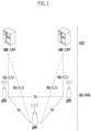
- FIG. 1 illustrates a structure of a wireless communication system to which the present disclosure may be applied.
- NG-RAN is configured with gNBs which provide a control plane (RRC) protocol end for a NG-RA(NG-Radio Access) user plane (i.e., a new AS(access stratum) sublayer/PDCP(Packet Data Convergence Protocol)/RLC(Radio Link Control)/MAC/PHY) and UE.
- RRC control plane
- the gNBs are interconnected through a Xn interface.
- the gNB in addition, is connected to an NGC(New Generation Core) through an NG interface.
- the gNB is connected to an AMF(Access and Mobility Management Function) through an N2 interface, and is connected to a UPF(User Plane Function) through an N3 interface.
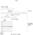
- FIG. 2 illustrates a frame structure in a wireless communication system to which the present disclosure may be applied.
- a NR system may support a plurality of numerologies.
- a numerology may be defined by a subcarrier spacing and a cyclic prefix (CP) overhead.
- CP cyclic prefix
- a plurality of subcarrier spacings may be derived by scaling a basic (reference) subcarrier spacing by an integer N (or, ⁇ ).
- N or, ⁇
- a used numerology may be selected independently from a frequency band.
- a variety of frame structures according to a plurality of numerologies may be supported in a NR system.
- a plurality of OFDM numerologies supported in a NR system may be defined as in the following Table 1.
- CP 0 15 Normal 1 30 Normal 2 60 Normal, Extended 3 120 Normal 4 240 Normal
- NR supports a plurality of numerologies (or subcarrier spacings (SCS)) for supporting a variety of 5G services. For example, when a SCS is 15kHz, a wide area in traditional cellular bands is supported, and when a SCS is 30kHz/60kHz, dense-urban, lower latency and a wider carrier bandwidth are supported, and when a SCS is 60kHz or higher, a bandwidth wider than 24.25GHz is supported to overcome a phase noise.
- numerologies or subcarrier spacings (SCS)
- NR frequency band is defined as a frequency range in two types (FR1, FR2).
- FR1, FR2 may be configured as in the following Table 2.
- FR2 may mean a millimeter wave (mmW).
- mmW millimeter wave
- ⁇ f max is 480-103 Hz and N f is 4096.
- One slot is configured with N symb slot consecutive OFDM symbols and N symb slot is determined according to CP.
- a start of a slot n s ⁇ in a subframe is temporally arranged with a start of an OFDM symbol n s ⁇ N symb slot in the same subframe. All terminals may not perform transmission and reception at the same time, which means that all OFDM symbols of a downlink slot or an uplink slot may not be used.
- Table 3 represents the number of OFDM symbols per slot (N symb slot ), the number of slots per radio frame (N slot frame, ⁇ ) and the number of slots per subframe (N slot subframe, ⁇ ) in a normal CP and Table 4 represents the number of OFDM symbols per slot, the number of slots per radio frame and the number of slots per subframe in an extended CP.
- Table 3 ⁇ N symb slot N slot frame, ⁇ N slot subframe, ⁇ 0 14 10 1 1 14 20 2 2 14 40 4 3 14 80 8 4 14 160 16
- Table 4 ⁇ N symb slot N slot frame, ⁇ N slot subframe, ⁇ 2 12 40 4
- a mini-slot may include 2, 4 or 7 symbols or more or less symbols.
- an antenna port a resource grid, a resource element, a resource block, a carrier part, etc. may be considered.
- the physical resources which may be considered in an NR system will be described in detail.
- an antenna port in relation to an antenna port, is defined so that a channel where a symbol in an antenna port is carried can be inferred from a channel where other symbol in the same antenna port is carried.
- a large-scale property of a channel where a symbol in one antenna port is carried may be inferred from a channel where a symbol in other antenna port is carried, it may be said that 2 antenna ports are in a QC/QCL(quasi co-located or quasi co-location) relationship.
- the large-scale property includes at least one of delay spread, doppler spread, frequency shift, average received power, received timing.
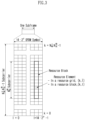
- FIG. 3 illustrates a resource grid in a wireless communication system to which the present disclosure may be applied.
- a resource grid is configured with N RB ⁇ N sc RB subcarriers in a frequency domain and one subframe is configured with 14 ⁇ 2 ⁇ OFDM symbols, but it is not limited thereto.
- a transmitted signal is described by OFDM symbols of 2 ⁇ N symb ( ⁇ ) and one or more resource grids configured with N RB ⁇ N sc RB subcarriers.
- N RB ⁇ ⁇ N RB max, ⁇ The N RB max, ⁇ represents a maximum transmission bandwidth, which may be different between an uplink and a downlink as well as between numerologies.
- one resource grid may be configured per ⁇ and antenna port p.
- Each element of a resource grid for ⁇ and an antenna port p is referred to as a resource element and is uniquely identified by an index pair (k,l').
- an index pair (k,l) is used.
- l 0,. . . , N symb ⁇ -1.
- a resource element (k,l') for ⁇ and an antenna port p corresponds to a complex value, a k,l' (p, ⁇ ) .
- indexes p and ⁇ may be dropped, whereupon a complex value may be a k,l' (p) or a k,l' .
- Point A plays a role as a common reference point of a resource block grid and is obtained as follows.
- Common resource blocks are numbered from 0 to the top in a frequency domain for a subcarrier spacing configuration ⁇ .
- the center of subcarrier 0 of common resource block 0 for a subcarrier spacing configuration ⁇ is identical to 'point A'.
- a relationship between a common resource block number n CRB ⁇ and a resource element (k,l) for a subcarrier spacing configuration ⁇ in a frequency domain is given as in the following Equation 1.
- n CRB ⁇ ⁇ k N sc RB ⁇
- Physical resource blocks are numbered from 0 to N BWP,i size, ⁇ -1 in a bandwidth part (BWP) and i is a number of a BWP.
- a relationship between a physical resource block n PRB and a common resource block n CRB in BWP i is given by the following Equation 2.
- N BWP,i start, ⁇ is a common resource block that a BWP starts relatively to common resource block 0.
- FIG. 4 illustrates a physical resource block in a wireless communication system to which the present disclosure may be applied.
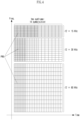
- FIG. 5 illustrates a slot structure in a wireless communication system to which the present disclosure may be applied.
- a slot includes a plurality of symbols in a time domain. For example, for a normal CP, one slot includes 7 symbols, but for an extended CP, one slot includes 6 symbols.
- a carrier includes a plurality of subcarriers in a frequency domain.
- An RB Resource Block
- a BWP(Bandwidth Part) is defined as a plurality of consecutive (physical) resource blocks in a frequency domain and may correspond to one numerology (e.g., an SCS, a CP length, etc.).
- a carrier may include a maximum N (e.g., 5) BWPs.
- a data communication may be performed through an activated BWP and only one BWP may be activated for one terminal.
- each element is referred to as a resource element (RE) and one complex symbol may be mapped.
- RE resource element
- a terminal operating in such a wideband CC may always operate turning on a radio frequency (FR) chip for the whole CC, terminal battery consumption may increase.
- FR radio frequency
- a different numerology e.g., a subcarrier spacing, etc.
- each terminal may have a different capability for the maximum bandwidth.
- a base station may indicate a terminal to operate only in a partial bandwidth, not in a full bandwidth of a wideband CC, and a corresponding partial bandwidth is defined as a bandwidth part (BWP) for convenience.
- a BWP may be configured with consecutive RBs on a frequency axis and may correspond to one numerology (e.g., a subcarrier spacing, a CP length, a slot/a mini-slot duration).
- a base station may configure a plurality of BWPs even in one CC configured to a terminal. For example, a BWP occupying a relatively small frequency domain may be configured in a PDCCH monitoring slot, and a PDSCH indicated by a PDCCH may be scheduled in a greater BWP.
- some terminals may be configured with other BWP for load balancing.
- some middle spectrums of a full bandwidth may be excluded and BWPs on both edges may be configured in the same slot.
- a base station may configure at least one DL/UL BWP to a terminal associated with a wideband CC.
- a base station may activate at least one DL/UL BWP of configured DL/UL BWP(s) at a specific time (by L1 signaling or MAC CE(Control Element) or RRC signaling, etc.).
- a base station may indicate switching to other configured DL/UL BWP (by L1 signaling or MAC CE or RRC signaling, etc.).
- a timer when a timer value is expired, it may be switched to a determined DL/UL BWP.
- an activated DL/UL BWP is defined as an active DL/UL BWP.
- a configuration on a DL/UL BWP may not be received when a terminal performs an initial access procedure or before a RRC connection is set up, so a DL/UL BWP which is assumed by a terminal under these situations is defined as an initial active DL/UL BWP.
- FIG. 6 illustrates physical channels used in a wireless communication system to which the present disclosure may be applied and a general signal transmission and reception method using them.
- a terminal receives information through a downlink from a base station and transmits information through an uplink to a base station.
- Information transmitted and received by a base station and a terminal includes data and a variety of control information and a variety of physical channels exist according to a type/a usage of information transmitted and received by them.
- a terminal When a terminal is turned on or newly enters a cell, it performs an initial cell search including synchronization with a base station or the like (S601).
- a terminal may synchronize with a base station by receiving a primary synchronization signal (PSS) and a secondary synchronization signal (SSS) from a base station and obtain information such as a cell identifier (ID), etc.
- PSS primary synchronization signal
- SSS secondary synchronization signal
- ID cell identifier
- a terminal may obtain broadcasting information in a cell by receiving a physical broadcast channel (PBCH) from a base station.
- PBCH physical broadcast channel
- a terminal may check out a downlink channel state by receiving a downlink reference signal (DL RS) at an initial cell search stage.
- DL RS downlink reference signal
- a terminal which completed an initial cell search may obtain more detailed system information by receiving a physical downlink control channel (PDCCH) and a physical downlink shared channel (PDSCH) according to information carried in the PDCCH (S602).
- PDCCH physical downlink control channel
- PDSCH physical downlink shared channel
- a terminal when a terminal accesses to a base station for the first time or does not have a radio resource for signal transmission, it may perform a random access (RACH) procedure to a base station (S603 to S606).
- RACH random access
- a terminal may transmit a specific sequence as a preamble through a physical random access channel (PRACH) (S603 and S605) and may receive a response message for a preamble through a PDCCH and a corresponding PDSCH (S604 and S606).
- PRACH physical random access channel
- a contention based RACH may additionally perform a contention resolution procedure.
- a terminal which performed the above-described procedure subsequently may perform PDCCH/PDSCH reception (S607) and PUSCH(Physical Uplink Shared Channel)/PUCCH(physical uplink control channel) transmission (S608) as a general uplink/downlink signal transmission procedure.
- a terminal receives downlink control information (DCI) through a PDCCH.
- DCI includes control information such as resource allocation information for a terminal and a format varies depending on its purpose of use.
- control information which is transmitted by a terminal to a base station through an uplink or is received by a terminal from a base station includes a downlink/uplink ACK/NACK(Acknowledgement/Non-Acknowledgement) signal, a CQI(Channel Quality Indicator), a PMI(Precoding Matrix Indicator), a RI(Rank Indicator), etc.
- a terminal may transmit control information of the above-described CQI/PMI/RI, etc. through a PUSCH and/or a PUCCH.
- Table 5 represents an example of a DCI format in an NR system.
- DCI Format Use 0_0 Scheduling of a PUSCH in one cell 0_1 Scheduling of one or multiple PUSCHs in one cell, or indication of cell group downlink feedback information to a UE 0_2 Scheduling of a PUSCH in one cell 1_0 Scheduling of a PDSCH in one DL cell 1_1 Scheduling of a PDSCH in one cell 1_2 Scheduling of a PDSCH in one cell
- DCI formats 0_0, 0_1 and 0_2 may include resource information (e.g., UL/SUL(Supplementary UL), frequency resource allocation, time resource allocation, frequency hopping, etc.), information related to a transport block(TB) (e.g., MCS(Modulation Coding and Scheme), a NDI(New Data Indicator), a RV(Redundancy Version), etc.), information related to a HARQ(Hybrid - Automatic Repeat and request) (e.g., a process number, a DAI(Downlink Assignment Index), PDSCH-HARQ feedback timing, etc.), information related to multiple antennas (e.g., DMRS sequence initialization information, an antenna port, a CSI request, etc.), power control information (e.g., PUSCH power control, etc.) related to scheduling of a PUSCH and control information included in each DCI format may be pre-defined.
- resource information e.g., UL/SUL(Sup
- DCI format 0_0 is used for scheduling of a PUSCH in one cell.
- Information included in DCI format 0_0 is CRC (cyclic redundancy check) scrambled by a C-RNTI(Cell Radio Network Temporary Identifier) or a CS-RNTI(Configured Scheduling RNTI) or a MCS-C-RNTI(Modulation Coding Scheme Cell RNTI) and transmitted.
- CRC cyclic redundancy check
- DCI format 0_1 is used to indicate scheduling of one or more PUSCHs or configure grant (CG) downlink feedback information to a terminal in one cell.
- Information included in DCI format 0_1 is CRC scrambled by a C-RNTI or a CS-RNTI or a SP-CSI-RNTI(Semi-Persistent CSI RNTI) or a MCS-C-RNTI and transmitted.
- DCI format 0_2 is used for scheduling of a PUSCH in one cell.
- Information included in DCI format 0_2 is CRC scrambled by a C-RNTI or a CS-RNTI or a SP-CSI-RNTI or a MCS-C-RNTI and transmitted.
- DCI formats 1_0, 1_1 and 1_2 may include resource information (e.g., frequency resource allocation, time resource allocation, VRB(virtual resource block)-PRB(physical resource block) mapping, etc.), information related to a transport block(TB)(e.g., MCS, NDI, RV, etc.), information related to a HARQ (e.g., a process number, DAI, PDSCH-HARQ feedback timing, etc.), information related to multiple antennas (e.g., an antenna port, a TCI(transmission configuration indicator), a SRS(sounding reference signal) request, etc.), information related to a PUCCH (e.g., PUCCH power control, a PUCCH resource indicator, etc.) related to scheduling of a PDSCH and control information included in each DCI format may be pre-defined.
- resource information e.g., frequency resource allocation, time resource allocation, VRB(virtual resource block)-PRB(physical resource block) mapping, etc.
- DCI format 1_0 is used for scheduling of a PDSCH in one DL cell.
- Information included in DCI format 1_0 is CRC scrambled by a C-RNTI or a CS-RNTI or a MCS-C-RNTI and transmitted.
- DCI format 1_1 is used for scheduling of a PDSCH in one cell.
- Information included in DCI format 1_1 is CRC scrambled by a C-RNTI or a CS-RNTI or a MCS-C-RNTI and transmitted.
- DCI format 1_2 is used for scheduling of a PDSCH in one cell.
- Information included in DCI format 1_2 is CRC scrambled by a C-RNTI or a CS-RNTI or a MCS-C-RNTI and transmitted.
- a coordinated multi point (CoMP) scheme refers to a scheme in which a plurality of base stations effectively control interference by exchanging (e.g., using an X2 interface) or utilizing channel information (e.g., RI/CQI/PMI/LI(layer indicator), etc.) fed back by a terminal and cooperatively transmitting to a terminal.
- a CoMP may be classified into joint transmission(JT), coordinated Scheduling(CS), coordinated Beamforming(CB), dynamic Point Selection(DPS), dynamic Point Blocking(DPB), etc.
- M-TRP transmission schemes that M TRPs transmit data to one terminal may be largely classified into i) eMBB M-TRP transmission, a scheme for improving a transfer rate, and ii) URLLC M-TRP transmission, a scheme for increasing a reception success rate and reducing latency.
- M-TRP transmission schemes may be classified into i) M-TRP transmission based on M-DCI(multiple DCI) that each TRP transmits different DCIs and ii) M-TRP transmission based on S-DCI(single DCI) that one TRP transmits DCI.
- M-DCI based M-TRP transmission all scheduling information on data transmitted by M TRPs should be delivered to a terminal through one DCI, it may be used in an environment of an ideal BackHaul (ideal BH) where dynamic cooperation between two TRPs is possible.
- scheme 3/4 is under discussion for standardization.
- scheme 4 means a scheme in which one TRP transmits a transport block(TB) in one slot and it has an effect to improve a probability of data reception through the same TB received from multiple TRPs in multiple slots.
- scheme 3 means a scheme in which one TRP transmits a TB through consecutive number of OFDM symbols (i.e., a symbol group) and TRPs may be configured to transmit the same TB through a different symbol group in one slot.
- UE may recognize PUSCH (or PUCCH) scheduled by DCI received in different control resource sets(CORESETs)(or CORESETs belonging to different CORESET groups) as PUSCH (or PUCCH) transmitted to different TRPs or may recognize PDSCH (or PDCCH) from different TRPs.
- the below-described method for UL transmission e.g., PUSCH/PUCCH
- PUSCH/PUCCH PUSCH/PUCCH
- MTRP-URLLC may mean that a M TRPs transmit the same transport block(TB) by using different layer/time/frequency.
- a UE configured with a MTRP-URLLC transmission scheme receives an indication on multiple TCI state(s) through DCI and may assume that data received by using a QCL RS of each TCI state are the same TB.
- MTRP-eMBB may mean that M TRPs transmit different TBs by using different layer/time/frequency.
- a UE configured with a MTRP-eMBB transmission scheme receives an indication on multiple TCI state(s) through DCI and may assume that data received by using a QCL RS of each TCI state are different TBs.
- UE may decide/determine whether the corresponding M-TRP transmission is URLLC transmission or eMBB transmission.
- CRC masking of DCI received by UE is performed by using a RNTI configured for MTRP-URLLC, it may correspond to URLLC transmission
- CRC masking of DCI is performed by using a RNTI configured for MTRP-eMBB, it may correspond to eMBB transmission.
- a CORESET group ID described/mentioned in the present disclosure may mean an index/identification information (e.g., an ID, etc.) for distinguishing a CORESET for each TRP/panel.
- a CORESET group may be a group/union of CORESET distinguished by an index/identification information (e.g., an ID)/the CORESET group ID, etc. for distinguishing a CORESET for each TRP/panel.
- a CORESET group ID may be specific index information defined in a CORESET configuration.
- a CORESET group may be configured/indicated/defined by an index defined in a CORESET configuration for each CORESET.
- a CORESET group ID may mean an index/identification information/an indicator, etc. for distinguishment/identification between CORESETs configured/associated with each TRP/panel.
- a CORESET group ID described/mentioned in the present disclosure may be expressed by being substituted with a specific index/specific identification information/a specific indicator for distinguishment/identification between CORESETs configured/associated with each TRP/panel.
- the CORESET group ID i.e., a specific index/specific identification information/a specific indicator for distinguishment/identification between CORESETs configured/associated with each TRP/panel may be configured/indicated to a terminal through higher layer signaling (e.g., RRC signaling)/L2 signaling (e.g., MAC-CE)/L1 signaling (e.g., DCI), etc.
- RRC signaling e.g., RRC signaling
- L2 signaling e.g., MAC-CE
- L1 signaling e.g., DCI
- uplink control information e.g., CSI, HARQ-A/N(ACK/NACK), SR(scheduling request)
- uplink physical channel resources e.g., PUCCH/PRACH/SRS resources
- HARQ A/N(process/retransmission) for PDSCH/PUSCH, etc. scheduled per each TRP/panel may be managed per corresponding CORESET group (i.e., per TRP/panel belonging to the same CORESET group).
- ControlResourceSet information element is used to configure a time/frequency control resource set (CORESET).
- the control resource set (CORESET) may be related to detection and reception of downlink control information.
- the ControlResourceSet IE may include a CORESET-related ID (e.g., controlResourceSetID)/an index of a CORESET pool for a CORESET (e.g., CORESETPoolIndex)/a time/frequency resource configuration of a CORESET/TCI information related to a CORESET, etc.
- an index of a CORESET pool (e.g., CORESETPoolIndex) may be configured as 0 or 1.
- a CORESET group may correspond to a CORESET pool and a CORESET group ID may correspond to a CORESET pool index (e.g., CORESETPoolIndex).
- NCJT Non-coherent joint transmission
- TP transmission points
- DMRS Demodulation Multiplexing Reference Signal
- a TP delivers data scheduling information through DCI to a terminal receiving NCJT.
- a scheme in which each TP participating in NCJT delivers scheduling information on data transmitted by itself through DCI is referred to as 'multi DCI based NCJT'.
- UE receives N DCI and N PDSCHs from N TPs.
- a scheme in which one representative TP delivers scheduling information on data transmitted by itself and data transmitted by a different TP (i.e., a TP participating in NCJT) through one DCI is referred to as 'single DCI based NCJT'.
- N TPs transmit one PDSCH, but each TP transmits only some layers of multiple layers included in one PDSCH. For example, when 4-layer data is transmitted, TP 1 may transmit 2 layers and TP 2 may transmit 2 remaining layers to UE.
- NCJT partially overlapped NCJT
- NCJT may be classified into fully overlapped NCJT that time frequency resources transmitted by each TP are fully overlapped and partially overlapped NCJT that only some time frequency resources are overlapped.
- data of both of TP 1 and TP 2 are transmitted in some time frequency resources and data of only one TP of TP 1 or TP 2 is transmitted in remaining time frequency resources.
- FIG. 7 illustrates a method of multiple TRPs transmission in a wireless communication system to which the present disclosure may be applied.
- a layer group may mean a predetermined layer set including one or more layers.
- the amount of transmitted resources increases due to the number of a plurality of layers and thereby a robust channel coding with a low coding rate may be used for a TB, and additionally, because a plurality of TRPs have different channels, it may be expected to improve reliability of a received signal based on a diversity gain.
- FIG. 15(b) an example that different CWs are transmitted through layer groups corresponding to different TRPs is shown.
- a TB corresponding to CW #1 and CW #2 in the drawing is identical to each other.
- CW #1 and CW #2 mean that the same TB is respectively transformed through channel coding, etc. into different CWs by different TRPs. Accordingly, it may be considered as an example that the same TB is repetitively transmitted.
- FIG. 15(b) it may have a disadvantage that a code rate corresponding to a TB is higher compared to FIG. 15 (a) .
- it has an advantage that it may adjust a code rate by indicating a different RV (redundancy version) value or may adjust a modulation order of each CW for encoded bits generated from the same TB according to a channel environment.
- RV redundancy version
- probability of data reception of a terminal may be improved as the same TB is repetitively transmitted through a different layer group and each layer group is transmitted by a different TRP/panel. It is referred to as a SDM (Spatial Division Multiplexing) based M-TRP URLLC transmission method. Layers belonging to different layer groups are respectively transmitted through DMRS ports belonging to different DMRS CDM groups.
- the above-described contents related to multiple TRPs are described based on an SDM (spatial division multiplexing) method using different layers, but it may be naturally extended and applied to a FDM (frequency division multiplexing) method based on a different frequency domain resource (e.g., RB/PRB (set), etc.) and/or a TDM (time division multiplexing) method based on a different time domain resource (e.g., a slot, a symbol, a sub-symbol, etc.).
- FDM frequency division multiplexing
- a different frequency domain resource e.g., RB/PRB (set), etc.
- TDM time division multiplexing
- FIG. 8 is a diagram illustrating a downlink transmission and reception operation in a wireless communication system to which the present disclosure can be applied.
- a base station schedules downlink transmission such as a frequency/time resource, a transport layer, a downlink precoder, an MCS, etc. (S1401).
- a base station can determine a beam for PDSCH transmission to a UE through the operations described above.
- a UE receives DCI for downlink scheduling (i.e., including scheduling information of a PDSCH) from a base station on a PDCCH (S1402).
- DCI for downlink scheduling i.e., including scheduling information of a PDSCH
- DCI format 1_0, 1_1, or 1_2 may be used for downlink scheduling, and in particular, DCI format 1_1 includes the following information: an identifier for a DCI format, a bandwidth part indicator, a frequency domain resource assignment, a time domain resource assignment, a PRB bundling size indicator, a rate matching indicator, a ZP CSI-RS trigger, antenna port(s), a transmission configuration indication (TCI), an SRS request, a DMRS (Demodulation Reference Signal) sequence initialization
- a number of DMRS ports may be scheduled according to each state indicated in an antenna port(s) field, and also single-user (SU)/multi-user (MU) user transmission scheduling is possible.
- SU single-user
- MU multi-user
- a TCI field is composed of 3 bits, and a QCL for a DMRS is dynamically indicated by indicating up to 8 TCI states according to a TCI field value.
- a UE receives downlink data from a base station on a PDSCH (S1403).
- a UE When a UE detects a PDCCH including DCI formats 1_0, 1_1, and 1_2, it decodes a PDSCH according to indications by corresponding DCI.
- a DMRS configuration type may be configured for the UE by a higher layer parameter 'dmrs-Type', and a DMRS type is used to receive a PDSCH.
- a maximum number of front-loaded DMRA symbols for the PDSCH may be configured for a terminal by a higher layer parameter 'maxLength'.
- DMRS configuration type 1 For DMRS configuration type 1, if a single codeword is scheduled for a UE and an antenna port mapped to an index of ⁇ 2, 9, 10, 11 or 30 ⁇ is indicated or if a single codeword is scheduled and an antenna port mapped to an index of ⁇ 2, 9, 10, 11 or 12 ⁇ or ⁇ 2, 9, 10, 11, 30 or 31 ⁇ is indicated, or if two codewords are scheduled, the UE assumes that all remaining orthogonal antenna ports are not associated with PDSCH transmission to another UE.
- DMRS configuration type 1 if a single codeword is scheduled for a UE and an antenna port mapped to an index of ⁇ 2, 10 or 23 ⁇ is indicated, or if a single codeword is scheduled and an antenna port mapped to an index of ⁇ 2, 10, 23 or 24 ⁇ or ⁇ 2, 10, 23 or 58 ⁇ is indicated, or if two codewords are scheduled for a UE, the UE assumes that all remaining orthogonal antenna ports are not associated with PDSCH transmission to another UE.
- a precoding unit (precoding granularity) P' may be assumed to be a contiguous resource block in a frequency domain.
- P' may correspond to one of ⁇ 2, 4, wideband ⁇ .
- P' is determined to be wideband, a UE does not expect to be scheduled with non-contiguous PRBs, and a UE can assume that the same precoding is applied to allocated resources.
- a precoding resource block group PRG is divided into P' consecutive PRBs.
- An actual number of consecutive PRBs in each PRG may be one or more.
- a UE may assume that the same precoding is applied to consecutive downlink PRBs within a PRG.
- the UE In order for a UE to determine a modulation order, a target code rate, and a transport block size in a PDSCH, the UE first reads a 5-bit MCD field in DCI and determines a modulation order and a target code rate. Then, the UE reads a redundancy version field in the DCI and determines a redundancy version. Then, a UE determines a transport block size using a number of layers and a total number of allocated PRBs before rate matching.
- Downlink SPS combines persistent scheduling through higher layer signaling (RRC, etc.) and dynamic scheduling through lower layer signaling (DCI, etc.). Persistent scheduling is used for periodic resource allocation for the first transmission of a transport block (TB). Dynamic scheduling is used to allocate resources for retransmission when retransmission is required.
- RRC higher layer signaling
- DCI lower layer signaling
- persistent scheduling through higher layer signaling may be transmitted before dynamic scheduling (S1402) of lower layer signaling (DCI, etc.).
- a UE can report support of SPS to a base station using a downlinkSPS flag in UE capability information.
- RRC signaling and physical layer signaling on a PDCCH are used in combination.
- RRC signaling e.g., SPS-Config IE
- SPS-Config IE provides a subset of resource allocation information, and additional information is provided by a PDCCH.
- a PDCCH is used as a trigger for activation/release.
- SPS-Config IE is used to configure downlink semi-persistent transmission. Multiple downlink SPS configurations can be configured within one BWP of a serving cell.
- the periodicity represents a period of downlink SPS, which means a time interval between consecutive persistent resource allocations.
- the periodicityExt is used to calculate a period of downlink SPS, and if this parameter does not exist, the periodicity is ignored.
- An SPS period supports different values depending on the configured subcarrier spacing.
- the nrofHARQ-Processes indicates a number of a HARQ process configured for downlink SPS.
- a HARQ process identifier is specified within DCI associated with each resource allocation.
- a HARQ process identifier is determined based on a value of the nrofHARQ-Processes and a value of the periodicity.
- the n1PUCCH-AN indicates a HARQ resource of a PUCCH for downlink SPS.
- An actual PUCCH-Resource is configured according to a value of the n1PUCCH-AN, and based on this, a PUCCH resource for transmitting a HARQ ACK to a base station is identified.
- the mcs-Table indicates an MCS table used by a UE for downlink SPS.
- the pdsch-AggregationFactor represents a repetition number of an SPS PDSCH and can have one value among ⁇ 1,2,4,8 ⁇ . If this field does not exist, a UE applies the pdsch-AggregationFactor of PDSCH-Config. That is, a UE repeatedly receives the same downlink data/transport block (TB) in consecutive slots.
- the same symbol allocation is applied over consecutive slots according to the configured repetition number (pdsch-AggregationFactor). That is, a UE repeatedly receives a downlink TB from the same symbol over several consecutive slots according to the configured repetition number.
- a PDSCH is limited to a single transmission layer.
- a time interval for reception according to the number of repetitions is not greater than a period interval derived by a period obtained from SPS-config.
- a redundancy version (rv_id) is determined differently for each TO of a TB. For a PDSCH scheduled without corresponding PDCCH transmission using SPS-config, a redundancy version indicated by DCI is assumed to be 0.
- the UE When a UE configured with SPS in a higher layer receives DCI on a PDCCH, the UE first verifies whether a downlink SPS assignment PDCCH is valid.
- a UE determines that a downlink SPS assignment PDCCH is valid for scheduling activation/scheduling release.
- a UE verifies whether a DCI format is valid as follows.
- Table 7 illustrates fields for verifying single downlink SPS scheduling activation when a UE is provided with a single SPS PDSCH configuration in a downlink BWP of a scheduled cell.
- DCI format 1_1 HARQ process number set to all '0's Redundancy version
- Table 8 illustrates fields for verifying single downlink SPS scheduling release when a UE is provided with a single SPS PDSCH configuration in a downlink BWP of a scheduled cell.
- DCI format 1_0/1_1/1_2 HARQ process number set to all '0's Redundancy version set to all '0's Modulation and coding scheme set to all '1's Frequency domain resource assignment - set to all '0's for FDRA Type 0 or for dynamicSwitch - set to all '1's for FDRA Type 1
- a UE When a UE is provided with one or more SPS PDSCH configurations, when a HARQ process number field in a DCI format indicated to activate an SPS PDSCH configuration with the same value as an index (i.e., sps-ConfigIndex) of a specific configuration among one or more SPS PDSCH configurations, and when a redundancy version (RV) field of a DCI format is set as shown in Table 7 above, verification of a DCI format for SPS PDSCH activation is achieved.
- an index i.e., sps-ConfigIndex
- a HARQ process number field in a DCI format indicates to release an SPS PDSCH with the same value as an index (i.e., sps-ConfigDeactivationStateList or sps-ConfigIndex) of a specific configuration among one or more SPS PDSCH configurations, and when RV, MCS (modulation and coding scheme), and FDRA (frequency domain resource assignment) fields of a DCI format are all set as shown in Table 8, verification of a DCI format for SPS PDSCH release is achieved.
- an index i.e., sps-ConfigDeactivationStateList or sps-ConfigIndex
- a UE may be configured to repeatedly receive a PDSCH.
- a UE repeatedly receives the same downlink data/transport block (TB) in consecutive slots.
- TB downlink data/transport block
- the number of repetitions for a downlink TB may have one of ⁇ 2, 4, 8 ⁇ values. That is, the same TB can be transmitted in 2 consecutive slots, 4 slots, or 8 slots. There is one TB transmission (i.e., one transmission occasion (TO)) within each slot. If the number of repetitions is not set (i.e., if there is no pdsch-AggregationFactor), a UE applies a value of 1.
- a UE When a UE receives a PDSCH scheduled by DCI, if the UE is configured with repetition number > 1 (e.g., pdsch-AggregationFactor > 1), the same symbol allocation is applied across consecutive slots according to the configured number of repetitions. That is, a UE repeatedly receives a downlink TB from the same symbol over several consecutive slots according to the configured repetition number.
- repetition number > 1 e.g., pdsch-AggregationFactor > 1
- a UE repeatedly receives a downlink TB from the same symbol over several consecutive slots according to the configured repetition number.
- a redundancy version (rv_id) is determined differently for each TO of a TB. That is, based on a redundancy version indicated by DCI scheduling a PDSCH, a redundancy version applied to the n-th TO is determined according to Table 9 below.
- Table 9 illustrates aredundancy version applied when pdsch-AggregationFactor exists.
- FIG. 9 is a diagram illustrating an uplink transmission and reception operation in a wireless communication system to which the present disclosure can be applied.
- a base station schedules uplink transmission such as a frequency/time resource, a transport layer, an uplink precoder, an MCS, etc. (S1501).
- a base station can determine a beam for PUSCH transmission to a UE through the operations described above.
- a UE receives DCI for uplink scheduling (i.e., including scheduling information of a PUSCH) from a base station on a PDCCH (S1502).
- DCI format 0_0, 0_1, or 0_2 may be used for uplink scheduling, and in particular, DCI format 0_1 includes the following information: an identifier for a DCI format, a UL/SUL (supplementary uplink) indicator, a bandwidth part indicator, a frequency domain resource assignment, a time domain resource assignment, a frequency hopping flag, a modulation and coding scheme (MCS), an SRS resource indicator (SRI), precoding information and number of layers, antenna port(s), an SRS request, a DMRS sequence initialization, a UL-SCH (Uplink Shared Channel) indicator
- MCS modulation and coding scheme
- SRI SRS resource indicator
- SRS resources configured in an SRS resource set associated with the higher upper layer parameter 'usage' may be indicated by an SRS resource indicator field.
- the 'spatialRelationInfo' can be configured for each SRS resource, and its value can be one of ⁇ CRI, SSB, SRI ⁇ .
- a UE transmits uplink data to a base station on a PUSCH (S1503).
- a UE When a UE detects a PDCCH including DCI formats 0_0, 0_1, and 0_2, it transmits a PUSCH according to indications by corresponding DCI.
- codebook-based transmission Two transmission methods are supported for PUSCH transmission: codebook-based transmission and non-codebook-based transmission:
- a PUSCH may be scheduled in DCI format 0_0, DCI format 0_1, DCI format 0_2, or semi-statically. If this PUSCH is scheduled by DCI format 0_1, a UE determines a PUSCH transmission precoder based on an SRI, a TPMI (Transmit Precoding Matrix Indicator), and a transmission rank from DCI, as given by an SRS resource indicator field and a precoding information and number of layers field.
- a TPMI is used to indicate a precoder to be applied across antenna ports, and corresponds to an SRS resource selected by an SRI when multiple SRS resources are configured.
- a TPMI is used to indicate a precoder to be applied across antenna ports and corresponds to that single SRS resource.
- a transmission precoder is selected from an uplink codebook having the same number of antenna ports as the higher layer parameter 'nrofSRS-Ports'.
- the UE is configured with at least one SRS resource.
- An SRI indicated in slot n is associated with the most recent transmission of an SRS resource identified by the SRI, where the SRS resource precedes a PDCCH carrying the SRI (i.e., slot n).
- a PUSCH may be scheduled in DCI format 0_0, DCI format 0_1, or semi-statically.
- a UE can determine a PUSCH precoder and a transmission rank based on a wideband SRI, where, the SRI is given by an SRS resource indicator in DCI or by the higher layer parameter 'srs-ResourceIndicator'.
- a UE uses one or multiple SRS resources for SRS transmission, where the number of SRS resources can be configured for simultaneous transmission within the same RB based on a UE capability. Only one SRS port is configured for each SRS resource.
- SRS resource Only one SRS resource can be configured with the higher layer parameter 'usage' set to 'nonCodebook'.
- the maximum number of SRS resources that can be configured for non-codebook based uplink transmission is 4.
- An SRI indicated in slot n is associated with the most recent transmission of an SRS resource identified by the SRI, where the SRS transmission precedes a PDCCH carrying the SRI (i.e., slot n).
- PUSCH configured grant is divided into CG (configured grant) Type 1 and CG Type 2.
- CG Type 1 resource allocation is completely configured or released using RRC signaling.
- a UE When CG Type 1 is configured, a UE is allocated a resource set that can periodically transmit a PUSCH. A PDCCH is required only when retransmission is necessary.
- CG Type 1 PUSCH transmission is semi-statically configured to operate when receiving the higher layer parameter configuredGrantConfig including rrc-ConfiguredUplinkGrant without detection of a UL grant in DCI.
- a UE can perform PUSCH transmission according to the configured CG Type 1 until additional RRC signaling is reconfigured to the UE.
- CG Type 2 resource allocation is partially configured using RRC signaling, and activation/deactivation is indicated using PDCCH transmission. Since a PDCCH also provides time and frequency resource allocation, resource allocation may vary each time it is activated.
- CG Type 2 PUSCH transmission is scheduled semi-persistently by a UL grant in valid activation DCI after receipt of the higher layer parameter configuredGrantConfig that does not include rrc-ConfiguredUplinkGrant.
- higher layer signaling (RRC, etc.) for a PUSCH configured grant may be transmitted before lower layer signaling (DCI, etc.) for uplink scheduling.
- One or more CG configurations of CG Type 1 and/or CG Type 2 may be activated simultaneously on an activated BWP of a serving cell.
- parameters for PUSCH transmission may be provided by configuredGrantConfig.
- configuredGrantConfig IE is used to configure uplink transmission without dynamic grant by DCI.
- An actual uplink grant may be configured by RRC (CG Type 1) or provided through a PDCCH (by CS-RNTI) (CG Type 2).
- Multiple CG configurations can be configured within one BWP of a serving cell.
- the periodicity represents a period for uplink CG transmission, which means a time interval between consecutive continuous resource allocations.
- the periodicityExt is used to calculate a period of a uplink CG, and if this parameter does not exist, the periodicity is ignored. Values supported for an uplink CG period vary depending on the configured subcarrier spacing.
- the nrofHARQ-Processes indicates a number of a HARQ process configured for an uplink CG.
- a HARQ process identifier is specified within DCI associated with each resource allocation.
- an identifier of a HARQ process is determined based on a value of the nrofHARQ-Processes and a value of the periodicity.
- the repK represents the number of repetitions. That is, it indicates a repetition level for each PUSCH transmission.
- the repK can have one of the following values: ⁇ 1,2,4,8 ⁇ .
- PUSCH repetition type B is applied, otherwise, PUSCH repetition type A is applied.
- a PUSCH repetition type is determined by a UL grant of DCI. According to the configured PUSCH repetition type A or B, a UE transmits an uplink TB repeatedly as many times as the configured repetition number.
- the repK-RV represents a redundancy version sequence.
- the repK-RV is configured when a repetition is used (i.e., repK is set to one of ⁇ 2,4,8 ⁇ ).
- the resourceAllocation indicates a configuration of bitmap-based resource allocation type 0 or resource indication value (RIV)-based resource allocation type 1.
- the mcs-Table indicates an MCS table used by a UE for a PUSCH in which a transform precoding is not used
- the mcs-TableTransformPrecoder indicates an MCS table used by a UE for a PUSCH in which a transform precoding is used.
- the transformPrecoder indicates whether a transform precoding is enabled for a PUSCH.
- the rrc-ConfiguredUplinkGrant is a configuration for CG Type 1 transmission. If this field does not exist, a UE uses an UL grant configured by DCI with a CS-RNTI (i.e., CG Type 2).
- the timeDomainAllocation indicates a start symbol and a length of a PUSCH and a PUSCH mapping type.
- the timeDomainOffset represents an offset related to a reference SFN (system frame number) indicated by the timeReferenceSFN.
- the timeReferenceSFN indicates an SFN used to determine an offset of a resource in a time domain.
- a UE uses an SFN closest to a number indicated before receiving a configured grant configuration, and if this field does not exist, a reference SFN is 0.
- the UE When a UE configured a configured grant by a higher layer receives DCI on a PDCCH, the UE first verifies whether the configured UL grant Type 2 PDDCH is valid.
- a UE determines that the configured UL grant Type 2 PDDCH for scheduling activation/scheduling release is valid.
- a UE verifies whether a DCI format is valid as follows.
- Table 11 illustrates fields for verification of single UL grant Type 2 scheduling activation when a UE is provided with a single UL grant Type 2 configuration in an uplink BWP of a scheduled cell.
- Table 12 illustrates fields for verification of single UL grant Type 2 scheduling release when a UE is provided with a single UL grant Type 2 configuration in an uplink BWP of a scheduled cell.
- DCI format 0_0/0_1/0_2 HARQ process number set to all '0's Redundancy version set to all '0's Modulation and coding scheme set to all '1's Frequency domain resource assignment - set to all '0's for FDRA Type 2 with ⁇ 1 - set to all '1's, otherwise
- a HARQ process number field in a DCI format indicates UL grant Type 2 PUSCH configuration activation with a value equal to the index (i.e., ConfiguredGrantConfigIndex) of a specific configuration among one or more UL grant Type 2 PUSCH configurations, and when a RV (redundancy version) field of a DCI format is configured as shown in Table 11 above, verification of the DCI format for UL grant Type 2 PUSCH activation is achieved.
- a HARQ process number field in a DCI format indicates release of the UL grant Type 2 PUSCH configuration with a value equal to an index of a specific configuration among one or more UL grant Type 2 PUSCH configurations (i.e., ConfiguredGrantConfigType2DeactivationStateList or ConfiguredGrantConfigIndex), and when RV, MCS (modulation and coding scheme), and FDRA (frequency domain resource assignment) fields of a DCI format are all set as shown in Table 12, verification of a DCI format for UL grant Type 2 PUSCH release is achieved.
- ConfiguredGrantConfigType2DeactivationStateList or ConfiguredGrantConfigIndex when RV, MCS (modulation and coding scheme), and FDRA (frequency domain resource assignment) fields of a DCI format are all set as shown in Table 12, verification of a DCI format for UL grant Type 2 PUSCH release is achieved.
- a 'Time domain resource assignment' field value of a UL grant in DCI provides a row value of a resource allocation table.
- Each row of a resource allocation table defines parameters for time domain resource allocation, specifically, a slot offset (K_2) and a start and length indicator (SLIV) (or directly a starting symbol (S) and an allocation length (L)), a PUSCH mapping type, and a repetition number (when numberOfRepetitions is present) to be applied to PUSCH transmission are defined.
- a resource allocation table may be configured by the higher layer parameter PUSCH-TimeDomainResourceAllocationList, or may be a predefined table.
- the PUSCH-TimeDomainResourceAllocationList (i.e., resource allocation table) includes one or more PUSCH-TimeDomainResourceAllocation IEs.
- PUSCH-TimeDomainResourceAllocation IE is used to establish a time domain relationship between a PDCCH and a PUSCH, and configure parameters for the above-described time domain resource allocation.
- a 'Time domain resource assignment' field in DCI a value of 0 indicates the first element (TimeDomainResourceAllocation) in the list (i.e., the first row of the resource allocation table), a value of 1 indicates the second element in the list, and so on.
- a UE may be configured to transmit a PUSCH repeatedly. In this case, a UE repeatedly transmits the same uplink data/transport block (TB).
- TB uplink data/transport block
- a PUSCH repetition transmission method can be divided into PUSCH repetition type A and PUSCH repetition type B.
- a PUSCH repetition type i.e., pusch-RepTypeIndicatorDCI-0-1 or pusch-RepTypeIndicatorDCI-0-2
- PUSCH repetition Type B i.e., 'pusch-RepTypeB'
- a UE applies the PUSCH repetition Type A procedure when determining time domain resource allocation for a PUSCH scheduled by a PDCCH.
- PUSCH repetition type A transmission refers to a slot level PUSCH repetition in which the same uplink data (TB or CSI) is transmitted repeatedly in consecutive slots, including only one repetition in one slot.
- a start symbol S of a PUSCH relative to a start of a slot, and a consecutive symbols L counted from a symbol S allocated for a PUSCH, are determined from a start and length indicator (SLIV) of an indicated row of a resource allocation table.
- a repetition number K is determined by the repetition number configuration (i.e., numberOfRepetitions). Otherwise, a number of repetitions for an uplink TB (e.g., higher layer parameter pusch-AggregationFactor) may have one of ⁇ 2, 4, 8 ⁇ values. That is, the same TB can be transmitted in 2 consecutive slots, 4 slots, or 8 slots. There is one TB transmission (i.e., one TO) in each slot. If a number of repetitions is not configured (i.e., if there is no pusch-AggregationFactor), a UE applies a value of 1.
- a UE transmits a PUSCH scheduled by DCI
- a repetition count > 1 e.g., pusch-AggregationFactor > 1
- the same symbol allocation is applied across consecutive slots according to the configured number of repetitions. That is, a UE repeatedly transmits an uplink TB in the same symbol over several consecutive slots according to the configured repetition number.
- a PUSCH is limited to a single transmission layer.
- a redundancy version (rv_id) is determined differently for each TO of a TB. That is, based on a redundancy version indicated by DCI scheduling a PUSCH, a redundancy version applied to the n-th TO is determined according to Table 13 below.
- Table 13 illustrates a redundancy version for PUSCH transmission.
- rv_id indicated by the DCI scheduling the PUSCH rv_id to be applied to nth transmission occasion (repetition Type A) or nth actual repetition (repetition Type B)
- n mod 4 0
- n mod 4 1
- n mod 4 2
- 3 0 0 2 3 1 2 2 3 1 0 3 3 1 0 2 1 1 0 2 3
- intra-slot frequency hopping or inter-slot frequency hopping can be configured.
- frequency hopping occurs at a slot boundary.
- intra-slot frequency hopping the number of symbols in the first hop and the number of symbols in the second hop are configured by the base station, and frequency hopping is performed at the configured symbol boundary.
- PUSCH repetition type B transmission refers to a symbol level PUSCH repetition in which the same uplink data (TB or CSI) is repeatedly transmitted, including two or more repetitions in one slot.
- a start symbol S of a PUSCH relative to a start of a slot, and a consecutive symbols L counted from a symbol S allocated for a PUSCH are respectively determined by a start symbol (i.e., startSymbol) and length (i.e., length) of an indicated row of a resource allocation table.
- K_2 slot offset
- a nominal number of repetitions means a number of repetitions indicated by RRC signaling, etc. For example, if one nominal repetition passes (including) a slot boundary (or DL/UL switching point), the one nominal repetition may be divided into two before and after the slot boundary (or DL/UL switching point), therefore an actual number of repetitions may be greater than the nominal number of repetitions.
- a redundancy version applied on the n-th actual repetition (including the case where actual repetition is omitted) is determined according to Table 13 described above.
- inter-repetition frequency hopping or inter-slot frequency hopping can be configured.
- frequency hopping is applied per nominal number of repetitions.
- frequency hopping occurs at a slot boundary.
- node(s) and UE(s) in a wireless communication network are becoming more intelligent/advanced.
- various network/base station decision parameter values e.g., transmission/reception power of each base station, transmission power of each UE, precoder/beam of base station/UE, time/frequency resource allocation for each UE, duplex method of each base station, etc.
- environmental parameters e.g., distribution/location of base stations, distribution/location/material of buildings/furniture, etc., location/movement direction/speed of UEs, climate information, etc.
- FIG. 10 illustrates a classification of artificial intelligence.
- AI artificial intelligence
- Machine Learning refers to a technology in which machines learn patterns for decision-making from data on their own without explicitly programming rules.
- Deep Learning is an artificial neural network-based model that allows a machine to perform feature extraction and decision from unstructured data at once.
- the algorithm relies on a multi-layer network of interconnected nodes for feature extraction and transformation, inspired by the biological nervous system, or Neural Network.
- Common deep learning network architectures include deep neural networks (DNNs), recurrent neural networks (RNNs), and convolutional neural networks (CNNs).
- AI can be narrowly referred to as artificial intelligence based on deep learning, but is not limited to this in the present disclosure. That is, in the present disclosure, AI (or AI/ML) may collectively refer to automation technologies applied to intelligent machines (e.g., UE, RAN, network nodes, etc.) that can perform tasks like humans.
- intelligent machines e.g., UE, RAN, network nodes, etc.
- AI (or AI/ML) can be classified according to various criteria as follows.
- Offline learning follows a sequential procedure of database collection, learning, and prediction.
- collection and learning can be performed offline, and the completed program can be installed in the field and used for prediction work.
- the system does not learn incrementally, the learning is performed using all available collected data and applied to the system without further learning. If learning about new data is necessary, learning can begin again using all new data.
- centralized learning training data collected from a plurality of different nodes is reported to a centralized node, all data resources/storage/learning (e.g., supervised learning, unsupervised learning, reinforcement learning, etc.) are performed in one centralized node.
- all data resources/storage/learning e.g., supervised learning, unsupervised learning, reinforcement learning, etc.
- Federated learning is a collective model built on data that exists across distributed data owners. Instead of collecting data into a model, AI/ML models are imported into a data source, allowing local nodes/individual devices to collect data and train their own copies of the model, eliminating the need to report the source data to a central node. In federated learning, the parameters/weights of an AI/ML model can be sent back to the centralized node to support general model training. Federated learning has advantages in terms of increased computation speed and information security. In other words, the process of uploading personal data to the central server is unnecessary, preventing leakage and misuse of personal information.
- Distributed learning refers to the concept in which machine learning processes are scaled and distributed across a cluster of nodes. Training models are split and shared across multiple nodes operating simultaneously to speed up model training.
- Supervised learning is a machine learning task that aims to learn a mapping function from input to output, given a labeled data set.
- the input data is called training data and has known labels or results.
- An example of supervised learning is as follows.
- Supervised learning can be further grouped into regression and classification problems, where classification is predicting a label and regression is predicting a quantity.
- Unsupervised learning is a machine learning task that aims to learn features that describe hidden structures in unlabeled data. The input data is not labeled and there are no known results.
- Some examples of unsupervised learning include K-means clustering, Principal Component Analysis (PCA), nonlinear Independent Component Analysis (ICA), and Long-Short-Term Memory (LSTM).
- RL reinforcement learning
- the agent aims to optimize long-term goals by interacting with the environment based on a trial and error process, and is goal-oriented learning based on interaction with the environment.
- An example of the RL algorithm is as follows.
- reinforcement learning can be grouped into model-based reinforcement learning and model-free reinforcement learning as follows.
- RL algorithm can also be classified into value-based RL vs. policy-based RL, policy-based RL vs. non-policy RL, etc.
- FIG. 11 illustrates a feed-forward neural network
- a feed-forward neural network is composed of an input layer, a hidden layer, and an output layer.
- FFNN In FFNN, information is transmitted only from the input layer to the output layer, and if there is a hidden layer, it passes through it.
- FIG. 12 illustrates a recurrent neural network
- a recurrent neural network is a type of artificial neural network in which hidden nodes are connected to directed edges to form a directed cycle. This model is suitable for processing data that appears sequentially, such as voice and text.
- A represents a neural network
- xt represents an input value
- ht represents an output value
- ht may refer to a state value representing the current state based on time
- ht-1 may represent a previous state value
- LSTM Long Short-Term Memory
- LSTM Long Short-Term Memory
- FIG. 13 illustrates a convolutional neural network
- CNN Convolutional neural network
- FIG. 14 illustrates an auto encoder
- Auto encoder refers to a neural network that receives a feature vector x (x1, x2, x3, ...) as input and outputs the same or similar vector x' (x'1, x'2, x'3, ...)'.
- Auto encoder has the same characteristics as the input node and output node. Since the auto encoder reconstructs the input, the output can be referred to as reconstruction. Additionally, auto encoder is a type of unsupervised learning.
- the loss function of the auto encoder illustrated in FIG. 14 is calculated based on the difference between input and output, and based on this, the degree of input loss is identified and an optimization process is performed in the auto encoder to minimize the loss.
- AI or AI/ML
- AI/ML Training An online or offline process to train an AI model by learning features and patterns that best present data and get the trained AI/ML model for inference.
- AI/ML Inference A process of using a trained AI/ML model to make a prediction or guide the decision based on collected data and AI/ML model.
- FIG. 15 illustrates a functional framework for an AI operation.
- the data collection function (10) is a function that collects input data and provides processed input data to the model training function (20) and the model inference function (30).
- Examples of input data may include measurements from UEs or different network entities, feedback from Actor, output from an AI model.
- the Data Collection function (10) performs data preparation based on input data and provides input data processed through data preparation.
- the Data Collection function (10) does not perform specific data preparation (e.g., data pre-processing and cleaning, formatting and transformation) for each AI algorithm, and data preparation common to AI algorithms can be performed.
- the Model Training function (10) After performing the data preparation process, the Model Training function (10) provides Training Data (11) to the Model Training function (20) and provides Inference Data (12) to the Model Inference function (30).
- Training Data (11) is data required as input for the AI Model Training function (20).
- Inference Data (12) is data required as input for the AI Model Inference function (30).
- the Data Collection function (10) may be performed by a single entity (e.g., UE, RAN node, network node, etc.), but may also be performed by a plurality of entities.
- Training Data (11) and Inference Data (12) can be provided from a plurality of entities to the Model Training function (20) and the Model Inference function (30), respectively.
- Model Training function (20) is a function that performs the AI model training, validation, and testing which may generate model performance metrics as part of the model testing procedure.
- the Model Training function (20) is also responsible for data preparation (e.g., data pre-processing and cleaning, formatting, and transformation) based on Training Data (11) delivered by a Data Collection function (10), if required.
- Model Deployment/Update (13) is used to initially deploy a trained, validated, and tested AI model to the Model Inference function (30) or to deliver an updated model to the Model Inference function (30).
- Model Inference function (30) is a function that provides AI model inference output (16) (e.g., predictions or decisions). Model Inference function (30) may provide Model Performance Feedback (14) to Model Training function (20) when applicable. The Model Inference function (30) is also responsible for data preparation (e.g., data pre-processing and cleaning, formatting, and transformation) based on Inference Data (12) delivered by a Data Collection function (10), if required.
- Output (16) refers to the inference output of the AI model produced by a Model Inference function (30), and details of inference output may be use case specific.
- Model Performance Feedback (14) may be used for monitoring the performance of the AI model, when available, and this feedback may be omitted.
- Actor function (40) is a function that receives the Output (16) from the Model Inference function (30) and triggers or performs corresponding actions.
- the Actor function (40) may trigger actions directed to other entities (e.g., one or more UEs, one or more RAN nodes, one or more network nodes, etc) or to itself.
- Feedback (15) may be used to derive Training data (11), Inference data (12) or to monitor the performance of the AI Model and its impact to the network, etc.
- training data and validation data can be divided into 8:2 or 7:3, and if testing is included, 6:2:2 (training: validation: test) can be used.
- a cooperation level can be defined as follows, and modifications can be made by combining the following multiple levels or separating any one level.
- Cat 1 This involves inter-node support to improve the AI/ML algorithm of each node. This applies if a UE receives support from a gNB (for training, adaptation, etc.) and vice versa. At this level, model exchange between network nodes is not required.
- a RAN node e.g., base station, TRP, base station central unit (CU), etc.
- a network node e.g., a network operator's operation administration maintenance (OAM), or a UE.
- OAM network operator's operation administration maintenance
- the function illustrated in FIG. 15 may be implemented through cooperation of two or more entities among a RAN, a network node, an OAM of network operator, or a UE.
- one entity may perform some of the functions of FIG. 15 and other entities may perform the remaining functions.
- transmission/provision of data/information between each function may be omitted.
- the Model Training function (20) and the Model Inference function (30) are performed by the same entity, the delivery/provision of Model Deployment/Update (13) and Model Performance Feedback (14) can be omitted.
- any one of the functions illustrated in FIG. 15 may be performed through collaboration between two or more entities among a RAN, a network node, an OAM of a network operator, or a UE. This can be referred to as a split AI operation.
- FIG. 16 is a diagram illustrating split AI inference.
- FIG. 16 illustrates a case in which, among split AI operations, the Model Inference function is performed in cooperation with an end device such as a UE and a network AI/ML endpoint.
- Model Training function In addition to the Model Inference function, the Model Training function, the Actor, and the Data Collection function are respectively split into multiple parts depending on the current task and environment, and can be performed by multiple entities collaborating.
- computation-intensive and energy-intensive parts may be performed at a network endpoint, while parts sensitive to personal information and delay-sensitive parts may be performed at an end device.
- an end device can execute a task/model from input data to a specific part/layer and then transmit intermediate data to a network endpoint.
- a network endpoint executes the remaining parts/layers and provides inference outputs to one or more devices that perform an action/task.
- FIG. 17 illustrates an application of a functional framework in a wireless communication system.
- FIG. 7 illustrates a case where the AI Model Training function is performed by a network node (e.g., core network node, network operator's OAM, etc.) and the AI Model Inference function is performed by a RAN node (e.g., base station, TRP, CU of base station, etc.).
- a network node e.g., core network node, network operator's OAM, etc.
- the AI Model Inference function is performed by a RAN node (e.g., base station, TRP, CU of base station, etc.).
- Step 1 RAN Node 1 and RAN Node 2 transmit input data (i.e., Training data) for AI Model Training to the network node.
- RAN Node 1 and RAN Node 2 may transmit the data collected from the UE (e.g., UE measurements related to RSRP, RSRQ, SINR of the serving cell and neighboring cells, UE location, speed, etc.) to the network node.
- the UE e.g., UE measurements related to RSRP, RSRQ, SINR of the serving cell and neighboring cells, UE location, speed, etc.
- Step 2 The network node trains the AI Model using the received training data.
- Step 3 The network node distributes/updates the AI Model to RAN Node 1 and/or RAN Node 2.
- RAN Node 1 (and/or RAN Node 2) may continue to perform model training based on the received AI Model.
- Step 4 RAN Node 1 receives input data (i.e., Inference data) for AI Model Inference from the UE and RAN Node 2.
- input data i.e., Inference data
- Step 5 RAN Node 1 performs AI Model Inference using the received Inference data to generate output data (e.g., prediction or decision).
- output data e.g., prediction or decision
- Step 6 If applicable, RAN Node 1 may send model performance feedback to the network node.
- Step 7 RAN Node 1, RAN Node 2, and UE (or 'RAN Node 1 and UE', or 'RAN Node 1 and RAN Node 2') perform an action based on the output data. For example, in the case of load balancing operation, the UE may move from RAN node 1 to RAN node 2.
- Step 8 RAN Node 1 and RAN Node 2 transmit feedback information to the network node.
- FIG. 18 illustrates an application of a functional framework in a wireless communication system.
- FIG. 18 illustrates a case where both the AI Model Training function and the AI Model Inference function are performed by a RAN node (e.g., base station, TRP, CU of the base station, etc.).
- a RAN node e.g., base station, TRP, CU of the base station, etc.
- Step 1 The UE and RAN Node 2 transmit input data (i.e., Training data) for AI Model Training to RAN Node 1.
- input data i.e., Training data
- Step 2 RAN Node 1 trains the AI Model using the received training data.
- Step 3 RAN Node 1 receives input data (i.e., Inference data) for AI Model Inference from the UE and RAN Node 2.
- input data i.e., Inference data
- Step 4 RAN Node 1 performs AI Model Inference using the received Inference data to generate output data (e.g., prediction or decision).
- output data e.g., prediction or decision
- Step 5 RAN Node 1, RAN Node 2, and the UE (or 'RAN Node 1 and UE', or 'RAN Node 1 and RAN Node 2') perform an action based on the output data. For example, in the case of load balancing operation, the UE may move from RAN node 1 to RAN node 2.
- Step 6 RAN node 2 transmits feedback information to RAN node 1.
- FIG. 19 illustrates an application of a functional framework in a wireless communication system.
- FIG. 19 illustrates a case where the AI Model Training function is performed by a RAN node (e.g., base station, TRP, CU of the base station, etc.), and the AI Model Inference function is performed by the UE.
- a RAN node e.g., base station, TRP, CU of the base station, etc.
- the AI Model Inference function is performed by the UE.
- Step 1 The UE transmits input data (i.e., Training data) for AI Model Training to the RAN node.
- the RAN node may collect data (e.g., measurements of the UE related to RSRP, RSRQ, SINR of the serving cell and neighboring cells, location of the UE, speed, etc.) from various UEs and/or from other RAN nodes.
- Step 2 The RAN node trains the AI Model using the received training data.
- Step 3 The RAN node distributes/updates the AI Model to the UE.
- the UE may continue to perform model training based on the received AI Model.
- Step 4 The UE receives input data (i.e., Inference data) for AI Model Inference from the RAN node (and/or from other UEs) .
- input data i.e., Inference data
- AI Model Inference from the RAN node (and/or from other UEs) .
- Step 5 The UE performs AI Model Inference using the received Inference data to generate output data (e.g., prediction or decision).
- output data e.g., prediction or decision
- Step 6 If applicable, the UE may transmit model performance feedback to the RAN node.
- Step 7 The UE and the RAN node perform an action based on output data.
- Step 8 The UE transmits feedback information to the RAN node.
- '/' means 'and', 'or', or 'and/or' depending on the context.
- nodes and terminals in a wireless communication network are becoming more intelligent/advanced.
- various network/base station decision parameter values e.g., transmission/reception power of each base station, transmission power of each terminal, precoder/beam of base station/terminal, time/frequency resource allocation for each terminal, duplex method of each base station, etc.
- environmental parameters e.g., distribution/location of base stations, distribution/location/material of buildings/furniture, etc., location/movement direction/speed of terminals, climate information, etc.
- a network will be able to quickly control/adjust interference to each terminal according to environmental parameters that change in real time.
- it will be possible to control a terminal so that there is very little interference for specific time/frequency/spatial (e.g., beam, layer) resources and very large interference for other specific time/frequency/spatial resources.
- transmission and reception can be avoided for time/frequency/spatial resources with large interference.
- communication can be controlled to mainly use time/frequency/spatial resources with low interference.
- interference cancellation technology e.g., estimating an interference beam/layer and then cancelling it
- An input for AI illustrated below may correspond to the Training Data and/or Inference Data, and an output for the AI may correspond to the output of Model Inference.
- a network/base station may determine a short/mid-term time/frequency/spatial resource allocation method and/or interference control/coordination method for terminals based on the above prediction and capability information (e.g., whether it has an interference-cancelling reception function) of each terminal, etc.
- it may be a method of determining a pattern for a time/frequency/spatial resource grid to be occupied by each active UE (considering interference avoidance, interference alignment, etc.).
- it may be a method of determining a pattern for a time/frequency/spatial resource grid to be occupied by each active UE (considering interference avoidance, interference alignment, etc.).
- LTE ICIC Inter-Cell Interference Coordination
- LTE ICIC Inter-Cell Interference Coordination
- the enhanced ICIC controls the use of different time regions (e.g., subframes) and configures ABS (Almost Blank Subframe) for each terminal, so that interference can be controlled through methods such as allocating resources to specific cell terminals in specific subframes.
- This semi-static or static coordination method has limitations that make adaptive optimization difficult for environments that change in real time for each base station (required traffic, changes in distribution due to movement of terminals, changes in transmission/reception environment of surrounding base stations, etc.).
- a network/base station with AI technology or a network/base station with advanced performance (through other means) is implemented, it is expected to enable dynamic optimization of interference/traffic, etc. through real-time cooperation and/or integrated control between base stations, and a resource control signaling method suitable for this is proposed in the present disclosure.
- the present disclosure describes the 3GPP NR system as a standard, but this is not a limitation, and it is obvious that the proposed technology can be applied to other communication systems.
- DL/UL resources there are a significant number of DL/UL resources in which resource occupancy/allocation occurs periodically (or semi-persistently) or in continuous resource units (e.g., slots), and these can be classified as follows.
- the network/base station needs a means to dynamically change resource occupancy/allocation for each terminal.
- a base station may configure a plurality of configuration information (e.g., time/frequency location-related information, sequence information, MCS (modulation/coding scheme)-related information, and/or frequency/sequence hopping-related information) of a specific DL/UL resource to a terminal through a higher layer message (e.g., RRC message). Additionally, the base station can specify/change the configuration information to be applied to the resource by designating one or part of it with a lower layer message (e.g., MAC-CE, DCI).
- a higher layer message e.g., RRC message
- a terminal that has received the lower layer message may apply a configuration value (information) indicated in the corresponding message only for a specific defined/configured time/number of times (e.g., applies only once or to one slot, applies only for a certain time interval) after a start time of applying corresponding the message.
- a time interval (duration) information or the number of times for applying a configuration value (information) indicated by the corresponding message may be specified/defined as a specific value, or it may be configured as a higher layer message to a terminal by a base station, or the information may be included and delivered in the lower layer message.
- a certain time e.g., X milliseconds (msec), Y symbol(s)/slot(s)
- the information on the 'start time of applying the lower layer message' (e.g., X value or Y value) is pre-specified/defined as a specific value, or may be configured with a higher layer message to a terminal by a base station, or the corresponding information may be included and delivered in the lower layer message.
- the minimum value (e.g., minimum X value or minimum Y value) (or range, maximum value, etc.) of the 'start time of applying the lower layer message' may be determined differently for each terminal. That is, the more advanced terminal, the smaller value may be. Accordingly, the corresponding minimum value information (or range, maximum value) can be reported from a terminal to a base station (as UE capability information).
- the lower layer message may be a separate physical layer message defined in a different format from the existing DCI, and a physical layer channel for transmitting these messages may be separately defined (e.g., analogous to CFI (Control Format Indicator) transmission through PCFICH (Physical Control Format Indicator Channel) in LTE).
- CFI Control Format Indicator
- PCFICH Physical Control Format Indicator Channel
- a plurality of default configuration information may be defined/configured (for example, first and second configuration information, configuration information of the lowest index and second index from the lowest).
- Embodiment may include less configuration information in a higher layer message than Embodiment 1 above.
- Embodiment 2 For configuration information of a specific DL/UL resource configured as a higher layer message (e.g., RRC message) to a terminal, a base station may indicate an adjustment value (e.g., time/frequency location change information, sequence change information, MCS-related change information, and/or frequency/sequence hopping-related change information) for pre-configured information through a lower layer message (e.g., MAC-CE, DCI).
- an adjustment value e.g., time/frequency location change information, sequence change information, MCS-related change information, and/or frequency/sequence hopping-related change information
- the corresponding information in a lower layer message may include specific time/frequency/spatial region information (hereinafter referred to as 'zone information'), and if included, the adjustment value information may be replaced with zone information.
- difference value information e.g., symbol/slot/RB/subcarrier offset relative to zone
- MAC-CE lower layer message
- a terminal may transmit and receive transmission and reception in resource(s) overlapping with the corresponding resource region (i.e., resource region indicated by zone information) by shifting it by a predetermined value or by a difference value indicated together in a lower layer message to prevent overlap with the corresponding zone (e.g., symbol/slot level shifting in the time domain, subcarrier/RB level shifting in the frequency domain).
- resource region i.e., resource region indicated by zone information
- a difference value indicated together in a lower layer message to prevent overlap with the corresponding zone (e.g., symbol/slot level shifting in the time domain, subcarrier/RB level shifting in the frequency domain).
- a terminal may transmit and receive transmission and reception in resource(s) overlapping with the corresponding resource region (i.e., resource region indicated by zone information) by adjusting a specific transmission parameter (e.g., modulation order, MCS index, Tx power (offset), (relative) power boosting factor) to a specific value or by applying a specific value.
- a specific transmission parameter e.g., modulation order, MCS index, Tx power (offset), (relative) power boosting factor
- the 'specific value' may be a value specified (by other system/transmission parameters) or a value configured by a base station.
- a terminal that has received the lower layer message may apply a configuration value (information) indicated in the corresponding message only for a specific defined/configured time/number of times (e.g., applies only once or to one slot, applies only for a certain time interval) after a start time of applying corresponding the message.
- a time interval (duration) information or the number of times for applying a configuration value (information) indicated by the corresponding message may be specified/defined as a specific value, or it may be configured as a higher layer message to a terminal by a base station, or the information may be included and delivered in the lower layer message.
- a certain time e.g., X milliseconds (msec), Y symbol(s)/slot(s)
- the information on the 'start time of applying the lower layer message' (e.g., X value or Y value) is pre-specified/defined as a specific value, or may be configured with a higher layer message to a terminal by a base station, or the corresponding information may be included and delivered in the lower layer message.
- the minimum value (e.g., minimum X value or minimum Y value) (or range, maximum value, etc.) of the 'start time of applying the lower layer message' may be determined differently for each terminal. That is, the more advanced terminal, the smaller value may be. Accordingly, the corresponding minimum value information (or range, maximum value) can be reported from a terminal to a base station (as UE capability information).
- the lower layer message may be a separate physical layer message defined in a different format from the existing DCI, and a physical layer channel for transmitting these messages may be separately defined (e.g., analogous to CFI (Control Format Indicator) transmission through PCFICH (Physical Control Format Indicator Channel) in LTE).
- CFI Control Format Indicator
- PCFICH Physical Control Format Indicator Channel
- Embodiment 2 requires an implementation of overwriting configuration information of a higher layer message with a lower layer message, but reduces signaling overhead by requiring less configuration information of the higher layer message than Embodiment 1. It also has the advantage of being able to adapt more quickly to changes in the environment/situation.
- Embodiment 1 and Embodiment 2 may be considered.
- configuration information on a plurality of RB positions (e.g., starting RB offset/index) of corresponding resources and/or subcarrier positions (e.g., subcarrier index) within a plurality of RBs may be configured by higher layer signaling (e.g., RRC signaling), locations may be changed as needed with lower layer signaling (e.g., MAC-CE/DCI) (Embodiment 1).
- higher layer signaling e.g., RRC signaling
- locations may be changed as needed with lower layer signaling (e.g., MAC-CE/DCI) (Embodiment 1).
- single configuration information is configured by higher layer signaling (e.g., RRC signaling), and a location can be changed as needed by indicating an offset value by lower layer signaling (e.g., MAC-CE/DCI) (Embodiment 2).
- the above operation can be equivalently applied to resources for rate matching, such as a ZP CSI-RS.
- the first configuration information e.g., configuration information of the lowest index
- the lower layer signaling e.g., MAC-CE/DCI
- the first configuration information may be applied again.
- the information may be configured through a lower layer message (e.g., MAC-CE/DCI) that activates/triggers the resource.
- a lower layer message e.g., MAC-CE/DCI
- the lower layer message e.g., MAC-CE/DCI
- the lower layer message may be transmitted (additionally/separately) only to change the configuration of the resource.
- a separate message/procedure may be defined to change the configuration for the resource. For example, in the case of semi-persistent CSI on a PUSCH, PUSCH/PUCCH/PDSCH repetitions, a separate lower layer message (e.g., MAC-CE/DCI) or a relevant procedure may be defined to change a resource location or change a data scrambling sequence, a frequency hopping pattern, etc. after the resource is activated.
- a separate lower layer message e.g., MAC-CE/DCI
- a relevant procedure may be defined to change a resource location or change a data scrambling sequence, a frequency hopping pattern, etc. after the resource is activated.
- this message or procedure may be applied in a limited way when the number of repetitions is large (for example, more than a certain value) in the case of PUCCH/PUSCH/PDSCH repetitions. For example, for especially for certain features such as higher frequency band (e.g., above 52.6 GHz) operation or coverage enhancement, a greater number of long repetitions may be supported, and the above-described message or procedure may be defined/configured for this case.
- a plurality of (candidate) ALs can be configured for a search space (SS: search space), and a base station transmits to a terminal by applying an AL that is determined to be necessary for actual PDCCH transmission in that range.
- SS search space
- a plurality of AL range sets (or +- offset value for AL) may be configured through higher layer signaling (e.g., RRC signaling) for a specific SS (set).
- a specific AL range set can be activated/indicated (according to changing interference situations) through lower layer messages (e.g., MAC-CE/DCI).
- an adjustment value for a preconfigured AL range may be indicated through a lower layer message (e.g., MAC-CE, DCI).
- Embodiment 1 a plurality of candidate values for at least one of a period and an offset, a duration and/or a start symbol location of the MO are configured by higher layer signaling (e.g., RRC signaling), and a specific value may be indicated by a lower layer message (e.g., MAC-CE/DCI).
- higher layer signaling e.g., RRC signaling
- MAC-CE/DCI MAC-CE/DCI
- an adjustment value i.e., relative offset value
- a lower layer message e.g., MAC-CE/DCI
- an offset e.g., a duration and/or a start symbol location of the MO configured by higher layer signaling (e.g., RRC signaling)
- RRC signaling e.g., RRC signaling
- an ACK for DCI instead of introducing an ACK for DCI, it may be considered to have some AL(s)/MO overlap before and after changing an AL range set and/or MO.
- a base station transmits DCI according to a changed AL range, if it is suspected that a terminal's DCI decoding failure has occurred, it can be used to (re) transmit the DCI using the overlapped AL/MO.
- FIG. 20 is a diagram illustrating a signaling procedure between a base station and a terminal for a wireless signal transmission and reception method according to an embodiment of the present disclosure.
- FIG. 20 illustrates signaling between a user equipment (UE) and a base station (BS) based on the previously proposed methods (e.g., any one of Embodiment 1, Embodiment 2, and detailed embodiments thereof, or a combination of one or more (detailed) embodiments).
- the example of FIG. 20 is just for convenience of a description, and it does not limit a scope of the present disclosure.
- some step(s) illustrated in FIG. 20 may be omitted according to a situation and/or a configuration, etc.
- the base station and the UE in FIG. 20 are only examples, and may be implemented as the device illustrated in FIG. 23 below.
- the processor 102/202 of FIG. 23 may control transmission and reception of channels/signals/data/information, etc. using the transceiver 106/206, and may control to store transmitted or received channels/signals/data/information, etc. in the memory 104/204.
- a base station may be a general term for objects that transmit and receive data to and from a terminal.
- the base station may be a concept including one or more transmission points (TPs), one or more transmission and reception points (TRPs), etc.
- TPs transmission points
- TRPs transmission and reception points
- a TP and/or a TRP may include a panel of a base station, a transmission and reception unit, etc.
- TRP may be applied by being replaced with an expression such as a panel, an antenna array, a cell (e.g., macro cell / small cell / pico cell, etc.), a transmission point (TP), a base station (base station, gNB, etc.), etc.
- TRPs may be classified according to information (e.g., index, ID) on a CORESET group (or CORESET pool). For example, when one UE is configured to transmit/receive with multiple TRPs (or cells), this may mean that multiple CORESET groups (or CORESET pools) are configured for one UE. Configuration of such a CORESET group (or CORESET pool) may be performed through higher layer signaling (e.g., RRC signaling, etc.).
- higher layer signaling e.g., RRC signaling, etc.
- a base station may be interpreted as one TRP.
- a base station may include a plurality of TRPs, or may be one cell including a plurality of TRPs.
- a terminal receives configuration information related to wireless signal transmission and reception from a base station (S2001).
- the configuration information may include information related to network configuration (e.g., TRP configuration) / information related to M-TRP-based transmission and reception (e.g., resource allocation, etc.), etc.
- the configuration information may be transmitted through higher layer signaling (e.g., RRC signaling, MAC-CE, etc.).
- the configuration information corresponds to the configuration information described in Embodiment 1 and/or Embodiment 2 described above, that is, higher layer signaling (e.g., RRC signaling). That is, the configuration information may include parameter(s) for applying the proposed method (e.g., Embodiment 1 and/or Embodiment 2).
- the configuration information may correspond to configuration information for a specific uplink signal/channel (e.g., PUCCH, PUSCH, SRS, PRACH, etc.), or may correspond to configuration information for a specific downlink signal/channel (e.g., PDCCH, PDSCH, CSI-RS, etc.). Alternatively, it may correspond to common configuration information for uplink/downlink signals/channels.
- a specific uplink signal/channel e.g., PUCCH, PUSCH, SRS, PRACH, etc.
- configuration information for a specific downlink signal/channel e.g., PDCCH, PDSCH, CSI-RS, etc.
- it may correspond to common configuration information for uplink/downlink signals/channels.
- the configuration information may include information on one or more parameters related to specific downlink/uplink transmission (or configuration information on downlink/uplink resources).
- the configuration information may include at least one of i) a time and/or frequency resource location, ii) a sequence, iii) an MCS, iv) a frequency and/or sequence hopping related parameter, v) an AL range, vi) a MO related parameter.
- the configuration information may be composed of a plurality of configuration information.
- the plurality of configuration information may be information in which each piece of information comprises an equal amount of information, or information in which each piece of information comprises a differential amount of information (confirmation information following the first confirmation information includes difference value(s) from the first confirmation information).
- Embodiment 2 it may be composed of single configuration information.
- a base station may perform an AI model operation before providing control information related to wireless signal transmission and reception to a terminal (S2002) (or before providing configuration information related to wireless signal transmission and reception differently from the figure).
- S2002 may be performed by a network node other than a base station, and a base station may receive the result.
- a base station or network node may generate an output using an AI Model from one or more inputs (i.e., Inference Data) by performing the Model Inference function among the AI functions previously illustrated in FIG. 15 .
- a base station or network node may perform multiple functions including the Model Inference function.
- a base station or network node can receive the location/distribution of terminals, requested traffic, location movement-related information, etc. (e.g., a mobile terminal along a certain route such as a train, a fixed terminal with little probability of location change, etc.) as input values, and generate output values (e.g., information for short-term/mid-term time/frequency/spatial resource allocation and/or interference control/coordination for terminals, etc.) using an AI Model based on this.
- output values e.g., information for short-term/mid-term time/frequency/spatial resource allocation and/or interference control/coordination for terminals, etc.
- an output value output by a base station or network node or information derived (or processed) from an output value may correspond to control information described later.
- a base station and a network node can derive an output value appropriate for the situation through learning based on information on the changing environment and provide it to a terminal as control information.
- step S2002 when a base station performs the Model Inference function to derive an output value, one or more procedures illustrated in FIG. 17 or 18 may be performed together in step S2002.
- a terminal when a terminal performs the Model Inference function to derive an output value, one or more procedures illustrated in FIG. 19 may be performed together in step S2002.
- a terminal receives control information related to wireless signal transmission and reception from a base station (S2003).
- control information corresponds to control information described in Embodiment 1 and/or Embodiment 2 described above, that is, lower layer signaling (e.g., MAC-CE, DCI). That is, among a plurality of configuration information configured by configuration information based on the above-described proposed method (e.g., Embodiment 1 and/or Embodiment 2), it may include information for specifying/changing one or some configuration information to be applied by a terminal.
- lower layer signaling e.g., MAC-CE, DCI
- control information may be transmitted through a control channel (e.g., PDCCH), and if the control information is MAC-CE, it may be transmitted through a data channel (e.g., PDSCH).
- control information may be transmitted through/using a representative TRP among multiple TRPs, and in the case of multiple DCI-based cooperative transmission, the control information may be transmitted through/using each TRP of multiple TRPs.
- control information may be terminal-specific information or information common to a group of terminals.
- the control information may be a message defined in a format different from the existing DCI, and a physical layer channel for transmitting the control information may be separately defined.
- control information may correspond to scheduling information, triggering information, etc. for a specific uplink signal/channel (e.g., PUCCH, PUSCH, SRS, PRACH, etc.), or may correspond to scheduling information and indication information for a specific downlink signal/channel (e.g., PDCCH, PDSCH, CSI-RS, etc.). Alternatively, it may correspond to common control information for uplink/downlink signals/channels.
- a specific uplink signal/channel e.g., PUCCH, PUSCH, SRS, PRACH, etc.
- scheduling information and indication information for a specific downlink signal/channel e.g., PDCCH, PDSCH, CSI-RS, etc.
- it may correspond to common control information for uplink/downlink signals/channels.
- control information may correspond to an output value using an AI Model or information derived (or processed) from an output value by a base station or network node in step S2002.
- control information may indicate one or more specific configuration information to be applied to a terminal among the plurality of configuration information.
- configuration information is indicated for each TRP, and the control information may indicate a plurality of configuration information.
- control information may include information on an adjustment value for at least one of one or more parameters related to transmission and reception of a wireless signal configured by the configuration information.
- an adjustment value may be an update value for the corresponding parameter or a difference value compared to the corresponding parameter.
- control information indicates only adjustment values for some of the parameters among one or more parameters provided by configuration information, values provided in the configuration information for the remaining parameters may be applied to the transmission and reception of a wireless signal.
- transmission and reception of other wireless signals overlapping with the zone area may be performed by shifting time and/or frequency resources by a predetermined value. Additionally, transmission and reception of other wireless signals overlapping with the zone area may be performed by applying values of one or more transmission parameters to the predetermined value or changing values of one or more transmission parameters by the predetermined difference value.
- information on the adjustment value includes time and/or frequency region information (i.e., zone area information) and difference value information compared to the zone area
- transmission and reception of other wireless signals overlapping with the zone area may be performed by shifting time and/or frequency resources by the difference value.
- the at least one adjustment value indicated by the control information may be applied to transmission and reception of a wireless signal i) from a start time of applying the control information until a start time of applying other control information or ii) for a predetermined amount of time or number of times from a start time of applying the control information.
- the start time of applying the control information may be defined in advance as a specific value, configured by the configuration information, or indicated by the control information.
- a terminal before receiving configuration information or control information related to transmission and reception of a wireless signal, a terminal may transmit to a base station capability information of a terminal including the minimum value for the start time of applying the control information.
- a terminal may transmit an acknowledgment/negative-acknowledgement (ACK/NACK) to a base station regarding whether reception of the control information was successful.
- ACK/NACK acknowledgment/negative-acknowledgement
- a terminal transmits and receives wireless signals to and from a base station based on the configuration information and the control information (S2004).
- a terminal can receive downlink data/signal from a base station, and conversely, a base station can transmit downlink data/signal to a terminal. Likewise, a terminal can transmit uplink data/signal to a base station, and conversely, a base station can receive uplink data/signal from a terminal.
- a terminal may transmit and receive a wireless signal by applying one or more parameters of the configuration information indicated by the control information among a plurality of configuration information.
- a terminal may perform transmission and reception of a wireless signal by applying the difference value indicated by the control information based on one or more parameters provided by the configuration information.
- FIG. 21 is a diagram illustrating an operation of a terminal for a wireless signal transmission and reception method according to an embodiment of the present disclosure.
- FIG. 21 illustrates an operation of a terminal based on the method proposed above (e.g., any one of Embodiment 1, Embodiment 2, and detailed embodiments thereof, or a combination of one or more (detailed) embodiments).
- the example of FIG. 21 is for convenience of description and does not limit the scope of the present disclosure. Some step(s) illustrated in FIG. 21 may be omitted depending on circumstances and/or settings.
- the terminal in FIG. 21 is only examples, and may be implemented as the device illustrated in FIG. 23 below.
- the processor 102/202 of FIG. 23 may control transmission and reception of channels/signals/data/information, etc. using the transceiver 106/206, and may control to store transmitted or received channels/signals/data/information, etc. in the memory 104/204.
- FIG. 21 may be processed by one or more processors 102 and 202 of FIG. 23 , and the operation of FIG. 21 may be stored in memory (e.g., one or more memories 104, 204 of FIG. 23 ) in the form of instructions/programs (e.g., instructions, executable code) for driving at least one processor (e.g., 102, 202) of FIG. 23 .
- memory e.g., one or more memories 104, 204 of FIG. 23
- instructions/programs e.g., instructions, executable code
- a terminal receives configuration information related to wireless signal transmission and reception from a base station (S2101).
- the configuration information corresponds to the configuration information described in Embodiment 1 and/or Embodiment 2 described above, that is, higher layer signaling (e.g., RRC signaling). That is, the configuration information may include parameter(s) for applying the proposed method (e.g., Embodiment 1 and/or Embodiment 2).
- the configuration information may correspond to configuration information for a specific uplink signal/channel (e.g., PUCCH, PUSCH, SRS, PRACH, etc.), or may correspond to configuration information for a specific downlink signal/channel (e.g., PDCCH, PDSCH, CSI-RS, etc.). Alternatively, it may correspond to common configuration information for uplink/downlink signals/channels.
- a specific uplink signal/channel e.g., PUCCH, PUSCH, SRS, PRACH, etc.
- configuration information for a specific downlink signal/channel e.g., PDCCH, PDSCH, CSI-RS, etc.
- it may correspond to common configuration information for uplink/downlink signals/channels.
- the configuration information may include information on one or more parameters related to specific downlink/uplink transmission (or configuration information on downlink/uplink resources).
- the configuration information may include at least one of i) a time and/or frequency resource location, ii) a sequence, iii) an MCS, iv) a frequency and/or sequence hopping related parameter, v) an AL range, vi) a MO related parameter.
- the configuration information may be composed of a plurality of configuration information.
- the plurality of configuration information may be information in which each piece of information comprises an equal amount of information, or information in which each piece of information comprises a differential amount of information (confirmation information following the first confirmation information includes difference value(s) from the first confirmation information).
- Embodiment 2 it may be composed of single configuration information.
- a terminal receives control information related to wireless signal transmission and reception from a base station (S2102).
- control information corresponds to control information described in Embodiment 1 and/or Embodiment 2 described above, that is, lower layer signaling (e.g., MAC-CE, DCI). That is, among a plurality of configuration information configured by configuration information based on the above-described proposed method (e.g., Embodiment 1 and/or Embodiment 2), it may include information for specifying/changing one or some configuration information to be applied by a terminal.
- lower layer signaling e.g., MAC-CE, DCI
- control information may be transmitted through a control channel (e.g., PDCCH), and if the control information is MAC-CE, it may be transmitted through a data channel (e.g., PDSCH).
- control information may be transmitted through/using a representative TRP among multiple TRPs, and in the case of multiple DCI-based cooperative transmission, the control information may be transmitted through/using each TRP of multiple TRPs.
- control information may be terminal-specific information or information common to a group of terminals.
- the control information may be a message defined in a format different from the existing DCI, and a physical layer channel for transmitting the control information may be separately defined.
- control information may correspond to scheduling information, triggering information, etc. for a specific uplink signal/channel (e.g., PUCCH, PUSCH, SRS, PRACH, etc.), or may correspond to scheduling information and indication information for a specific downlink signal/channel (e.g., PDCCH, PDSCH, CSI-RS, etc.). Alternatively, it may correspond to common control information for uplink/downlink signals/channels.
- a specific uplink signal/channel e.g., PUCCH, PUSCH, SRS, PRACH, etc.
- scheduling information and indication information for a specific downlink signal/channel e.g., PDCCH, PDSCH, CSI-RS, etc.
- it may correspond to common control information for uplink/downlink signals/channels.
- control information may correspond to an output value using an AI Model or information derived (or processed) from an output value by a base station or network node.
- control information may indicate one or more specific configuration information to be applied to a terminal among the plurality of configuration information.
- configuration information is indicated for each TRP, and the control information may indicate a plurality of configuration information.
- control information may include information on an adjustment value for at least one of one or more parameters related to transmission and reception of a wireless signal configured by the configuration information.
- an adjustment value may be an update value for the corresponding parameter or a difference value compared to the corresponding parameter.
- control information indicates only adjustment values for some of the parameters among one or more parameters provided by configuration information, values provided in the configuration information for the remaining parameters may be applied to the transmission and reception of a wireless signal.
- transmission and reception of other wireless signals overlapping with the zone area may be performed by shifting time and/or frequency resources by a predetermined value. Additionally, transmission and reception of other wireless signals overlapping with the zone area may be performed by applying values of one or more transmission parameters to the predetermined value or changing values of one or more transmission parameters by the predetermined difference value.
- information on the adjustment value includes time and/or frequency region information (i.e., zone area information) and difference value information compared to the zone area
- transmission and reception of other wireless signals overlapping with the zone area may be performed by shifting time and/or frequency resources by the difference value.
- the at least one adjustment value indicated by the control information may be applied to transmission and reception of a wireless signal i) from a start time of applying the control information until a start time of applying other control information or ii) for a predetermined amount of time or number of times from a start time of applying the control information.
- the start time of applying the control information may be defined in advance as a specific value, configured by the configuration information, or indicated by the control information.
- a terminal before receiving configuration information or control information related to transmission and reception of a wireless signal, a terminal may transmit, to a base station, capability information of a terminal including the minimum value for the start time of applying the control information.
- a terminal may transmit, to a base station, an acknowledgment/negative-acknowledgement (ACK/NACK) regarding whether reception of the control information was successful.
- ACK/NACK acknowledgment/negative-acknowledgement
- a terminal performs transmission and reception of a wireless signal with a base station based on the configuration information and the control information (S2103).
- a terminal can receive downlink data/signal from a base station, and conversely, a base station can transmit downlink data/signal to a terminal. Likewise, a terminal can transmit uplink data/signal to a base station, and conversely, a base station can receive uplink data/signal from a terminal.
- a terminal may perform transmission and reception of a wireless signal by applying one or more parameters of the configuration information indicated by the control information among a plurality of configuration information.
- a terminal may perform transmission and reception of a wireless signal by applying the difference value indicated by the control information based on one or more parameters provided by the configuration information.
- FIG. 22 is a diagram illustrating an operation of a base station for a wireless signal transmission and reception method according to an embodiment of the present disclosure.
- FIG. 22 illustrates an operation of a base station based on the method proposed above (e.g., any one of Embodiment 1, Embodiment 2, and detailed embodiments thereof, or a combination of one or more (detailed) embodiments).
- the example of FIG. 22 is for convenience of description and does not limit the scope of the present disclosure. Some step(s) illustrated in FIG. 22 may be omitted depending on circumstances and/or settings.
- the base station in FIG. 22 is only examples, and may be implemented as the device illustrated in FIG. 23 below.
- the processor 102/202 of FIG. 23 may control transmission and reception of channels/signals/data/information, etc. using the transceiver 106/206, and may control to store transmitted or received channels/signals/data/information, etc. in the memory 104/204.
- FIG. 22 may be processed by one or more processors 102 and 202 of FIG. 23 , and the operation of FIG. 21 may be stored in memory (e.g., one or more memories 104, 204 of FIG. 23 ) in the form of instructions/programs (e.g., instructions, executable code) for driving at least one processor (e.g., 102, 202) of FIG. 23 .
- memory e.g., one or more memories 104, 204 of FIG. 23
- instructions/programs e.g., instructions, executable code
- a base station transmits configuration information related to wireless signal transmission and reception to a terminal (S2201).
- the configuration information corresponds to the configuration information described in Embodiment 1 and/or Embodiment 2 described above, that is, higher layer signaling (e.g., RRC signaling). That is, the configuration information may include parameter(s) for applying the proposed method (e.g., Embodiment 1 and/or Embodiment 2).
- the configuration information may correspond to configuration information for a specific uplink signal/channel (e.g., PUCCH, PUSCH, SRS, PRACH, etc.), or may correspond to configuration information for a specific downlink signal/channel (e.g., PDCCH, PDSCH, CSI-RS, etc.). Alternatively, it may correspond to common configuration information for uplink/downlink signals/channels.
- a specific uplink signal/channel e.g., PUCCH, PUSCH, SRS, PRACH, etc.
- configuration information for a specific downlink signal/channel e.g., PDCCH, PDSCH, CSI-RS, etc.
- it may correspond to common configuration information for uplink/downlink signals/channels.
- the configuration information may include information on one or more parameters related to specific downlink/uplink transmission (or configuration information on downlink/uplink resources).
- the configuration information may include at least one of i) a time and/or frequency resource location, ii) a sequence, iii) an MCS, iv) a frequency and/or sequence hopping related parameter, v) an AL range, vi) a MO related parameter.
- the configuration information may be composed of a plurality of configuration information.
- the plurality of configuration information may be information in which each piece of information comprises an equal amount of information, or information in which each piece of information comprises a differential amount of information (confirmation information following the first confirmation information includes difference value(s) from the first confirmation information).
- Embodiment 2 it may be composed of single configuration information.
- a base station transmits control information related to wireless signal transmission and reception to a terminal (S2202).
- control information corresponds to control information described in Embodiment 1 and/or Embodiment 2 described above, that is, lower layer signaling (e.g., MAC-CE, DCI). That is, among a plurality of configuration information configured by configuration information based on the above-described proposed method (e.g., Embodiment 1 and/or Embodiment 2), it may include information for specifying/changing one or some configuration information to be applied by a terminal.
- lower layer signaling e.g., MAC-CE, DCI
- control information may be transmitted through a control channel (e.g., PDCCH), and if the control information is MAC-CE, it may be transmitted through a data channel (e.g., PDSCH).
- control information may be transmitted through/using a representative TRP among multiple TRPs, and in the case of multiple DCI-based cooperative transmission, the control information may be transmitted through/using each TRP of multiple TRPs.
- control information may be terminal-specific information or information common to a group of terminals.
- the control information may be a message defined in a format different from the existing DCI, and a physical layer channel for transmitting the control information may be separately defined.
- control information may correspond to scheduling information, triggering information, etc. for a specific uplink signal/channel (e.g., PUCCH, PUSCH, SRS, PRACH, etc.), or may correspond to scheduling information and indication information for a specific downlink signal/channel (e.g., PDCCH, PDSCH, CSI-RS, etc.). Alternatively, it may correspond to common control information for uplink/downlink signals/channels.
- a specific uplink signal/channel e.g., PUCCH, PUSCH, SRS, PRACH, etc.
- scheduling information and indication information for a specific downlink signal/channel e.g., PDCCH, PDSCH, CSI-RS, etc.
- it may correspond to common control information for uplink/downlink signals/channels.
- control information may correspond to an output value using an AI Model or information derived (or processed) from an output value by a base station or network node.
- control information may indicate one or more specific configuration information to be applied to a terminal among the plurality of configuration information.
- configuration information is indicated for each TRP, and the control information may indicate a plurality of configuration information.
- control information may include information on an adjustment value for at least one of one or more parameters related to transmission and reception of a wireless signal configured by the configuration information.
- an adjustment value may be an update value for the corresponding parameter or a difference value compared to the corresponding parameter.
- control information indicates only adjustment values for some of the parameters among one or more parameters provided by configuration information, values provided in the configuration information for the remaining parameters may be applied to the transmission and reception of a wireless signal.
- transmission and reception of other wireless signals overlapping with the zone area may be performed by shifting time and/or frequency resources by a predetermined value. Additionally, transmission and reception of other wireless signals overlapping with the zone area may be performed by applying values of one or more transmission parameters to the predetermined value or changing values of one or more transmission parameters by the predetermined difference value.
- information on the adjustment value includes time and/or frequency region information (i.e., zone area information) and difference value information compared to the zone area
- transmission and reception of other wireless signals overlapping with the zone area may be performed by shifting time and/or frequency resources by the difference value.
- the at least one adjustment value indicated by the control information may be applied to transmission and reception of a wireless signal i) from a start time of applying the control information until a start time of applying other control information or ii) for a predetermined amount of time or number of times from a start time of applying the control information.
- the start time of applying the control information may be defined in advance as a specific value, configured by the configuration information, or indicated by the control information.
- a base station may receive, from a terminal, capability information of a terminal including the minimum value for the start time of applying the control information.
- a base station may receive, from a terminal, an acknowledgment/negative-acknowledgement (ACK/NACK) regarding whether reception of the control information was successful.
- ACK/NACK acknowledgment/negative-acknowledgement
- a base station performs transmission and reception of a wireless signal with a terminal based on the configuration information and the control information (S2203).
- a base station can transmit downlink data/signal to a terminal, and conversely, a terminal can receive downlink data/signal from a base station.
- a base station can receive uplink data/signal from a terminal, and conversely, a terminal can transmit uplink data/signal to a base station.
- a base station may perform transmission and reception of a wireless signal by applying one or more parameters of the configuration information indicated by the control information among a plurality of configuration information.
- a base station may perform transmission and reception of a wireless signal by applying the difference value indicated by the control information based on one or more parameters provided by the configuration information.
- FIG. 23 is a diagram which illustrates a block diagram of a wireless communication device according to an embodiment of the present disclosure.
- a first wireless device 100 and a second wireless device 200 may transmit and receive a wireless signal through a variety of radio access technologies (e.g., LTE, NR).
- radio access technologies e.g., LTE, NR.
- a first wireless device 100 may include one or more processors 102 and one or more memories 104 and may additionally include one or more transceivers 106 and/or one or more antennas 108.
- a processor 102 may control a memory 104 and/or a transceiver 106 and may be configured to implement description, functions, procedures, proposals, methods and/or operation flow charts disclosed in the present disclosure.
- a processor 102 may transmit a wireless signal including first information/signal through a transceiver 106 after generating first information/signal by processing information in a memory 104.
- a processor 102 may receive a wireless signal including second information/signal through a transceiver 106 and then store information obtained by signal processing of second information/signal in a memory 104.
- a memory 104 may be connected to a processor 102 and may store a variety of information related to an operation of a processor 102.
- a memory 104 may store a software code including commands for performing all or part of processes controlled by a processor 102 or for performing description, functions, procedures, proposals, methods and/or operation flow charts disclosed in the present disclosure.
- a processor 102 and a memory 104 may be part of a communication modem/circuit/chip designed to implement a wireless communication technology (e.g., LTE, NR).
- a transceiver 106 may be connected to a processor 102 and may transmit and/or receive a wireless signal through one or more antennas 108.
- a transceiver 106 may include a transmitter and/or a receiver.
- a transceiver 106 may be used together with a RF (Radio Frequency) unit.
- a wireless device may mean a communication modem/circuit/chip.
- a second wireless device 200 may include one or more processors 202 and one or more memories 204 and may additionally include one or more transceivers 206 and/or one or more antennas 208.
- a processor 202 may control a memory 204 and/or a transceiver 206 and may be configured to implement description, functions, procedures, proposals, methods and/or operation flows charts disclosed in the present disclosure.
- a processor 202 may generate third information/signal by processing information in a memory 204, and then transmit a wireless signal including third information/ signal through a transceiver 206.
- a processor 202 may receive a wireless signal including fourth information/signal through a transceiver 206, and then store information obtained by signal processing of fourth information/signal in a memory 204.
- a memory 204 may be connected to a processor 202 and may store a variety of information related to an operation of a processor 202.
- a memory 204 may store a software code including commands for performing all or part of processes controlled by a processor 202 or for performing description, functions, procedures, proposals, methods and/or operation flow charts disclosed in the present disclosure.
- a processor 202 and a memory 204 may be part of a communication modem/circuit/chip designed to implement a wireless communication technology (e.g., LTE, NR).
- a transceiver 206 may be connected to a processor 202 and may transmit and/or receive a wireless signal through one or more antennas 208.
- a transceiver 206 may include a transmitter and/or a receiver.
- a transceiver 206 may be used together with a RF unit.
- a wireless device may mean a communication modem/circuit/chip.
- one or more protocol layers may be implemented by one or more processors 102, 202.
- one or more processors 102, 202 may implement one or more layers (e.g., a functional layer such as PHY, MAC, RLC, PDCP, RRC, SDAP).
- One or more processors 102, 202 may generate one or more PDUs (Protocol Data Unit) and/or one or more SDUs (Service Data Unit) according to description, functions, procedures, proposals, methods and/or operation flow charts included in the present disclosure.
- PDUs Protocol Data Unit
- SDUs Service Data Unit
- One or more processors 102, 202 may generate a message, control information, data or information according to description, functions, procedures, proposals, methods and/or operation flow charts disclosed in the present disclosure.
- One or more processors 102, 202 may generate a signal (e.g., a baseband signal) including a PDU, a SDU, a message, control information, data or information according to functions, procedures, proposals and/or methods disclosed in the present disclosure to provide it to one or more transceivers 106, 206.
- a signal e.g., a baseband signal
- One or more processors 102, 202 may receive a signal (e.g., a baseband signal) from one or more transceivers 106, 206 and obtain a PDU, a SDU, a message, control information, data or information according to description, functions, procedures, proposals, methods and/or operation flow charts disclosed in the present disclosure.
- a signal e.g., a baseband signal
- One or more processors 102, 202 may be referred to as a controller, a micro controller, a micro processor or a micro computer.
- One or more processors 102, 202 may be implemented by a hardware, a firmware, a software, or their combination.
- one or more ASICs Application Specific Integrated Circuit
- one or more DSPs Digital Signal Processor
- one or more DSPDs Digital Signal Processing Device
- one or more PLDs PROgrammable Logic Device
- FPGAs Field Programmable Gate Arrays
- Description, functions, procedures, proposals, methods and/or operation flow charts disclosed in the present disclosure may be implemented by using a firmware or a software and a firmware or a software may be implemented to include a module, a procedure, a function, etc.
- a firmware or a software configured to perform description, functions, procedures, proposals, methods and/or operation flow charts disclosed in the present disclosure may be included in one or more processors 102, 202 or may be stored in one or more memories 104, 204 and driven by one or more processors 102, 202.
- Description, functions, procedures, proposals, methods and/or operation flow charts disclosed in the present disclosure may be implemented by using a firmware or a software in a form of a code, a command and/or a set of commands.
- One or more memories 104, 204 may be connected to one or more processors 102, 202 and may store data, a signal, a message, information, a program, a code, an instruction and/or a command in various forms.
- One or more memories 104, 204 may be configured with ROM, RAM, EPROM, a flash memory, a hard drive, a register, a cash memory, a computer readable storage medium and/or their combination.
- One or more memories 104, 204 may be positioned inside and/or outside one or more processors 102, 202.
- one or more memories 104, 204 may be connected to one or more processors 102, 202 through a variety of technologies such as a wire or wireless connection.
- One or more transceivers 106, 206 may transmit user data, control information, a wireless signal/channel, etc. mentioned in methods and/or operation flow charts, etc. of the present disclosure to one or more other devices.
- One or more transceivers 106, 206 may receiver user data, control information, a wireless signal/channel, etc. mentioned in description, functions, procedures, proposals, methods and/or operation flow charts, etc. disclosed in the present disclosure from one or more other devices.
- one or more transceivers 106, 206 may be connected to one or more processors 102, 202 and may transmit and receive a wireless signal.
- one or more processors 102, 202 may control one or more transceivers 106, 206 to transmit user data, control information or a wireless signal to one or more other devices.
- one or more processors 102, 202 may control one or more transceivers 106, 206 to receive user data, control information or a wireless signal from one or more other devices.
- one or more transceivers 106, 206 may be connected to one or more antennas 108, 208 and one or more transceivers 106, 206 may be configured to transmit and receive user data, control information, a wireless signal/channel, etc. mentioned in description, functions, procedures, proposals, methods and/or operation flow charts, etc.
- one or more antennas may be a plurality of physical antennas or a plurality of logical antennas (e.g., an antenna port).
- One or more transceivers 106, 206 may convert a received wireless signal/channel, etc. into a baseband signal from a RF band signal to process received user data, control information, wireless signal/channel, etc. by using one or more processors 102, 202.
- One or more transceivers 106, 206 may convert user data, control information, a wireless signal/channel, etc. which are processed by using one or more processors 102, 202 from a baseband signal to a RF band signal.
- one or more transceivers 106, 206 may include an (analogue) oscillator and/or a filter.
- Embodiments described above are that elements and features of the present disclosure are combined in a predetermined form. Each element or feature should be considered to be optional unless otherwise explicitly mentioned. Each element or feature may be implemented in a form that it is not combined with other element or feature.
- an embodiment of the present disclosure may include combining a part of elements and/or features. An order of operations described in embodiments of the present disclosure may be changed. Some elements or features of one embodiment may be included in other embodiment or may be substituted with a corresponding element or a feature of other embodiment. It is clear that an embodiment may include combining claims without an explicit dependency relationship in claims or may be included as a new claim by amendment after application.
- a scope of the present disclosure includes software or machine-executable commands (e.g., an operating system, an application, a firmware, a program, etc.) which execute an operation according to a method of various embodiments in a device or a computer and a non-transitory computer-readable medium that such a software or a command, etc. are stored and are executable in a device or a computer.
- a command which may be used to program a processing system performing a feature described in the present disclosure may be stored in a storage medium or a computer-readable storage medium and a feature described in the present disclosure may be implemented by using a computer program product including such a storage medium.
- a storage medium may include a high-speed random-access memory such as DRAM, SRAM, DDR RAM or other random-access solid state memory device, but it is not limited thereto, and it may include a nonvolatile memory such as one or more magnetic disk storage devices, optical disk storage devices, flash memory devices or other nonvolatile solid state storage devices.
- a memory optionally includes one or more storage devices positioned remotely from processor(s).
- a memory or alternatively, nonvolatile memory device(s) in a memory include a non-transitory computer-readable storage medium.
- a feature described in the present disclosure may be stored in any one of machine-readable mediums to control a hardware of a processing system and may be integrated into a software and/or a firmware which allows a processing system to interact with other mechanism utilizing a result from an embodiment of the present disclosure.
- a software or a firmware may include an application code, a device driver, an operating system and an execution environment/container, but it is not limited thereto.
- a wireless communication technology implemented in a wireless device 100, 200 of the present disclosure may include Narrowband Internet of Things for a low-power communication as well as LTE, NR and 6G.
- an NB-IoT technology may be an example of a LPWAN(Low Power Wide Area Network) technology, may be implemented in a standard of LTE Cat NB1 and/or LTE Cat NB2, etc. and is not limited to the above-described name.
- a wireless communication technology implemented in a wireless device 100, 200 of the present disclosure may perform a communication based on a LTE-M technology.
- a LTE-M technology may be an example of a LPWAN technology and may be referred to a variety of names such as an eMTC (enhanced Machine Type Communication), etc.
- an LTE-M technology may be implemented in at least any one of various standards including 1) LTE CAT 0, 2) LTE Cat M1, 3) LTE Cat M2, 4) LTE non-BL (non-Bandwidth Limited), 5) LTE-MTC, 6) LTE Machine Type Communication, and/or 7) LTE M and so on and it is not limited to the above-described name.
- a wireless communication technology implemented in a wireless device 100, 200 of the present disclosure may include at least any one of a ZigBee, a Bluetooth and a low power wide area network (LPWAN) considering a low-power communication and it is not limited to the above-described name.
- a ZigBee technology may generate PAN(personal area networks) related to a small/low-power digital communication based on a variety of standards such as IEEE 802.15.4, etc. and may be referred to as a variety of names.
- a method proposed by the present disclosure is mainly described based on an example applied to 3GPP LTE/LTE-A, 5G system, but may be applied to various wireless communication systems other than the 3GPP LTE/LTE-A, 5G system.
Landscapes
- Engineering & Computer Science (AREA)
- Signal Processing (AREA)
- Computer Networks & Wireless Communication (AREA)
- Theoretical Computer Science (AREA)
- Software Systems (AREA)
- Physics & Mathematics (AREA)
- General Physics & Mathematics (AREA)
- Evolutionary Computation (AREA)
- Data Mining & Analysis (AREA)
- Computing Systems (AREA)
- General Engineering & Computer Science (AREA)
- Mathematical Physics (AREA)
- Artificial Intelligence (AREA)
- Databases & Information Systems (AREA)
- Computer Vision & Pattern Recognition (AREA)
- Medical Informatics (AREA)
- Quality & Reliability (AREA)
- Health & Medical Sciences (AREA)
- Biophysics (AREA)
- Computational Linguistics (AREA)
- General Health & Medical Sciences (AREA)
- Molecular Biology (AREA)
- Biomedical Technology (AREA)
- Life Sciences & Earth Sciences (AREA)
- Mobile Radio Communication Systems (AREA)
Applications Claiming Priority (2)
| Application Number | Priority Date | Filing Date | Title |
|---|---|---|---|
| KR20210060564 | 2021-05-11 | ||
| PCT/KR2022/006632 WO2022240125A1 (ko) | 2021-05-11 | 2022-05-10 | 무선 통신 시스템에서 무선 신호 송수신 방법 및 장치 |
Publications (2)
| Publication Number | Publication Date |
|---|---|
| EP4340282A1 true EP4340282A1 (de) | 2024-03-20 |
| EP4340282A4 EP4340282A4 (de) | 2025-05-21 |
Family
ID=84029353
Family Applications (1)
| Application Number | Title | Priority Date | Filing Date |
|---|---|---|---|
| EP22807773.1A Pending EP4340282A4 (de) | 2021-05-11 | 2022-05-10 | Verfahren und vorrichtung zum senden und empfangen eines drahtlosen signals in einem drahtloskommunikationssystem |
Country Status (5)
| Country | Link |
|---|---|
| US (1) | US20240205929A1 (de) |
| EP (1) | EP4340282A4 (de) |
| KR (1) | KR20230157396A (de) |
| CN (1) | CN117296282A (de) |
| WO (1) | WO2022240125A1 (de) |
Families Citing this family (1)
| Publication number | Priority date | Publication date | Assignee | Title |
|---|---|---|---|---|
| WO2025145443A1 (en) * | 2024-01-05 | 2025-07-10 | Zte Corporation | Ai/ml model command |
Family Cites Families (30)
| Publication number | Priority date | Publication date | Assignee | Title |
|---|---|---|---|---|
| SG10201608339UA (en) * | 2012-04-22 | 2016-11-29 | Elta Systems Ltd | Apparatus and methods for moving relay interference mitigation in mobile e.g. cellular communication networks |
| US9749771B2 (en) * | 2012-05-11 | 2017-08-29 | Qualcomm Incorporated | Methods and apparatus for managing machine-type communications |
| EP3363242B1 (de) * | 2015-10-15 | 2020-03-11 | Telefonaktiebolaget LM Ericsson (publ) | Netzwerkknoten und verfahren darin zur verwaltung der übertragungsleistung |
| CN109391428B (zh) * | 2017-08-11 | 2020-08-28 | 维沃移动通信有限公司 | 一种信息传输方法、终端及基站 |
| EP3672344B1 (de) * | 2017-09-07 | 2023-05-10 | Beijing Xiaomi Mobile Software Co., Ltd. | Verfahren und basisstation zur vermeidung von störungen zwischen zellen |
| KR102525923B1 (ko) * | 2017-09-27 | 2023-04-26 | 삼성전자 주식회사 | 무선 통신 시스템에서 부분적인 주파수 대역을 제어하는 방법 및 장치 |
| CN110300394B (zh) * | 2018-03-23 | 2020-12-08 | 浙江汉朔电子科技有限公司 | 资源分配方法及相关设备、系统、存储介质 |
| EP3769574A4 (de) * | 2018-05-22 | 2021-05-19 | Samsung Electronics Co., Ltd. | Verfahren zur ressourcenkonfiguration und vorrichtung und speichermedium dafür |
| WO2020032523A1 (ko) * | 2018-08-06 | 2020-02-13 | 단국대학교 산학협력단 | 무선 통신 시스템에서 초저지연 고신뢰성 통신을 위한 데이터 전송 방법 및 이를 위한 장치 |
| EP3874654B1 (de) * | 2018-11-02 | 2024-03-13 | Fraunhofer-Gesellschaft zur Förderung der angewandten Forschung e.V. | Ressourcengestufter codierter mehrfachzugriff |
| US20220078637A1 (en) * | 2018-12-28 | 2022-03-10 | Telefonaktiebolaget Lm Ericsson (Publ) | Wireless device, a network node and methods therein for updating a first instance of a machine learning model |
| CN113287351B (zh) * | 2019-01-11 | 2024-12-31 | 中兴通讯股份有限公司 | 用于在空闲模式下预先配置专用资源的信息发送 |
| CN111565462A (zh) * | 2019-02-14 | 2020-08-21 | 北京三星通信技术研究有限公司 | 用于确定信号发送时机的方法及设备 |
| US11382098B2 (en) * | 2019-06-14 | 2022-07-05 | Qualcomm Incorporated | Sidelink timing control |
| EP4008151B1 (de) * | 2019-08-01 | 2026-02-18 | Qualcomm Incorporated | Anzeige einer uplink-präemption für vollduplexbasiertes iab |
| CN113395765B (zh) * | 2020-03-11 | 2025-07-15 | 华为技术有限公司 | 上行数据传输的方法和装置 |
| CN115462145A (zh) * | 2020-04-22 | 2022-12-09 | 日本电气株式会社 | 用于通信的方法、终端设备、网络设备和计算机可读介质 |
| US12063604B2 (en) * | 2020-04-24 | 2024-08-13 | Qualcomm Incorporated | Synchronization signal block (SSB) in full-duplex |
| CA3188083A1 (en) * | 2020-08-05 | 2022-02-10 | Jaya Rao | Handling positioning reference signals in wireless systems |
| CN114531697A (zh) * | 2020-11-23 | 2022-05-24 | 维沃移动通信有限公司 | 传输处理方法、装置及通信设备 |
| US20240022958A1 (en) * | 2020-12-18 | 2024-01-18 | TELEFONAKTIEBOLAGETLMERICSSON(publ) | Radio Network Node, User Equipment, and Methods Performed Therein |
| WO2022147786A1 (en) * | 2021-01-08 | 2022-07-14 | Lenovo (Beijing) Limited | Method and apparatus for determining prediction for status of wireless network |
| WO2022151371A1 (en) * | 2021-01-15 | 2022-07-21 | Zte Corporation | Method, device, and system for transmission resource or transmission parameters update in wireless networks |
| US20240147438A1 (en) * | 2021-03-12 | 2024-05-02 | Intel Corporation | Time domain resource allocation for data transmissions |
| US12513661B2 (en) * | 2021-03-22 | 2025-12-30 | Nokia Technologies Oy | Use of sidelink communications for backscatter node positioning within wireless networks |
| WO2022198520A1 (zh) * | 2021-03-24 | 2022-09-29 | 深圳传音控股股份有限公司 | 信息处理方法、设备及存储介质 |
| US11696269B2 (en) * | 2021-04-06 | 2023-07-04 | Qualcomm Incorporated | Uplink channel repetitions with inter-BWP frequency hopping |
| KR20220144706A (ko) * | 2021-04-20 | 2022-10-27 | 삼성전자주식회사 | 네트워크 협력 통신에서 하향링크 제어정보 반복 전송 방법 및 장치 |
| CN115250513A (zh) * | 2021-04-28 | 2022-10-28 | 华为技术有限公司 | 一种移动性管理方法及通信装置 |
| US20240196272A1 (en) * | 2021-04-30 | 2024-06-13 | Telefonaktiebolaget Lm Ericsson (Publ) | Methods for Predicting and Signaling Traffic Status and Migration |
-
2022
- 2022-05-10 EP EP22807773.1A patent/EP4340282A4/de active Pending
- 2022-05-10 WO PCT/KR2022/006632 patent/WO2022240125A1/ko not_active Ceased
- 2022-05-10 CN CN202280033471.5A patent/CN117296282A/zh active Pending
- 2022-05-10 US US18/555,219 patent/US20240205929A1/en active Pending
- 2022-05-10 KR KR1020237034577A patent/KR20230157396A/ko not_active Ceased
Also Published As
| Publication number | Publication date |
|---|---|
| EP4340282A4 (de) | 2025-05-21 |
| WO2022240125A1 (ko) | 2022-11-17 |
| US20240205929A1 (en) | 2024-06-20 |
| CN117296282A (zh) | 2023-12-26 |
| KR20230157396A (ko) | 2023-11-16 |
Similar Documents
| Publication | Publication Date | Title |
|---|---|---|
| EP4373017A1 (de) | Verfahren und vorrichtung zum senden oder empfangen von kanalstatusinformationen in einem drahtloskommunikationssystem | |
| US20240357403A1 (en) | Method and device for transmitting/receiving wireless signal in wireless communication system | |
| EP4429179A1 (de) | Verfahren und vorrichtung zum senden und empfangen eines physikalischen kanals in einem drahtloskommunikationssystem | |
| EP4412164A1 (de) | Verfahren und vorrichtung zum senden/empfangen eines drahtlossignals in einem drahtloskommunikationssystem | |
| EP4439994A1 (de) | Verfahren und vorrichtung zum senden/empfangen eines drahtlossignals in einem drahtloskommunikationssystem | |
| US20250202557A1 (en) | Method and apparatus for transmitting and receiving channel state information in wireless communication system | |
| US20250070837A1 (en) | Method and apparatus for transmitting/receiving wireless signal in wireless communication system | |
| US20250192963A1 (en) | Method and device for transmitting or receiving improved codebook-based channel state information in wireless communication system | |
| US20250159523A1 (en) | Method and device for transmitting or receiving quantization-based channel state information in wireless communication system | |
| EP4340269A1 (de) | Verfahren und vorrichtung zur kommunikation in einem drahtloskommunikationssystem | |
| EP4429154A1 (de) | Verfahren und vorrichtung zur durchführung von uplink- oder downlink-übertragung/-empfang in einem drahtloskommunikationssystem | |
| EP4340282A1 (de) | Verfahren und vorrichtung zum senden und empfangen eines drahtlosen signals in einem drahtloskommunikationssystem | |
| US20250247180A1 (en) | Method and device for transmitting/receiving wireless signal in wireless communication system | |
| US20260081663A1 (en) | Method and device for transmitting or receiving channel state information in wireless communication system | |
| CN118266175A (zh) | 用于在无线通信系统中发送/接收无线信号的方法和装置 | |
| EP4518177A1 (de) | Verfahren und vorrichtung für uplink-übertragung und -empfang in einem drahtloskommunikationssystem | |
| EP4542875A1 (de) | Verfahren und vorrichtung zum senden/empfangen von kanalstatusinformationen in einem drahtloskommunikationssystem | |
| EP4661304A1 (de) | Verfahren und vorrichtung zum senden und empfangen von kanalstatusinformationen in einem drahtloskommunikationssystem | |
| EP4686118A2 (de) | Verfahren und vorrichtung zum senden/empfangen von kanalstatusinformationen in einem drahtloskommunikationssystem | |
| EP4694480A1 (de) | Verfahren und vorrichtung zum senden/empfangen von uplink-steuerinformationen in einem drahtloskommunikationssystem | |
| EP4693921A1 (de) | Verfahren und vorrichtung zur meldung von konfidenzinformationen in einem drahtlosen kommunikationssystem |
Legal Events
| Date | Code | Title | Description |
|---|---|---|---|
| STAA | Information on the status of an ep patent application or granted ep patent |
Free format text: STATUS: THE INTERNATIONAL PUBLICATION HAS BEEN MADE |
|
| PUAI | Public reference made under article 153(3) epc to a published international application that has entered the european phase |
Free format text: ORIGINAL CODE: 0009012 |
|
| STAA | Information on the status of an ep patent application or granted ep patent |
Free format text: STATUS: REQUEST FOR EXAMINATION WAS MADE |
|
| 17P | Request for examination filed |
Effective date: 20231013 |
|
| AK | Designated contracting states |
Kind code of ref document: A1 Designated state(s): AL AT BE BG CH CY CZ DE DK EE ES FI FR GB GR HR HU IE IS IT LI LT LU LV MC MK MT NL NO PL PT RO RS SE SI SK SM TR |
|
| DAV | Request for validation of the european patent (deleted) | ||
| DAX | Request for extension of the european patent (deleted) | ||
| REG | Reference to a national code |
Ref country code: DE Ref legal event code: R079 Free format text: PREVIOUS MAIN CLASS: H04L0005000000 Ipc: H04L0001186700 |
|
| A4 | Supplementary search report drawn up and despatched |
Effective date: 20250424 |
|
| RIC1 | Information provided on ipc code assigned before grant |
Ipc: G06N 20/00 20190101ALN20250416BHEP Ipc: G06N 3/098 20230101ALN20250416BHEP Ipc: H04L 5/00 20060101ALN20250416BHEP Ipc: G06N 3/088 20230101ALN20250416BHEP Ipc: H04W 8/24 20090101ALI20250416BHEP Ipc: H04W 72/23 20230101ALI20250416BHEP Ipc: H04L 1/00 20060101ALI20250416BHEP Ipc: H04L 1/1867 20230101AFI20250416BHEP |