EP4428871A1 - Verfahren zum trainieren eines künstlichen neuronalen netzwerks zur schätzung eines hämodynamischen parameters, verfahren zur schätzung eines hämodynamischen parameters, computerprogrammprodukte und computersysteme - Google Patents
Verfahren zum trainieren eines künstlichen neuronalen netzwerks zur schätzung eines hämodynamischen parameters, verfahren zur schätzung eines hämodynamischen parameters, computerprogrammprodukte und computersysteme Download PDFInfo
- Publication number
- EP4428871A1 EP4428871A1 EP23461531.8A EP23461531A EP4428871A1 EP 4428871 A1 EP4428871 A1 EP 4428871A1 EP 23461531 A EP23461531 A EP 23461531A EP 4428871 A1 EP4428871 A1 EP 4428871A1
- Authority
- EP
- European Patent Office
- Prior art keywords
- neural network
- deep neural
- point cloud
- geometry
- blood vessel
- Prior art date
- Legal status (The legal status is an assumption and is not a legal conclusion. Google has not performed a legal analysis and makes no representation as to the accuracy of the status listed.)
- Granted
Links
Images


Classifications
-
- A—HUMAN NECESSITIES
- A61—MEDICAL OR VETERINARY SCIENCE; HYGIENE
- A61B—DIAGNOSIS; SURGERY; IDENTIFICATION
- A61B5/00—Measuring for diagnostic purposes; Identification of persons
- A61B5/02—Detecting, measuring or recording for evaluating the cardiovascular system, e.g. pulse, heart rate, blood pressure or blood flow
- A61B5/02028—Determining haemodynamic parameters not otherwise provided for, e.g. cardiac contractility or left ventricular ejection fraction
-
- A—HUMAN NECESSITIES
- A61—MEDICAL OR VETERINARY SCIENCE; HYGIENE
- A61B—DIAGNOSIS; SURGERY; IDENTIFICATION
- A61B6/00—Apparatus or devices for radiation diagnosis; Apparatus or devices for radiation diagnosis combined with radiation therapy equipment
- A61B6/50—Apparatus or devices for radiation diagnosis; Apparatus or devices for radiation diagnosis combined with radiation therapy equipment specially adapted for specific body parts; specially adapted for specific clinical applications
- A61B6/504—Apparatus or devices for radiation diagnosis; Apparatus or devices for radiation diagnosis combined with radiation therapy equipment specially adapted for specific body parts; specially adapted for specific clinical applications for diagnosis of blood vessels, e.g. by angiography
-
- G—PHYSICS
- G16—INFORMATION AND COMMUNICATION TECHNOLOGY [ICT] SPECIALLY ADAPTED FOR SPECIFIC APPLICATION FIELDS
- G16H—HEALTHCARE INFORMATICS, i.e. INFORMATION AND COMMUNICATION TECHNOLOGY [ICT] SPECIALLY ADAPTED FOR THE HANDLING OR PROCESSING OF MEDICAL OR HEALTHCARE DATA
- G16H30/00—ICT specially adapted for the handling or processing of medical images
- G16H30/40—ICT specially adapted for the handling or processing of medical images for processing medical images, e.g. editing
-
- G—PHYSICS
- G16—INFORMATION AND COMMUNICATION TECHNOLOGY [ICT] SPECIALLY ADAPTED FOR SPECIFIC APPLICATION FIELDS
- G16H—HEALTHCARE INFORMATICS, i.e. INFORMATION AND COMMUNICATION TECHNOLOGY [ICT] SPECIALLY ADAPTED FOR THE HANDLING OR PROCESSING OF MEDICAL OR HEALTHCARE DATA
- G16H50/00—ICT specially adapted for medical diagnosis, medical simulation or medical data mining; ICT specially adapted for detecting, monitoring or modelling epidemics or pandemics
- G16H50/20—ICT specially adapted for medical diagnosis, medical simulation or medical data mining; ICT specially adapted for detecting, monitoring or modelling epidemics or pandemics for computer-aided diagnosis, e.g. based on medical expert systems
-
- G—PHYSICS
- G16—INFORMATION AND COMMUNICATION TECHNOLOGY [ICT] SPECIALLY ADAPTED FOR SPECIFIC APPLICATION FIELDS
- G16H—HEALTHCARE INFORMATICS, i.e. INFORMATION AND COMMUNICATION TECHNOLOGY [ICT] SPECIALLY ADAPTED FOR THE HANDLING OR PROCESSING OF MEDICAL OR HEALTHCARE DATA
- G16H50/00—ICT specially adapted for medical diagnosis, medical simulation or medical data mining; ICT specially adapted for detecting, monitoring or modelling epidemics or pandemics
- G16H50/50—ICT specially adapted for medical diagnosis, medical simulation or medical data mining; ICT specially adapted for detecting, monitoring or modelling epidemics or pandemics for simulation or modelling of medical disorders
Definitions
- the invention concerns a method of training an artificial deep neural network to estimate a hemodynamic parameter, a method of estimation of hemodynamic parameter with artificial deep neural network, computer program products implementing methods according to the invention and computer systems adapted to implement a method according to the invention.
- Cardiovascular disease is one of the main causes of death in the world.
- CT Computer Tomography
- CT scans are commonly represented as a 3D volume image.
- a 3D volume image represents a physical quantity as a function of three spatial coordinates.
- each sample represents this quantity measured at a specific location.
- the image is made by a spatial sequence of 2D slices that include the object of interest.
- a slice is represented as an image matrix of pixels (X and Y coordinates). The slice number indicates the Z-coordinate.
- CFD computational fluid dynamics
- the geometry of a vessel tree, presented in the 3D volumetric image, can be represented as a subset of voxels of the 3D image, a surface mesh, a volumetric mesh, or as a point cloud.
- CFD simulations are an excellent alternative for manual diagnostics done by physician analyzing CT images or even for invasive measurements.
- CFD simulations are run using geometric models of blood vessel or blood vessel tree.
- the geometric models need to be extracted from volume image of patients, usually DICOM images (Digital Imaging and Communications in Medicine is the standard for the communication and management of medical imaging information and related data).
- DICOM images Digital Imaging and Communications in Medicine is the standard for the communication and management of medical imaging information and related data.
- Publication CN114399608 of patent application discloses a time-varying flow field super-resolution reconstruction method for hemodynamic simulation.
- the method comprises the following steps: step (1) data set production: performing blood vessel simulation by using SimVascular software, and constructing a time-varying flow field data set through the steps of image acquisition, geometric modeling, grid generation and simulation; (2) velocity field feature extraction: extracting data set input data features through PointNet, and generating a 1024-dimensional feature vector fv; (3) time and resistance value feature extraction: extracting time and resistance value feature vectors of input data through a resistance, value-time encoder, and generating a 1024-dimensional feature vector frt; (4) feature decoding is carried out, and a high-time-resolution velocity field is reconstructed; and (5) evaluating and analyzing a reconstruction result, training the network by using amplitude and direction loss functions of the velocity field, and evaluating and analyzing the reconstruction result through an average modulus length error and a relative error.
- a drawback of CFD simulation consists in that it requires considerable time and computational power to be run. Therefore, there is a need for an alternative.
- a promising alternative is a computer analysis of the geometry of the vessel tree using artificial intelligence trained on a real or artificial data or hybrid thereof.
- Real data comprise an actual geometry of a vessel tree obtained from the patient and measured hemodynamic parameters.
- Artificial data include computer generated models of the geometry of the vessel tree and simulated hemodynamic parameters.
- Hybrid data may comprise real geometries of a vessel tree and simulated hemodynamic parameters.
- Another kind of hybrid data comprises real and artificial examples.
- Methods include, first, training of an artificial deep neural network, including steps of acquiring individual-specific, real or artificial, geometric model and blood flow characteristics of at least part of the individual's vascular system, creating a feature vector corresponding to the geometric model, according to predefined format, training an artificial deep neural network using said geometric model, said feature vector and said blood flow characteristics.
- hemodynamic parameters can be estimated by extracting a feature vector from the geometric model and using a trained artificial deep neural network fed with the feature vector to obtain estimation of hemodynamic parameter.
- artificial intelligence is used to map certain predefined features extracted from the geometric model to a hemodynamic parameter.
- the features are related to geometry and include, but are not limited to dimensions of the blood vessels, changes in diameter, size of the lumen length of narrowed parts etc. These features are a design choice of the method, and their specific definition is rarely shared with the public.
- a method of training of an artificial deep neural network for estimation of a hemodynamic parameter from a geometry of a blood vessel tree comprising, according to the invention, includes a step of obtaining a set of geometries of vessel trees, a step of obtaining the hemodynamic parameter corresponding to the geometries within the set, a step of preparing the training data for the artificial deep neural network, a step of training of the artificial deep neural network.
- the artificial deep neural network according to the invention is an artificial deep neural network (ADNN) having an architecture adapted for point cloud processing with distance based point grouping. The distance is defined as geodesic distance along the blood vessel tree.
- the step of preparing the training data for the artificial deep neural network comprises representing of the geometry as a point cloud.
- the parameter or parameters used in the training set further use of the artificial deep neural network for estimation of this hemodynamic parameter from other geometries.
- Use of a geodesic distance for selecting and grouping neighbors within a point cloud representation allows elastic configuration that adapts itself to actual dynamics of fluid in the vessel tree, without a need for using predefined feature set. This improves accuracy and eliminates errors related to feature selection.
- Geodesic distance grouping allows analysis of the blood vessel tree in both global and local context and consequently a vector of specific features can be constructed implicitly by the artificial deep neural network itself.
- the method comprises a step of obtaining a blood vessel tree centerline graph, wherein geodesic distance along the blood vessel tree is measured along the centerline graph.
- Centerline graph is very adequate for computation of geodesic distance, as it reflects topology of the vessel tree.
- obtaining values of hemodynamic parameters comprises using computational fluid dynamics simulation.
- This approach allows generation of a large training data set without elaborate measurements. This allows more efficient training. The training can be sped up even more, if artificial geometries are used. Hybrid approach, in which real models and artificial models are used can remedy this. In similar manner CFD simulation can be verified with addition of real measurement data.
- a method of estimation of hemodynamic parameters from a geometry of a blood vessel tree involves using an artificial deep neural network, comprising a step of obtaining a geometry of a blood vessel tree and a step of applying an artificial deep neural network for estimation of hemodynamic parameters.
- the artificial deep neural network is an artificial deep neural network (ADNN), having an architecture adapted for point cloud processing, with distance based point grouping. The distance is defined as geodesic distance along the blood vessel tree and the geometry is represented as a point cloud. Use of a point cloud enables more elastic modelling of a geometry within a structure of artificial deep neural network.
- ADNN artificial deep neural network
- Geodesic distance grouping allows analysis of the blood vessel tree in both global and local context and consequently a vector of specific features can be constructed implicitly by the artificial deep neural network itself.
- the geodesic distance along the blood vessel tree is measured along the centerline graph.
- the step of obtaining geometry comprises loading mesh geometry, a step of transforming the geometry to point cloud and a step of obtaining centerlines.
- the processing with artificial deep neural network comprises encoding with at least one centerline set-abstraction block, decoding with at least one decoder block, processing with shared multilayer perceptron block and postprocessing with one-dimensional, convolutional layer.
- a computer program product comprises a set of instructions that when run on a computing system cause it to realize the method of estimation of hemodynamic parameters, according to the invention.
- a computer program product comprising a set of instructions that when run on a computing system cause it to realize the method of training of an artificial deep neural network, according to the invention.
- the system is further adapted to realize training method, according to the invention.
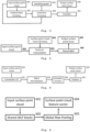
- FIG. 1 An embodiment of the method of estimation of hemodynamic parameters from a geometry of a blood vessel tree, using an artificial deep neural network, according to the invention, is discussed below in reference to Fig. 1 , showing a general flow chart.
- Patient-specific metadata and patient-specific volume image data are received.
- Patient-specific metadata is optional, but can improve accuracy.
- the patient-specific metadata that can include, but is not limited to features like age, sex, non-invasive blood pressure monitoring, medical history.
- Patient-specific volume image data is not optional and can be, but is not limited to: a computed tomography (CT) scan, computed tomography angiography (CTA) scan, coronary computed tomography angiography (CCTA) scan, magnetic resonance imaging (MRI) scan.
- CT computed tomography
- CTA computed tomography angiography
- CCTA coronary computed tomography angiography
- MRI magnetic resonance imaging
- Step 101 of retrieval of the data may involve actual measurements or just downloading the data from external source. It can be retrieved for example from an external drive, Picture archiving and communication system (PACS) or any other means.
- PACS Picture archiving and communication system
- This system can be a general purpose computer, dedicated, digital processing machine, distributed architecture, virtual machine or cloud resource. It needs to be selected to complete the task in the desired time.
- Azure cloud environment is used.
- an artery anatomy geometry is obtained in step 103.
- the step 103 of obtaining a geometry just involves loading a surface mesh.
- the step of obtaining 103 can involve geometry format transformation or even obtaining it via volume image segmentation.
- the step 103 of obtaining of the geometry can be done manually by a human expert, or automatically, by a computer algorithm, or semi-automatically with a computer algorithm and a human expert.
- the input artery anatomy geometry can be described as a surface mesh, point cloud surface, or any other relevant data structure. If the data structure is different than a point cloud surface, the artery anatomy geometry data structure must be transformed into a point cloud surface.
- the points in the point cloud have at least three parameters, which are coordinates in the three dimensional space, and additional number of features.
- Example features include, but are not limited to, distance to the centerline or geodesic distance from the vessel inlet (beginning).
- the surface mesh representation makes it easier to determine a centerline graph.
- a centerline graph is then extracted from the artery anatomy geometry.
- the centerline graph can be extracted manually by a human expert, automatically by a computer algorithm, or semi-automatically with a computer algorithm and a human expert.
- the centerline graph is described as a connected polygonal chain of 3D points in space.
- step 105 is realized in steps 204, 205, 206 and 207.
- the hemodynamic parameters are calculated for each point of the artery anatomy geometry point in the point cloud and can be cast on the centerline graph and estimated for each point in the centerline.
- the hemodynamic parameters can be, but are not limited to pressure drops, a fractional flow reserve (FFR), or any other related hemodynamic parameter.
- FFR is defined as a ratio between the pressure in the beginning of the artery and pressure in the measurement point.
- the result is then visualized, and a report is produced and send back or presented to the user in the step of outputting 106.
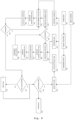
- a general artificial deep neural network (ADNN) model architecture used in the present embodiment of the invention is shown in Fig. 2 .
- the ADNN model shown in Fig. 2 is an example of ADNN model with architecture adapted for point cloud processing.
- the ADNN model comprises CSA blocks 204, Decoder blocks 205 and Shared MLP blocks 206.
- CSA blocks are fed with centerline graph 202 obtained in the step 104 and geometry of a blood vessel tree represented as a point cloud 203.
- both centerline graph 202 and surface point cloud 203 are obtained from geometry represented initially as a surface mesh 201.
- CSA blocks 204 form an encoder module.
- the input to the CSA blocks is the centerline graph 202 and the surface point cloud 203.
- CSA blocks return a vector which represents the whole surface point cloud 203.
- Decoder blocks 205 are fed with the vector returned by the CSA blocks 204 and with the surface point cloud 203 to return a decoded features point cloud.
- the decoded features point cloud is fed to the shared MLP blocks 206 for processing into selected hemodynamic parameter e.g. with 1D convolution layer. Finally, the result is postprocessed and outputted in a block 207.
- Figs. 3-6 Components of the general ADNN model architecture used in the present embodiment of the invention and shown in Fig. 2 , are shown in Figs. 3-6 .
- Corresponding centerline-set-abstraction (CSA) block is presented in Fig. 3
- its corresponding decoder block is presented in Fig. 4
- its corresponding shared multilayer perceptron (MLP) block is presented in Fig. 5 .
- PointNet block 305 shown in Fig. 3 is described in detail with reference to Fig. 6 .
- the specific configuration of the architecture used for the one other specific embodiment and experiments is shown in Fig. 7 .
- the ADNN model takes a centerline graph with V number of vertexes, and E number of edges 202 and surface point cloud with N in number of points and 203 with F in per point input features.
- the centerline graph 701 has an arbitral number of vertexes V , and a corresponding number of edges E .
- the number of points N in in the surface point cloud 702 is also arbitral and depends on the required resolution.
- the surface point cloud 702 has F in set to five. The first three describe the 3D spatial position, the fourth is the distance to the centerline, and fifth is a geodesic distance from the point to the inlet, where inlet is the beginning of the centerline.
- Both centerline graph and surface point cloud are extracted from the input vessel geometry represented as a surface mesh 201.
- the CSA block is shown in Fig. 3 .
- the input to the CSA block is an input surface point cloud 301 and centerline graph 303.
- the CSA block is parametrized with number of representatives to be sampled N out , grouping scales D 1 , D 2 , ..., D n , number of points to be grouped for each scale K 1 , K 2 , ..., K n and PointNet 305 configurations. Number n can be selected empirically.
- the input surface point cloud 301 is first downsampled to N out points with the Farthest Point Sampling (FPS) 302 algorithm.
- the FPS algorithm starts with the representative set R consisting of single point P_0 chosen arbitrarily from the point cloud.
- the point that is the farthest, in Euclidean distance sense, from the P_0 is extracted and added to the set R.
- the next point is chosen as the farthest, in Euclidean distance sense, from all the points in the R. This procedure is repeated iteratively until the set R is of required size.
- Resulting point cloud is to be referred as representative point cloud.
- the multi-scale grouping is performed independently for each point from the representative point cloud.
- the multi-scale grouping is defined as performing multiple independent groupings with different parametrizations.
- one grouping is a procedure of finding K i neighbors in the surface point cloud for the point from the representative point cloud, according to specified strategy.
- strategy is a process of determining an order in some manner of the surface point cloud points, according to the representative point, for which the grouping is performed.
- centerline grouping One of the possible grouping strategies is the centerline grouping discussed with reference to the present embodiment.
- the advantage of the centerline based grouping is that centerlines are very useful also in generation diagnostic images and therefore are often, already available in the patient specific geometry.
- Another advantage of centerlines is that it reflects information on topology of the vessel. In this strategy, all surface point cloud points and representative point cloud points get a closest, in the Euclidean distance sense, centerline vertex assigned. For each point in the representative point cloud, geodesic distances between assigned centerline vertex to the representative point and all centerline graph vertexes are computed.
- the scale parameter D i is used to extract only centerline vertexes, for which the geodesic distance is smaller than D i .
- Centerline vertexes extracted in this manner are used to query all surface point cloud points which got these vertexes assigned.
- Surface point cloud points extracted in this manner are considered a set of representative point's neighbors.
- the set of neighbors is further downsampled or upsampled to the specified number of neighbors K i . Grouping procedure is conducted in this manner for each scale specified in the CSA parametrization.
- PointNet 305 Extracted, multi-scale sets of neighbors are processed with PointNet 305 to obtain global neighborhood feature vectors.
- an independent PointNet block is used to extract a feature vector of size F i .
- the PointNet configurations are passed as a parametrization to the CSA block.
- the outputs of each scale PointNet are concatenated together point-wise.
- the output surface point cloud 306 is of size N out x ( F 1 + F 2 + ... F n ). Wherein F 1 , F 2 , ..., F n are feature vector sizes of each grouping scale.
- Applicable PointNet processing method is known from publication PointNet++: Deep Hierarchical Feature Learning on Point Sets in a Metric Space by Charles R. Qi, Li Yi, Hao Su, Leonidas J.
- the last CSA block groups all remaining points and creates one global embedding vector which represents the whole surface point cloud 203.
- This global embedding vector, together with embedding vectors from corresponding CSA blocks, and the surface point cloud 203 are used as an input to the Decoder blocks 205.
- the input to the PointNet block is an input surface point cloud 601 of spatial size N x F .
- the input surface point cloud is processed with multiple Shared MLP blocks 602 of specified parametrization.
- the number of Shared MLP blocks is a design choice.
- the last Shared MLP block outputs a surface point cloud of spatial size N x F out which is processed with Global Max Pooling 603 to yield single feature vector 604 representing surface point cloud of size F out .
- the number of used CSA blocks, their number of scales, corresponding distance parameters and spatial dimension of the output are a design choice. Stacking more blocks gives more generalizing capabilities, at the cost of more weights and risk of overfitting of the entire model. Stacking blocks allows extraction of local features, capturing fine geometric structures from small neighborhoods at first blocks. Such local features are further grouped into larger units in the next blocks and processed to produce higher level features. It is common to gradually extend the number of output feature channels from previous blocks, usually using the next powers of two, or by multiplying the number of channels by two. The number of blocks with their corresponding number of scale and distance parameters should be selected such that the model takes the entire point cloud into consideration at the last CSA block.
- the parameters D1, D2 of block 703 are set to 0.001 m, 0.002 m, respectively.
- the spatial dimension of the output point cloud for block 703 is set to 2048 x (16 + 16).
- the next CSA block 704 takes as an input the output of the previous block 703 and the centerline graph 701.
- the parameters D1, D2 of block 704 are set to 0.002 m, 0.004 m, respectively.
- the spatial dimension of the output point cloud for block 704 is set to 1024 x (32 + 32).
- the next CSA block 705 takes as an input the output of the previous block 704 and the centerline graph 701.
- the parameters D1, D2 of block 705 are set to 0.004 m, 0.008 m, respectively.
- the spatial dimension of the output point cloud for block 705 is set to 512 x (64, 64).
- the next CSA block 706 takes as an input the output of the previous block 705 and the centerline graph 701.
- the parameters D1, D2 of block 706 are set to 0.008 m, 0.012 m, respectively.
- the spatial dimension of the output point cloud for block 706 is set to 256 x (128 + 128).
- the next CSA block 707 takes as an input the output of the previous block 706 and the centerline graph 701.
- the parameters D1, D2 of block 707 are set to 0.012 m, 0.016 m, respectively.
- the spatial dimension of the output point cloud for block 707 is set to 128 x (128 + 128).
- the next CSA block 708 takes as an input the output of the previous block 707 and the centerline graph 701.
- the parameters D1, D2 of block 708 are set to 0.016 m, 0.032 m, respectively.
- the spatial dimension of the output point cloud for block 708 is set to 64 x (128 + 128).
- the last CSA block 709 takes as an input the output of the previous block 708 and the centerline graph 701.
- the parameter D1 708 is set to NONE, which is defined as grouping all remaining points.
- For last CSA block n 1.
- the spatial dimension of the output point cloud for block 709 is set to 256.
- the decoder module is built out of decoder blocks 205.
- the inputs to the decoder blocks are outputs of the CSA blocks 204 and for the last decoder block the surface point cloud 203 as well.
- the decoder block is shown in Fig. 4 .
- the input to the decoder block is an input surface point cloud from the previous decoder block 401 and surface point cloud from the respective CSA block 402.
- the decoder block is parametrized with Shared MLP configuration.
- the input surface point cloud from the previous decoder block 401 and surface point cloud from the respective CSA block 402 are an input to the features interpolation block 403.
- per-point features from the input surface point cloud from the previous decoder block are interpolated based on three nearest neighbors, in Euclidean distance sense, onto the surface point cloud from the respective CSA block 402.
- the surface point cloud from the respective CSA block with interpolated features is further processed.
- the interpolated surface point cloud is processed with Shared MLP 404 to obtain decoded features point cloud 405.
- the MLP block is one of typical mechanisms used for extraction features from bigger set of features - especially for data that is not linearly separable.
- the Shared MLP configuration is passed as a parametrization to the decoder block.
- the output surface point cloud i.e., decoded features point cloud 405 is of size N out x F out .
- a number of decoder blocks is a design choice and depends on the number of CSA blocks. Spatial dimension of output is also a design choice. Each decoder block requires input from the corresponding CSA block. Therefore, in the present embodiment the number of decoder blocks is seven.
- the first decoder block 716 gets an input from a previous decoder block 715, and from the surface point cloud 702. Its spatial output dimension is set to 64 x 256.
- Decoder block 715 gets an input from a previous decoder block 714, and from the CSA block 703. Its spatial output dimension is set to 128 x 128.
- Decoder block 714 gets an input from a previous decoder block 713, and from the CSA block 704. Its spatial output dimension is set to 256 x 128.
- Decoder block 713 gets an input from a previous decoder block 712, and from the CSA block 705. Its spatial output dimension is set to 512 x 128.
- Decoder block 712 gets an input from a previous decoder block 711, and from the CSA block 702. Its spatial output dimension is set to 1024 x 64.
- Decoder block 711 gets an input from a previous decoder block 710, and from the CSA block 707. Its spatial output dimension is set to 2048 x 32.
- the last decoder block 715 gets an input from CSA block 708 and CSA block 709. Its spatial output dimension is set to N in x 128.
- the point features are passed through the shared MLP blocks 206.
- the Shared MLP block is shown in Fig. 5 .
- the input to the Shared MLP block is an input surface point cloud 501 of spatial size N x F .
- the input surface point cloud is processed with 1D convolution 502 of specified number of output channels C .
- the output of the 1D convolution is then processed accordingly with 1D batch normalization layer 503, activation function 504 and Dropout layer 505.
- the output surface point cloud 506 is of spatial size N x C .
- the estimated hemodynamic parameter is determined by the parameter used in the training data set for training the network. If the ADNN is trained with FFR data - as in the present embodiment - then it estimates FFR data. On the other hand, the ADNN, according to embodiment of the invention, can be trained as well with other hemodynamic parameters, including pressure drops, wall shear stress and others.
- the number of shared MLP blocks is a design choice.
- only one shared MLP block 717 is used as shown in the Fig 7 .
- the number of convolutional channels is set to 128.
- the last step is to obtain the estimated per-point hemodynamic features output 207. It includes applying a series of post-processing procedures. In one embodiment, a single 1D convolutional layer 718 is used to cast the output to a required number of points N in and outputs it in step 719. Post processing may include, as in one embodiment casting output estimated hemodynamic parameters from points on the point cloud to points on a centerline graph or using these estimated hemodynamic parameters for further calculations in a CFD algorithm.
- the method comprises a step of obtaining of a set of training geometries in a form of surface mesh geometries or surface point cloud geometries.
- Hemodynamic parameters used in this embodiment are pressure drops or FFR.
- a pressure drop or FFR corresponding to individual points in every training geometry is determined in CFD simulation to form a set of training ground-truth values.
- Training data are formed by representing training geometries as surface point clouds and assigning pressure drops or FFR values to particular points in training geometries and then are used in training an ADNN model.
- Training data sets may comprise real data, artificial data, hybrid data or combination thereof and include patient-specific images, artery geometries and all related metadata.
- the training procedure is adapted to the method of estimation. Generally, it comprises a step of obtaining of a set of geometries of vessel trees - either corresponding to real patients or to artificial models or both. Further, it includes obtaining values of parameter to be estimated by the trained network. The values may be obtained in real measurement or with CFD simulations or both. Subsequently, the training data for the ADNN are prepared using the geometries and the corresponding parameters including representing the geometries as a point cloud. This is crucial for the invention as point cloud representation with geodesic distance grouping allows avoiding the need of setting arbitrarily selected parameters. Then the ADNN is trained.
- the ADNN is an artificial deep neural network having an architecture adapted for point cloud processing with distance based point grouping.
- the distance is defined as geodesic distance along the blood vessel tree. Geodesic distance, preferably, is distance along the centerline, thus a step of obtaining a blood vessel tree centerline graph is required. Specific example of training procedure is described below in detail with reference to Fig. 8 . It is noted though, that numerous alternative specific ways of training are available for the person skilled in the art, which are applicable as long as they meet requirements set out in claim 1.
- the training procedure is preceded by model initialization 801 and preparing the input data 804.
- the model initialization 801 includes initializing weights of the ADNN model which are sampled from a distribution of choice.
- the samples - input surface meshes or point clouds and hemodynamic features to be regressed are loaded into the memory.
- the samples are then preprocessed 805 - meshes are decomposed into centerline graphs and surface point clouds if needed. Then, additional features are computed and incorporated to each point on the point cloud as needed.
- the dataloaders are created 806 for both the train set 807 - on which the training is done, and for the validation set 815 - on which the model is evaluated during training procedure.
- the model training comprises of a set of operations which are repeated iteratively - one such set is called an epoch.
- Each epoch 802 starts from the training procedure 803 which utilizes the train dataloder 807.
- the dataloader yields batches of samples which are loaded into the memory 808 and processed with forward network procedure 809.
- the loss function between the desired and yielded result is calculated 810.
- the loss function is the Mean Squared Error (MSE), and the loss is calculated for each point of the input surface point cloud and result is averaged.
- MSE Mean Squared Error
- its gradient is used to perform backpropagation procedure 811, which estimates how much the network weights need to be tweaked, to obtain a lower loss in the current epoch.
- backpropagation procedure 811 which estimates how much the network weights need to be tweaked, to obtain a lower loss in the current epoch.
- model parameters are updated 812.
- the set of instructions applied to the data batch is called a training step.
- the training steps are repeated until there are no data batches left in the train data loader 813.
- the validation procedure commences 814. During the validation procedure, the model's weights are not changed. The validation process is performed to evaluate and monitor model's performance on a data that has not been included in the training set.
- the validation step comprises of similar instructions as the training step - loading next data batch 816, running forward procedure 817 and calculating loss function 818.
- the validation step differs from the training step in the absence of backpropagation procedure and model's parameters update.
- the validation steps are done iteratively until all the validation batches have been yielded 819.
- the requirements of the training process are checked 820. Requirements may comprise of checking whether validation loss decreased compared to the previously lowest value. If it does, the ADNN model is saved 821. Next, a stopping criterion 822 is checked. In one embodiment the stopping is defined as the number of epochs to be reached. If the stopping criterion is not met, the next epoch commences 802, otherwise the training ends 823.
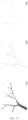
- a dataset of 1,700 synthetically generated vessel geometries, in form of a surface mesh was used.
- the training, validation and test set comprised of 1,500, 100 and 100 samples, respectively.
- Fig. 9 an example of a synthetic vessel is presented.
- a sample comprises of a centerline graph 901 (density of nodes showcased in 902) and a mesh representing vessel geometry 903.
- the computers in the sense of the above description, are to be understood as hardware devices including computers, microcontrollers, signal processing, programmable gate arrays, understood as hardware computers, graphic cards, application-specific integrated circuits, or other processing digital devices used for image processing, as well as distributed solutions including cloud computing environments.
- any reference signs placed between parentheses shall not be construed as limiting the claim.
- the use of the verb "comprise” does not mean that there are no elements or steps other than those stated in a claim.
- the article “a” or “an” preceding an element does not exclude the presence of a plurality of such elements.
Landscapes
- Health & Medical Sciences (AREA)
- Engineering & Computer Science (AREA)
- Medical Informatics (AREA)
- Public Health (AREA)
- Life Sciences & Earth Sciences (AREA)
- Biomedical Technology (AREA)
- General Health & Medical Sciences (AREA)
- Pathology (AREA)
- Primary Health Care (AREA)
- Epidemiology (AREA)
- Biophysics (AREA)
- Heart & Thoracic Surgery (AREA)
- Cardiology (AREA)
- Veterinary Medicine (AREA)
- Physics & Mathematics (AREA)
- Databases & Information Systems (AREA)
- Data Mining & Analysis (AREA)
- Animal Behavior & Ethology (AREA)
- Nuclear Medicine, Radiotherapy & Molecular Imaging (AREA)
- Surgery (AREA)
- Radiology & Medical Imaging (AREA)
- Molecular Biology (AREA)
- Vascular Medicine (AREA)
- Optics & Photonics (AREA)
- High Energy & Nuclear Physics (AREA)
- Oral & Maxillofacial Surgery (AREA)
- Dentistry (AREA)
- Physiology (AREA)
- Measuring And Recording Apparatus For Diagnosis (AREA)
- Image Analysis (AREA)
- Measuring Pulse, Heart Rate, Blood Pressure Or Blood Flow (AREA)
- Instructional Devices (AREA)
- Image Processing (AREA)
Priority Applications (7)
| Application Number | Priority Date | Filing Date | Title |
|---|---|---|---|
| EP23461531.8A EP4428871B1 (de) | 2023-03-09 | 2023-03-09 | Verfahren zum trainieren eines künstlichen neuronalen netzwerks zur schätzung eines hämodynamischen parameters, verfahren zur schätzung eines hämodynamischen parameters, computerprogrammprodukte und computersysteme |
| FIEP23793043.3T FI4523225T3 (fi) | 2023-03-09 | 2023-09-29 | Menetelmä keinotekoisen syväneuroverkon kouluttamiseksi hemodynaamisen parametrin arvioimiseksi, menetelmä hemodynaamisen parametrin arvioimiseksi, tietokoneohjelmatuotteet ja tietokonejärjestelmät |
| AU2023435419A AU2023435419A1 (en) | 2023-03-09 | 2023-09-29 | A method of training an artificial deep neural network for estimation of hemodynamic parameter, a method of estimation of hemodynamic parameter, computer program products and computer systems |
| PCT/IB2023/059810 WO2024184690A1 (en) | 2023-03-09 | 2023-09-29 | A method of training an artificial deep neural network for estimation of hemodynamic parameter, a method of estimation of hemodynamic parameter, computer program products and computer systems |
| DK23793043.3T DK4523225T3 (da) | 2023-03-09 | 2023-09-29 | Fremgangsmåde til træning af et kunstigt dybt neuralt netværk til estimering af hæmodynamisk parameter, en fremgangsmåde til estimering af hæmodynamisk parameter, computerprogramprodukter og computersystemer |
| EP23793043.3A EP4523225B1 (de) | 2023-03-09 | 2023-09-29 | Verfahren zum trainieren eines künstlichen neuronalen netzwerks zur schätzung eines hämodynamischen parameters, verfahren zur schätzung eines hämodynamischen parameters, computerprogrammprodukte und computersysteme |
| IL323114A IL323114A (en) | 2023-03-09 | 2025-09-02 | Method for training a deep artificial neural network for estimating hemodynamic parameters, method for estimating hemodynamic parameters, computer software products and computer systems |
Applications Claiming Priority (1)
| Application Number | Priority Date | Filing Date | Title |
|---|---|---|---|
| EP23461531.8A EP4428871B1 (de) | 2023-03-09 | 2023-03-09 | Verfahren zum trainieren eines künstlichen neuronalen netzwerks zur schätzung eines hämodynamischen parameters, verfahren zur schätzung eines hämodynamischen parameters, computerprogrammprodukte und computersysteme |
Publications (3)
| Publication Number | Publication Date |
|---|---|
| EP4428871A1 true EP4428871A1 (de) | 2024-09-11 |
| EP4428871B1 EP4428871B1 (de) | 2025-10-01 |
| EP4428871C0 EP4428871C0 (de) | 2025-10-01 |
Family
ID=85570113
Family Applications (2)
| Application Number | Title | Priority Date | Filing Date |
|---|---|---|---|
| EP23461531.8A Active EP4428871B1 (de) | 2023-03-09 | 2023-03-09 | Verfahren zum trainieren eines künstlichen neuronalen netzwerks zur schätzung eines hämodynamischen parameters, verfahren zur schätzung eines hämodynamischen parameters, computerprogrammprodukte und computersysteme |
| EP23793043.3A Active EP4523225B1 (de) | 2023-03-09 | 2023-09-29 | Verfahren zum trainieren eines künstlichen neuronalen netzwerks zur schätzung eines hämodynamischen parameters, verfahren zur schätzung eines hämodynamischen parameters, computerprogrammprodukte und computersysteme |
Family Applications After (1)
| Application Number | Title | Priority Date | Filing Date |
|---|---|---|---|
| EP23793043.3A Active EP4523225B1 (de) | 2023-03-09 | 2023-09-29 | Verfahren zum trainieren eines künstlichen neuronalen netzwerks zur schätzung eines hämodynamischen parameters, verfahren zur schätzung eines hämodynamischen parameters, computerprogrammprodukte und computersysteme |
Country Status (6)
| Country | Link |
|---|---|
| EP (2) | EP4428871B1 (de) |
| AU (1) | AU2023435419A1 (de) |
| DK (1) | DK4523225T3 (de) |
| FI (1) | FI4523225T3 (de) |
| IL (1) | IL323114A (de) |
| WO (1) | WO2024184690A1 (de) |
Citations (6)
| Publication number | Priority date | Publication date | Assignee | Title |
|---|---|---|---|---|
| US20140073976A1 (en) | 2012-09-12 | 2014-03-13 | Heartflow, Inc. | Systems and methods for estimating ischemia and blood flow characteristics from vessel geometry and physiology |
| WO2016075331A2 (en) * | 2014-11-14 | 2016-05-19 | Siemens Healthcare Gmbh | Method and system for purely geometric machine learning based fractional flow reserve |
| US20160166209A1 (en) | 2014-12-16 | 2016-06-16 | Siemens Healthcare Gmbh | Method and System for Personalized Non-Invasive Hemodynamic Assessment of Renal Artery Stenosis from Medical Images |
| EP3218872A2 (de) | 2014-11-14 | 2017-09-20 | Siemens Healthcare GmbH | Verfahren und system für fraktionsflussreserve auf der basis von rein geometrischem maschinellem lernen |
| EP3820357A1 (de) | 2019-01-11 | 2021-05-19 | Lifeflow Sp. Z O.O. | Patientenspezifische modellierung hämodynamischer parameter in koronararterien |
| CN114399608A (zh) | 2021-12-01 | 2022-04-26 | 杭州电子科技大学 | 一种用于血液动力学仿真的时变流场超分辨率重建方法 |
-
2023
- 2023-03-09 EP EP23461531.8A patent/EP4428871B1/de active Active
- 2023-09-29 DK DK23793043.3T patent/DK4523225T3/da active
- 2023-09-29 FI FIEP23793043.3T patent/FI4523225T3/fi active
- 2023-09-29 WO PCT/IB2023/059810 patent/WO2024184690A1/en active Pending
- 2023-09-29 EP EP23793043.3A patent/EP4523225B1/de active Active
- 2023-09-29 AU AU2023435419A patent/AU2023435419A1/en active Pending
-
2025
- 2025-09-02 IL IL323114A patent/IL323114A/en unknown
Patent Citations (6)
| Publication number | Priority date | Publication date | Assignee | Title |
|---|---|---|---|---|
| US20140073976A1 (en) | 2012-09-12 | 2014-03-13 | Heartflow, Inc. | Systems and methods for estimating ischemia and blood flow characteristics from vessel geometry and physiology |
| WO2016075331A2 (en) * | 2014-11-14 | 2016-05-19 | Siemens Healthcare Gmbh | Method and system for purely geometric machine learning based fractional flow reserve |
| EP3218872A2 (de) | 2014-11-14 | 2017-09-20 | Siemens Healthcare GmbH | Verfahren und system für fraktionsflussreserve auf der basis von rein geometrischem maschinellem lernen |
| US20160166209A1 (en) | 2014-12-16 | 2016-06-16 | Siemens Healthcare Gmbh | Method and System for Personalized Non-Invasive Hemodynamic Assessment of Renal Artery Stenosis from Medical Images |
| EP3820357A1 (de) | 2019-01-11 | 2021-05-19 | Lifeflow Sp. Z O.O. | Patientenspezifische modellierung hämodynamischer parameter in koronararterien |
| CN114399608A (zh) | 2021-12-01 | 2022-04-26 | 杭州电子科技大学 | 一种用于血液动力学仿真的时变流场超分辨率重建方法 |
Non-Patent Citations (6)
| Title |
|---|
| CHARLES R. QILI YIHAO SULEONIDAS J. GUIBAS, POINTNET++: DEEP HIERARCHICAL FEATURE LEARNING ON POINT SETS IN A METRIC SPACE, Retrieved from the Internet <URL:https://doi.org/10.48550/arXiv.1706.02413> |
| HE TONG ET AL: "GeoNet: Deep Geodesic Networks for Point Cloud Analysis", 2019 IEEE/CVF CONFERENCE ON COMPUTER VISION AND PATTERN RECOGNITION (CVPR), IEEE, 15 June 2019 (2019-06-15), pages 6881 - 6890, XP033687200, DOI: 10.1109/CVPR.2019.00705 * |
| HE, J. ET AL., LEARNING HYBRID REPRESENTATIONS FOR AUTOMATIC 3D VESSEL CENTERLINE EXTRACTION, 2020, Retrieved from the Internet <URL:arXiv.org> |
| JAVADOV AYDIN: "PointNet ++: Deep Hierarchical Feature Learning on Point Sets in a Metric Space [Paper Go-Through] | by Aydin Javadov | Medium", 30 August 2022 (2022-08-30), pages 1 - 15, XP093053275, Retrieved from the Internet <URL:https://medium.com/@ajavadov99/pointnet-deep-hierarchical-feature-learning-on-point-sets-in-a-metric-space-paper-go-through-b9121e559549> [retrieved on 20230610] * |
| LI: "Prediction of 3D Cardiovascular hemodynamics before and after coronary artery bypass surgery via deep learning", COMMUN BIOL, vol. 4, 22 January 2021 (2021-01-22), Li,, pages 1 - 12, XP093053274 * |
| PATRYK RYGIELMACIEJ ZIEBATOMASZ KONOPCZYNSKI: "Proceedings of the First International Workshop on Geometric Deep Learning in Medical Image Analysis", vol. 194, PMLR, article "Eigenvector Grouping for Point Cloud Vessel Labeling", pages: 202 |
Also Published As
| Publication number | Publication date |
|---|---|
| EP4523225A1 (de) | 2025-03-19 |
| WO2024184690A1 (en) | 2024-09-12 |
| AU2023435419A1 (en) | 2025-09-25 |
| DK4523225T3 (da) | 2025-12-01 |
| IL323114A (en) | 2025-11-01 |
| EP4428871B1 (de) | 2025-10-01 |
| FI4523225T3 (fi) | 2025-12-04 |
| EP4428871C0 (de) | 2025-10-01 |
| EP4523225B1 (de) | 2025-08-27 |
Similar Documents
| Publication | Publication Date | Title |
|---|---|---|
| US11847781B2 (en) | Systems and methods for medical acquisition processing and machine learning for anatomical assessment | |
| EP4091133B1 (de) | Verfahren und system zur automatischen erkennung von anatomischen strukturen in einem medizinischen bild | |
| CN115330669B (zh) | 预测解剖结构的疾病量化参数的计算机实现的方法、系统及存储介质 | |
| CN110517238B (zh) | Ct医学影像ai三维重建与人机交互可视化网络系统 | |
| CN112640000A (zh) | 根据医学数据对预测性数字孪生体模型的数据驱动的估计 | |
| US10726546B2 (en) | Tissue-to-flow image generation in medical imaging | |
| CN114387317B (zh) | Ct图像和mri三维图像的配准方法、装置 | |
| WO2021011775A1 (en) | Systems and methods for generating classifying and quantitative analysis reports of aneurysms from medical image data | |
| EP4390842A1 (de) | Tiefenlernenbasierte interaktive segmentierung für medizinische volumetrische bildgebungsdatensätze | |
| EP4390845B1 (de) | Computerimplementiertes verfahren, computerprogrammprodukt und bildgebungssystem | |
| CN112819831A (zh) | 基于卷积Lstm及多模型融合的分割模型生成方法及装置 | |
| JP7725580B2 (ja) | 形状プライアを用いた及び用いないセグメンテーション結果によって解剖学的異常を検出すること | |
| Grandhe et al. | Adaptive analysis & reconstruction of 3D DICOM images using enhancement based SBIR algorithm over MRI | |
| EP4428871B1 (de) | Verfahren zum trainieren eines künstlichen neuronalen netzwerks zur schätzung eines hämodynamischen parameters, verfahren zur schätzung eines hämodynamischen parameters, computerprogrammprodukte und computersysteme | |
| CN120510080A (zh) | 用于提供医学图像的图像获取信息的方法和系统 | |
| EP4123581A2 (de) | Verfahren zur automatischen segmentierung des sinus coronarius | |
| CN121127926A (zh) | 用于估计血液动力学参数的人工深度神经网络训练方法、血液动力学参数估计方法、计算机程序产品和计算机系统 | |
| EP4485352A1 (de) | Bildsegmentierung unter verwendung eines punktverteilungsmodells | |
| WO2025003031A1 (en) | Image segmentation using a point distribution model | |
| Roy et al. | MRI Image Reconstruction Through Contour Interpolation |
Legal Events
| Date | Code | Title | Description |
|---|---|---|---|
| PUAI | Public reference made under article 153(3) epc to a published international application that has entered the european phase |
Free format text: ORIGINAL CODE: 0009012 |
|
| STAA | Information on the status of an ep patent application or granted ep patent |
Free format text: STATUS: THE APPLICATION HAS BEEN PUBLISHED |
|
| AK | Designated contracting states |
Kind code of ref document: A1 Designated state(s): AL AT BE BG CH CY CZ DE DK EE ES FI FR GB GR HR HU IE IS IT LI LT LU LV MC ME MK MT NL NO PL PT RO RS SE SI SK SM TR |
|
| STAA | Information on the status of an ep patent application or granted ep patent |
Free format text: STATUS: REQUEST FOR EXAMINATION WAS MADE |
|
| 17P | Request for examination filed |
Effective date: 20241213 |
|
| STAA | Information on the status of an ep patent application or granted ep patent |
Free format text: STATUS: EXAMINATION IS IN PROGRESS |
|
| 17Q | First examination report despatched |
Effective date: 20250217 |
|
| GRAP | Despatch of communication of intention to grant a patent |
Free format text: ORIGINAL CODE: EPIDOSNIGR1 |
|
| STAA | Information on the status of an ep patent application or granted ep patent |
Free format text: STATUS: GRANT OF PATENT IS INTENDED |
|
| RIC1 | Information provided on ipc code assigned before grant |
Ipc: A61B 6/50 20240101ALI20250408BHEP Ipc: A61B 5/02 20060101ALI20250408BHEP Ipc: G16H 50/50 20180101ALI20250408BHEP Ipc: G16H 50/20 20180101ALI20250408BHEP Ipc: G16H 30/40 20180101AFI20250408BHEP |
|
| INTG | Intention to grant announced |
Effective date: 20250507 |
|
| GRAS | Grant fee paid |
Free format text: ORIGINAL CODE: EPIDOSNIGR3 |
|
| GRAA | (expected) grant |
Free format text: ORIGINAL CODE: 0009210 |
|
| STAA | Information on the status of an ep patent application or granted ep patent |
Free format text: STATUS: THE PATENT HAS BEEN GRANTED |
|
| AK | Designated contracting states |
Kind code of ref document: B1 Designated state(s): AL AT BE BG CH CY CZ DE DK EE ES FI FR GB GR HR HU IE IS IT LI LT LU LV MC ME MK MT NL NO PL PT RO RS SE SI SK SM TR |
|
| REG | Reference to a national code |
Ref country code: GB Ref legal event code: FG4D Ref country code: CH Ref legal event code: F10 Free format text: ST27 STATUS EVENT CODE: U-0-0-F10-F00 (AS PROVIDED BY THE NATIONAL OFFICE) Effective date: 20251001 |
|
| REG | Reference to a national code |
Ref country code: DE Ref legal event code: R096 Ref document number: 602023007162 Country of ref document: DE |