EP4123581A2 - Verfahren zur automatischen segmentierung des sinus coronarius - Google Patents
Verfahren zur automatischen segmentierung des sinus coronarius Download PDFInfo
- Publication number
- EP4123581A2 EP4123581A2 EP22179913.3A EP22179913A EP4123581A2 EP 4123581 A2 EP4123581 A2 EP 4123581A2 EP 22179913 A EP22179913 A EP 22179913A EP 4123581 A2 EP4123581 A2 EP 4123581A2
- Authority
- EP
- European Patent Office
- Prior art keywords
- image
- axial
- sagittal
- training
- coronal
- Prior art date
- Legal status (The legal status is an assumption and is not a legal conclusion. Google has not performed a legal analysis and makes no representation as to the accuracy of the status listed.)
- Pending
Links
Images


Classifications
-
- G—PHYSICS
- G06—COMPUTING OR CALCULATING; COUNTING
- G06T—IMAGE DATA PROCESSING OR GENERATION, IN GENERAL
- G06T7/00—Image analysis
- G06T7/0002—Inspection of images, e.g. flaw detection
- G06T7/0012—Biomedical image inspection
- G06T7/0014—Biomedical image inspection using an image reference approach
-
- A—HUMAN NECESSITIES
- A61—MEDICAL OR VETERINARY SCIENCE; HYGIENE
- A61B—DIAGNOSIS; SURGERY; IDENTIFICATION
- A61B6/00—Apparatus or devices for radiation diagnosis; Apparatus or devices for radiation diagnosis combined with radiation therapy equipment
- A61B6/50—Apparatus or devices for radiation diagnosis; Apparatus or devices for radiation diagnosis combined with radiation therapy equipment specially adapted for specific body parts; specially adapted for specific clinical applications
- A61B6/503—Apparatus or devices for radiation diagnosis; Apparatus or devices for radiation diagnosis combined with radiation therapy equipment specially adapted for specific body parts; specially adapted for specific clinical applications for diagnosis of the heart
-
- A—HUMAN NECESSITIES
- A61—MEDICAL OR VETERINARY SCIENCE; HYGIENE
- A61B—DIAGNOSIS; SURGERY; IDENTIFICATION
- A61B6/00—Apparatus or devices for radiation diagnosis; Apparatus or devices for radiation diagnosis combined with radiation therapy equipment
- A61B6/52—Devices using data or image processing specially adapted for radiation diagnosis
- A61B6/5211—Devices using data or image processing specially adapted for radiation diagnosis involving processing of medical diagnostic data
- A61B6/5223—Devices using data or image processing specially adapted for radiation diagnosis involving processing of medical diagnostic data generating planar views from image data, e.g. extracting a coronal view from a 3D image
-
- G—PHYSICS
- G06—COMPUTING OR CALCULATING; COUNTING
- G06T—IMAGE DATA PROCESSING OR GENERATION, IN GENERAL
- G06T7/00—Image analysis
- G06T7/10—Segmentation; Edge detection
- G06T7/11—Region-based segmentation
-
- G—PHYSICS
- G06—COMPUTING OR CALCULATING; COUNTING
- G06V—IMAGE OR VIDEO RECOGNITION OR UNDERSTANDING
- G06V10/00—Arrangements for image or video recognition or understanding
- G06V10/20—Image preprocessing
- G06V10/25—Determination of region of interest [ROI] or a volume of interest [VOI]
-
- G—PHYSICS
- G06—COMPUTING OR CALCULATING; COUNTING
- G06V—IMAGE OR VIDEO RECOGNITION OR UNDERSTANDING
- G06V10/00—Arrangements for image or video recognition or understanding
- G06V10/20—Image preprocessing
- G06V10/32—Normalisation of the pattern dimensions
-
- G—PHYSICS
- G06—COMPUTING OR CALCULATING; COUNTING
- G06V—IMAGE OR VIDEO RECOGNITION OR UNDERSTANDING
- G06V10/00—Arrangements for image or video recognition or understanding
- G06V10/40—Extraction of image or video features
- G06V10/44—Local feature extraction by analysis of parts of the pattern, e.g. by detecting edges, contours, loops, corners, strokes or intersections; Connectivity analysis, e.g. of connected components
-
- G—PHYSICS
- G06—COMPUTING OR CALCULATING; COUNTING
- G06V—IMAGE OR VIDEO RECOGNITION OR UNDERSTANDING
- G06V10/00—Arrangements for image or video recognition or understanding
- G06V10/70—Arrangements for image or video recognition or understanding using pattern recognition or machine learning
- G06V10/77—Processing image or video features in feature spaces; using data integration or data reduction, e.g. principal component analysis [PCA] or independent component analysis [ICA] or self-organising maps [SOM]; Blind source separation
- G06V10/774—Generating sets of training patterns; Bootstrap methods, e.g. bagging or boosting
-
- G—PHYSICS
- G06—COMPUTING OR CALCULATING; COUNTING
- G06V—IMAGE OR VIDEO RECOGNITION OR UNDERSTANDING
- G06V10/00—Arrangements for image or video recognition or understanding
- G06V10/70—Arrangements for image or video recognition or understanding using pattern recognition or machine learning
- G06V10/82—Arrangements for image or video recognition or understanding using pattern recognition or machine learning using neural networks
-
- A—HUMAN NECESSITIES
- A61—MEDICAL OR VETERINARY SCIENCE; HYGIENE
- A61B—DIAGNOSIS; SURGERY; IDENTIFICATION
- A61B6/00—Apparatus or devices for radiation diagnosis; Apparatus or devices for radiation diagnosis combined with radiation therapy equipment
- A61B6/02—Arrangements for diagnosis sequentially in different planes; Stereoscopic radiation diagnosis
- A61B6/03—Computed tomography [CT]
- A61B6/032—Transmission computed tomography [CT]
-
- G—PHYSICS
- G06—COMPUTING OR CALCULATING; COUNTING
- G06T—IMAGE DATA PROCESSING OR GENERATION, IN GENERAL
- G06T2200/00—Indexing scheme for image data processing or generation, in general
- G06T2200/04—Indexing scheme for image data processing or generation, in general involving 3D image data
-
- G—PHYSICS
- G06—COMPUTING OR CALCULATING; COUNTING
- G06T—IMAGE DATA PROCESSING OR GENERATION, IN GENERAL
- G06T2200/00—Indexing scheme for image data processing or generation, in general
- G06T2200/08—Indexing scheme for image data processing or generation, in general involving all processing steps from image acquisition to 3D model generation
-
- G—PHYSICS
- G06—COMPUTING OR CALCULATING; COUNTING
- G06T—IMAGE DATA PROCESSING OR GENERATION, IN GENERAL
- G06T2207/00—Indexing scheme for image analysis or image enhancement
- G06T2207/10—Image acquisition modality
- G06T2207/10072—Tomographic images
- G06T2207/10081—Computed x-ray tomography [CT]
-
- G—PHYSICS
- G06—COMPUTING OR CALCULATING; COUNTING
- G06T—IMAGE DATA PROCESSING OR GENERATION, IN GENERAL
- G06T2207/00—Indexing scheme for image analysis or image enhancement
- G06T2207/20—Special algorithmic details
- G06T2207/20076—Probabilistic image processing
-
- G—PHYSICS
- G06—COMPUTING OR CALCULATING; COUNTING
- G06T—IMAGE DATA PROCESSING OR GENERATION, IN GENERAL
- G06T2207/00—Indexing scheme for image analysis or image enhancement
- G06T2207/20—Special algorithmic details
- G06T2207/20081—Training; Learning
-
- G—PHYSICS
- G06—COMPUTING OR CALCULATING; COUNTING
- G06T—IMAGE DATA PROCESSING OR GENERATION, IN GENERAL
- G06T2207/00—Indexing scheme for image analysis or image enhancement
- G06T2207/20—Special algorithmic details
- G06T2207/20084—Artificial neural networks [ANN]
-
- G—PHYSICS
- G06—COMPUTING OR CALCULATING; COUNTING
- G06T—IMAGE DATA PROCESSING OR GENERATION, IN GENERAL
- G06T2207/00—Indexing scheme for image analysis or image enhancement
- G06T2207/30—Subject of image; Context of image processing
- G06T2207/30004—Biomedical image processing
- G06T2207/30048—Heart; Cardiac
-
- G—PHYSICS
- G06—COMPUTING OR CALCULATING; COUNTING
- G06T—IMAGE DATA PROCESSING OR GENERATION, IN GENERAL
- G06T2207/00—Indexing scheme for image analysis or image enhancement
- G06T2207/30—Subject of image; Context of image processing
- G06T2207/30004—Biomedical image processing
- G06T2207/30101—Blood vessel; Artery; Vein; Vascular
-
- G—PHYSICS
- G06—COMPUTING OR CALCULATING; COUNTING
- G06V—IMAGE OR VIDEO RECOGNITION OR UNDERSTANDING
- G06V2201/00—Indexing scheme relating to image or video recognition or understanding
- G06V2201/03—Recognition of patterns in medical or anatomical images
- G06V2201/031—Recognition of patterns in medical or anatomical images of internal organs
Definitions
- the present invention relates to a method for automatic segmentation of coronary sinus, in particular by neural networks. Moreover, the present invention relates to a computer for executing said method, and to a related computer program product.
- the method generates a 3D mask of a coronary sinus of the patient based on a 3D image acquired through a CT apparatus.
- Image segmentation has an essential role in computer-aided diagnosis systems in different applications.
- medical imaging modalities such as microscopy, dermoscopy, X-ray, ultrasound, computed tomography (CT), magnetic resonance imaging (MRI), and positron emission tomography attract researchers to implement new medical image-processing algorithms.
- Image segmentation is considered the most essential medical imaging process as it extracts the region of interest (ROI) through a semi-automatic or automatic process. It divides an image into areas based on a specified description, such as segmenting body organs/tissues in the medical applications for border detection, tumor detection/segmentation, and mass detection.
- ROI region of interest
- a method for automatic segmentation of coronary sinus by neural networks a computer for executing said method, and a related computer program product are provided, as defined in the annexed claims.
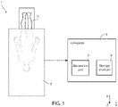
- Figure 1 shows, in a triaxial Cartesian reference system defined by axis X, Y and Z, a medical equipment 1 comprising a medical apparatus 3 and a computer 5, operatively coupled between them.
- the medical apparatus 3 is a Computed Tomography (CT) apparatus (or machine), referred to in the following as CT apparatus 3.
- CT apparatus 3 Computed Tomography
- the medical apparatus 3 and the computer 5 are electrically coupled between them through wired connections (not shown), or they are wirelessly coupled between them (ex., through transmitting/receiving units, not shown).
- the computer 5 is, for example, a general-purpose computer, a cloud, a super computer, a personal computer, a laptop computer, a palmtop computer, a mobile device, a tablet computer, a notebook computer, a desktop computer, a workstation computer, a server, or the like.
- the computer 5 comprises an elaboration unit 7 (e.g., a processor, a microprocessor or a central processing unit) and a computer-readable storage medium 9 (a memory, such as a flexible disk, hard disk, magnetic tape, any other magnetic medium, a CD-ROM, DVD, any other optical medium, punch cards, paper tape, a RAM, a PROM, an EPROM, a FLASH-EEPROM), coupled between them.
- an elaboration unit 7 e.g., a processor, a microprocessor or a central processing unit
- a computer-readable storage medium 9 a memory, such as a flexible disk, hard disk, magnetic tape, any other magnetic medium, a CD-ROM, DVD,
- the CT apparatus 3 acquires, in a per se known way, a 3D image 15 of a body region of a patient 11.
- the body region is a region of interest of the body of the patient 11 and comprises an anatomical structure of interest of the patient 11 (in particular a coronary sinus shown in Figure 7 with the reference number 100, i.e., the group of veins joined together to form a large vessel that collects blood from the heart muscle and that delivers less-oxygenated blood to the right atrium of the patient 11).
- the body region comprises the coronary sinus and one or more further body tissues or organs that are adjacent, or in proximity, to the coronary sinus. Therefore, the 3D image 15 always represents the coronary sinus of the patient 11; this is achieved by appropriately programming the CT apparatus 3, in a per se known way, so that it generates and detect rays oriented in such a way to pass through said body region.
- the 3D image 15, representing the body region of the patient 11, is provided as an output of the CT apparatus 3.
- the 3D image 15 is in a Digital Imaging and Communications in Medicine (DICOM) format. This format allows to store medical images as well as the patient information. Personal data is anonymized; thus, no patient data is required for the proposed method.
- the DICOM file could present the information about the coordinates of the image, for example, Image Orientation, Image Position, Slice Thickness. This is useful when the conversion from DICOM to a 3D image array is performed.
- DICOM Digital Imaging and Communications in Medicine
- Input data generated by the CT apparatus 3 and including the 3D image 15, are received by the computer 5.
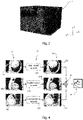
- the input data are stored in the storage medium 9 and are processed by the elaboration unit 7 to obtain a 3D mask (shown in Figure 4 with the reference number 30) of the coronary sinus of the patient 11.
- the computer 5 implements an identification (or segmentation) method 20 to generate the 3D mask 30 based on the input data (thus on the 3D image 15).
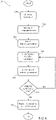
- Figure 3 shows the identification method 20 according to an embodiment of the present invention.
- a step S01 of the identification method 20 the input data are acquired through the CT apparatus 3 and are received by the computer 5, as previously described.
- the 3D image 15 comprised in the input data is pre-processed to generate a series of 2D images (shown in Figure 4 with the reference number 13).
- the 3D image 15 comprises information of the body region along three scanning planes, also known as anatomical planes (here considered orthogonal with the axis X, Y and Z, although it is clear that each scanning plane could be a weighted combination of planes defined by the axis X, Y and Z).
- step S03 the 3D image 15 is decomposed into the series of 2D images 13 so that the series of 2D images 13 comprises axial images (shown in Figure 4 with the reference number 13a, each axial image 13a being associated to a respective axial plane that is parallel to an XY plane defined by the axis X and Y), sagittal images (shown in Figure 4 with the reference number 13b, each sagittal image 13b being associated to a respective sagittal plane that is parallel to an XZ plane defined by the axis X and Z) and coronal images (shown in Figure 4 with the reference number 13c, each coronal image 13c being associated to a respective coronal plane that is parallel to an YZ plane defined by the axis Y and Z).
- axial images shown in Figure 4 with the reference number 13a, each axial image 13a being associated to a respective axial plane that is parallel to an XY plane defined by the axis X and Y
- sagittal images shown in Figure 4 with
- each axial image 13a is a respective first 2D matrix having second sizes (e.g., N rows and L levels)
- each sagittal image 13b is a respective second 2D matrix having third sizes (e.g., M columns and L levels)
- each coronal image 13c is a respective third 2D matrix having fourth sizes (e.g., N rows and M columns).
- step S03 the series of 2D images 13 is further pre-processed through normalization.
- x values are referred to Hounsfield units (HU) corresponding to the x-ray attenuation (which is different for tissues with different density).
- a step S05 of the identification method 20 immediately consecutive to the step S03, the series of 2D images 13 is iteratively processed through a first neural network model (shown in Figure 4 with the reference number 22).
- the first neural network model 22 comprises a plurality of neural networks, and in particular an axial neural network (shown in Figure 4 with the reference number 22a) for processing the axial images 13a, a sagittal neural network (shown in Figure 4 with the reference number 22b) for processing the sagittal images 13b, and a coronal neural network (shown in Figure 4 with the reference number 22c) for processing the coronal images 13c.
- Each neural network 22a, 22b, 22c is trained, as better described in the following, to generate, based on each 2D image 13 received as input, a respective 2D probability map (shown in Figure 4 with the reference number 24).
- the axial neural network 22a generates a respective axial 2D probability map 24a based on each axial image 13a
- the sagittal neural network 22b generates a respective sagittal 2D probability map 24b based on each sagittal image 13b
- the coronal neural network 22c generates a respective coronal 2D probability map 24c based on each coronal image 13c.
- Each 2D probability map 24a, 24b, 24c is a 2D matrix having same sizes as the respective axial, sagittal or coronal image 13a, 13b, 13c: each 2D axial probability map 24a is a fourth 2D matrix having the second sizes, each 2D sagittal probability map 24b is a fifth 2D matrix having the third sizes, and each 2D coronal probability map 24c is a sixth 2D matrix having the fourth sizes.
- Each cell of such 2D matrix is thus associated with a respective pixel of the 2D image 13 received as input and has a respective value (comprised between, or equal to, 0 and 1) indicative of a probability that the correspondent pixel of the 2D image 13 belongs to the coronary sinus of the patient 11 (i.e., that the correspondent pixel of the 2D image 13 represents a portion of the coronary sinus).
- each neural network 22a, 22b, 22c includes two parts: a first part, an encoder, used to reduce the resolution of the input 2D image 13 in order to extract contextual information (i.e., features of the 2D images 13a, 13b, 13c); and a second part consequent to the encoder, a decoder, used to increase the resolution of the extracted contextual information in order to determine an exact location of the feature of interest (i.e., the coronary sinus of the patient 11).
- each neural network 22a, 22b, 22c has an architecture based on Unet or Linknet.
- each neural network 22a, 22b, 22c may comprise at least one convolutional layer, max-pooling layer, upsampling layer, skip-connection layer, batch-normalization layer, rectified linear layer, concatenation layer, and any other layers in any appropriate configuration.
- each neural network 22a, 22b, 22c presents the previously described encoder-decoder structure, but the encoder is replaced with a convolutional neural network (CNN), for example trained on large datasets (such as ImageNet) to further improve the extraction of the contextual information.
- CNN convolutional neural network
- Examples of convolutional neural networks used as encoder are VGG, ResNet and Inception.
- the task of segmentation of some structure (or several different structures) in an image is also called semantic segmentation.
- these examples of CNN are state-of-the-art techniques.
- Region-based Convolutional Neural Networks can be used for the semantic segmentation task.
- CNNs Convolutional Neural Networks
- FCNs Fully Convolutional Networks
- Simpler versions of CNN or FCN can also be used for semantic segmentation task.
- the CNN may comprise convolutional, pooling, activation layers, and a fully connected layer at the end; other layers, such as a normalization layer, can also be part of CNN.
- FCN is similar to CNN, with the only difference that compared to CNN, FCN can accept an image of any size as input, since FCN uses 1x1 convolutional layers instead of fully connected layers.
- each neural network 22a, 22b, 22c generates, based on the respective input 2D image 13a, 13b, 13c, one respective 2D probability map 24a, 24b, 24c at each iteration (i.e., at each time instant or time interval). Therefore, the step S05 is repeated multiple times and iterated until all the 2D images 13 have been processed and all the respective 2D probability maps 24a, 24b, 24c have been generated.
- the 2D probability maps 24a, 24b, 24c obtained based on all the 2D images 13 are processed to generate the 3D mask 30.
- the 3D mask 30 is generated by merging together all the generated 2D probability maps 24a, 24b, 24c, thus obtaining a 3D probability map (schematically shown in Figure 4 with the reference number 28), and by saturating the 3D probability map 28 thus generating the 3D mask 30.
- the 3D probability map 28 is a second 3D matrix having the first sizes (i.e., as the 3D image 15), where each cell of the 3D matrix is associated with a respective 3D pixel of the acquired 3D image 15 and has a respective value (comprised between, or equal to, 0 and 1) indicative of a probability that the correspondent 3D pixel of the 3D image 15 belongs to the coronary sinus of the patient 11 (i.e., indicative of a probability that the correspondent 3D pixel of the 3D image 15 represents a portion of the coronary sinus).
- the generated 2D probability maps 24a, 24b, 24c are merged together as a weighted average ensemble so as to allow the predictions on the different types of anatomical planes to contribute in a proportional way.
- Y is the 3D probability map 28
- Y i is the axial image 13a and i is comprised between 0 and a total number of axial images 13a
- Y j is the sagittal image 13b and j is comprised between 0 and a total number of sagittal images 13b
- Y k is the coronal image 13c and k is comprised between 0 and a total number of coronal images 13c
- w 1 is an axial weight for the axial images 13a
- w 2 is a sagittal weight
- a specific weight can be assigned to each 2D image 13.
- the weights w 1 , w 2 , w 3 for each neural network 22a, 22b, 22c can be set to a same value (so that each neural network 22a, 22b, 22c makes the same contribution to the 3D probability map 28), or they can be calculated by using per se known techniques, such as a random search or a grid search.
- a per se known optimization procedure such as a linear solver or a gradient descent optimizer, e.g., XGBoost algorithm
- a per se known optimization procedure can be used to estimate the weights w 1 , w 2 , w 3 , using a unit norm weight constraint to ensure that the sum of the weights w 1 , w 2 , w 3 is unitary.
- the 3D probability map 28 is then saturated to obtain the 3D mask 30.
- the 3D mask 30 is a segmentation map in the form of a third 3D matrix having the first sizes (i.e., as the 3D image 15 and the 3D probability map 28), where each cell of the 3D mask 30 is associated with a respective 3D pixel (also known as voxel) of the acquired 3D image 15 and has a respective binary value (0 or 1) indicative of the belonging of the considered 3D pixel of the 3D image 15 to the coronary sinus of the patient 11 (i.e., indicative of the fact that such pixel of the 3D image 15 represents or not a portion of the coronary sinus).
- each cell value of the 3D probability map 28 is compared to a threshold value: if the considered 3D probability map cell value is greater than, or equal to, the threshold value, the correspondent cell value of the 3D mask 30 is set to 1; otherwise, if the considered 3D probability map cell value is lower than the threshold value, the correspondent cell value of the 3D mask 30 is set to 0.
- the threshold value is determined during designing and training of the first neural network model 22. In an exemplary and non-limiting case, the threshold value is comprised between 0.5 and 1.
- the obtained 3D mask 30 is a mask that, when applied (i.e., as a Hadamard product) to the 3D image 15 used to calculate it, identifies and selects the coronary sinus while discarding any other body tissues or organs present in the 3D image 15. Consequently, by applying the 3D mask 30 to the 3D image 15, a 3D model (or representation) of the coronary sinus is obtained, extrapolated from its original environment (e.g., the adjacent tissues or organs).
- the 3D model is a fifth 3D matrix having the first sizes and comprising a plurality of 3D pixels, each 3D pixel of the 3D model being associated to a respective 3D pixel of the 3D image 15 and having a respective value that is equal to a value of the respective 3D pixel of the 3D image 15 if the associated 3D pixel of the 3D image 15 represents the coronary sinus, or that is set to a predefined value (e.g., to 0) if the respective 3D pixel of the 3D image 15 does not represents the coronary sinus.
- the 3D model is also shown in Figure 7 with the reference number 50.
- the training method 40 can be executed before the step S01 of the identification method 20 to train the neural networks 22a, 22b, 22c, and thus is a further part of the identification method 20.
- the training method 40 is exemplarily described with reference to the axial neural network 22a, although it is clear that it can be analogously applied to the sagittal and coronal neural networks 22b, 22c by changing the data received as input.
- the computer 5 receives as input a training dataset comprising a plurality of training input data (and thus a respective plurality of 3D training images 15) generated by the CT apparatus 3, and a respective plurality of training labels.
- Each training label is associated to a respective 3D training image 15 (i.e., a respective fourth 3D matrix having the first sizes);
- each cell of the 3D label 30 is associated with a respective 3D pixel (also known as a voxel) of the acquired 3D image 15 and has a respective binary value (1 or 0) indicative of the belonging or not of the considered 3D pixel of the 3D image 15 to the coronary sinus of the patient 11.
- the training labels are provided by an operator (such as a physician skilled in segmenting the 3D training images 15 and in identifying the coronary sinus), who segments each 3D training image 15 through visual inspection.
- each 3D training image 15 of the training dataset is pre-processed to generate a respective series of 2D training images 13, as previously described with reference to step S03 of the identification method 20.
- the training label of the 3D training image 15 generating said series is associated with each 2D training image 13 of the series. Since the training method 40 is described with reference to the axial neural network 22a, only the axial training images 13a generated from the training dataset are considered in the following.
- a step S24 (optional) of the training method 40, immediately consecutive to the step S22, the axial training images 13a from the plurality of series of 2D training images 13 are processed through data augmentation to obtain augmented axial training images 13a (i.e., an higher number of axial training images 13a).
- Data augmentation is a technique used to increase the diversity of the training dataset at input of a neural network, by applying random transformations to such training dataset.
- random transformations may be applied to each axial training image 13a, such as zoom, rotation, vertical shift, horizontal shift, elastic transformations, contrast, brightness. Parameters of the random transformation are selected empirically so that, after the transformations, the realism of the augmented axial training images 13a is preserved.
- each one of the axial training images 13a (augmented or not) from the plurality of series of 2D training images 13 is set as input to the axial neural network 22a.
- the axial neural network 22a is thus trained, based on the axial training images 13a and by means of an optimization algorithm, in order to create an optimized set of weights of the axial neural network 22a.
- the optimization algorithm is an algorithm that determines how the weights of a neural network are calculated and updated at each stage of training. Examples of known optimization algorithms are Adam, Adagrad and Adadelta. Tuning parameters of the axial neural network 22a and/or of the optimization algorithm may be adjusted empirically or by means of a random or grid search.
- the optimized set of weights of the axial neural network 22a is therefore found by means of the optimization algorithm while the axial neural network 22a iteratively processes the axial training images 13a generated from the training dataset.
- the optimized set of weights of the axial neural network 22a is saved in a file (e.g., stored in the storage medium 9) for further initialization of the axial neural network 22a.
- other hyper-parameters useful for the training are, for example (since all parameters depend on the task and can be adjusted either empirically or through grid search):
- a validation of the axial neural network 22a with the optimized set of weights is performed.
- the axial neural network 22a is tested by providing to it as an input a testing dataset, analogous to the training dataset but based on data acquired from patients different from the ones of the training dataset.
- the testing dataset comprises a plurality of testing input data (and thus a respective plurality of testing 3D images 15) generated by the CT apparatus 3, and a respective plurality of testing labels.
- the axial neural network 22a generates a respective plurality of testing axial 2D probability maps 24a from the axial testing images 13a extracted from the 3D testing images 15 of the testing dataset.
- a known metric (such as S ⁇ rensen-Dice coefficient, Jaccard Similarity Coefficient, or Pixel Accuracy) is applied to the testing axial 2D probability maps 24a to assess, based on the testing labels, the accuracy of detection of the axial neural network 22a. For example, if the accuracy is greater than or equal to a threshold accuracy value (e.g., ranging between about 0.7 and about 1), the axial neural network 22a having the optimized set of weights is confirmed as correctly working (i.e., is suitable for the recognition task) and it can be used for the identification method 20; otherwise, if the accuracy (or the ROC area) is lower than the threshold accuracy value, the axial neural network 22a is not confirmed as correctly working and the training method 40 is carried out again.
- a threshold accuracy value e.g., ranging between about 0.7 and about 1
- the axial neural network 22a having the optimized set of weights is confirmed as correctly working (i.e., is suitable for the recognition task) and it can be used for the identification method 20
- a Unet model (comprises encoder and decoder parts) can be used.
- the encoder part of the Unet model can be replaced via a pre-trained model that was pre-trained on a large dataset, commonly available.
- the procedure is as follows: a CNN (e.g. resnet18, resnet50, resnet101, densenet, vgg16) is trained on the large dataset (e.g. Imagenet); then, the first part (encoder) of the Unet model is replaced with this pre-trained neural network (that replaces the first half with the architecture layers and weights acquired after this pre-training); and then the Unet is trained on the previously mentioned dataset specific for coronary sinus segmentation.
- the architecture of the pre-trained model is chosen either empirically or through grid search. For example, resnet50 (for sagittal and coronal neural networks) and resnet101 (for axial neural network) were chosen and trained on Imagenet dataset.
- the weights w 1 , w 2 , w 3 of the weighted average ensemble are also calculated, as previously described.
- Figure 6 shows the identification method 20 according to a different embodiment of the present invention.
- the identification method 20 of Figure 6 is analogous to the identification method 20 of Figure 3 but also comprises additional steps executed to further increase the segmentation accuracy of the coronary sinus. These additional steps are executed iteratively starting from the 3D model 50 in order to accurately reconstruct the structure of the coronary sinus in a step-by-step approach.
- step S50 of the identification method 20 of Figure 6 the 3D model 50 is generated as previously described with reference to Figure 3 .
- the 3D model 50 is processed to extract a starting 2D image 70 from the 3D model 50.
- the starting 2D image 70 is a 2D image of the 3D model 50 (i.e., a slice of the 3D model), for example orthogonal to one of the directions of the 3D model 50 (i.e., orthogonal to the X, Y or Z axis).
- the starting 2D image 70 is considered in the following as a slice parallel to the XY plane and orthogonal to the Z axis.
- the starting 2D image 70 is taken at about half of its length along the Z axis (ex., at L/2, where the 3D model 50 has N rows in the X axis, M columns in the Y axis and L levels in the Z axis): the choice of L/2 maximizes the probability of finding a portion of the coronary sinus in the starting 2D image 70.
- a number of portions of the coronary sinus (in particular, a number of branches of the coronary sinus) present in the starting 2D image 70 are detected and, for each branch, a respective area of interest within the starting 2D image 70 is identified.
- the starting 2D image 70 is processed to identify if (and if yes, how many and in which positions) branches of the coronary sinus are present in the starting 2D image 70.
- each branch is shown in section in the starting 2D image 70 by means of its contour that has a circular shape (i.e., a closed polygonal shape), as it can be seen in Figure 7 where the branch contours in the starting 2D image 70 are identified with the reference number 74.
- the branch contours 74 are identified by processing the starting 2D image 70 through a second neural network model (also called contour neural network model), better discussed in the following.
- the starting 2D image 70 is set as input to a first contour neural network of the second neural network model, which is trained to identify branch contours in the input 2D image (i.e., to identify the shapes of the branch contours 74 in the starting 2D image 70). Further details about the second neural network model are given in the following.
- a respective centre e.g., centre of mass
- extension of the branch contour are identified in step S54.
- a respective minimum enclosing circle is calculated (i.e., the smallest circle that completely encloses the branch contour 74), and both the centre and the radius of the minimum enclosing circle are identified. These centre and radius correspond respectively to the centre and the extension of the branch contour.
- the area of interest completely represents the branch contour, and no portions of the latter are excluded from it.
- step S54 both the branch contours (with the respective centres) and the respective areas of interest are determined.
- Figure 8 shows, in the XZ plane orthogonal to the starting 2D image 70, an exemplary area of interest 72, the respective branch contour 74 and the centre 76 of the branch contour 74.
- the description relates for simplicity to the case of only one area of interest 72 in the starting 2D image 70, although it is evident that it analogously applies to each area of interest 72 when a plurality of areas of interest 72 are identified in the starting 2D image 70.
- an i th propagation direction 78 is calculated for the area of interest 72 (also named i th area of interest 72).
- i th propagation direction 78 is described in the following for the following iterations (i>1).
- an (i+1) th area of interest 80 is determined.
- the (i+1) th area of interest 80 extends orthogonally to the i th propagation direction 78, is centred with the i th centre 76 along the i th propagation direction 78 and, for example, is spaced with respect to the i th area of interest 72 of a predefined distance (e.g., determined empirically and, for example, equal to 2 pixels) measured along the i th propagation direction 78 between the centres of the i th and (i+1) th areas of interest.
- a predefined distance e.g., determined empirically and, for example, equal to 2 pixels
- the (i+1) th area of interest 80 is selected in a further 2D image (slice) of the 3D model 50 that is perpendicular to the i th propagation direction 78 and that is indicated with the reference number 82 in Figure 8 .
- step S58 a number of branch contours are detected in the (i+1) th area of interest 80.
- the branch contours in the (i+1) th area of interest 80 are identified by processing the (i+1) th area of interest 80 through the second neural network model.
- the second neural network model comprises a plurality of contour neural networks (e.g., CNN, where one of them is the previously mentioned first contour neural network), each being designed to receive as input a respective 2D image having specific sizes (different from the sizes of the 2D images inputted to the other contour neural networks) and to identify branch contours in such 2D image.
- contour neural networks e.g., CNN, where one of them is the previously mentioned first contour neural network
- the area of search of the second neural network model should vary accordingly (e.g., from 2 to 512 pixels); it is very difficult to come up with a unique neural network architecture that provides equally accurate branch contour segmentation for such a huge variation in dimension of the branch contours, so several neural networks have been used here, each of which is responsible for an input of a particular width range.
- each neural network has a particular "neural network input size", i.e. it cannot take any other shapes as an input. If the size of the (i+1) th area of interest 80 does not correspond to the input size of one of the contour neural network, the (i+1) th area of interest 80 is resized to the closest input shape accepted by one of the contour neural network. This is via known interpolation methods (e.g., https://docs.opencv.org/3.4/da/d54/group_imgproc_transform.html#ga5bb5alfea74ea38ela5445ca803ff121, for example through bilinear interpolation).
- the second neural network model comprises four contour neural networks: the first contour neural network receives as input 2D images with first input sizes (e.g., 352 pixels, for (i+1) th areas of interest 80 with sizes ranging from, for example, 160 to 512 pixels); a second contour neural network receives as input 2D images with second input sizes (e.g., 128 pixels, for (i+1) th areas of interest 80 with sizes ranging from, for example, 96 to 159 pixels); a third contour neural network receives as input 2D images with third input sizes (e.g., 64 pixels, for (i+1) th areas of interest 80 with sizes ranging from, for example, 48 to 95 pixels); and a fourth contour neural network receives as input 2D images with fourth input sizes (e.g., 32 pixels, for (i+1) th areas of interest 80 with sizes ranging from, for example, 2 to 47 pixels).
- the architecture of each contour neural network is analogous to the neural networks previously described (e.g., 22a, 22b
- the (i+1) th area of interest 80 is resized (if necessary) and is taken as input by the corresponding contour neural network that, by processing it, outputs a respective 2D probability map where each pixel is indicative of the probability that this pixel belongs to the coronary sinus.
- the correspondent 2D probability map is resized to have same sizes of the initial (i+1) th area of interest 80.
- the 2D probability map is then processed so that a correspondent 2D mask of the branches of the coronary sinus in the (i+1) th area of interest 80 is generated. This is done analogously to what described before, i.e.
- the values of the 2D probability map are compared with a threshold value (comprised between 0 and 1 and, for example, between 0.5 and 1) and each pixel of the 2D probability map having a value that is greater than or equal to the threshold value is assigned to 1, otherwise to 0.
- a threshold value (comprised between 0 and 1 and, for example, between 0.5 and 1) and each pixel of the 2D probability map having a value that is greater than or equal to the threshold value is assigned to 1, otherwise to 0.
- the same vein branch of the coronary sinus that is present in the i th area of interest 72 will be also present in the (i+1) th area of interest 80. Nonetheless, the vein branch of the coronary sinus that is present in the i th area of interest 72 could be absent in the (i+1) th area of interest 80 if this vein branch ended between the i th and the (i+1) th area of interest 72, 80; another possibility is that the vein branch in the i th area of interest 72 splits in two (or more) vein branches between the i th and the (i+1) th area of interest 72, 80 so that a plurality of branch contours are detected in the (i+1) th area of interest 80.
- a respective centre and extension of the branch contour 84 are identified in step S58 analogously to what previously described.
- the centre (in the following, also called (i+1) th centre) of the branch contour 84 is indicated with the reference number 86.
- step S58 both the (i+1) th area of interest and the respective branch contours (with the respective centres) are determined.
- a stopping condition is verified.
- the stopping condition is verified when no branch contours are detected in any of the (i+1) th area of interest 80 at iteration i.
- no coronary sinus contours are detected for a certain vein branch (e.g., for the (i+1) th area of interest 80) it means that this end of the vein branch has been completely segmented (i.e., a local cycle ends); moreover, if all the ends of the veins in the first global cycle are completely segmented, the first global cycle ends.
- the identification method 20 proceeds to a step S62, otherwise it returns to the step S56 with a new iteration.
- steps S56-S60 are repeated for iteration i+1, i.e. a new propagation direction ((i+1) th propagation direction) is calculated, a new area of interest ((i+2) th area of interest) is generated and the correspondent branch contours are detected.
- the propagation direction is determined as the direction connecting the last two centres of the areas of interest that were detected.
- the 2 nd propagation direction (indicated in Figure 8 with the reference number 88) is the direction connecting the i th centre 76 and the (i+1) th centre 86.
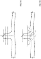
- a perpendicular vein condition (shown in Figures 9A and 9B ) is detected, the i th propagation direction is determined differently than what previously discussed.
- the perpendicular vein condition is verified when the vein branch splits in two vein branches that extend in prosecution between each other, almost along a same direction (i.e., when the vein branch bifurcates in two vein branches substantially forming a T-shaped connection).
- the perpendicular vein condition is detected when the extension of a vein branch, when compared with the respective area of interest, is greater than a threshold; in fact, since the area of interest is determined based on the extension of the vein branch at the previous iteration, having at the current iteration a vein branch that is too big with respect to what can be expected means that the contour seen at the current iteration is actually indicative of the joining section of two vein branches, as shown in Figure 9A .
- the steps of calculating the propagation direction and the consecutive area of interest are repeated by using the following approach: instead of a single propagation direction, a first and a second propagation directions are used at the current iteration for determining respective areas of interest (that are indicative of respective vein branches), as shown in Figure 9B .
- the first and a second propagation directions D 1 and D 2 define default angles ⁇ and ⁇ (opposite to each other) with respect to a direction D ort orthogonal to the current area of interest.
- the angles ⁇ and ⁇ range from about ⁇ 30° to about ⁇ 60°, and for example are equal to about ⁇ 45°.
- a second global cycle of coronary sinus segmentation is carried out to segment the coronary sinus below the starting 2D image 70, thus achieving a complete segmentation of the coronary sinus (i.e., on both sides of the starting 2D image 70) .
- step S62 the identification method 20 ends.
- the training method for the second neural network model is analogous to the training method 40 of Figure 5 , and thus will not be further described.
- the only difference is that the generation of the 2D images is done by creating patches starting from the 3D model 50 and also by generating random 2D patches of different shapes and positions, in a per se known way.
- the identification method 20 allows to implement an automatic recognition of the coronary sinus of the patient 11. This leads to a reduction of time required for such recognition, and to the fact that the identification method 20 can be executed also by operators not specifically trained in segmenting medical images acquired through the CT apparatus 3 (i.e., by operators other than highly trained physicians) .
- the identification method 20 being automatically performed by the computer 5, prevents from human errors, inexperience or negligence that can cause the medical images to be wrongly segmented, with beneficial effects on the health of the patients 11 that can now be correctly diagnosed and thus suitably medically treated.
- the accuracy of recognition of the coronary sinus ranges from about 0.65 to about 1, which is comparable with the accuracy of manual segmentation through visual inspection.
- the medical images can present artifacts such as noise and motion, and the shape of the coronary sinus can vary from patient to patient, as well as its prominence.
- the identification method 20 is robust to noise and motion and takes into account spatial information, due to the presence of the neural networks 22a, 22b, 22c, and therefore is a suitable method for coronary sinus recognition and segmentation.
- a 3D approach can be chosen.
- the segmentation by neural networks can be done through 3D input data instead of 2D ones.
- the architecture is changed from 2D CNN to 3D CNN (e.g. unet3D https://arxiv.org/pdf/1606.06650.pdf; the architecture is the same except that all layers are changed to 3D), the input values for the neural networks are 3D images and the corresponding outputs are 3D prediction masks.
- the prediction can be done either on the whole 3D image (e.g., 512*512*N image) or on overlapped 3D patches. From every input image, overlapping cubes with a specified size and step (e.g., cubes 64*64*64 and step size between these overlapped cubes equal to 32 pixels) can be selected and the resulted prediction is the mask comprising mean or maximum values of the predictions on the cubes (e.g., if several cubes share the same voxel, the output value of the 3D mask in that voxel is the mean or the maximum value of all the predictions).
- overlapping cubes with a specified size and step e.g., cubes 64*64*64 and step size between these overlapped cubes equal to 32 pixels
- the resulted prediction is the mask comprising mean or maximum values of the predictions on the cubes (e.g., if several cubes share the same voxel, the output value of the 3D mask in that vox
- 3D cubes of interest are extracted (e.g., extracting cubes that each comprises the correspondent 2D area of interest, or extracting rotated cubes whose z-axes are parallel to the propagation directions) and used as inputs to the second neural network model outputting a 3D mask, the propagation directions are determined based on this prediction and the steps are repeated.
Landscapes
- Engineering & Computer Science (AREA)
- Health & Medical Sciences (AREA)
- Theoretical Computer Science (AREA)
- Physics & Mathematics (AREA)
- General Physics & Mathematics (AREA)
- Medical Informatics (AREA)
- Computer Vision & Pattern Recognition (AREA)
- Life Sciences & Earth Sciences (AREA)
- Multimedia (AREA)
- General Health & Medical Sciences (AREA)
- Radiology & Medical Imaging (AREA)
- Evolutionary Computation (AREA)
- Nuclear Medicine, Radiotherapy & Molecular Imaging (AREA)
- Surgery (AREA)
- Databases & Information Systems (AREA)
- Biomedical Technology (AREA)
- Heart & Thoracic Surgery (AREA)
- Molecular Biology (AREA)
- Optics & Photonics (AREA)
- Animal Behavior & Ethology (AREA)
- High Energy & Nuclear Physics (AREA)
- Public Health (AREA)
- Veterinary Medicine (AREA)
- Software Systems (AREA)
- Biophysics (AREA)
- Pathology (AREA)
- Computing Systems (AREA)
- Artificial Intelligence (AREA)
- Quality & Reliability (AREA)
- Oral & Maxillofacial Surgery (AREA)
- Dentistry (AREA)
- Cardiology (AREA)
- Image Analysis (AREA)
- Magnetic Resonance Imaging Apparatus (AREA)
- Apparatus For Radiation Diagnosis (AREA)
- Paper (AREA)
- Laser Surgery Devices (AREA)
Applications Claiming Priority (1)
| Application Number | Priority Date | Filing Date | Title |
|---|---|---|---|
| IT102021000016502A IT202100016502A1 (it) | 2021-06-23 | 2021-06-23 | Metodo di segmentazione automatica del seno coronario |
Publications (2)
| Publication Number | Publication Date |
|---|---|
| EP4123581A2 true EP4123581A2 (de) | 2023-01-25 |
| EP4123581A3 EP4123581A3 (de) | 2023-04-19 |
Family
ID=77802009
Family Applications (1)
| Application Number | Title | Priority Date | Filing Date |
|---|---|---|---|
| EP22179913.3A Pending EP4123581A3 (de) | 2021-06-23 | 2022-06-20 | Verfahren zur automatischen segmentierung des sinus coronarius |
Country Status (3)
| Country | Link |
|---|---|
| US (1) | US12354268B2 (de) |
| EP (1) | EP4123581A3 (de) |
| IT (1) | IT202100016502A1 (de) |
Families Citing this family (1)
| Publication number | Priority date | Publication date | Assignee | Title |
|---|---|---|---|---|
| US20250061605A1 (en) * | 2023-08-15 | 2025-02-20 | GE Precision Healthcare LLC | Hybrid 3d-to-2d slice-wise object localization ensembles |
Family Cites Families (7)
| Publication number | Priority date | Publication date | Assignee | Title |
|---|---|---|---|---|
| US6842638B1 (en) * | 2001-11-13 | 2005-01-11 | Koninklijke Philips Electronics N.V. | Angiography method and apparatus |
| WO2014063005A1 (en) * | 2012-10-18 | 2014-04-24 | Washington University | Transcranialphotoacoustic/thermoacoustic tomography brain imaging informed by adjunct image data |
| US9947102B2 (en) * | 2016-08-26 | 2018-04-17 | Elekta, Inc. | Image segmentation using neural network method |
| WO2018078540A1 (en) * | 2016-10-25 | 2018-05-03 | Navix International Limited | Systems and methods for registration of intra-body electrical readings with a pre-acquired three dimensional image |
| US9968257B1 (en) * | 2017-07-06 | 2018-05-15 | Halsa Labs, LLC | Volumetric quantification of cardiovascular structures from medical imaging |
| PL3726460T3 (pl) * | 2019-04-06 | 2024-06-24 | Kardiolytics Inc. | Autonomiczna segmentacja tętnic wieńcowych wypełnionych kontrastem w obrazach tomografii komputerowej |
| US11205264B2 (en) * | 2019-10-15 | 2021-12-21 | GE Precision Healthcare LLC | Systems and methods for multi-label segmentation of cardiac computed tomography and angiography images using deep neural networks |
-
2021
- 2021-06-23 IT IT102021000016502A patent/IT202100016502A1/it unknown
-
2022
- 2022-06-20 EP EP22179913.3A patent/EP4123581A3/de active Pending
- 2022-06-22 US US17/846,311 patent/US12354268B2/en active Active
Also Published As
| Publication number | Publication date |
|---|---|
| IT202100016502A1 (it) | 2022-12-23 |
| US12354268B2 (en) | 2025-07-08 |
| EP4123581A3 (de) | 2023-04-19 |
| US20220414882A1 (en) | 2022-12-29 |
Similar Documents
| Publication | Publication Date | Title |
|---|---|---|
| US12165287B2 (en) | sCT image generation using CycleGAN with deformable layers | |
| US10762637B2 (en) | Vascular segmentation using fully convolutional and recurrent neural networks | |
| JP7039153B2 (ja) | 敵対的生成ネットワークを使用した画像強調 | |
| US10997466B2 (en) | Method and system for image segmentation and identification | |
| CN111008984B (zh) | 医学影像中正常器官的轮廓线自动勾画方法 | |
| CN110517238B (zh) | Ct医学影像ai三维重建与人机交互可视化网络系统 | |
| CN109003267B (zh) | 从3d图像自动检测目标对象的计算机实现方法和系统 | |
| WO2019200753A1 (zh) | 病变监测方法、装置、计算机设备和存储介质 | |
| US11600379B2 (en) | Systems and methods for generating classifying and quantitative analysis reports of aneurysms from medical image data | |
| US20220378383A1 (en) | Target area determination method and medical imaging system | |
| CN103514597A (zh) | 图像处理装置 | |
| La Rosa | A deep learning approach to bone segmentation in CT scans | |
| US12183004B2 (en) | Method and device for extracting blood vessel wall | |
| EP4057221A1 (de) | Multitask-lernsystem zur vollautomatischen beurteilung einer koronararterienerkrankung | |
| EP4123581A2 (de) | Verfahren zur automatischen segmentierung des sinus coronarius | |
| AU2019204365C1 (en) | Method and System for Image Segmentation and Identification | |
| CN112819831A (zh) | 基于卷积Lstm及多模型融合的分割模型生成方法及装置 | |
| Kushnure et al. | DMSAN: Deep Multi‐Scale Attention Network for Automatic Liver Segmentation From Abdomen CT Images | |
| EP4428871B1 (de) | Verfahren zum trainieren eines künstlichen neuronalen netzwerks zur schätzung eines hämodynamischen parameters, verfahren zur schätzung eines hämodynamischen parameters, computerprogrammprodukte und computersysteme | |
| EP4428815A1 (de) | Interaktive bildsegmentierung von abdominalen strukturen | |
| US20240378741A1 (en) | Method and apparatus for detecting and determining the location of objects of interest in an image | |
| US20250372234A1 (en) | Reading error reduction by machine learning assisted alternate finding suggestion | |
| Sharma et al. | Pneumothorax Segmentation from Chest X-Rays Using U-Net/U-Net++ Architectures | |
| WO2024260950A1 (en) | Modifying visibility of anatomical features in medical images | |
| EP4602552A1 (de) | Interaktive bildsegmentierung von abdominalen strukturen |
Legal Events
| Date | Code | Title | Description |
|---|---|---|---|
| PUAI | Public reference made under article 153(3) epc to a published international application that has entered the european phase |
Free format text: ORIGINAL CODE: 0009012 |
|
| STAA | Information on the status of an ep patent application or granted ep patent |
Free format text: STATUS: THE APPLICATION HAS BEEN PUBLISHED |
|
| AK | Designated contracting states |
Kind code of ref document: A2 Designated state(s): AL AT BE BG CH CY CZ DE DK EE ES FI FR GB GR HR HU IE IS IT LI LT LU LV MC MK MT NL NO PL PT RO RS SE SI SK SM TR |
|
| PUAL | Search report despatched |
Free format text: ORIGINAL CODE: 0009013 |
|
| AK | Designated contracting states |
Kind code of ref document: A3 Designated state(s): AL AT BE BG CH CY CZ DE DK EE ES FI FR GB GR HR HU IE IS IT LI LT LU LV MC MK MT NL NO PL PT RO RS SE SI SK SM TR |
|
| RIC1 | Information provided on ipc code assigned before grant |
Ipc: G06T 7/11 20170101AFI20230316BHEP |
|
| STAA | Information on the status of an ep patent application or granted ep patent |
Free format text: STATUS: REQUEST FOR EXAMINATION WAS MADE |
|
| 17P | Request for examination filed |
Effective date: 20231010 |
|
| RBV | Designated contracting states (corrected) |
Designated state(s): AL AT BE BG CH CY CZ DE DK EE ES FI FR GB GR HR HU IE IS IT LI LT LU LV MC MK MT NL NO PL PT RO RS SE SI SK SM TR |
|
| STAA | Information on the status of an ep patent application or granted ep patent |
Free format text: STATUS: EXAMINATION IS IN PROGRESS |
|
| 17Q | First examination report despatched |
Effective date: 20251006 |