EP4428627A1 - Vorrichtung zur autonomen einstellung der aktiven länge einer spiralfeder - Google Patents
Vorrichtung zur autonomen einstellung der aktiven länge einer spiralfeder Download PDFInfo
- Publication number
- EP4428627A1 EP4428627A1 EP24153713.3A EP24153713A EP4428627A1 EP 4428627 A1 EP4428627 A1 EP 4428627A1 EP 24153713 A EP24153713 A EP 24153713A EP 4428627 A1 EP4428627 A1 EP 4428627A1
- Authority
- EP
- European Patent Office
- Prior art keywords
- hairspring
- arm
- active length
- pins
- balance
- Prior art date
- Legal status (The legal status is an assumption and is not a legal conclusion. Google has not performed a legal analysis and makes no representation as to the accuracy of the status listed.)
- Granted
Links
Images

Classifications
-
- G—PHYSICS
- G04—HOROLOGY
- G04B—MECHANICALLY-DRIVEN CLOCKS OR WATCHES; MECHANICAL PARTS OF CLOCKS OR WATCHES IN GENERAL; TIME PIECES USING THE POSITION OF THE SUN, MOON OR STARS
- G04B18/00—Mechanisms for setting frequency
- G04B18/04—Adjusting the beat of the pendulum, balance, or the like, e.g. putting into beat
- G04B18/06—Adjusting the beat of the pendulum, balance, or the like, e.g. putting into beat by setting the collet or the stud of a hairspring
-
- G—PHYSICS
- G04—HOROLOGY
- G04B—MECHANICALLY-DRIVEN CLOCKS OR WATCHES; MECHANICAL PARTS OF CLOCKS OR WATCHES IN GENERAL; TIME PIECES USING THE POSITION OF THE SUN, MOON OR STARS
- G04B17/00—Mechanisms for stabilising frequency
- G04B17/32—Component parts or constructional details, e.g. collet, stud, virole or piton
-
- G—PHYSICS
- G04—HOROLOGY
- G04B—MECHANICALLY-DRIVEN CLOCKS OR WATCHES; MECHANICAL PARTS OF CLOCKS OR WATCHES IN GENERAL; TIME PIECES USING THE POSITION OF THE SUN, MOON OR STARS
- G04B18/00—Mechanisms for setting frequency
- G04B18/02—Regulator or adjustment devices; Indexing devices, e.g. raquettes
- G04B18/023—Regulator or adjustment devices; Indexing devices, e.g. raquettes with means for fine adjustment of the indexing device
-
- G—PHYSICS
- G04—HOROLOGY
- G04B—MECHANICALLY-DRIVEN CLOCKS OR WATCHES; MECHANICAL PARTS OF CLOCKS OR WATCHES IN GENERAL; TIME PIECES USING THE POSITION OF THE SUN, MOON OR STARS
- G04B18/00—Mechanisms for setting frequency
- G04B18/02—Regulator or adjustment devices; Indexing devices, e.g. raquettes
- G04B18/028—Setting the regulator by means coupled to or depending on another device, e.g. by the time indication setting mechanism
Definitions
- the invention relates to an autonomous device for adjusting the active length of a hairspring, for a hairspring-balance type oscillator.
- the invention also relates to a watch movement comprising the autonomous device for adjusting the active length of a hairspring and a balance-spring type oscillator.
- the invention further relates to a timepiece, in particular a watch, comprising the watch movement.
- the outer end of the hairspring is immobilized by a stud fixed to a stud holder secured to a balance cock.
- a rotating indexing device relative to the stud holder is provided to adjust the active length of the hairspring, thus making it possible to adjust the frequency of the sprung balance.
- the indexing device is a lever, generally equipped with two arms, which pivots centered on the coordinate of the balance shaft.
- a first arm of the indexing device carries, for example, two pins between which the hairspring is free.
- a second arm of the indexing device can be manually actuated to pivot the indexing device by a certain angle around the balance shaft. This makes it possible to modify the actual position of the counting point.
- the active length of the hairspring is reduced or increased.
- a disadvantage of such a manual adjustment device is that the Earth's gravity influences the frequency of the oscillations of the sprung balance depending on the orientation of the watch movement. corresponding.
- the rate of a watch may have a significant rate deviation between its horizontal and vertical positions, in particular.
- the oscillations of the balance-spring cause a disturbance of its active length and therefore a slight variation in the frequency of the oscillations of the balance-spring assembly.
- a solution implementing a device for adjusting the active length of the hairspring in which the index carries clamping means intended to clamp a terminal portion of the hairspring to define the active length of the latter.
- the external end of the hairspring is furthermore integral with a fixing system mounted movably relative to the index and arranged to cooperate with the latter.
- the clamping means consisting for example of a pin-eccentric clamping system in which the terminal portion of the hairspring is clamped, can be loosened or tightened at will by a watchmaker.
- the invention therefore aims to provide a device for adjusting the active length of a balance spring, for a balance-spring type oscillator, making it possible to counterbalance in a simple, precise and autonomous manner the effects of gravity, in particular the disturbances of the isochronism of the balance of the oscillator, and overcoming the aforementioned drawbacks of the state of the art.
- the invention relates to a device for autonomously adjusting the active length of a hairspring, for a balance-spring type oscillator, comprising a cock mounted on a plate of a watch movement and in which a balance shaft pivots, the hairspring comprising an internal end secured to the balance shaft and an external end secured to a stud fixed to a stud holder, the stud holder being pivotally mounted on the cock concentrically to the balance shaft, and means for modifying the active length of the hairspring.
- An advantage of the adjustment device according to the invention lies in the fact that it comprises weights mounted to move in translation and cooperating indirectly with a movable arm arranged to act on the coil. external of the balance spring.
- a movement of the weight, freely subjected to gravity thus causes a movement of the arm, between a rest position and a correction position of the device, and simultaneously acts on the balance spring to modify the active length of the balance spring, allowing the latter to be adjusted in order to compensate for the disturbances of the isochronism of the balance due to gravity.
- the adjustment device according to the invention makes it possible to precisely compensate for the rate of the oscillator according to its position in space, by counterbalancing the disturbances of the isochronism of the balance due to gravity, and this autonomously.
- the invention also relates to a watch movement comprising the adjustment device described above, and which comprises the characteristics mentioned in dependent claim 14.
- the invention also relates to a timepiece comprising the watch movement described above, and which comprises the characteristics mentioned in dependent claim 15.
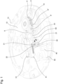
- FIG. 1 represents a part of a timepiece 1, which comprises a watch movement 2.
- the timepiece 1 is a watch.
- the watch movement 2 comprises an oscillator provided with a balance wheel 4 and a hairspring 5, and a device 6 for autonomously adjusting the active length of the hairspring 5.
- the hairspring 5 is fixed to a balance shaft (not visible) by its inner end (not visible).
- the balance shaft has one end pivotally mounted in a balance bridge (the latter not being visible in the figures for clarity).
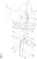
- the outer end of the hairspring 5 is conventionally fixed to a stud 8 fixed to a stud holder 10, the stud holder 10 being secured to a cock 12 by slight tightening. More precisely, the stud holder 10 is pivotally mounted on the cock 12 concentrically to the balance shaft, as illustrated in the figure 2 .
- the balance shaft is pivotally mounted in cock 12.
- the means 6 for modifying the active length of the hairspring 5 are capable of modifying the active length of the hairspring 5 by acting on the length of the external coil of the hairspring 5.
- the means for modifying the active length of the hairspring 5 comprise a first arm 60 capable of moving between a rest position and a correction position of the device, the first arm 60 having a first free end 600 and a second end 601 cooperating with a first pair of pins 19 forming a guide fork for the first arm 60, the first pair of pins 19 being mounted on the stud holder 10 and angularly offset relative to the stud 8 via a first support 8'.
- the position of the first support 8' can be modified radially relative to the stud holder 10.
- the second end 601 of the arm 60 can slide between the two pins 19 and comes into contact with the outer coil of the hairspring 5 in the correction position to modify the active length of the hairspring.
- the means 6 for modifying the active length of the hairspring also comprise a pair of linear weights 40, 41 movable in translation in orthogonal planes so that they are superimposed and do not come into contact during their movements.
- the weights 40, 41 are arranged to move in translation as a function of gravity, the movement of at least one of the weights 40, 41 rotating a shaft 20 on which a first cam 30 and a second cam 31 are mounted.
- the rotation of the first cam 30 causes a movement of the first arm 60 to act on the hairspring and simultaneously modify the active length of the hairspring 5, and the same is true for the second cam 31 which is arranged to cooperate with the second arm 61.
- each of the weights 40, 41 is in the form of a linear body having two guide grooves 400, 401, 410, 411 extending over the length of each weight and arranged on opposite faces of each weight.
- the weights are arranged to slide each in a guide element 50, 51, each guide element comprising rails arranged to cooperate with the guide grooves 400, 401, 410, 411 and guide the weights in translation.
- the guide elements 50, 51 are integral with the plate 13 of the movement and comprise elastic return means configured to exert an elastic return action in position on the weights 40, 41.
- These elastic return means are in the form of a pair of spring blades 520, 521, arranged at the distal ends of the guide elements 50, 51 so as to pinch each weight 40, 41 by its ends and thus accompany the movements of each weight and then return them to their original position when the watch returns to a rest position (i.e. a position where the weights are not freely subjected to gravity).
- the spring blades 520, 521 also form damping means and make it possible to avoid a sudden movement of the weights 40, 41, and therefore to limit, or even prevent, the modification of the active length of the balance spring 5 during a sudden acceleration or deceleration.
- the adjustment device also comprises a second arm 61 capable of moving between a rest position and a correction position of the device, the second arm 61 having a first free end 610 and a second end cooperating with a second pair of pins 19' forming a guide fork for the second arm 61, the second pair of pins 19' being mounted on the stud holder 10 and angularly offset relative to the stud and to the first pair of pins 19 via a second support 8".
- the position of the second support 8" can be modified radially relative to the stud holder 10.
- the second end 611 of the second arm 61 can slide between the two pins 19' and comes into contact with the outer turn of the balance spring in the correction position to modify the active length of the balance spring.
- the engagement means also comprise a second cam 31 arranged to cooperate with the second arm, the free end 610 of which rests against the second cam 31.
- the adjustment device comprises elastic constraint means configured to exert an elastic return action in position on the arms 60, 61.
- the elastic constraint means are in the form of a rod 62 secured to the arm 60 and a spring blade 63 secured to the stud holder 10, the spring blade 61 exerting a return force on the rod 62 and exerting an elastic return action in position on the arm 60.
- Elastic constraint means are also associated with the second arm 61, and comprise a rod 64 secured to the second arm 61 and a spring blade 65 secured to the stud holder 10, the spring blade 65 exerting a return force on the rod 64 and exerting an elastic return action in position on the second arm 61.
- the adjustment device 6 also comprises means for adjusting the arms 60, 61, the free end 600, 610 of the first and second arms 60, 61 comprising elastically deformable adjustment means for lengthening or shortening the length of the arms.
- the adjustment means are in the form of a spring blade, a first end of which is secured to the arm and another end is free, the free end being arranged to be placed under stress and adjust the length of the arms 60, 61, the spring blade forming a space between it and the free end of each arm. Such an adjustment is necessary depending on the position of the hairspring and the correction to be made to the latter.
- each arm 60, 61 comprises means for adjusting the elastic stress, the adjustment means being in the form of a screw 70, 71, each screw passing through the free end of the spring blade and bearing against the arm.
- the adjustment means being in the form of a screw 70, 71, each screw passing through the free end of the spring blade and bearing against the arm.
- the weights 40, 41 are free to move in translation, each in their plane, and within the travel limit imposed by the spring blades 520, 521.
- Each weight 40, 41 comprises a toothed sector 402, 412 which is arranged to mesh with a respective pinion 21, 22 of the axis 20 on which the cams 30 and 31 are mounted so that a movement of at least one of the weights 40, 41 causes a movement of at least one of the arms 60, 61 and acts simultaneously on the means for modifying the active length of the balance spring 5.
- the movement of the arms under the effect of the movement of the weights 40, 41 subjected to gravity is carried out between a rest position of the device, and a correction position of the device, each of the arms allowing a distinct correction according to the position of the watch.
- the weights 40, 41 freely subjected to gravity, can move in their plane and cause a movement of the arms 60, 61.
- the movement of the weights 40, 41 makes it possible to act simultaneously on the means for modifying the active length of the balance spring 5, and thus to continuously adjust the active length of the balance spring in order to compensate for the disturbances of the isochronism of the balance wheel due to gravity.
- the cams are integral with the shaft 20 and are each respectively in contact with the free end 600, 610 of the arms 60, 61.
- the position of the cams relative to each other is variable depending on the correction to be made to the balance spring, the cams being able to be angularly offset relative to each other, just as they can be in an identical position.
- each cam 30, 31 is a radial cam with an external profile.
- radial cams with a substantially rectangular external profile are shown in the Figures 1 to 3 , in practice the shape envisaged for the external profile of each cam will depend on the type of spiral 5 used and the correction to be made to it.
- a radial cam with a triangular, oblong or even ovoid external profile can also be used in the context of the present invention.
- a flat portion of each cam is in contact with an arm 60, 61, while in the correction position of the device 6, a corner or an angle of the cam 30, 31 is in contact with the arm 60, 61. More preferably, as visible in the figures 1 , 3 and 4, each cam 30, 31 is in contact with its respective arm whatever the position of the weight 40.
- the weights 40, 41 freely subjected to gravity, can slide in their plane and cause a movement of the arms 60, 61.
- the movement of the weights makes it possible to act simultaneously on the means for modifying the active length of the balance spring 5, making it possible to continuously adjust the active length of the balance spring in order to compensate for the disturbances of the isochronism of the balance wheel due to gravity.
- the movement of the weights 40, 41 causes a rotation of the shaft 20 via the cooperation of the toothed sectors 402, 412 with the pinions 20, 21 of the shaft 20 and has the effect of driving the cams 30, 31 which are integral with the shaft, the cams then acting on the free end 600, 610 of the arms 60, 61 and moving at least one of the arms 60, 61 so that the second end of one of the arms comes into contact with the balance spring 5 so as to modify the active length of the balance spring 5.
- the device will return to the rest position by itself thanks to the action of the spring blades 520, 521 on the weights 40, 41.
- the invention also relates to a watch movement 2 comprising an oscillator 4, 5 of the balance-spring type and a device 6 for autonomous adjustment of the active length of the balance spring 5 as described previously.
- the invention also relates to a timepiece 1 comprising a watch movement 2 provided with a device 6 for autonomous adjustment of the active length of the hairspring 5 as described previously.
Landscapes
- Physics & Mathematics (AREA)
- General Physics & Mathematics (AREA)
- Transmission Devices (AREA)
- Electric Clocks (AREA)
- Electromechanical Clocks (AREA)
Applications Claiming Priority (1)
| Application Number | Priority Date | Filing Date | Title |
|---|---|---|---|
| EP23160134.5A EP4428625A1 (de) | 2023-03-06 | 2023-03-06 | Vorrichtung zur autonomen einstellung der aktiven länge einer spiralfeder |
Publications (2)
| Publication Number | Publication Date |
|---|---|
| EP4428627A1 true EP4428627A1 (de) | 2024-09-11 |
| EP4428627B1 EP4428627B1 (de) | 2025-12-03 |
Family
ID=85505393
Family Applications (2)
| Application Number | Title | Priority Date | Filing Date |
|---|---|---|---|
| EP23160134.5A Withdrawn EP4428625A1 (de) | 2023-03-06 | 2023-03-06 | Vorrichtung zur autonomen einstellung der aktiven länge einer spiralfeder |
| EP24153713.3A Active EP4428627B1 (de) | 2023-03-06 | 2024-01-24 | Vorrichtung zur autonomen einstellung der aktiven länge einer spiralfeder |
Family Applications Before (1)
| Application Number | Title | Priority Date | Filing Date |
|---|---|---|---|
| EP23160134.5A Withdrawn EP4428625A1 (de) | 2023-03-06 | 2023-03-06 | Vorrichtung zur autonomen einstellung der aktiven länge einer spiralfeder |
Country Status (4)
| Country | Link |
|---|---|
| US (1) | US20240302796A1 (de) |
| EP (2) | EP4428625A1 (de) |
| JP (1) | JP7642885B2 (de) |
| CN (1) | CN118605103A (de) |
Families Citing this family (1)
| Publication number | Priority date | Publication date | Assignee | Title |
|---|---|---|---|---|
| EP4715484A1 (de) * | 2024-09-20 | 2026-03-25 | Patek Philippe Sa Geneve | Uhrvorrichtung mit unruhspiralfeder und mittel zur einstellung der liegend-hängend |
Citations (3)
| Publication number | Priority date | Publication date | Assignee | Title |
|---|---|---|---|---|
| DE1631889U (de) * | 1951-06-23 | 1951-12-06 | August Ehrenfried | Verstiftung und anordnung der unruhspiralfeder. |
| CH705605B1 (fr) | 2011-10-14 | 2016-10-14 | Frederique Constant S A | Dispositif de réglage de la longueur active d'un spiral. |
| EP3502788A1 (de) * | 2017-12-20 | 2019-06-26 | The Swatch Group Research and Development Ltd | Vorrichtung zur selbstregulierung der aktiven länge einer spirale |
-
2023
- 2023-03-06 EP EP23160134.5A patent/EP4428625A1/de not_active Withdrawn
-
2024
- 2024-01-24 EP EP24153713.3A patent/EP4428627B1/de active Active
- 2024-01-30 US US18/427,050 patent/US20240302796A1/en active Pending
- 2024-02-08 JP JP2024017668A patent/JP7642885B2/ja active Active
- 2024-03-06 CN CN202410255044.2A patent/CN118605103A/zh active Pending
Patent Citations (3)
| Publication number | Priority date | Publication date | Assignee | Title |
|---|---|---|---|---|
| DE1631889U (de) * | 1951-06-23 | 1951-12-06 | August Ehrenfried | Verstiftung und anordnung der unruhspiralfeder. |
| CH705605B1 (fr) | 2011-10-14 | 2016-10-14 | Frederique Constant S A | Dispositif de réglage de la longueur active d'un spiral. |
| EP3502788A1 (de) * | 2017-12-20 | 2019-06-26 | The Swatch Group Research and Development Ltd | Vorrichtung zur selbstregulierung der aktiven länge einer spirale |
Also Published As
| Publication number | Publication date |
|---|---|
| CN118605103A (zh) | 2024-09-06 |
| EP4428627B1 (de) | 2025-12-03 |
| JP2024126007A (ja) | 2024-09-19 |
| EP4428625A1 (de) | 2024-09-11 |
| JP7642885B2 (ja) | 2025-03-10 |
| US20240302796A1 (en) | 2024-09-12 |
Similar Documents
| Publication | Publication Date | Title |
|---|---|---|
| EP3502788B1 (de) | Vorrichtung zur selbstregulierung der aktiven länge einer spirale | |
| EP4009115A1 (de) | Spiralfeder für resonatormechanismus eines uhrwerks, der mit mitteln zum ausgleichen der starrheit ausgestattet ist | |
| CH709052B1 (fr) | Balancier-spiral, mouvement et pièce d'horlogerie. | |
| EP4016194A1 (de) | Resonatormechanismus eines uhrwerks mit flexibler führung, die mit mitteln zur einstellung der steifigkeit ausgestattet ist | |
| EP4428627B1 (de) | Vorrichtung zur autonomen einstellung der aktiven länge einer spiralfeder | |
| CH718113B1 (fr) | Ressort-spiral pour mécanisme résonateur d'horlogerie muni de moyens d'ajustement de la rigidité | |
| EP3430479B1 (de) | Vorrichtung für eine uhr, uhrwerk und uhr mit solch einer vorrichtung | |
| EP3338144B1 (de) | Bistabile mechanische vorrichtung für uhrwerke | |
| EP4286961A1 (de) | Uhrregulierungsorgan mit einer präzisionsrückervorrichtung | |
| EP4428626B1 (de) | Vorrichtung zur autonomen einstellung der aktiven länge einer spiralfeder | |
| CH720584A2 (fr) | Dispositif de réglage autonome de la longueur active d'un spiral | |
| EP4428628B1 (de) | Vorrichtung zur autonomen einstellung der aktiven länge einer spiralfeder | |
| EP4428624B1 (de) | Vorrichtung zur autonomen einstellung der aktiven länge einer spiralfeder | |
| CH720583A2 (fr) | Dispositif de réglage autonome de la longueur active d'un spiral | |
| CH720580A2 (fr) | Dispositif de réglage autonome de la longueur active d'un spiral | |
| CH720582A2 (fr) | Dispositif de réglage autonome de la longueur active d'un spiral | |
| EP4432020A1 (de) | Uhrwerk | |
| EP4498174A1 (de) | Regulierorgan für uhren, das ein betätigungssystem mit einer steuerwippe umfasst | |
| EP4498176A1 (de) | Regulierungsorgan für uhren, das mit einem linearem betätigungssystem augerustet ist | |
| EP4521173A1 (de) | Uhrvorrichtung | |
| EP4498175A1 (de) | Uhreinstellorgan mit hakenbetätigungssystem | |
| CH720978A2 (fr) | Système d'actionnement micromécanique à guidage flexible pour l'horlogerie | |
| EP4498178A1 (de) | Mikromechanisches betätigungssystem mit flexibler führung für die uhr | |
| CH720982A2 (fr) | Organe réglant d'horlogerie comprenant un système d'actionnement muni d'une bascule de commande | |
| CH721359A2 (fr) | Balancier à inertie variable |
Legal Events
| Date | Code | Title | Description |
|---|---|---|---|
| PUAI | Public reference made under article 153(3) epc to a published international application that has entered the european phase |
Free format text: ORIGINAL CODE: 0009012 |
|
| STAA | Information on the status of an ep patent application or granted ep patent |
Free format text: STATUS: THE APPLICATION HAS BEEN PUBLISHED |
|
| AK | Designated contracting states |
Kind code of ref document: A1 Designated state(s): AL AT BE BG CH CY CZ DE DK EE ES FI FR GB GR HR HU IE IS IT LI LT LU LV MC ME MK MT NL NO PL PT RO RS SE SI SK SM TR |
|
| STAA | Information on the status of an ep patent application or granted ep patent |
Free format text: STATUS: REQUEST FOR EXAMINATION WAS MADE |
|
| P01 | Opt-out of the competence of the unified patent court (upc) registered |
Free format text: CASE NUMBER: APP_6838/2025 Effective date: 20250210 |
|
| 17P | Request for examination filed |
Effective date: 20250311 |
|
| GRAP | Despatch of communication of intention to grant a patent |
Free format text: ORIGINAL CODE: EPIDOSNIGR1 |
|
| STAA | Information on the status of an ep patent application or granted ep patent |
Free format text: STATUS: GRANT OF PATENT IS INTENDED |
|
| INTG | Intention to grant announced |
Effective date: 20250811 |
|
| GRAS | Grant fee paid |
Free format text: ORIGINAL CODE: EPIDOSNIGR3 |
|
| GRAA | (expected) grant |
Free format text: ORIGINAL CODE: 0009210 |
|
| STAA | Information on the status of an ep patent application or granted ep patent |
Free format text: STATUS: THE PATENT HAS BEEN GRANTED |
|
| AK | Designated contracting states |
Kind code of ref document: B1 Designated state(s): AL AT BE BG CH CY CZ DE DK EE ES FI FR GB GR HR HU IE IS IT LI LT LU LV MC ME MK MT NL NO PL PT RO RS SE SI SK SM TR |
|
| REG | Reference to a national code |
Ref country code: CH Ref legal event code: F10 Free format text: ST27 STATUS EVENT CODE: U-0-0-F10-F00 (AS PROVIDED BY THE NATIONAL OFFICE) Effective date: 20251203 Ref country code: GB Ref legal event code: FG4D Free format text: NOT ENGLISH |
|
| REG | Reference to a national code |
Ref country code: CH Ref legal event code: R17 Free format text: ST27 STATUS EVENT CODE: U-0-0-R10-R17 (AS PROVIDED BY THE NATIONAL OFFICE) Effective date: 20251217 |
|
| REG | Reference to a national code |
Ref country code: DE Ref legal event code: R096 Ref document number: 602024001441 Country of ref document: DE |
|
| REG | Reference to a national code |
Ref country code: IE Ref legal event code: FG4D Free format text: LANGUAGE OF EP DOCUMENT: FRENCH |