EP4428362A1 - Windturbinenblatt mit integriertem blitzschutzsystem - Google Patents
Windturbinenblatt mit integriertem blitzschutzsystem Download PDFInfo
- Publication number
- EP4428362A1 EP4428362A1 EP23168171.9A EP23168171A EP4428362A1 EP 4428362 A1 EP4428362 A1 EP 4428362A1 EP 23168171 A EP23168171 A EP 23168171A EP 4428362 A1 EP4428362 A1 EP 4428362A1
- Authority
- EP
- European Patent Office
- Prior art keywords
- spar cap
- spar
- conductor
- cross
- sectional area
- Prior art date
- Legal status (The legal status is an assumption and is not a legal conclusion. Google has not performed a legal analysis and makes no representation as to the accuracy of the status listed.)
- Granted
Links
Images


Classifications
-
- F—MECHANICAL ENGINEERING; LIGHTING; HEATING; WEAPONS; BLASTING
- F03—MACHINES OR ENGINES FOR LIQUIDS; WIND, SPRING, OR WEIGHT MOTORS; PRODUCING MECHANICAL POWER OR A REACTIVE PROPULSIVE THRUST, NOT OTHERWISE PROVIDED FOR
- F03D—WIND MOTORS
- F03D1/00—Wind motors with rotation axis substantially parallel to the air flow entering the rotor
- F03D1/06—Rotors
- F03D1/065—Rotors characterised by their construction elements
- F03D1/0675—Rotors characterised by their construction elements of the blades
-
- F—MECHANICAL ENGINEERING; LIGHTING; HEATING; WEAPONS; BLASTING
- F03—MACHINES OR ENGINES FOR LIQUIDS; WIND, SPRING, OR WEIGHT MOTORS; PRODUCING MECHANICAL POWER OR A REACTIVE PROPULSIVE THRUST, NOT OTHERWISE PROVIDED FOR
- F03D—WIND MOTORS
- F03D80/00—Details, components or accessories not provided for in groups F03D1/00 - F03D17/00
- F03D80/30—Lightning protection
-
- F—MECHANICAL ENGINEERING; LIGHTING; HEATING; WEAPONS; BLASTING
- F05—INDEXING SCHEMES RELATING TO ENGINES OR PUMPS IN VARIOUS SUBCLASSES OF CLASSES F01-F04
- F05B—INDEXING SCHEME RELATING TO WIND, SPRING, WEIGHT, INERTIA OR LIKE MOTORS, TO MACHINES OR ENGINES FOR LIQUIDS COVERED BY SUBCLASSES F03B, F03D AND F03G
- F05B2280/00—Materials; Properties thereof
- F05B2280/20—Inorganic materials, e.g. non-metallic materials
- F05B2280/2006—Carbon, e.g. graphite
-
- F—MECHANICAL ENGINEERING; LIGHTING; HEATING; WEAPONS; BLASTING
- F05—INDEXING SCHEMES RELATING TO ENGINES OR PUMPS IN VARIOUS SUBCLASSES OF CLASSES F01-F04
- F05B—INDEXING SCHEME RELATING TO WIND, SPRING, WEIGHT, INERTIA OR LIKE MOTORS, TO MACHINES OR ENGINES FOR LIQUIDS COVERED BY SUBCLASSES F03B, F03D AND F03G
- F05B2280/00—Materials; Properties thereof
- F05B2280/60—Properties or characteristics given to material by treatment or manufacturing
- F05B2280/6001—Fabrics
-
- Y—GENERAL TAGGING OF NEW TECHNOLOGICAL DEVELOPMENTS; GENERAL TAGGING OF CROSS-SECTIONAL TECHNOLOGIES SPANNING OVER SEVERAL SECTIONS OF THE IPC; TECHNICAL SUBJECTS COVERED BY FORMER USPC CROSS-REFERENCE ART COLLECTIONS [XRACs] AND DIGESTS
- Y02—TECHNOLOGIES OR APPLICATIONS FOR MITIGATION OR ADAPTATION AGAINST CLIMATE CHANGE
- Y02E—REDUCTION OF GREENHOUSE GAS [GHG] EMISSIONS, RELATED TO ENERGY GENERATION, TRANSMISSION OR DISTRIBUTION
- Y02E10/00—Energy generation through renewable energy sources
- Y02E10/70—Wind energy
- Y02E10/72—Wind turbines with rotation axis in wind direction
Definitions
- the present invention relates to wind turbine blades integrating a lightning protection system.
- An object of the invention is the provision of wind turbine blade integrating a lightning protection system, that reduces manufacturing cost and complexity.
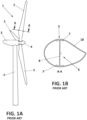
- a wind turbine (1) typically includes a tower (2), a nacelle (3) supported by the tower (2), a hub (4) installed at the nacelle (3), and several blades (5) attached to the hub (4).
- each blade (5) is formed by an outer shell (18) and at least one beam (6) formed by a web (8) and two spar caps (7,7') joined to the web's edges, such that the beam (6) is attached internally to the shell (18) by means of the two spar caps (7,7') .
- Lightning is likely to strike wind turbines blades due to their exposed location and height. As lightning strikes may cause considerable damage to a wind turbine, wind turbines incorporate lightning protection system designed to prevent lightning from damaging the wind turbine blades, bearings and electrical systems of the wind turbine.
- lightning protection systems for wind turbine blades include metallic down conductors attached to a beam of the wind turbine blade, and extending longitudinally from the blade's tip to its root at which the wind turbine blade is attached to a hub.
- additional down-conductors running from the hub via the nacelle and through the tower, lightning currents are conducted to ground.
- EP-3943745 A1 describes a carbon pultruded blade carbon beam comprising a stack of carbon pultruded layers having at least a bottom layer and a top layer, each layer having a first end and a second end.
- the stack defining a tip-region, a root-region, and a mid-region; at least one lightning conductor extending along said stack from the tip-region to the root-region; and a plurality of electrical connections connecting said stack of layers with said lightning conductor, each end of each layer is electrically connected with the lightning conductor by one of said electrical connections; and each electrical connection that connects one of the ends of the top layer with the lightning conductor is electrically connected with the bottom layer.
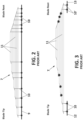
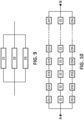
- a carbon spar cap (7) is formed by a plurality of stacked carbon planks or plates (11) having tapered ends, and a down-conductor (9) consisting of a cable running along the spar cap (7) from the root end to the tip end. Electrical connections (10) are provided connecting all the chamfer ends of the carbon planks or plates (11) to the down-conductor (9) .
- any electrical connection (10) at tip needs to have a length of about 10-20 meters to reach the 50% of the maximum carbon spar cap cross-section.
- the electrical connection is just few meters, where the cross-section of the spar cap is below the 50% of the maximum cross-section at the mid-span region of the spar cap, then there is a risk of electric sparks in the rest of the carbon planks at the locations marked in Figure 3 , because lightning current would circulate from a carbon plank to adjacent carbons planks through the ends thereof, that might cause delamination of the planks due to electric arcing.
- the invention is based on the fact that down-conductors for conducting lightning current, are only needed to some extent at root and tip regions of a carbon spar cap for the conduction of current through those regions, but a down-conductor is not required at a mid-span region of the spar cap, because lightning current can circulate through the carbon spar cap mid-region without down-conductor at that region, that is, the carbon plates at a mid-region can act as down-conductor.
- an aspect of the invention refers to a wind turbine blade integrating a lightning protection system, wherein the wind turbine blade has at least one internal carbon beam to reinforce the blade.
- the carbon beam is composed by a web and two spar caps which are formed by a plurality of electrically conductive carbon plates or laminates stacked together, such that the stack of carbon plates has a bottom plate, a top plate, and a plurality of intermediate plates stacked in between the bottom and top plates.
- Each spar cap is an elongated body extending along an axis (X), and extending between a spar cap's root end and spar cap's tip end, so that the spar cap has a blade tip region, a blade root region and a blade mid region in between the blade tip and root regions.
- Each carbon plate has a root end, which is the end closer to the spar cap's root end, and a tip end which is the end closer to the spar cap's tip end.
- the carbon plates ends are tapered ends, that is, they have the shape of a chamfer.
- the wind turbine blade spar cap further comprises a first down-conductor placed alongside the tip region, and a plurality of electric conductors connecting the first down-conductor to some of the tip ends of the carbon plates, and a second down-conductor placed alongside the root region, and a plurality of electric conductors connecting the second down-conductor to some of the root ends of the carbon plates.
- the first down-conductor extends from the spar cap's tip end towards the beam's mid region, and terminates at an end of the first down-conductor located adjacent a first region of the spar cap which extends from a cross-sectional area of the spar cap which area is equal or higher than 75% of the maximum cross-sectional area of the spar cap, being that area the one closest to the spar cap's tip end, to a cross-sectional area of the spar cap which area is 100% of the cross-sectional area of the spar cap, being that 100% of the cross-sectional area the one closest to the spar cap's root end.
- the second down-conductor extends from the spar cap's root end towards the spar cap's mid region, and terminates at an end of the second down-conductor located adjacent a second region of the spar cap which extends from a cross-sectional area of the spar cap which area is equal or higher than 75% of the maximum cross-sectional area of the spar cap, being that area the one closest to the spar cap's root end, to a cross-sectional area of the spar cap which area is 100% of the cross-sectional area of the spar cap, being that 100% of the cross-sectional area the one closest to the spar cap's tip end.
- the invention relies on the fact that, even if carbon fibers of the carbon plates are worst conductors of electrical currents than copper conductors, due to the large cross-sectional area of the beam at a mid-span region thereof, the impedance of that mid region is lower than the one for the down conductor, so that lightning current would flow through the mid region of the spar cap, thus, a down-conductor is not required at that mid-region, which implies that the length of the first and second down-conductors can be reduced.
- the number of electric connections connecting the down-conductor to the carbon plates ends can also be reduced. Therefore, in a preferred embodiment of the invention, at least the top carbon plate of the stack of plates, is not electrically connected by means of an electric conductor to the first or to the second down conductors, so that a lightning strike current would flow from the first down-conductor to an intermediate carbon plate, and from that intermediate carbon plate to the top carbon plate, and from the top carbon plate to the second down conductor via an intermediate carbon plate.
- the first down-conductor extends from the spar cap's tip end to a plane orthogonal to the spar cap which passes through the end of the top carbon plate which is closest to the spar cap's tip end. All the carbon plates have their tip end connected to the first down-conductor.
- the second down-conductor extends from the spar cap's root end to a plane orthogonal to the spar cap which passes through the end of the top carbon plate which is closest to the spar cap's root end. All the carbon plates have their root end connected to the first down conductor.
- the first and the second down-conductors are generally straight conductors running parallel to the axis (X) along which the spar cap extends.
- the wind turbine blade comprises two spar caps, each spar cap constructed as defined in any of the embodiments described above.
- the wind turbine blade has a lightning receptor at the tip of the beam having two spar caps, and a root terminal at the root end.
- the two down-conductors of the tip region of the two spar caps are connected at one end to the lightning receptor, and the two down-conductors of the root region of the two spar caps are connected at one end to the root terminal.
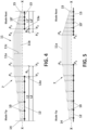
- Figure 4 shows a preferred embodiment of the invention, in particular a spar cap (7) of a wind turbine blade, wherein the spar cap (7) conventionally extends from a spar cap's root end (15) to a spar cap's tip end (14), and it is formed by a plurality of carbon plates stacked together, each carbon plate having a tapered root end and a tapered tip end.
- the stack (11) of carbon plates has a top plate (11a), a bottom plate (11b) and a plurality of intermediate plates (11c) stacked in between the top and bottom plates (11a,11b).
- the spar cap (7) is an elongated body that extends along an axis (X), wherein conventionally a blade tip region, a blade root region and a blade mid region in between the blade tip and root regions, are defined.
- the wind turbine blade comprises a first down-conductor (12) placed alongside the tip region of the spar cap, and a first set of electric conductors (10) connecting the first down-conductor (12) to some of the tip ends of the carbon plates (11a,11b,11c), and a second down-conductor (13) placed alongside the root region of the spar cap, and a second set of electric conductors (10') connecting the second down-conductor (13) to some of the roots ends of the carbon plates (11a,11b,11c).
- the first down-conductor (12) extends from the tip end (14) of the spar cap (7) towards the spar cap's mid region, and it has a length which is longer or equal than a length (L1) and which is equal or shorter than a length (L2).
- the length (L1) starts at the tip end (14) of the spar cap and terminates at a spar cap position or radius where the cross-sectional area in that radius of the spar cap (7) is equal or larger than 75% of the maximum cross-sectional area of the spar cap (7).
- the length (L2) also starts at the tip end (14) and terminates at a spar cap position or radius where the cross-sectional area is 100% of the maximum cross-sectional area of the spar cap (7) and which is closer to the blade's tip end (14).
- the second down-conductor (13) extends from the root end (15) of the spar cap towards the spar cap's mid region, and it has as length equal or longer than (L1') and equal or shorter than a length (L2').
- the length (L1') starts at the root end (15) and terminates at a carbon spar cap position or radius where the cross-sectional area in that radius of the spar cap is equal or larger than 75% of the maximum cross-sectional area of the spar cap (7).
- the length (L2') also starts at the root end (15) and terminates at the carbon spar cap position or radius, where the cross-sectional area is 100% of the maximum cross-sectional area of the spar cap, and which is closer to the root end (15).
- the first and second down-conductors (12,13) are preferably made of cooper having a 50 mm2 cross-sectional area. With the above-described range of length of the first and second down-conductor (12,13), the electrical impedance of a region of the spar cap for which no down-conductor is provided, must be lower than the impedance of a 50 mm2 copper conductor, which is the impedance of the first and second down-conductors (12,13).
- the first and second down-conductors (12,13) are straight conductors that are arranged parallel to the axis (X), and are electrically connected respectively to all or some of the tip ends of the carbon plates (11a,11b,11c) by means of the first set of conductors (10), and to all or some of the root ends of the carbon plates (11a,11b,11c) by means of the second set of conductors (10').
- first down-conductor (12) extends from the spar cap's tip end (14) towards the spar cap's mid region, and terminates at a first down-conductor's end (12a) located adjacent or within a first region (R1) of the spar cap (7).
- This first region (R1) is a region of the spar cap that extends between a first plane (P1) and a second plane (P2), wherein the first plane (P1) is a plane orthogonal to the axis (X) at which the cross-sectional area of the spar cap (7) at this first plane (P1) is equal or higher than 75% of the maximum cross-sectional area of the spar cap and which is the one closest to the spar cap's tip end (14).
- the second plane (P2) is a plane orthogonal to the axis (X), and at which the cross-sectional area of the spar cap at this second plane (P2) is 100% of the cross-sectional area of the spar cap, and which area is closest to the spar cap's tip end (14) .
- the second down-conductor (13) extends from the spar cap's root end (15) towards the spar cap's mid region, and terminates at a second down-conductor's end (13a) located adjacent or within a second region (R2) of the spar cap (7).
- This second region (R2) is a region of the spar cap that extends between a third plane (P3) and a fourth plane (P4), wherein the third plane (P3) is orthogonal to the axis (X) at which the cross-sectional area of the spar cap (7) at this third plane (P3) is equal or higher than 75% of the maximum cross-sectional area of the spar cap and which is the one closest to the spar cap's root end (15).
- the fourth plane (P4) is a plane orthogonal to the axis (X), and at which the cross-sectional area of the par cap at this fourth plane (P4) is 100% of the cross-sectional area of the spar cap and which is the one closest to the spar cap's root end (15).
- the first down-conductor (12) extends from the spar cap's tip end (14) to a plane (P5) orthogonal to the spar cap's axis (X), which passes through the end of the top carbon plate (11a) which is closest to the spar cap's tip end (14).
- the second down-conductor (13) extends from the spar cap's root end (15) to a plane (P6) orthogonal to the spar cap's axis (X), which passes through the end of the top carbon plate (11a) which is closest to the spar cap's root end (15).
- all the carbon plates (11a,11b,11c) have their tip end connected to the first down-conductor (12), and their root end connected to the second down conductor (13), respectively by means of first and second sets (10,10') of electric conductors.
- At least the top carbon plate (11a), and optionally one or more of the intermediate plates (11c), are not connected by means of a conductor to the first or to the second down-conductors (12,13).
- the length of the first and the second down-conductors (12,13), comply with the definition given above in relation to Figure 4 .
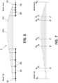
- Figure 8 shows the invention applied to a full blade, that is, having one carbon beam comprising a pressure spar cap and a suction spar cap.
- this particular embodiment comprising two spar caps, namely a first spar cap (7) and a second spar cap (7'), each spar cap constructed as shown in any of the Figures 4, 5 and 6 and as described above in relation to any of those figures or any combination thereof.
- the first spar cap (7) is constructed as shown in Figure 5 and as described above in relation to Figure 5
- the second spar cap (7') is constructed as shown in Figure 6 and as described above in relation to Figure 6 .
- the embodiment of Figure 8 includes a lightning receptor (16) installed nearby the blade tip from the beam tip end, and a root terminal (17) installed nearby the blade root from the beam root end.
- the two down-conductors (12,12') of the tip region of the spar caps (7,7') are connected at one end to the lightning receptor (16) by means of additional metallic conductors (19,19'), and the two down-conductors (13,13') of the root region of the spar caps (7,7') are connected at one end to the root terminal (17) by means of additional metallic conductors (20,20'), as shown in Figure 8 .
- a lightning strike would penetrate through the lightning receptor (16), and would circulate through the down-conductors, mid region of the spar caps (7,7'), and through the root terminal (17).
- Figure 7 in combination with Tables 1 and 2 below, provide some figures on the dimensions in which the cross-sectional area of the spar cap reaches ⁇ 75%, and 100% from the tip and from the root, as defined above.
- Table 1 Radius: Cross-section respect maximum carbon spar cap cross-section [%] R0 & R6 0% R1 85% R2 100% R3 100% R4 85% R5 28.5%
- Table 2 Radius: Length [m] Percentage of the carbon spar cap length [%] R0-R1 3-10 5-10% R0-R2 10-15 10-15% R2-R3 30-60 50-60% R6-R5 2-6 3-7% R6-R4 15-30 25-35% R6-R3 20-40 35-50%
- a metallic main down-conductor has a cross-section of 50 mm2, and the carbon plates as described above, specially at tip region have a total cross-section of about 1000 mm2 multiplied by the number of carbon plates.
- the resistivities of both materials are approximately: Cu: 1.66E-08 Ohm ⁇ m, and Carbon: 2.30E-05 Ohm ⁇ m, it leads to a resistance (R) per meter in each case for a 50 mm2 Copper cable and 1000 mm2 carbon plate of about: R Cu 0.000333 Ohm/m R Carbon 0.02300 Ohm/m
- the impedance is an electrical parameter which depends on the frequency. Basically, in lightning frequencies (up to 1 MHz) the impedance is mainly affected by the contribution of the resistance and the self-inductance of the conductors.
- Z2 is a constant impedance [Q/m], while the different longitudinal segments of impedances Z1 and Z3 change along the blade. Therefore, in general for standard carbon blades, it leads to the condition shown in Figure 11 of the impedance for a reference frequency of 25 kHz.
- the linear impedance of the carbon beam is lower than the one of the down-conductor, which means that most of the lightning current flows through the carbon beam, and the down-conductor may be removed at the mid-span region, in particular at a region between X1 and X2.
- the metallic cable to inject the lightning current into the carbon spar cap may have a length ⁇ L1 and ⁇ L2 being L1 the length in which the carbon spar cap has a cross-section of ⁇ 75% of the maximum spar cap cross-section and L1 a value of 100%, or have a length ⁇ L1' and ⁇ L2' being L1' the length in which the carbon spar cap has a cross-section of ⁇ 75% of the maximum spar cap cross-section and L1' a value of 100%, as defined above in relation to Figure 4 .
- the embodiment of Figure 4 includes only one main spar cap (7) which may comprise several parallel stacks or just a single stack of carbon plates. However, other embodiments may include a second parallel carbon spar cap with different length and starting and ending radius than the main spar cap. This is for example when using a rear cap, in some blades, in which a shorter cap is needed for structural reasons at the trailing edge of the blade's shell.
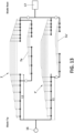
- Figure 13 shows an embodiment having two main spar caps (7,7') and two secondary spar caps (7a,7a') shorter than the main spar caps and parallel to them.
- the distance between the tip end of a secondary beam (7a,7a') to the tip end of the main beam (7,7') is equal or longer than the distance (L1) defined above in relation with Figure 4 .
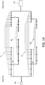
- Figure 14 shows another embodiment also having two main spar caps (7,7') and two secondary spar caps (7a,7a') shorter than the main spar caps and parallel to them.
- the distance between the root end of the secondary beams (7a,7a') to the root end of the main beam (7,7') is shorter than the distance (L1) defined above in relation with Figure 4 .
Landscapes
- Engineering & Computer Science (AREA)
- Life Sciences & Earth Sciences (AREA)
- Sustainable Development (AREA)
- Sustainable Energy (AREA)
- Chemical & Material Sciences (AREA)
- Combustion & Propulsion (AREA)
- Mechanical Engineering (AREA)
- General Engineering & Computer Science (AREA)
- Wind Motors (AREA)
Applications Claiming Priority (1)
| Application Number | Priority Date | Filing Date | Title |
|---|---|---|---|
| EP23382218 | 2023-03-08 |
Publications (2)
| Publication Number | Publication Date |
|---|---|
| EP4428362A1 true EP4428362A1 (de) | 2024-09-11 |
| EP4428362B1 EP4428362B1 (de) | 2025-09-03 |
Family
ID=85556795
Family Applications (1)
| Application Number | Title | Priority Date | Filing Date |
|---|---|---|---|
| EP23168171.9A Active EP4428362B1 (de) | 2023-03-08 | 2023-04-17 | Windturbinenblatt mit integriertem blitzschutzsystem |
Country Status (4)
| Country | Link |
|---|---|
| EP (1) | EP4428362B1 (de) |
| DK (1) | DK4428362T3 (de) |
| ES (1) | ES3052433T3 (de) |
| PT (1) | PT4428362T (de) |
Citations (6)
| Publication number | Priority date | Publication date | Assignee | Title |
|---|---|---|---|---|
| WO2020103991A1 (en) * | 2018-11-20 | 2020-05-28 | Vestas Wind Systems A/S | Equipotential bonding of wind turbine rotor blade |
| WO2021228606A1 (en) | 2020-05-14 | 2021-11-18 | Siemens Gamesa Renewable Energy A/S | Wind turbine blade and wind turbine |
| US20210404443A1 (en) * | 2018-11-20 | 2021-12-30 | Vestas Wind Systems A/S | Equipotential bonding of wind turbine rotor blade |
| EP3943745A1 (de) | 2020-07-22 | 2022-01-26 | Siemens Gamesa Renewable Energy Innovation & Technology S.L. | Blitzschutzsystem für eine pultrudierte kohlenstoffschaufel sowie pultrudierte kohlenstoffschaufel |
| EP3997331A1 (de) * | 2019-07-12 | 2022-05-18 | Vestas Wind Systems A/S | Verbindung für geteiltes windturbinenblatt |
| US11346328B2 (en) * | 2017-08-24 | 2022-05-31 | Vestas Wind Systems A/S | Wind turbine rotor blade lightning receptor arrangement |
-
2023
- 2023-04-17 EP EP23168171.9A patent/EP4428362B1/de active Active
- 2023-04-17 PT PT231681719T patent/PT4428362T/pt unknown
- 2023-04-17 ES ES23168171T patent/ES3052433T3/es active Active
- 2023-04-17 DK DK23168171.9T patent/DK4428362T3/da active
Patent Citations (6)
| Publication number | Priority date | Publication date | Assignee | Title |
|---|---|---|---|---|
| US11346328B2 (en) * | 2017-08-24 | 2022-05-31 | Vestas Wind Systems A/S | Wind turbine rotor blade lightning receptor arrangement |
| WO2020103991A1 (en) * | 2018-11-20 | 2020-05-28 | Vestas Wind Systems A/S | Equipotential bonding of wind turbine rotor blade |
| US20210404443A1 (en) * | 2018-11-20 | 2021-12-30 | Vestas Wind Systems A/S | Equipotential bonding of wind turbine rotor blade |
| EP3997331A1 (de) * | 2019-07-12 | 2022-05-18 | Vestas Wind Systems A/S | Verbindung für geteiltes windturbinenblatt |
| WO2021228606A1 (en) | 2020-05-14 | 2021-11-18 | Siemens Gamesa Renewable Energy A/S | Wind turbine blade and wind turbine |
| EP3943745A1 (de) | 2020-07-22 | 2022-01-26 | Siemens Gamesa Renewable Energy Innovation & Technology S.L. | Blitzschutzsystem für eine pultrudierte kohlenstoffschaufel sowie pultrudierte kohlenstoffschaufel |
Also Published As
| Publication number | Publication date |
|---|---|
| DK4428362T3 (en) | 2025-11-10 |
| PT4428362T (pt) | 2025-11-18 |
| ES3052433T3 (en) | 2026-01-07 |
| EP4428362B1 (de) | 2025-09-03 |
Similar Documents
| Publication | Publication Date | Title |
|---|---|---|
| US10330087B2 (en) | Lightning protection system for wind turbine blades with an effective injection area to carbon fiber laminates and a balanced lightning current and voltage distribution between different conductive paths | |
| CN108700041B (zh) | 风力涡轮机叶片以及电位均衡系统 | |
| US9689377B2 (en) | Wind turbine rotor blade having an electrical heating device and a plurality of lightning conductors | |
| CN103329379B (zh) | 风力涡轮机叶片 | |
| EP3548742B1 (de) | Kohlenstoffschaufel für windkraftgenerator mit mehrfachableitung | |
| KR20130093529A (ko) | 풍력 터빈용 풍력 터빈 블레이드 | |
| DE102016206798A1 (de) | Solarzellenanordnung | |
| CN113969875A (zh) | 用于碳拉挤叶片的雷电防护系统以及碳拉挤叶片 | |
| EP3255274B1 (de) | Blitzschutzsystem für windturbinenschaufeln mit optimierten mitteln zur injektion von blitzströmen in leitende komponenten ihrer schalen | |
| EP2708740B1 (de) | Windenergieanlagenrotorblatt mit einer elektrischen Heizeinrichtung und einem Blitzableiter | |
| US11614077B2 (en) | Wind turbine blade for a wind turbine and method of manufacturing a wind turbine blade | |
| EP4428362A1 (de) | Windturbinenblatt mit integriertem blitzschutzsystem | |
| EP2930358B1 (de) | Windenergieanlagenrotorblatt mit einem Potentialausgleichselement | |
| US12352243B1 (en) | Wind turbine blade integrating a lightning protection system | |
| EP4083416A1 (de) | Windturbinenschaufel und windturbine | |
| CN121408131A (zh) | 集成防雷系统的风力涡轮机叶片 | |
| EP2380177A1 (de) | Gleichstromkabel für hochspannungen | |
| US12529358B2 (en) | Wind turbine blade including two lightning down conductor arrangements and wind turbine | |
| EP4603699A1 (de) | Blitzschutzanordnung für ein rotorblatt | |
| TW202536293A (zh) | 轉子葉片的避雷組件 | |
| JP2022017021A (ja) | 風車ブレードの誘雷装置および風力発電装置 |
Legal Events
| Date | Code | Title | Description |
|---|---|---|---|
| PUAI | Public reference made under article 153(3) epc to a published international application that has entered the european phase |
Free format text: ORIGINAL CODE: 0009012 |
|
| STAA | Information on the status of an ep patent application or granted ep patent |
Free format text: STATUS: THE APPLICATION HAS BEEN PUBLISHED |
|
| AK | Designated contracting states |
Kind code of ref document: A1 Designated state(s): AL AT BE BG CH CY CZ DE DK EE ES FI FR GB GR HR HU IE IS IT LI LT LU LV MC ME MK MT NL NO PL PT RO RS SE SI SK SM TR |
|
| STAA | Information on the status of an ep patent application or granted ep patent |
Free format text: STATUS: REQUEST FOR EXAMINATION WAS MADE |
|
| 17P | Request for examination filed |
Effective date: 20250311 |
|
| RIC1 | Information provided on ipc code assigned before grant |
Ipc: F03D 80/30 20160101ALI20250327BHEP Ipc: F03D 1/06 20060101AFI20250327BHEP |
|
| GRAP | Despatch of communication of intention to grant a patent |
Free format text: ORIGINAL CODE: EPIDOSNIGR1 |
|
| STAA | Information on the status of an ep patent application or granted ep patent |
Free format text: STATUS: GRANT OF PATENT IS INTENDED |
|
| INTG | Intention to grant announced |
Effective date: 20250502 |
|
| GRAS | Grant fee paid |
Free format text: ORIGINAL CODE: EPIDOSNIGR3 |
|
| GRAA | (expected) grant |
Free format text: ORIGINAL CODE: 0009210 |
|
| STAA | Information on the status of an ep patent application or granted ep patent |
Free format text: STATUS: THE PATENT HAS BEEN GRANTED |
|
| AK | Designated contracting states |
Kind code of ref document: B1 Designated state(s): AL AT BE BG CH CY CZ DE DK EE ES FI FR GB GR HR HU IE IS IT LI LT LU LV MC ME MK MT NL NO PL PT RO RS SE SI SK SM TR |
|
| REG | Reference to a national code |
Ref country code: CH Ref legal event code: EP |
|
| REG | Reference to a national code |
Ref country code: DE Ref legal event code: R096 Ref document number: 602023006240 Country of ref document: DE |
|
| REG | Reference to a national code |
Ref country code: IE Ref legal event code: FG4D |
|
| REG | Reference to a national code |
Ref country code: DK Ref legal event code: T3 Effective date: 20251107 |
|
| REG | Reference to a national code |
Ref country code: PT Ref legal event code: SC4A Ref document number: 4428362 Country of ref document: PT Date of ref document: 20251118 Kind code of ref document: T Free format text: AVAILABILITY OF NATIONAL TRANSLATION Effective date: 20251111 |
|
| REG | Reference to a national code |
Ref country code: ES Ref legal event code: FG2A Ref document number: 3052433 Country of ref document: ES Kind code of ref document: T3 Effective date: 20260107 Ref country code: NL Ref legal event code: MP Effective date: 20250903 |
|
| PG25 | Lapsed in a contracting state [announced via postgrant information from national office to epo] |
Ref country code: NO Free format text: LAPSE BECAUSE OF FAILURE TO SUBMIT A TRANSLATION OF THE DESCRIPTION OR TO PAY THE FEE WITHIN THE PRESCRIBED TIME-LIMIT Effective date: 20251203 |
|
| REG | Reference to a national code |
Ref country code: LT Ref legal event code: MG9D |
|
| PG25 | Lapsed in a contracting state [announced via postgrant information from national office to epo] |
Ref country code: FI Free format text: LAPSE BECAUSE OF FAILURE TO SUBMIT A TRANSLATION OF THE DESCRIPTION OR TO PAY THE FEE WITHIN THE PRESCRIBED TIME-LIMIT Effective date: 20250903 |
|
| PG25 | Lapsed in a contracting state [announced via postgrant information from national office to epo] |
Ref country code: HR Free format text: LAPSE BECAUSE OF FAILURE TO SUBMIT A TRANSLATION OF THE DESCRIPTION OR TO PAY THE FEE WITHIN THE PRESCRIBED TIME-LIMIT Effective date: 20250903 |
|
| PG25 | Lapsed in a contracting state [announced via postgrant information from national office to epo] |
Ref country code: GR Free format text: LAPSE BECAUSE OF FAILURE TO SUBMIT A TRANSLATION OF THE DESCRIPTION OR TO PAY THE FEE WITHIN THE PRESCRIBED TIME-LIMIT Effective date: 20251204 |
|
| PG25 | Lapsed in a contracting state [announced via postgrant information from national office to epo] |
Ref country code: SE Free format text: LAPSE BECAUSE OF FAILURE TO SUBMIT A TRANSLATION OF THE DESCRIPTION OR TO PAY THE FEE WITHIN THE PRESCRIBED TIME-LIMIT Effective date: 20250903 |
|
| PG25 | Lapsed in a contracting state [announced via postgrant information from national office to epo] |
Ref country code: LV Free format text: LAPSE BECAUSE OF FAILURE TO SUBMIT A TRANSLATION OF THE DESCRIPTION OR TO PAY THE FEE WITHIN THE PRESCRIBED TIME-LIMIT Effective date: 20250903 |
|
| PG25 | Lapsed in a contracting state [announced via postgrant information from national office to epo] |
Ref country code: BG Free format text: LAPSE BECAUSE OF FAILURE TO SUBMIT A TRANSLATION OF THE DESCRIPTION OR TO PAY THE FEE WITHIN THE PRESCRIBED TIME-LIMIT Effective date: 20250903 Ref country code: PL Free format text: LAPSE BECAUSE OF FAILURE TO SUBMIT A TRANSLATION OF THE DESCRIPTION OR TO PAY THE FEE WITHIN THE PRESCRIBED TIME-LIMIT Effective date: 20250903 |
|
| PG25 | Lapsed in a contracting state [announced via postgrant information from national office to epo] |
Ref country code: RS Free format text: LAPSE BECAUSE OF FAILURE TO SUBMIT A TRANSLATION OF THE DESCRIPTION OR TO PAY THE FEE WITHIN THE PRESCRIBED TIME-LIMIT Effective date: 20251203 |
|
| REG | Reference to a national code |
Ref country code: AT Ref legal event code: MK05 Ref document number: 1833306 Country of ref document: AT Kind code of ref document: T Effective date: 20250903 |
|
| PG25 | Lapsed in a contracting state [announced via postgrant information from national office to epo] |
Ref country code: NL Free format text: LAPSE BECAUSE OF FAILURE TO SUBMIT A TRANSLATION OF THE DESCRIPTION OR TO PAY THE FEE WITHIN THE PRESCRIBED TIME-LIMIT Effective date: 20250903 |
|
| PG25 | Lapsed in a contracting state [announced via postgrant information from national office to epo] |
Ref country code: SM Free format text: LAPSE BECAUSE OF FAILURE TO SUBMIT A TRANSLATION OF THE DESCRIPTION OR TO PAY THE FEE WITHIN THE PRESCRIBED TIME-LIMIT Effective date: 20250903 |
|
| PG25 | Lapsed in a contracting state [announced via postgrant information from national office to epo] |
Ref country code: AT Free format text: LAPSE BECAUSE OF FAILURE TO SUBMIT A TRANSLATION OF THE DESCRIPTION OR TO PAY THE FEE WITHIN THE PRESCRIBED TIME-LIMIT Effective date: 20250903 |
|
| PG25 | Lapsed in a contracting state [announced via postgrant information from national office to epo] |
Ref country code: IT Free format text: LAPSE BECAUSE OF FAILURE TO SUBMIT A TRANSLATION OF THE DESCRIPTION OR TO PAY THE FEE WITHIN THE PRESCRIBED TIME-LIMIT Effective date: 20250903 |
|
| PG25 | Lapsed in a contracting state [announced via postgrant information from national office to epo] |
Ref country code: IS Free format text: LAPSE BECAUSE OF FAILURE TO SUBMIT A TRANSLATION OF THE DESCRIPTION OR TO PAY THE FEE WITHIN THE PRESCRIBED TIME-LIMIT Effective date: 20260103 |
|
| PG25 | Lapsed in a contracting state [announced via postgrant information from national office to epo] |
Ref country code: CZ Free format text: LAPSE BECAUSE OF FAILURE TO SUBMIT A TRANSLATION OF THE DESCRIPTION OR TO PAY THE FEE WITHIN THE PRESCRIBED TIME-LIMIT Effective date: 20250903 |
|
| PGFP | Annual fee paid to national office [announced via postgrant information from national office to epo] |
Ref country code: PT Payment date: 20260327 Year of fee payment: 4 |
|
| PG25 | Lapsed in a contracting state [announced via postgrant information from national office to epo] |
Ref country code: EE Free format text: LAPSE BECAUSE OF FAILURE TO SUBMIT A TRANSLATION OF THE DESCRIPTION OR TO PAY THE FEE WITHIN THE PRESCRIBED TIME-LIMIT Effective date: 20250903 Ref country code: SK Free format text: LAPSE BECAUSE OF FAILURE TO SUBMIT A TRANSLATION OF THE DESCRIPTION OR TO PAY THE FEE WITHIN THE PRESCRIBED TIME-LIMIT Effective date: 20250903 |