EP4428264A2 - Modifizierung von werkzeugen zur chemischen dampfinfiltration zur optimierung der infiltration in keramikmatrixverbundstoffen - Google Patents
Modifizierung von werkzeugen zur chemischen dampfinfiltration zur optimierung der infiltration in keramikmatrixverbundstoffen Download PDFInfo
- Publication number
- EP4428264A2 EP4428264A2 EP24161857.8A EP24161857A EP4428264A2 EP 4428264 A2 EP4428264 A2 EP 4428264A2 EP 24161857 A EP24161857 A EP 24161857A EP 4428264 A2 EP4428264 A2 EP 4428264A2
- Authority
- EP
- European Patent Office
- Prior art keywords
- hole
- holes
- outlet
- inlet
- tooling fixture
- Prior art date
- Legal status (The legal status is an assumption and is not a legal conclusion. Google has not performed a legal analysis and makes no representation as to the accuracy of the status listed.)
- Pending
Links
Images
Classifications
-
- C—CHEMISTRY; METALLURGY
- C23—COATING METALLIC MATERIAL; COATING MATERIAL WITH METALLIC MATERIAL; CHEMICAL SURFACE TREATMENT; DIFFUSION TREATMENT OF METALLIC MATERIAL; COATING BY VACUUM EVAPORATION, BY SPUTTERING, BY ION IMPLANTATION OR BY CHEMICAL VAPOUR DEPOSITION, IN GENERAL; INHIBITING CORROSION OF METALLIC MATERIAL OR INCRUSTATION IN GENERAL
- C23C—COATING METALLIC MATERIAL; COATING MATERIAL WITH METALLIC MATERIAL; SURFACE TREATMENT OF METALLIC MATERIAL BY DIFFUSION INTO THE SURFACE, BY CHEMICAL CONVERSION OR SUBSTITUTION; COATING BY VACUUM EVAPORATION, BY SPUTTERING, BY ION IMPLANTATION OR BY CHEMICAL VAPOUR DEPOSITION, IN GENERAL
- C23C16/00—Chemical coating by decomposition of gaseous compounds, without leaving reaction products of surface material in the coating, i.e. chemical vapour deposition [CVD] processes
- C23C16/04—Coating on selected surface areas, e.g. using masks
- C23C16/045—Coating cavities or hollow spaces, e.g. interior of tubes; Infiltration of porous substrates
-
- C—CHEMISTRY; METALLURGY
- C23—COATING METALLIC MATERIAL; COATING MATERIAL WITH METALLIC MATERIAL; CHEMICAL SURFACE TREATMENT; DIFFUSION TREATMENT OF METALLIC MATERIAL; COATING BY VACUUM EVAPORATION, BY SPUTTERING, BY ION IMPLANTATION OR BY CHEMICAL VAPOUR DEPOSITION, IN GENERAL; INHIBITING CORROSION OF METALLIC MATERIAL OR INCRUSTATION IN GENERAL
- C23C—COATING METALLIC MATERIAL; COATING MATERIAL WITH METALLIC MATERIAL; SURFACE TREATMENT OF METALLIC MATERIAL BY DIFFUSION INTO THE SURFACE, BY CHEMICAL CONVERSION OR SUBSTITUTION; COATING BY VACUUM EVAPORATION, BY SPUTTERING, BY ION IMPLANTATION OR BY CHEMICAL VAPOUR DEPOSITION, IN GENERAL
- C23C16/00—Chemical coating by decomposition of gaseous compounds, without leaving reaction products of surface material in the coating, i.e. chemical vapour deposition [CVD] processes
- C23C16/44—Chemical coating by decomposition of gaseous compounds, without leaving reaction products of surface material in the coating, i.e. chemical vapour deposition [CVD] processes characterised by the method of coating
- C23C16/455—Chemical coating by decomposition of gaseous compounds, without leaving reaction products of surface material in the coating, i.e. chemical vapour deposition [CVD] processes characterised by the method of coating characterised by the method used for introducing gases into reaction chamber or for modifying gas flows in reaction chamber
- C23C16/45563—Gas nozzles
- C23C16/45565—Shower nozzles
Definitions
- the present invention relates to chemical vapor infiltration (CVI), and more particularly to improved tooling for CVI.
- Ceramic matrix composite (CMC) parts are widely fabricated by applying an interface coating (IFC) to preforms made from woven fabrics or oriented/braided fiber tows.
- IFC interface coating
- perforated tooling can be used to hold the preforms during the initial densification cycle(s). Holes in the tooling allow vaporous precursors to infiltrate into the preform for the deposition of a ceramic matrix.
- Tooling for simple preform shapes can be designed with uniform hole dimensions. When used with complexly-shaped preforms such as turbine airfoils, vaporous precursors may not sufficiently infiltrate the preform at certain locations through such holes. The result can be undesirable variation in deposition rate and effective IFC thickness, which can drive differences in mechanical behavior and durability of the CMC part. Thus, a need exists for improved tooling.
- a tooling fixture suitable for use in infiltrating a fibrous preform with a reactant gas includes an outer surface and opposing inner surface defining a thickness therebetween, and a plurality of holes extending through the thickness.
- Each hole of the plurality of holes includes an inlet at the outer surface, the inlet configured to receive a flow of the reactant gas, an outlet at the inner surface, a transition point between the inlet and the outlet, and an angled segment extending from the transition point to the outlet.
- Each hole of the plurality of holes has a first diameter at the inlet and a second diameter at the outlet, and the second diameter is greater than the first diameter.
- a tooling fixture suitable for use in infiltrating a fibrous preform with a reactant gas includes an outer surface and opposing inner surface defining a thickness therebetween, and a plurality of holes extending through the thickness.
- Each hole of the plurality of holes includes an inlet at the outer surface, the inlet configured to receive a flow of the reactant gas, an outlet at the inner surface, a transition point between the inlet and the outlet, and at least one branching hole extending away from the hole between the transition point and the outer surface.
- a tooling fixture suitable for use in infiltrating a fibrous preform with a reactant gas includes an outer surface and opposing inner surface defining a thickness therebetween, and a plurality of holes extending through the thickness.
- Each hole of the plurality of holes includes an inlet at the outer surface, and an outlet at the inner surface.
- the tooling fixture further includes a first hole concentration at the outer surface, the first hole concentration being defined by an inlet diameter of each hole of the plurality of holes, and a second hole concentration at the inner surface, the second hole concentration defined by an outlet diameter of each hole of the plurality of holes. The second hole concentration is greater than the first hole concentration.
- This disclosure presents various expanding-diameter infiltration holes for a tooling fixture.
- the conical, directional, and branching configurations discussed herein allow for an increase in hole concentration on the inner, preform-facing surface of the tooling fixture to facilitate a more even and/or tailored deposition of reactant gases on the enclosed preform.
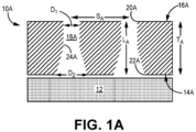
- FIGS. 1A , 1B , and 1C are simplified, enlarged cross-sectional illustrations of alternative infiltration holes 18A, 18B, and 18C, respectively, for a tooling fixture.
- FIGS. 1A , 1B , and 1C are discussed together.
- FIG. 1A illustrates a portion/side of tooling fixture 10A and enclosed preform 12.
- Tooling fixture 10A can, in an exemplary embodiment, be formed from graphite.
- tooling fixture 10A can be entirely or partially formed from refractory metal alloys, carbon-carbon composites, and/or a ceramic (e.g., silicon carbide, aluminum oxide, boron nitride, etc.).
- Preform 12 can be formed from tows of silicon carbide (SiC) or other ceramic fibers arranged in one of various two or three-dimensional woven architectures such as plain, harness (e.g., 3, 5, 8, etc.), twill, braid, or non-symmetric, to name a few non-limiting examples.
- preform 12 can be formed from non-woven (e.g., chopped, felted, etc.) fibers.
- Tooling fixture 10A can at least partially surround preform 12 to help maintain the shape of preform 12 during CVI.
- Tooling fixture 10A and preform 12 can each include straight and/or curved segments depending on the geometry desired in the final CMC part.
- each hole 18A has a uniform first diameter D1 between inlet 20A and transition point 24A, and a second diameter D2 measured at outlet 22A.
- the diameter linearly increases between transition point 24A and outlet 22A such that D1 ⁇ D2, and D2 is also the maximum diameter along length L A of hole 18A.
- D1 can be 0.125 in (3.175 mm) and D2 can range from 0.131 in to 0.25 in (3.33 mm to 6.35 mm).
- D2 can generally be 1.05 times to 2.0 times greater than D1.
- Hole diameters e.g., D1 and D2
- D1 and D2 can be optimized to improve infiltration while balancing the effects of "pillowing” (the elastic expansion of preform 12 material into a hole).
- Holes 18A can be referred to as "conical outlet holes.” Each hole 18A can be spaced apart from an adjacent hole 18A a distance Sa, as measured from hole midpoint to midpoint.
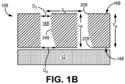
- FIG. 1B illustrates alternative tooling fixture 10B supporting preform 12.
- Tooling fixture 10B is substantially similar to tooling fixture 10A having a thickness T B defined by inner and outer surfaces 14B and 16B, respectively.
- Each hole 18B similarly has a cylindrical three-dimensional geometry (and rectangular cross-sectional area), beginning at inlet 20B and extending inward toward outlet 22B, but transitions to a partially frustoconical three-dimensional geometry (and partial trapezoidal area) at transition point 24B.
- each hole 18B is asymmetrical between transition point 24B and outlet 22B, with one straight wall segment and one angled wall segment. Holes 18B can be referred to as "directional outlet holes.”
- Each hole 18B has a uniform first diameter D3 between inlet 22B and transition point 24B, and a second diameter D4 at outlet 22A. The diameter linearly increases over a portion of hole 18B between transition point 24B and outlet 22B such that D3 ⁇ D4, and D4 is also the maximum diameter along length L B of hole 18B.
- D3 can be 0.125 in (3.175 mm) and D4 can range from 0.131 in to 0.25 in (3.33 mm to 6.35 mm).
- Each hole 18B can be spaced apart from an adjacent hole 18B a distance S B , as measured from hole midpoint to midpoint.
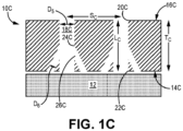
- FIG. 1C illustrates alternative tooling fixture 10C supporting preform 12.
- Tooling fixture 10Cs is substantially similar to tooling fixtures 10A and 10B having a thickness T C defined by inner and outer surfaces 14C and 16C, respectively.
- each hole 18C has a cylindrical three-dimensional geometry between inlet 20C and outlet 22C with a uniform first diameter D5. In one embodiment, D5 can be 0.125 in (3.175 mm).
- each hole 18C includes one or more branching holes 26C branching off a respective hole 18C at transition point 24C.
- Branching holes 26C extend from transition point 24C to inner surface 14C to fluidly connect a respective hole 18C to the space between inner surface 14C and preform 12.
- Holes 18C can include additional branching holes 26C, for example with an additional transition point 24C closer to inlet 20C.
- Each hole 18C can be spaced apart from an adjacent hole 18C a distance Sc, as measured from hole midpoint to midpoint.
- Holes 18A, 18B, and 18C allow for reactant gases to be spread across a larger area of preform 12, by widening (i.e., increasing hole diameter) and/or otherwise increasing the total hole (i.e., open area) concentration on the inner surface of the respective tooling fixture relative to the outer surface. This can allow for a more uniform IFC deposition on preform 12 by more evenly spreading the reactant gas using the modified outlet geometries of holes 18A, 18B, and 18C, compared to cylindrical holes alone. Holes 18B can be used to supply a more targeted, directional flow of reactant gas on preform 12 based on the direction of the angled wall segment. Similarly, an alternative embodiment of hole 18C can include a single branching hole 26C to achieve a directional flow.
- holes 18A, 18B, and/or 18C can be included in a single tooling fixture and/or combined with cylindrical holes depending on, for example, preform geometry, thickness, etc.
- Holes 18A, 18B, and 18C can be formed using a laser or mechanical drilling technique, including countersinking for holes 18A.
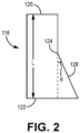
- FIG. 2 is a simplified cross-sectional illustration of one embodiment of hole 118, shown in isolation from a tooling fixture.
- Hole 118 can, for example, be a directional cooling hole (i.e., 18B), but can also be applied to hole 18A.
- Hole 118 includes inlet 120, outlet 122, and length L measured between inlet 120 and outlet 122.
- Transition point 124 is positioned somewhere along length L. In an exemplary embodiment, transition point 124 can be positioned at about 75% length L, with respect to a starting point at inlet 120, such that transition point 124 is relatively closer to outlet 122.
- Angled segment (i.e., hypotenuse) 128 extends from transition point 124 and extends to outlet 122.
- Angled segment 128 creates diffusion angle ⁇ at transition point 124 which can range from 0° to 30°, more narrowly from 5° to 20°, or even more narrowly from 7° to 10°. Such ranges allow for a desirable increase in hole diameter at outlet 122 while minimizing the separation of reactant gas flow from the internal surface of hole 118.
- Holes 18A and 18B can include substantially similar transition points and diffusion angles.
- branching holes 26C may be disposed relative to a respective hole 18C at an angle falling within the ranges listed above, but the angle can be greater than 30° in some embodiments.
- the disclosed tooling fixtures can be used to form CMC components for aerospace, maritime, or industrial equipment, to name a few, non-limiting examples.
- a tooling fixture suitable for use in infiltrating a fibrous preform with a reactant gas includes an outer surface and opposing inner surface defining a thickness therebetween, and a plurality of holes extending through the thickness.
- Each hole of the plurality of holes includes an inlet at the outer surface, the inlet configured to receive a flow of the reactant gas, an outlet at the inner surface, a transition point between the inlet and the outlet, and an angled segment extending from the transition point to the outlet.
- Each hole of the plurality of holes has a first diameter at the inlet and a second diameter at the outlet, and the second diameter is greater than the first diameter.
- the tooling fixture of the preceding paragraph can optionally include, additionally and/or alternatively, any one or more of the following features, configurations and/or additional components:
- the first diameter can be 0.125 in (3.175 mm).
- each hole of the plurality of holes can be cylindrical between the inlet and the transition point.
- each hole of the plurality of holes can be at least partially frustoconical between the transition point and the outlet.
- the angled segment can define a diffusion angle at the transition point, and the diffusion angle can range from 5° to 20°.
- the tooling fixture can be formed from at least one of graphite, a refractory metal alloy, a carbon-carbon composite, and a ceramic material.
- a tooling fixture suitable for use in infiltrating a fibrous preform with a reactant gas includes an outer surface and opposing inner surface defining a thickness therebetween, and a plurality of holes extending through the thickness.
- Each hole of the plurality of holes includes an inlet at the outer surface, the inlet configured to receive a flow of the reactant gas, an outlet at the inner surface, a transition point between the inlet and the outlet, and at least one branching hole extending away from the hole between the transition point and the outer surface.
- each hole of the plurality of holes can be cylindrical between the inlet and the outlet with a uniform first diameter.
- the at least one branching hole can be cylindrical with a uniform second diameter.
- the first diameter can be greater than the second diameter.
- the at least one branching hole can include a plurality of branching holes.
- the tooling fixture can be formed from at least one of graphite, a refractory metal alloy, a carbon-carbon composite, and a ceramic material.
- a tooling fixture suitable for use in infiltrating a fibrous preform with a reactant gas includes an outer surface and opposing inner surface defining a thickness therebetween, and a plurality of holes extending through the thickness.
- Each hole of the plurality of holes includes an inlet at the outer surface, and an outlet at the inner surface.
- the tooling fixture further includes a first hole concentration at the outer surface, the first hole concentration being defined by an inlet diameter of each hole of the plurality of holes, and a second hole concentration at the inner surface, the second hole concentration defined by an outlet diameter of each hole of the plurality of holes. The second hole concentration is greater than the first hole concentration.
- each hole of the plurality of holes can further include a transition point between the inlet and the outlet, and an angled segment extending from the transition point to the outlet.
- each hole of the plurality of holes can be cylindrical between the inlet and the transition point.
- each hole of the plurality of holes can be at least partially frustoconical between the transition point and the outlet.
- each hole of the plurality of holes can be cylindrical between the inlet and the outlet.
- each hole of the plurality of holes can include at least one branching hole extending away from the hole between the transition point and the outer surface, and the at least one branching hole can define the angled segment.
- the angled segment can define a diffusion angle at the transition point, the diffusion angle can range from 5° to 20°.
- the tooling fixture can be formed from at least one of graphite, a refractory metal alloy, a carbon-carbon composite, and a ceramic material.
Landscapes
- Chemical & Material Sciences (AREA)
- General Chemical & Material Sciences (AREA)
- Chemical Kinetics & Catalysis (AREA)
- Engineering & Computer Science (AREA)
- Materials Engineering (AREA)
- Mechanical Engineering (AREA)
- Metallurgy (AREA)
- Organic Chemistry (AREA)
- Chemical Vapour Deposition (AREA)
Applications Claiming Priority (1)
| Application Number | Priority Date | Filing Date | Title |
|---|---|---|---|
| US18/118,450 US12503759B2 (en) | 2023-03-07 | 2023-03-07 | Chemical vapor infiltration tooling hole modification for optimizing infiltration in ceramic matrix composites |
Publications (2)
| Publication Number | Publication Date |
|---|---|
| EP4428264A2 true EP4428264A2 (de) | 2024-09-11 |
| EP4428264A3 EP4428264A3 (de) | 2025-01-22 |
Family
ID=90362810
Family Applications (1)
| Application Number | Title | Priority Date | Filing Date |
|---|---|---|---|
| EP24161857.8A Pending EP4428264A3 (de) | 2023-03-07 | 2024-03-06 | Modifizierung von werkzeugen zur chemischen dampfinfiltration zur optimierung der infiltration in keramikmatrixverbundstoffen |
Country Status (2)
| Country | Link |
|---|---|
| US (1) | US12503759B2 (de) |
| EP (1) | EP4428264A3 (de) |
Family Cites Families (24)
| Publication number | Priority date | Publication date | Assignee | Title |
|---|---|---|---|---|
| US3991248A (en) | 1972-03-28 | 1976-11-09 | Ducommun Incorporated | Fiber reinforced composite product |
| JPS58176196A (ja) | 1982-04-06 | 1983-10-15 | Matsushita Electric Ind Co Ltd | 化合物結晶成長装置 |
| CA1272661A (en) | 1985-05-11 | 1990-08-14 | Yuji Chiba | Reaction apparatus |
| FR2670507B1 (fr) | 1990-12-18 | 1993-12-31 | Propulsion Ste Europeenne | Procede d'infiltration chimique en phase vapeur. |
| JP4849705B2 (ja) * | 2000-03-24 | 2012-01-11 | 東京エレクトロン株式会社 | プラズマ処理装置、プラズマ生成導入部材及び誘電体 |
| KR100766132B1 (ko) | 2005-08-31 | 2007-10-12 | 코바렌트 마테리얼 가부시키가이샤 | 가스 분산판 및 그 제조방법 |
| US20080302303A1 (en) * | 2007-06-07 | 2008-12-11 | Applied Materials, Inc. | Methods and apparatus for depositing a uniform silicon film with flow gradient designs |
| JP5093165B2 (ja) | 2009-03-17 | 2012-12-05 | 株式会社Ihi | 構造物の製造方法及び構造物 |
| US20120097330A1 (en) | 2010-10-20 | 2012-04-26 | Applied Materials, Inc. | Dual delivery chamber design |
| US8845806B2 (en) | 2010-10-22 | 2014-09-30 | Asm Japan K.K. | Shower plate having different aperture dimensions and/or distributions |
| US9484190B2 (en) | 2014-01-25 | 2016-11-01 | Yuri Glukhoy | Showerhead-cooler system of a semiconductor-processing chamber for semiconductor wafers of large area |
| WO2017074700A1 (en) | 2015-10-26 | 2017-05-04 | Applied Materials, Inc. | High productivity pecvd tool for wafer processing of semiconductor manufacturing |
| FR3059679B1 (fr) | 2016-12-07 | 2021-03-12 | Safran Ceram | Outillage de conformation et installation pour l'infiltration chimique en phase gazeuse de preformes fibreuses |
| US20180340257A1 (en) | 2017-05-25 | 2018-11-29 | Applied Materials, Inc. | Diffuser for uniformity improvement in display pecvd applications |
| CN107266099B (zh) | 2017-06-16 | 2023-07-18 | 中国人民解放军第五七一九工厂 | 一种航空发动机陶瓷基复合材料涡轮导向器叶片近净成型用夹具 |
| KR102572740B1 (ko) | 2018-06-08 | 2023-08-29 | 어플라이드 머티어리얼스, 인코포레이티드 | 플랫 패널 프로세스 장비를 위한 온도 제어식 가스 확산기 |
| US11820716B2 (en) | 2018-10-18 | 2023-11-21 | Rolls Royce North American Technologies Inc. | Method of fabricating cooling features on a ceramic matrix composite (CMC) component |
| US10906842B2 (en) | 2018-10-18 | 2021-02-02 | Rolls-Royce High Temperature Composites Inc. | Method of processing a ceramic matrix composite (CMC) component |
| US11046620B2 (en) | 2018-10-18 | 2021-06-29 | Rolls-Royce Corporation | Method of processing a ceramic matrix composite (CMC) component |
| US11332827B2 (en) | 2019-03-27 | 2022-05-17 | Applied Materials, Inc. | Gas distribution plate with high aspect ratio holes and a high hole density |
| US11472747B2 (en) | 2019-10-08 | 2022-10-18 | Rolls-Royce High Temperature Composites Inc. | Assembly for chemical vapor infiltration of a fiber preform and method of infiltrating a fiber preform |
| DE102019134116A1 (de) | 2019-12-12 | 2021-06-17 | AP&S International GmbH | Vorrichtung zum stromlosen Metallisieren einer Zieloberfläche wenigstens eines Werkstücks sowie Verfahren und Diffusorplatte hierzu |
| US20220195606A1 (en) | 2020-12-23 | 2022-06-23 | Raytheon Technologies Corporation | Method for metal vapor infiltration of cmc parts and articles containing the same |
| CN115181959B (zh) | 2022-06-21 | 2023-09-01 | 西安鑫垚陶瓷复合材料有限公司 | 大型薄壁陶瓷基复合材料件加工沉积工装及加工方法、使用方法 |
-
2023
- 2023-03-07 US US18/118,450 patent/US12503759B2/en active Active
-
2024
- 2024-03-06 EP EP24161857.8A patent/EP4428264A3/de active Pending
Also Published As
| Publication number | Publication date |
|---|---|
| EP4428264A3 (de) | 2025-01-22 |
| US20240301547A1 (en) | 2024-09-12 |
| US12503759B2 (en) | 2025-12-23 |
Similar Documents
| Publication | Publication Date | Title |
|---|---|---|
| US9453421B2 (en) | Apparatus having engineered surface feature and method to reduce wear and friction between CMC-to-metal attachment and interface | |
| JP6689290B2 (ja) | 軸方向保持具を有するタービンリングアセンブリ | |
| JP5646517B2 (ja) | タービンリング組立体 | |
| US9726025B2 (en) | Ceramic matrix composite | |
| US10294802B2 (en) | Turbine engine components with chemical vapor infiltrated isolation layers | |
| US20060140771A1 (en) | Ceramic composite with integrated compliance/wear layer | |
| EP3124750B1 (de) | Leitschaufel aus einem verbundstoff auf keramikbasis und zugehöriges produktionsverfahren | |
| CN101627183A (zh) | 用于气体涡轮机的涡轮机环组件 | |
| EP4428264A2 (de) | Modifizierung von werkzeugen zur chemischen dampfinfiltration zur optimierung der infiltration in keramikmatrixverbundstoffen | |
| EP4461845A1 (de) | Werkzeug zur chemischen dampfinfiltration zur optimierung der infiltration in keramikmatrixverbundstoffen | |
| JP6096663B2 (ja) | 高温アニール用の複合材料ローラ | |
| EP3760604B1 (de) | Verfahren zur bildung von kühlkanälen in einem keramischen matrixverbundbauteil | |
| US12392037B2 (en) | Floating tooling assembly for chemical vapor infiltration | |
| US20240110280A1 (en) | Minimization of chemical vapor infiltration tooling hole length through counterbores | |
| EP4442856A2 (de) | Werkzeug zur chemischen dampfinfiltration zur optimierung der infiltration in keramikmatrixverbundstoffen | |
| US11993548B2 (en) | Minimization of chemical vapor infiltration tooling hole length through windows | |
| EP4345188A1 (de) | Werkzeug aus keramikmatrixverbundstoff für chemisches dampfinfiltrationsverfahren | |
| US20240376017A1 (en) | Prefabricated noodle | |
| US20250128466A1 (en) | Z-channeling into a preform via needle perforation in a stand-alone tool |
Legal Events
| Date | Code | Title | Description |
|---|---|---|---|
| PUAI | Public reference made under article 153(3) epc to a published international application that has entered the european phase |
Free format text: ORIGINAL CODE: 0009012 |
|
| STAA | Information on the status of an ep patent application or granted ep patent |
Free format text: STATUS: THE APPLICATION HAS BEEN PUBLISHED |
|
| AK | Designated contracting states |
Kind code of ref document: A2 Designated state(s): AL AT BE BG CH CY CZ DE DK EE ES FI FR GB GR HR HU IE IS IT LI LT LU LV MC ME MK MT NL NO PL PT RO RS SE SI SK SM TR |
|
| PUAL | Search report despatched |
Free format text: ORIGINAL CODE: 0009013 |
|
| AK | Designated contracting states |
Kind code of ref document: A3 Designated state(s): AL AT BE BG CH CY CZ DE DK EE ES FI FR GB GR HR HU IE IS IT LI LT LU LV MC ME MK MT NL NO PL PT RO RS SE SI SK SM TR |
|
| RIC1 | Information provided on ipc code assigned before grant |
Ipc: C23C 16/455 20060101ALI20241216BHEP Ipc: C23C 16/04 20060101AFI20241216BHEP |
|
| STAA | Information on the status of an ep patent application or granted ep patent |
Free format text: STATUS: REQUEST FOR EXAMINATION WAS MADE |
|
| 17P | Request for examination filed |
Effective date: 20250717 |