EP4428067A1 - Transport apparatus for transferring battery and control method therefor - Google Patents
Transport apparatus for transferring battery and control method therefor Download PDFInfo
- Publication number
- EP4428067A1 EP4428067A1 EP22890298.7A EP22890298A EP4428067A1 EP 4428067 A1 EP4428067 A1 EP 4428067A1 EP 22890298 A EP22890298 A EP 22890298A EP 4428067 A1 EP4428067 A1 EP 4428067A1
- Authority
- EP
- European Patent Office
- Prior art keywords
- tray
- shock
- movement
- amount
- controller
- Prior art date
- Legal status (The legal status is an assumption and is not a legal conclusion. Google has not performed a legal analysis and makes no representation as to the accuracy of the status listed.)
- Pending
Links
Images


Classifications
-
- B—PERFORMING OPERATIONS; TRANSPORTING
- B65—CONVEYING; PACKING; STORING; HANDLING THIN OR FILAMENTARY MATERIAL
- B65G—TRANSPORT OR STORAGE DEVICES, e.g. CONVEYORS FOR LOADING OR TIPPING, SHOP CONVEYOR SYSTEMS OR PNEUMATIC TUBE CONVEYORS
- B65G43/00—Control devices, e.g. for safety, warning or fault-correcting
- B65G43/08—Control devices operated by article or material being fed, conveyed or discharged
-
- H—ELECTRICITY
- H01—ELECTRIC ELEMENTS
- H01M—PROCESSES OR MEANS, e.g. BATTERIES, FOR THE DIRECT CONVERSION OF CHEMICAL ENERGY INTO ELECTRICAL ENERGY
- H01M10/00—Secondary cells; Manufacture thereof
- H01M10/42—Methods or arrangements for servicing or maintenance of secondary cells or secondary half-cells
- H01M10/4207—Methods or arrangements for servicing or maintenance of secondary cells or secondary half-cells for several batteries or cells simultaneously or sequentially
-
- B—PERFORMING OPERATIONS; TRANSPORTING
- B65—CONVEYING; PACKING; STORING; HANDLING THIN OR FILAMENTARY MATERIAL
- B65G—TRANSPORT OR STORAGE DEVICES, e.g. CONVEYORS FOR LOADING OR TIPPING, SHOP CONVEYOR SYSTEMS OR PNEUMATIC TUBE CONVEYORS
- B65G2201/00—Indexing codes relating to handling devices, e.g. conveyors, characterised by the type of product or load being conveyed or handled
- B65G2201/02—Articles
-
- B—PERFORMING OPERATIONS; TRANSPORTING
- B65—CONVEYING; PACKING; STORING; HANDLING THIN OR FILAMENTARY MATERIAL
- B65G—TRANSPORT OR STORAGE DEVICES, e.g. CONVEYORS FOR LOADING OR TIPPING, SHOP CONVEYOR SYSTEMS OR PNEUMATIC TUBE CONVEYORS
- B65G2201/00—Indexing codes relating to handling devices, e.g. conveyors, characterised by the type of product or load being conveyed or handled
- B65G2201/02—Articles
- B65G2201/0235—Containers
- B65G2201/0258—Trays, totes or bins
-
- B—PERFORMING OPERATIONS; TRANSPORTING
- B65—CONVEYING; PACKING; STORING; HANDLING THIN OR FILAMENTARY MATERIAL
- B65G—TRANSPORT OR STORAGE DEVICES, e.g. CONVEYORS FOR LOADING OR TIPPING, SHOP CONVEYOR SYSTEMS OR PNEUMATIC TUBE CONVEYORS
- B65G2203/00—Indexing code relating to control or detection of the articles or the load carriers during conveying
- B65G2203/02—Control or detection
- B65G2203/0208—Control or detection relating to the transported articles
-
- B—PERFORMING OPERATIONS; TRANSPORTING
- B65—CONVEYING; PACKING; STORING; HANDLING THIN OR FILAMENTARY MATERIAL
- B65G—TRANSPORT OR STORAGE DEVICES, e.g. CONVEYORS FOR LOADING OR TIPPING, SHOP CONVEYOR SYSTEMS OR PNEUMATIC TUBE CONVEYORS
- B65G2203/00—Indexing code relating to control or detection of the articles or the load carriers during conveying
- B65G2203/02—Control or detection
- B65G2203/0208—Control or detection relating to the transported articles
- B65G2203/0216—Codes or marks on the article
-
- B—PERFORMING OPERATIONS; TRANSPORTING
- B65—CONVEYING; PACKING; STORING; HANDLING THIN OR FILAMENTARY MATERIAL
- B65G—TRANSPORT OR STORAGE DEVICES, e.g. CONVEYORS FOR LOADING OR TIPPING, SHOP CONVEYOR SYSTEMS OR PNEUMATIC TUBE CONVEYORS
- B65G2203/00—Indexing code relating to control or detection of the articles or the load carriers during conveying
- B65G2203/04—Detection means
- B65G2203/042—Sensors
- B65G2203/046—RFID
-
- B—PERFORMING OPERATIONS; TRANSPORTING
- B65—CONVEYING; PACKING; STORING; HANDLING THIN OR FILAMENTARY MATERIAL
- B65G—TRANSPORT OR STORAGE DEVICES, e.g. CONVEYORS FOR LOADING OR TIPPING, SHOP CONVEYOR SYSTEMS OR PNEUMATIC TUBE CONVEYORS
- B65G2207/00—Indexing codes relating to constructional details, configuration and additional features of a handling device, e.g. Conveyors
- B65G2207/40—Safety features of loads, equipment or persons
-
- H—ELECTRICITY
- H01—ELECTRIC ELEMENTS
- H01M—PROCESSES OR MEANS, e.g. BATTERIES, FOR THE DIRECT CONVERSION OF CHEMICAL ENERGY INTO ELECTRICAL ENERGY
- H01M10/00—Secondary cells; Manufacture thereof
- H01M10/04—Construction or manufacture in general
Definitions
- the present disclosure relates to a transport device for moving batteries and a control method thereof, and in particular, a transport device for moving batteries and a control method thereof that ensure a reduction in the amount of shock transferred to a tray conveying batteries.
- batteries convert chemical energy to electric energy.
- Two or more cells connect, and current flows in the same direction, to form a battery.
- Batteries are produced through a variety of processes, and move for each process in the state where the batteries are contained in a tray.
- the tray containing the batteries moves at a constant speed in a product line where each process proceeds.
- the transport path of the tray on which the batteries are stacked is not always gentle and smooth.
- the tray moving at a constant speed is not affected by a shock in one area but is affected in another area. A shock transferred to the tray during transportation can damage the batteries stacked on the tray.
- the speed of the tray can decrease in advance, such that the shock affecting the tray can lessen.
- the tray cannot help being affected by the shock.
- the obj ective of the present disclosure is to provide a transport device for moving batteries and a control method thereof that can ensure a reduction in the amount of shock transferred to a tray conveying batteries.
- the obj ective of the present disclosure is to provide a transport device for moving batteries and a control method thereof that can adjust the speed of movement of a tray in the case where the tray moves to a point where a large amount of shock is generated.
- the objective of the present disclosure is to provide a transport device for moving batteries and a control method thereof that can adjust the speed of movement of a tray in the case where the tray moves to the point where a very small amount of shock is generated, or the tray moves in the area where no shock is generated.
- a transport device for moving batteries and a control method thereof, according to the present disclosure can adjust the speed of movement of a tray, to reduce the amount of shock transferred to a tray conveying batteries.
- a path of movement of a tray is divided into a plurality of areas, and in the section where a large amount of shock is transferred to the tray, the speed of movement of the tray decreases, to reduce damage to batteries in the tray.
- the speed of movement of the tray increases, to speed up the conveyance of batteries.
- a transport device for moving batteries in one embodiment comprises a tray which conveys batteries while moving along a conveyor belt, a shock sensor that is disposed at the tray, and senses an amount of shock transferred to the tray, one or more recognized members that are installed along a path of the tray, a reader that is disposed at the tray, and recognizes the one or more recognized members, and a controller that receives values measured by the shock sensor and receive recognized member information from the reader and stores the values in a server, determines a movement area from among the plurality of movement areas in which a predetermined amount of shock or greater is transferred to the tray based on the received values and recognized member information, and decreases a speed of movement of the tray at the determined movement area.
- the one or more recognized members are a radio-frequency identification (RFID) tags, and the reader uses a sensor recognizing RFID tags.
- RFID radio-frequency identification
- the one or more recognized members may be a plurality of recognized members, whereby each recognized member is installed at a respective movement area of the plurality of movement areas.
- the controller determines an amount of shock transferred to the tray in the server, in relation to each of the movement areas.
- the controller calculates a shock area in which a predetermined amount or greater of shock is transferred to the tray, based on information stored in the server, and in the shock area, deceases the speed of movement of the tray.
- a control method of a transport device for moving batteries in one embodiment comprises dividing, by a controller, a path of a tray into a plurality of movement areas, recognizing, by a reader disposed at the tray, a recognized member installed areas along the path of the tray, sensing, by a shock sensor disposed at the tray, an amount of shock transferred to the tray, receiving, by the controller, values measured by the shock sensor and recognized member information from the reader, and adjusting, by the controller, a speed of movement of the tray being moved along the path by a conveyance device, based on the received values and recognized member information.
- the recognized member is a radio-frequency identification (RFID) tag, and the reader uses a sensor recognizing an RFID tag.
- RFID radio-frequency identification
- the method further includes assigning, by the controller, a corresponding identification number to each respective movement area of the plurality of movement areas, determining, for each respective movement area, an amount of shock in the respective movement area, and storing, for each respective movement area, the determined amount of shock together with the corresponding identification number of the respective movement area.
- Sensing the amount of shock transferred to the tray includes calculating, by the controller, the amount of shock as a value from 0 to 1000, and storing a weight-calculated average of the amount of shock, wherein the weight-calculated average for a given shock measurement is calculated by putting weight to immediately preceding shock measurement.
- the method further includes displaying, by the controller, the plurality of movement areas in a hazard map form, based on weight-calculated averages for each movement area and corresponding identification numbers stored in the server, and adjusting the speed of movement of the tray, based on information on the amount of shock transferred to the tray displayed in the hazard map.
- a controller decreases the speed of movement of a tray in the section where a large amount of shock is generated, thereby minimizing damage to batteries in the tray and reducing a ratio of defective batteries.
- the speed of movement of a tray increases in the area where almost no shock is generated or a shock rarely increases despite an increase in the speed of the tray, thereby enhancing the tray's efficiency of transporting batteries.
- a weight-calculated average is calculated by giving weight to an amount of immediately preceding shock transferred to a tray, thereby reducing the amount of the shock transferred to the tray and a ratio of defective batteries.
- first means a first component
- second means a second component
- any one component can be directly on (or under) another component, but an additional component can be interposed between any one component and another component on (or under) any one component.
- any one component can be directly connected or coupled to another component, but an additional component can be “interposed” between the two components or the two components can be “connected”, “coupled”, or “connected” by an additional component.
- each component can be provided as a single one or a plurality of ones, unless explicitly stated to the contrary.
- phrase "A and/or B" as used herein can denote A, B or A and B, and the phrase “C to D” can denote C or greater and D or less, unless stated to the contrary.
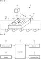
- FIG. 1 is a perspective view showing a transport device for moving batteries 1 in one embodiment
- FIG. 2 is a block diagram showing the transport device for moving batteries 1 in one embodiment.
- the transport device for moving batteries 1, according to the present disclosure may be modified in various different forms within the technical scope in which failure of a battery 100, caused by a shock that is generated when a tray 10 moves, is prevented.
- the transport device for moving batteries 1 in one embodiment comprises a conveyor belt 5, a tray 10, a shock sensor 20, a recognized member 30, a reader 40, a controller 50 and a server 60.
- the conveyor belt 5 is a mechanical one that conveys goods or materials from one point to another.
- the conveyor belt 5 operates by using the power of a motor, and moves a tray 10 placed at the upper side of the conveyor belt 5 to a predetermined place. Additional description of a detailed configuration of the conveyor belt 5 is omitted since the configuration of the conveyor belt 5 is publicly known.
- the conveyor belt 5 is provided as an example of the conveyance device.
- an applicable conveyance device is not limited to a conveyor belt.
- various types of conveyance devices capable of moving goods or materials from one point to another can be applied.
- the tray 10 moves along the conveyor belt 5, and a battery 100 is held, transferred, loaded or mounted in the tray 10.
- the tray 10 may be modified in various different forms within the technical scope in which the tray 10 conveys a battery 100.
- the tray 10 in one embodiment may be provided with a groove for mounting a battery 100. The battery 100 is inserted into the groove formed at the tray 10 and moves together with the tray 10.
- the tray 10 is illustrated as a means of loading a transported object (goods or materials; batteries), for example.
- a loading device applicable in the present disclosure is not limited to a tray.
- various types of loading devices capable of carrying goods or materials from one point to another such as a vacuum absorber or a magnetic force absorber and the like, may be used.
- the shock sensor 20 is disposed at the tray 10, and may be modified in various different forms within the technical scope in which the shock sensor 20 senses an amount of shock delivered to the tray 10.
- the shock sensor 20 is an element that generates voltage or current as an instant shock or vibration is applied.
- the shock sensor 20 may be categorized into two groups.
- the first group of shock sensors 20 is an ON/OFF-type one-axis acceleration sensor, and its output is not proportional to acceleration.
- the first group of shock sensors 20 operate an inner switch when acceleration reaches a certain value.
- the second group of shock sensors 20 is a piezoelectric element-type accelerometer, and its output is proportional to an applied shock.
- Another group of shock sensors 20 has a structure in which a spring in a shock senor 20 senses a shock, and may measure whether there is a shock.
- various types of sensors capable of sensing an amount of shock or whether there is a predetermined amount or greater of shock may be applied.
- the shock sensor 20 may directly deliver a value measured by the shock sensor 20 to the controller 50, since the shock sensor 20 directly communicates with the controller 50.
- the tray 10 may be provided with an additional communication module, such that a value measured by the shock sensor 20 and the reader 40 is delivered to the controller 50 through the communication module.
- the recognized member 30 is disposed along the path of the tray 10 and recognized by the reader 40.
- the path in which the tray 10 moves is divided into a plurality of movement areas 80, and then the recognized member 30 is installed in every movement area 80.
- the recognized member 30 is used to specify the area in which the tray 10 moves currently, and is installed in a way that the recognized member 30 is recognized by the reader 40 readily and rapidly.
- the recognized member 30 in one embodiment is a radio-frequency identification (RFID) tag.
- RFID radio-frequency identification
- the IC chip built into the RFID tag is activated, signalizes information in the chip, and sends a signal to the antenna of the tag.
- the reader 40 receives the information signal sent from the RFID tag through the antenna, and delvers the information signal to the controller 50 or the server 60, based on wired and wireless communication.
- an RFID is provided as an example of the recognized member, but the recognized member is not limited. That is, various types of recognized members may be applied depending on readers that recognize the recognized members.
- the reader 40 is disposed at the tray 10, and may be modified in various different forms within the technical scope in which the reader 40 recognizes the recognized member 30.
- the reader 40 in one embodiment is a sensor that recognizes an RFID tag.
- the shock sensor 20 and the reader 40 disposed at the tray 10 operate, measure an amount of shock delivered to the tray 10 in real time, and then deliver information on the RFID tag and information on the amount of shock to the server 60 through the controller 50.
- the reader 40 may be managed and repaired readily since the reader 40 is detachably fixed to a lateral surface of the tray 10. Additionally, the recognized member 30 that is recognized by the reader 40 may be fixedly installed in work places, and a plurality of recognized members 30 is installed respectively in predetermined places.
- the controller 50 receives the value measured by the shock sensor 20 and the reader 40, and store the same in the server 60, and may be modified in various different forms within the technical scope in which the controller 100 reduces the speed of movement of the tray 10 in the section where a predetermined value or greater of a shock is transferred to the tray 10.
- the controller 50 divides the path in which the tray 10 moves into a plurality of movement areas 80, and stores the amount of shock that is transferred to the tray 10 in every movement area 80, in the server 60.
- an amount of shock is measured each time the tray 10 moves, and the amount of shock is stored in the server 60.
- the controller 50 calculates a shock area 82 in which a predetermined amount or greater of shock is transferred to the tray 10, based on the information stored in the server 60, and reduces the speed of movement of the tray 10 in the shock area 82.
- the reader 40 of the tray 10 recognizes the fist recognized member 30-1, and then the shock sensor 20 of the tray 10 measures a predetermined reference amount or greater of shock before the reader 40 recognizes the second recognized member 30-2, the amount of shock is stored in the server 60.
- the predetermined reference amount of shock may be a maximum allowable shock that causes no damage to a battery.
- the shock sensor 20 of the tray 10 measures the predetermined reference amount or less of shock before the reader 40 recognizes the third recognized member 30-3, the amount of shock is stored in the server 60.
- the controller 50 decrease the speed of the conveyor belt 5 until the reader 40 of the following tray 10 recognizes the second recognized member 30-2, and increases the speed of the conveyor belt 5 to the original speed, as the reader 40 of the following tray 10 recognizes the second recognized member 30-2 again.
- the controller 50 may increase the speed of the conveyor belt 5 to a speed greater than the original speed, in the area where an amount of shock measured by the shock sensor 20 of the tray 10 is much less than the predetermined reference amount of shock, e.g., a maximum allowable amount of shock.
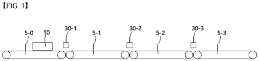
- a first conveyance device 5-1 the speed of which is controllable independently with respect to the conveyance devices 5-0, 5-2, 5-3 in the other areas
- a second conveyance device 5-2 the speed of which is controllable independently with respect to the conveyance devices 5-0, 5-1, 5-3 in the other areas
- the speed of the conveyance device is controllable independently in each area that is divided by the recognized members. Accordingly, the adjustment of speed in any one area does not affect the adjustment of speed in another area.
- a conveyance device may be configured in a way that a first conveyor belt the speed of which is controllable independently is installed between a first RFID and a second RFID, and a second conveyor belt the speed of which is controllable independently is installed between the second RFID and a third RFID.
- the above configuration may be applied in the case where a conveyance device is fixedly installed in a predetermined area, and a loading device for a transported object is moved by the conveyance device. That is, in the case where the tray 10 moves by riding on the conveyor belt 5, the tray 10 does not move on its own, and is carried by the conveyor belt 5. That is, the tray 10 is conveyed by the conveyor belt 5 as a conveyance device.
- the areas divided by the recognized members do not need to correspond to or match the areas in which the speed of the conveyance device is independently controllable, substantially.
- the controller 50 can increase the speed of the first conveyance device 5-1 and the second conveyance device 5-2, as the tray 10 recognizes the first recognized member 30-1, and control the speed of the second conveyance device 5-2 and the third conveyance device 5-3 to the original speed, as the tray 10 recognizes the second recognized member 30-2.
- a conveyance device is disposed at the loading device for a transported object, the subject matter of the present disclosure is applicable.
- control can be performed as described above. That is, as the tray 10 recognizes the first recognized member 30-1, the controller 50 can control the motor of the tray 10 to decrease the speed of movement of the tray 10, and as the tray 10 recognizes the second recognized member 30-2, the controller 50 can control the motor of the tray 10 to increase the speed of movement of the tray 10 to the original speed.
- FIG. 5 is a view showing that a shock area 82 is included in a first path L1 in one embodiment
- FIG. 6 is a view showing that a shock area 82 is included in a second path L2 in one embodiment.
- the controller 50 displays a movement area 80, in the form of a hazard map 70, based on a weight-calculated average 86 and an identification number 84 that are stored in the server 60. Additionally, the controller 50 adjusts the speed of movement of the tray 10, based on information on an amount of shock displayed in the hazard map 70.
- the controller 50 divides a work space in which the tray 10 moves into a plurality of sections, and gives an identification number 84 to each movement area 80. Then the controller 50 inputs a weight-calculated average 86 in association with the identification number 84.
- the controller 50 calculates an amount of shock transferred to the tray 10 as values from 0 to 1000, and stores a weight-calculated average 86 in which an amount of immediately preceding shock is calculated by putting weight, in the server 60.
- Formula 1 is to calculate an amount of shock I that is a weight-calculated average 86.
- ⁇ denotes weight
- N denotes a value that is calculated by deducting 1 from a total number of measurement of an amount of shock
- t denotes the number of measurement of an amount of shock.
- weight ⁇ is greater than or the same as 0.7 and less than or the same 1.
- the amount of shock I that is calculated based on formula 1 described above and is a weight-calculated average 86 is accumulated. Accordingly, even when an amount of shock measured in an instant is abnormally outstanding, the amount of shock is accumulated without being applied immediately.
- the outstanding amount of shock is caused by an error of a sensor and the like, an amount of shock following the amount of shock returns to a normal amount. Accordingly, the outstanding data value has almost no or no effect on control.
- the outstanding amount of shock is caused by a change in a facility or damage to a facility and the like, the outstanding amount of shock is continuously accumulated and reflected, and affects control.
- the amount of shock I that is calculated based on formula 1 described above and is a weight-calculated average 86 gives large weight to an amount of immediately preceding shock, such that the controller responds to a changing work environment rapidly.
- the tray 10 may move in the first path L1, and when necessary, may move in the second path L2 different from the first path L 1. If the path of the tray 10 changes, a shock affecting the tray 10 in a certain movement area 80 may be the same or similar.
- a shock area 82 of the first path L1 and a shock area 83 of the second path L2 may differ from each other.
- the controller 50 determines the speed of movement of the tray 10, with reference to a weight-calculated average 86 and a shock area 82 and the like that are stored in relation to each movement area 80.
- the controller 50 databases information on amounts of shock that are measured while the tray 10 passes the recognized member 30, for all the space, and then store the information in the server 60.
- controller 50 may adjust the speed of movement of the tray 10 by applying an algorithm for reducing a speed, when the tray 10 moves to a point affected by a large amount of shock.
- the controller 50 displays an amount of shock within values of 0 to 1000.
- the controller 50 stores a weight-calculated average 86, by giving large weight to an amount of immediately preceding shock. Thus, great importance is put on updated data.
- V t V t ⁇ 1 ⁇ log 1000 1000 ⁇ ⁇ ⁇ I
- Vt denotes the tray 10's speed to be changed
- V t-1 denotes the tray 10's current speed
- ⁇ denotes a weight parameter of an amount of shock
- I denotes an amount of shock in a corresponding section of the movement area 80.
- Vt is calculated as 0.38m/s.
- the tray 10 may travel at a speed of 0.38m/s that is 24% less than 0.5m/s.
- the controller 50 may create a hazard map 90, based on a value that is calculated based on a value stored in the server 60.
- a unique identification number 84 is given to each section of the movement area 80, and as an average of amounts of shock, a weight-calculated average 86 is recorded in relation to each identification number 84.
- the controller 50 may adjust the speed of movement of the tray 10, based on a weight-calculated average 86 of a movement area 80 corresponding to a next movement point of the tray 10.
- the speed of movement of the tray 10 may be adjusted by adjusting the speed of operation of the conveyor belt 5. As the controller 50 controls the speed of rotation of the motor provided at the conveyor belt 5, the speed of movement of the tray 10 is adjusted.
- the controller 50 may form a zone comprised of a plurality of movement areas 80 along a path of movement of the tray 10, and set an area in which a weight-calculated average 86 is a predetermined value or greater, to a shock area 82, among the plurality of movement areas 80.
- the movement area 80 of Tag9 in FIG. 5 is set to a shock area 82. Accordingly, the controller 50 decreases the speed of the tray 10 moving in the shock area 82, to lessen a shock transferred to the tray 10.
- an amount of shock is accumulated in a way that a recently measured value is mainly reflected by a weight-calculated average 86.
- results of an increase in the amount of shock generated in the movement area of Tag5 are updated as illustrated FIG. 6 , the movement areas 80 of Tag9 and Tag5 in which a weight-calculated average 86 is 300 or greater may be set to a shock area 82.
- the current situation of the transport device for moving batteries 1 can be properly controlled.
- one shock sensor 20 and one reader 40 are provided, for example. However, even if two or more shock sensors 20 and readers 40 are provided, the objectives of the present disclosure can be achieved, certainly.
- server 60 and the controller 50 may be installed integrally, and the position and number of the servers 60 may vary.
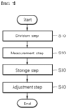
- FIG. 7 is a flowchart showing a control method of a transport device for moving batteries 1 in one embodiment.
- the control method of a transport device for moving batteries 1 in one embodiment comprises a division step (S10) in which a controller 50 divides a path of a tray 10 into a plurality of movement areas 80.
- the controller 50 divides the space in which the tray 10 moves into a plurality of movement areas 80, and a recognized member 30 is installed in each movement area 80.
- control method comprises a measurement step (S20) in which a reader 40 disposed at the tray 10 measures the recognized member 30 installed in the movement area 80, and a shock sensor 20 disposed at the tray 10 senses an amount of shock transferred to the tray 10.
- the shock sensor 20 and the reader 40 are disposed at the tray 10 moving along a conveyor belt 5, the shock sensor 20 measures a shock transferred to the tray 10 and delivers the measurements to the controller 50.
- the reader 40 measures the recognized member 30 and delivers a movement area 80 in which the tray 10 passes to the controller 50.
- control method comprises a storage step (S30) in which the controller 50 receives values measured by the shock sensor 20 and the reader 40 and stores the values in a server 60.
- the controller 50 divides the values measured by the reader 40 and the shock sensor 20, in relation to each movement area 80, and stores the values in the server 60.
- control method comprises a adjustment step (S40) in which the controller 50 adjusts the speed of movement of the tray 10, based on the measured values stored in the storage step.
- the controller 50 calculates the speed of movement of the tray 10 by using formula 2, and then adjusts the speed of movement of the conveyor belt 5. Accordingly, since the speed of movement of the tray 10 decreases in a shock area 82, a shock transferred to the tray 10 may decrease.
- the controller 50 may predict a shock that may cause failure of a battery 100, and control the speed of movement of the tray 10.
- controller 50 decreases the speed of movement of the tray 10 in a section where there is a large amount of shock, as described above, damage to a battery 100 in the tray 10 may be minimized, and a ratio of defective batteries 100 may decrease.
- a weight-calculated average 86 is calculated by giving weight to an amount of immediately preceding shock transferred to the tray 10, an amount of shock transferred to the tray 10 and a ratio of defective batteries 100 may decrease.
Landscapes
- Engineering & Computer Science (AREA)
- Manufacturing & Machinery (AREA)
- Chemical & Material Sciences (AREA)
- Chemical Kinetics & Catalysis (AREA)
- Electrochemistry (AREA)
- General Chemical & Material Sciences (AREA)
- Control Of Conveyors (AREA)
Abstract
Description
- This application claims priority to and the benefit of
Korean Patent Application No. 10-2021-0152518, filed on November 08, 2021 - The present disclosure relates to a transport device for moving batteries and a control method thereof, and in particular, a transport device for moving batteries and a control method thereof that ensure a reduction in the amount of shock transferred to a tray conveying batteries.
- Ordinarily, batteries convert chemical energy to electric energy. Two or more cells connect, and current flows in the same direction, to form a battery.
- Batteries are produced through a variety of processes, and move for each process in the state where the batteries are contained in a tray.
- The tray containing the batteries moves at a constant speed in a product line where each process proceeds. The transport path of the tray on which the batteries are stacked is not always gentle and smooth. The tray moving at a constant speed is not affected by a shock in one area but is affected in another area. A shock transferred to the tray during transportation can damage the batteries stacked on the tray.
- In the area where a shock is predicted while the tray moves, e.g., the area where there is a stopper, the speed of the tray can decrease in advance, such that the shock affecting the tray can lessen. However, in the area where a shock cannot be predicted, the tray cannot help being affected by the shock.
- Additionally, as time passes, transport devices such as a conveyor belt wear. Thus, another shock can be generated in the area where no shock is generated previously.
- To prevent the batteries stacked on the tray from being damaged by an unpredicted shock, an amount of shock affecting the tray during transportation needs to be sensed continuously.
- The background art of the present disclosure is disclosed in
KR Patent Publication No. 2020-0087562 (July 21, 2020 - The obj ective of the present disclosure is to provide a transport device for moving batteries and a control method thereof that can ensure a reduction in the amount of shock transferred to a tray conveying batteries.
- The obj ective of the present disclosure is to provide a transport device for moving batteries and a control method thereof that can adjust the speed of movement of a tray in the case where the tray moves to a point where a large amount of shock is generated.
- The objective of the present disclosure is to provide a transport device for moving batteries and a control method thereof that can adjust the speed of movement of a tray in the case where the tray moves to the point where a very small amount of shock is generated, or the tray moves in the area where no shock is generated.
- Aspects according to the present disclosure are not limited to the above ones, and other aspects and advantages that are not mentioned above can be clearly understood from the following description and can be more clearly understood from the embodiments set forth herein. Additionally, the aspects and advantages in the present disclosure can be realized via means and combinations thereof that are described in the appended claims.
- A transport device for moving batteries and a control method thereof, according to the present disclosure, can adjust the speed of movement of a tray, to reduce the amount of shock transferred to a tray conveying batteries.
- Specifically, according to the present disclosure, a path of movement of a tray is divided into a plurality of areas, and in the section where a large amount of shock is transferred to the tray, the speed of movement of the tray decreases, to reduce damage to batteries in the tray.
- Further, according to the present disclosure, in the area where a tray is not affected by a shock, the speed of movement of the tray increases, to speed up the conveyance of batteries.
- A transport device for moving batteries in one embodiment comprises a tray which conveys batteries while moving along a conveyor belt, a shock sensor that is disposed at the tray, and senses an amount of shock transferred to the tray, one or more recognized members that are installed along a path of the tray, a reader that is disposed at the tray, and recognizes the one or more recognized members, and a controller that receives values measured by the shock sensor and receive recognized member information from the reader and stores the values in a server, determines a movement area from among the plurality of movement areas in which a predetermined amount of shock or greater is transferred to the tray based on the received values and recognized member information, and decreases a speed of movement of the tray at the determined movement area.
- The one or more recognized members are a radio-frequency identification (RFID) tags, and the reader uses a sensor recognizing RFID tags.
- Additionally, the one or more recognized members may be a plurality of recognized members, whereby each recognized member is installed at a respective movement area of the plurality of movement areas.
- The controller determines an amount of shock transferred to the tray in the server, in relation to each of the movement areas.
- The controller calculates a shock area in which a predetermined amount or greater of shock is transferred to the tray, based on information stored in the server, and in the shock area, deceases the speed of movement of the tray.
- A control method of a transport device for moving batteries in one embodiment comprises dividing, by a controller, a path of a tray into a plurality of movement areas, recognizing, by a reader disposed at the tray, a recognized member installed areas along the path of the tray, sensing, by a shock sensor disposed at the tray, an amount of shock transferred to the tray, receiving, by the controller, values measured by the shock sensor and recognized member information from the reader, and adjusting, by the controller, a speed of movement of the tray being moved along the path by a conveyance device, based on the received values and recognized member information.
- The recognized member is a radio-frequency identification (RFID) tag, and the reader uses a sensor recognizing an RFID tag.
- The method further includes assigning, by the controller, a corresponding identification number to each respective movement area of the plurality of movement areas, determining, for each respective movement area, an amount of shock in the respective movement area, and storing, for each respective movement area, the determined amount of shock together with the corresponding identification number of the respective movement area.
- Sensing the amount of shock transferred to the tray includes calculating, by the controller, the amount of shock as a value from 0 to 1000, and storing a weight-calculated average of the amount of shock, wherein the weight-calculated average for a given shock measurement is calculated by putting weight to immediately preceding shock measurement.
- The method further includes displaying, by the controller, the plurality of movement areas in a hazard map form, based on weight-calculated averages for each movement area and corresponding identification numbers stored in the server, and adjusting the speed of movement of the tray, based on information on the amount of shock transferred to the tray displayed in the hazard map.
- In a transport device for moving batteries and a control method thereof according to the present disclosure, a controller decreases the speed of movement of a tray in the section where a large amount of shock is generated, thereby minimizing damage to batteries in the tray and reducing a ratio of defective batteries.
- In the transport device for moving batteries and the control method thereof, the speed of movement of a tray increases in the area where almost no shock is generated or a shock rarely increases despite an increase in the speed of the tray, thereby enhancing the tray's efficiency of transporting batteries.
- In the transport device for moving batteries and the control method thereof, a weight-calculated average is calculated by giving weight to an amount of immediately preceding shock transferred to a tray, thereby reducing the amount of the shock transferred to the tray and a ratio of defective batteries.
- Specific effects are described along with the above-described effects in the section of detailed description.
-
-
FIG. 1 is a perspective view showing a transport device for moving batteries in one embodiment. -
FIG. 2 is a block diagram showing the transport device for moving batteries in one embodiment. -
FIGS. 3 and4 are views respectively showing examples of a recognized member and a conveyance device that are disposed in a path of a transport device for moving batteries. -
FIG. 5 is a view showing that a shock area is included in a first path in one embodiment. -
FIG. 6 is a view showing that a shock area is included in a second path in one embodiment. -
FIG. 7 is a flowchart showing a control method of a transport device for moving batteries in one embodiment. - 1: Transport device for moving batteries 5: Conveyor belt 10: Tray 20: Shock sensor 30: Recognized member 40: Reader 50: Controller 60: Server 70: Hazard map 80:
Path 82,83: Shock area 84: Identification number 86: Weight-calculated average 100: Battery L1: First path L2: Second path S10: Division step S20: Measurement step S30: Storage step S40: Adjustment step - The above-described aspects, features and advantages are specifically described hereafter with reference to the accompanying drawings such that one having ordinary skill in the art to which the present disclosure pertains can embody the technical spirit of the disclosure easily. In the disclosure, detailed description of known technologies in relation to the subject matter of disclosure is omitted if it is deemed to make the gist of the disclosure unnecessarily vague. Hereafter, preferred embodiments according to the disclosure are specifically described with reference to the accompanying drawings. In the drawings, identical reference numerals can denote identical or similar components.
- The terms "first", "second" and the like are used herein only to distinguish one component from another component. Thus, the components should not be limited by the terms. Certainly, a first component can be a second component, unless stated to the contrary.
- When any one component is described as being "in the upper portion (or lower potion)" or "on (or under)" another component, any one component can be directly on (or under) another component, but an additional component can be interposed between any one component and another component on (or under) any one component.
- When any one component is described as being "connected", "coupled", or "connected" to another component, any one component can be directly connected or coupled to another component, but an additional component can be "interposed" between the two components or the two components can be "connected", "coupled", or "connected" by an additional component.
- Throughout the disclosure, each component can be provided as a single one or a plurality of ones, unless explicitly stated to the contrary.
- The singular forms "a", "an" and "the" are intended to include the plural forms as well, unless explicitly indicated otherwise. It is to be understood that the terms "comprise" or "include" and the like, set forth herein, are not interpreted as necessarily including all the stated components or steps but can be interpreted as excluding some of the stated components or steps or can be interpreted as including additional components or steps.
- Throughout the disclosure, the phrase "A and/or B" as used herein can denote A, B or A and B, and the phrase "C to D" can denote C or greater and D or less, unless stated to the contrary.
- Hereafter, a transport device for moving batteries 1 and a control method thereof in one embodiment are described.
-
FIG. 1 is a perspective view showing a transport device for moving batteries 1 in one embodiment, andFIG. 2 is a block diagram showing the transport device for moving batteries 1 in one embodiment. - As illustrated in
FIGS. 1 and 2 , the transport device for moving batteries 1, according to the present disclosure, may be modified in various different forms within the technical scope in which failure of abattery 100, caused by a shock that is generated when atray 10 moves, is prevented. - The transport device for moving batteries 1 in one embodiment comprises a
conveyor belt 5, atray 10, ashock sensor 20, a recognizedmember 30, areader 40, acontroller 50 and aserver 60. - The
conveyor belt 5 is a mechanical one that conveys goods or materials from one point to another. Theconveyor belt 5 operates by using the power of a motor, and moves atray 10 placed at the upper side of theconveyor belt 5 to a predetermined place. Additional description of a detailed configuration of theconveyor belt 5 is omitted since the configuration of theconveyor belt 5 is publicly known. - In the embodiment, the
conveyor belt 5 is provided as an example of the conveyance device. However, in the present disclosure, an applicable conveyance device is not limited to a conveyor belt. In addition to a conveyance belt, various types of conveyance devices capable of moving goods or materials from one point to another can be applied. - The
tray 10 moves along theconveyor belt 5, and abattery 100 is held, transferred, loaded or mounted in thetray 10. Thetray 10 may be modified in various different forms within the technical scope in which thetray 10 conveys abattery 100. Thetray 10 in one embodiment may be provided with a groove for mounting abattery 100. Thebattery 100 is inserted into the groove formed at thetray 10 and moves together with thetray 10. - In the embodiment, the
tray 10 is illustrated as a means of loading a transported object (goods or materials; batteries), for example. However, a loading device applicable in the present disclosure is not limited to a tray. In addition to a tray, various types of loading devices capable of carrying goods or materials from one point to another, such as a vacuum absorber or a magnetic force absorber and the like, may be used. - The
shock sensor 20 is disposed at thetray 10, and may be modified in various different forms within the technical scope in which theshock sensor 20 senses an amount of shock delivered to thetray 10. - The
shock sensor 20 is an element that generates voltage or current as an instant shock or vibration is applied. Theshock sensor 20 may be categorized into two groups. The first group ofshock sensors 20 is an ON/OFF-type one-axis acceleration sensor, and its output is not proportional to acceleration. The first group ofshock sensors 20 operate an inner switch when acceleration reaches a certain value. - The second group of
shock sensors 20 is a piezoelectric element-type accelerometer, and its output is proportional to an applied shock. - Another group of
shock sensors 20 has a structure in which a spring in ashock senor 20 senses a shock, and may measure whether there is a shock. - In addition to the above-mentioned sensors, various types of sensors capable of sensing an amount of shock or whether there is a predetermined amount or greater of shock may be applied.
- The
shock sensor 20 may directly deliver a value measured by theshock sensor 20 to thecontroller 50, since theshock sensor 20 directly communicates with thecontroller 50. Alternatively, thetray 10 may be provided with an additional communication module, such that a value measured by theshock sensor 20 and thereader 40 is delivered to thecontroller 50 through the communication module. - The recognized
member 30 is disposed along the path of thetray 10 and recognized by thereader 40. In one embodiment, the path in which thetray 10 moves is divided into a plurality ofmovement areas 80, and then the recognizedmember 30 is installed in everymovement area 80. - The recognized
member 30 is used to specify the area in which thetray 10 moves currently, and is installed in a way that the recognizedmember 30 is recognized by thereader 40 readily and rapidly. - The recognized
member 30 in one embodiment is a radio-frequency identification (RFID) tag. The RFID tag is installed in each section of themovement area 80 of thetray 10. - The IC chip built into the RFID tag is activated, signalizes information in the chip, and sends a signal to the antenna of the tag. The
reader 40 receives the information signal sent from the RFID tag through the antenna, and delvers the information signal to thecontroller 50 or theserver 60, based on wired and wireless communication. - In the embodiment, an RFID is provided as an example of the recognized member, but the recognized member is not limited. That is, various types of recognized members may be applied depending on readers that recognize the recognized members.
- The
reader 40 is disposed at thetray 10, and may be modified in various different forms within the technical scope in which thereader 40 recognizes the recognizedmember 30. Thereader 40 in one embodiment is a sensor that recognizes an RFID tag. - The
shock sensor 20 and thereader 40 disposed at thetray 10 operate, measure an amount of shock delivered to thetray 10 in real time, and then deliver information on the RFID tag and information on the amount of shock to theserver 60 through thecontroller 50. - The
reader 40 may be managed and repaired readily since thereader 40 is detachably fixed to a lateral surface of thetray 10. Additionally, the recognizedmember 30 that is recognized by thereader 40 may be fixedly installed in work places, and a plurality of recognizedmembers 30 is installed respectively in predetermined places. - The
controller 50 receives the value measured by theshock sensor 20 and thereader 40, and store the same in theserver 60, and may be modified in various different forms within the technical scope in which thecontroller 100 reduces the speed of movement of thetray 10 in the section where a predetermined value or greater of a shock is transferred to thetray 10. - The
controller 50 divides the path in which thetray 10 moves into a plurality ofmovement areas 80, and stores the amount of shock that is transferred to thetray 10 in everymovement area 80, in theserver 60. - For example, in the case where the
tray 10 moves ten times, an amount of shock is measured each time thetray 10 moves, and the amount of shock is stored in theserver 60. - The
controller 50 calculates ashock area 82 in which a predetermined amount or greater of shock is transferred to thetray 10, based on the information stored in theserver 60, and reduces the speed of movement of thetray 10 in theshock area 82. - Referring to
FIGS. 3 and4 , in a path of thetray 10, where a first recognized member 30-1, a second recognized member 30-2, and a third recognized member 30-3 are placed in order, if thereader 40 of thetray 10 recognizes the fist recognized member 30-1, and then theshock sensor 20 of thetray 10 measures a predetermined reference amount or greater of shock before thereader 40 recognizes the second recognized member 30-2, the amount of shock is stored in theserver 60. The predetermined reference amount of shock may be a maximum allowable shock that causes no damage to a battery. Additionally, if thereader 40 of thetray 10 recognizes the second recognized member 30-2, and theshock sensor 20 of thetray 10 measures the predetermined reference amount or less of shock before thereader 40 recognizes the third recognized member 30-3, the amount of shock is stored in theserver 60. - Then, in the case where a following
tray 10 moves in the path, as thereader 40 of the followingtray 10 recognizes the first recognized member 30-1, thecontroller 50 decrease the speed of theconveyor belt 5 until thereader 40 of the followingtray 10 recognizes the second recognized member 30-2, and increases the speed of theconveyor belt 5 to the original speed, as thereader 40 of the followingtray 10 recognizes the second recognized member 30-2 again. - In the expansion of this concept, to enhance transport efficiency, the
controller 50 may increase the speed of theconveyor belt 5 to a speed greater than the original speed, in the area where an amount of shock measured by theshock sensor 20 of thetray 10 is much less than the predetermined reference amount of shock, e.g., a maximum allowable amount of shock. - When the area which is divided by the recognized members substantially corresponds to or matches the area where the speed of the conveyance device is independently controlled, transport efficiency improves further.
- If a first conveyance device 5-1, the speed of which is controllable independently with respect to the conveyance devices 5-0, 5-2, 5-3 in the other areas, is installed in an area between the first recognized member 30-1 and the second recognized member 30-2, and a second conveyance device 5-2, the speed of which is controllable independently with respect to the conveyance devices 5-0, 5-1, 5-3 in the other areas, is installed in a area between the second recognized member 30-2 and the third recognized member 30-3, as illustrated in
FIG. 3 , the speed of the conveyance device is controllable independently in each area that is divided by the recognized members. Accordingly, the adjustment of speed in any one area does not affect the adjustment of speed in another area. - Specifically, a conveyance device may be configured in a way that a first conveyor belt the speed of which is controllable independently is installed between a first RFID and a second RFID, and a second conveyor belt the speed of which is controllable independently is installed between the second RFID and a third RFID.
- The above configuration may be applied in the case where a conveyance device is fixedly installed in a predetermined area, and a loading device for a transported object is moved by the conveyance device. That is, in the case where the
tray 10 moves by riding on theconveyor belt 5, thetray 10 does not move on its own, and is carried by theconveyor belt 5. That is, thetray 10 is conveyed by theconveyor belt 5 as a conveyance device. - However, in the technical scope of the present disclosure, the areas divided by the recognized members do not need to correspond to or match the areas in which the speed of the conveyance device is independently controllable, substantially.
- Even if a portion of the first conveyance device 5-1 and a portion of the second conveyance device 5-2 are disposed between the first recognized member 30-1 and the second recognized member 30-2, and a portion of the second conveyance device 5-2 and a portion of the third conveyance device 5-3 are disposed between the second recognized member 30-2 and the third recognized member 30-3, as illustrated in
FIG. 4 , the subject matter of the present disclosure is certainly applicable. Even in the above arrangement, thecontroller 50 can increase the speed of the first conveyance device 5-1 and the second conveyance device 5-2, as thetray 10 recognizes the first recognized member 30-1, and control the speed of the second conveyance device 5-2 and the third conveyance device 5-3 to the original speed, as thetray 10 recognizes the second recognized member 30-2. - Even if a conveyance device is disposed at the loading device for a transported object, the subject matter of the present disclosure is applicable. Even in the case of a transport device for moving batteries, where a
tray 10 is provided with a motor and wheels such that thetray 10 moves on its own, control can be performed as described above. That is, as thetray 10 recognizes the first recognized member 30-1, thecontroller 50 can control the motor of thetray 10 to decrease the speed of movement of thetray 10, and as thetray 10 recognizes the second recognized member 30-2, thecontroller 50 can control the motor of thetray 10 to increase the speed of movement of thetray 10 to the original speed. -
FIG. 5 is a view showing that ashock area 82 is included in a first path L1 in one embodiment, andFIG. 6 is a view showing that ashock area 82 is included in a second path L2 in one embodiment. - As illustrated in
FIGS. 2 to 6 , thecontroller 50 displays amovement area 80, in the form of ahazard map 70, based on a weight-calculatedaverage 86 and anidentification number 84 that are stored in theserver 60. Additionally, thecontroller 50 adjusts the speed of movement of thetray 10, based on information on an amount of shock displayed in thehazard map 70. - The
controller 50 divides a work space in which thetray 10 moves into a plurality of sections, and gives anidentification number 84 to eachmovement area 80. Then thecontroller 50 inputs a weight-calculated average 86 in association with theidentification number 84. - The
controller 50 calculates an amount of shock transferred to thetray 10 as values from 0 to 1000, and stores a weight-calculated average 86 in which an amount of immediately preceding shock is calculated by putting weight, in theserver 60. - For example, in the case where a weight-calculated
average 86 is "536" in amovement area 80 input as anidentification number 84 of "Tag9", thecontroller 50 associates "Tag9" and "536" and stores the same in theserver 60.
- Formula 1 is to calculate an amount of shock I that is a weight-calculated
average 86. In formula 1, α denotes weight, N denotes a value that is calculated by deducting 1 from a total number of measurement of an amount of shock, and t denotes the number of measurement of an amount of shock. - In formula 1, It denotes an amount of shock measured last, and weight α is greater than or the same as 0.7 and less than or the same 1.
- The amount of shock I that is calculated based on formula 1 described above and is a weight-calculated
average 86 is accumulated. Accordingly, even when an amount of shock measured in an instant is abnormally outstanding, the amount of shock is accumulated without being applied immediately. - If the outstanding amount of shock is caused by an error of a sensor and the like, an amount of shock following the amount of shock returns to a normal amount. Accordingly, the outstanding data value has almost no or no effect on control.
- If the outstanding amount of shock is caused by a change in a facility or damage to a facility and the like, the outstanding amount of shock is continuously accumulated and reflected, and affects control.
- At this time, the amount of shock I that is calculated based on formula 1 described above and is a weight-calculated
average 86 gives large weight to an amount of immediately preceding shock, such that the controller responds to a changing work environment rapidly. - Further, the
tray 10 may move in the first path L1, and when necessary, may move in the second path L2 different from the first path L 1. If the path of thetray 10 changes, a shock affecting thetray 10 in acertain movement area 80 may be the same or similar. - If the path of the
tray 10 changes, ashock area 82 of the first path L1 and a shock area 83 of the second path L2 may differ from each other. - Even if the path of the
tray 10 changes, thecontroller 50 determines the speed of movement of thetray 10, with reference to a weight-calculatedaverage 86 and ashock area 82 and the like that are stored in relation to eachmovement area 80. - As illustrated in
FIGS. 1 to 6 , thecontroller 50 databases information on amounts of shock that are measured while thetray 10 passes the recognizedmember 30, for all the space, and then store the information in theserver 60. - Additionally, the
controller 50 may adjust the speed of movement of thetray 10 by applying an algorithm for reducing a speed, when thetray 10 moves to a point affected by a large amount of shock. - The
controller 50 displays an amount of shock within values of 0 to 1000. When storing an amount of shock in theserver 60, thecontroller 50 stores a weight-calculatedaverage 86, by giving large weight to an amount of immediately preceding shock. Thus, great importance is put on updated data.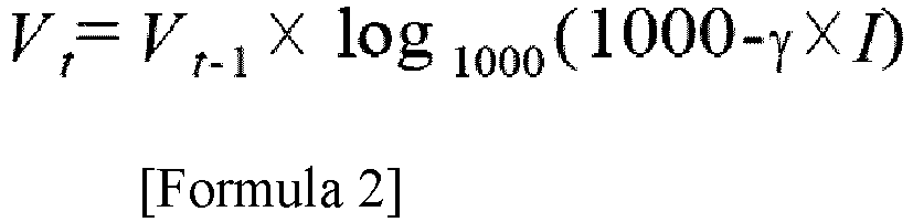
- In formula 2, Vt denotes the
tray 10's speed to be changed, Vt-1 denotes thetray 10's current speed, γ denotes a weight parameter of an amount of shock, and I denotes an amount of shock in a corresponding section of themovement area 80. - For example, in the case where the current speed of the
tray 10 is 0.5m/s at a time when thetray 10 moves from Tag15 to Tag9, Vt is calculated as 0.38m/s. - Accordingly, the
tray 10 may travel at a speed of 0.38m/s that is 24% less than 0.5m/s. - Additionally, the
controller 50 may create a hazard map 90, based on a value that is calculated based on a value stored in theserver 60. In thehazard map 70, aunique identification number 84 is given to each section of themovement area 80, and as an average of amounts of shock, a weight-calculatedaverage 86 is recorded in relation to eachidentification number 84. - Thus, the
controller 50 may adjust the speed of movement of thetray 10, based on a weight-calculatedaverage 86 of amovement area 80 corresponding to a next movement point of thetray 10. - The speed of movement of the
tray 10 may be adjusted by adjusting the speed of operation of theconveyor belt 5. As thecontroller 50 controls the speed of rotation of the motor provided at theconveyor belt 5, the speed of movement of thetray 10 is adjusted. - The
controller 50 may form a zone comprised of a plurality ofmovement areas 80 along a path of movement of thetray 10, and set an area in which a weight-calculatedaverage 86 is a predetermined value or greater, to ashock area 82, among the plurality ofmovement areas 80. - For example, in the case where an area in which a weight-calculated
average 86 is 300 or greater is set as ashock area 82, themovement area 80 of Tag9 inFIG. 5 is set to ashock area 82. Accordingly, thecontroller 50 decreases the speed of thetray 10 moving in theshock area 82, to lessen a shock transferred to thetray 10. - According to the present disclosure, an amount of shock is accumulated in a way that a recently measured value is mainly reflected by a weight-calculated
average 86. Thus, as time passes, wear on the conveyance device and the like, and a change in the amount of shock caused by a renewal of the conveyance device based on management and repairs can be smoothly dealt with. - For example, in the case where results of an increase in the amount of shock generated in the movement area of Tag5, as time passes from the time point when the
hazard map 70 inFIG. 5 is created, are updated as illustratedFIG. 6 , themovement areas 80 of Tag9 and Tag5 in which a weight-calculatedaverage 86 is 300 or greater may be set to ashock area 82. According to the present disclosure, the current situation of the transport device for moving batteries 1 can be properly controlled. - In one embodiment, one
shock sensor 20 and onereader 40 are provided, for example. However, even if two ormore shock sensors 20 andreaders 40 are provided, the objectives of the present disclosure can be achieved, certainly. - Though not illustrated, the
server 60 and thecontroller 50 may be installed integrally, and the position and number of theservers 60 may vary. - Hereafter, a control method of a transport device for moving batteries 1 in one embodiment is described with reference to the accompanying drawings.
-
FIG. 7 is a flowchart showing a control method of a transport device for moving batteries 1 in one embodiment. - As illustrated in
FIG. 7 , the control method of a transport device for moving batteries 1 in one embodiment comprises a division step (S10) in which acontroller 50 divides a path of atray 10 into a plurality ofmovement areas 80. - The
controller 50 divides the space in which thetray 10 moves into a plurality ofmovement areas 80, and a recognizedmember 30 is installed in eachmovement area 80. - Additionally, the control method comprises a measurement step (S20) in which a
reader 40 disposed at thetray 10 measures the recognizedmember 30 installed in themovement area 80, and ashock sensor 20 disposed at thetray 10 senses an amount of shock transferred to thetray 10. - Since the
shock sensor 20 and thereader 40 are disposed at thetray 10 moving along aconveyor belt 5, theshock sensor 20 measures a shock transferred to thetray 10 and delivers the measurements to thecontroller 50. - The
reader 40 measures the recognizedmember 30 and delivers amovement area 80 in which thetray 10 passes to thecontroller 50. - Additionally, the control method comprises a storage step (S30) in which the
controller 50 receives values measured by theshock sensor 20 and thereader 40 and stores the values in aserver 60. - The
controller 50 divides the values measured by thereader 40 and theshock sensor 20, in relation to eachmovement area 80, and stores the values in theserver 60. - Additionally, the control method comprises a adjustment step (S40) in which the
controller 50 adjusts the speed of movement of thetray 10, based on the measured values stored in the storage step. - The
controller 50 calculates the speed of movement of thetray 10 by using formula 2, and then adjusts the speed of movement of theconveyor belt 5. Accordingly, since the speed of movement of thetray 10 decreases in ashock area 82, a shock transferred to thetray 10 may decrease. - The
controller 50 may predict a shock that may cause failure of abattery 100, and control the speed of movement of thetray 10. - Since the
controller 50 according to the present disclosure decreases the speed of movement of thetray 10 in a section where there is a large amount of shock, as described above, damage to abattery 100 in thetray 10 may be minimized, and a ratio ofdefective batteries 100 may decrease. - Further, since a weight-calculated
average 86 is calculated by giving weight to an amount of immediately preceding shock transferred to thetray 10, an amount of shock transferred to thetray 10 and a ratio ofdefective batteries 100 may decrease. - The embodiments are described above with reference to a number of illustrative embodiments thereof. However, embodiments are not limited to the embodiments and drawings set forth herein, and numerous other modifications and embodiments can be drawn by one skilled in the art within the technical scope of the disclosure. Further, the effects and predictable effects based on the configurations in the disclosure are to be included within the scope of the disclosure though not explicitly described in the description of the embodiments.
Claims (10)
dividing, by a controller, a path of a tray into a plurality of movement areas;
Applications Claiming Priority (2)
| Application Number | Priority Date | Filing Date | Title |
|---|---|---|---|
| KR1020210152518A KR20230066955A (en) | 2021-11-08 | 2021-11-08 | Transport device for moving batteries and control method thereof |
| PCT/KR2022/016748 WO2023080567A1 (en) | 2021-11-08 | 2022-10-28 | Transport apparatus for transferring battery and control method therefor |
Publications (2)
| Publication Number | Publication Date |
|---|---|
| EP4428067A1 true EP4428067A1 (en) | 2024-09-11 |
| EP4428067A4 EP4428067A4 (en) | 2025-03-05 |
Family
ID=86241426
Family Applications (1)
| Application Number | Title | Priority Date | Filing Date |
|---|---|---|---|
| EP22890298.7A Pending EP4428067A4 (en) | 2021-11-08 | 2022-10-28 | Transport apparatus for transferring battery and control method therefor |
Country Status (6)
| Country | Link |
|---|---|
| US (1) | US20250270058A1 (en) |
| EP (1) | EP4428067A4 (en) |
| JP (1) | JP2024540421A (en) |
| KR (1) | KR20230066955A (en) |
| CN (1) | CN118251356A (en) |
| WO (1) | WO2023080567A1 (en) |
Family Cites Families (19)
| Publication number | Priority date | Publication date | Assignee | Title |
|---|---|---|---|---|
| JP2810633B2 (en) * | 1994-11-04 | 1998-10-15 | 山一電機株式会社 | Impact measurement method in goods transportation |
| JP2002298806A (en) * | 2001-03-29 | 2002-10-11 | Tdk Corp | Battery tray, battery manufacturing method, and secondary battery manufacturing method |
| CN1950279B (en) * | 2004-04-30 | 2011-04-13 | 株式会社汤山制作所 | Medicine tray supply device |
| JP2007290817A (en) * | 2006-04-25 | 2007-11-08 | Nippon Sharyo Seizo Kaisha Ltd | Load collapse prevention device |
| KR100960145B1 (en) * | 2009-05-08 | 2010-05-27 | 주식회사 인아텍 | Apparatus for transporting an item in conveyor system |
| JP2014142190A (en) * | 2013-01-22 | 2014-08-07 | Sric Corp | Transportation information acquisition system |
| CH707879A1 (en) * | 2013-04-11 | 2014-10-15 | Ferag Ag | Control of drives of conveyor sections of a conveyor system. |
| KR101900555B1 (en) * | 2016-06-30 | 2018-11-05 | 주식회사 포스코아이씨티 | Patrol Tray, System and Method for Inspecting Tray Transfer Equipment Using Patrol Tray |
| KR102033144B1 (en) * | 2017-06-09 | 2019-10-17 | 주식회사 세일테크놀러지 | System for controlling Automated Guided Vehicle using Visible Light Communication |
| JP6998709B2 (en) * | 2017-09-11 | 2022-01-18 | 株式会社富士通エフサス | Management system, management server, management method and management program |
| KR102048615B1 (en) * | 2017-09-27 | 2020-01-08 | 주식회사 포스코아이씨티 | System and Method for Handling Baggage Using Patrol Tray |
| KR102261291B1 (en) * | 2017-11-01 | 2021-06-04 | 현대자동차 주식회사 | System and method for sequence management of vehicle |
| US10910249B2 (en) * | 2017-11-13 | 2021-02-02 | Taiwan Semiconductor Manufacturing Co., Ltd. | Systems and methods for automated wafer handling |
| JP7351054B2 (en) * | 2017-11-27 | 2023-09-27 | トーヨーカネツ株式会社 | Conveyance system inspection equipment (Doctor Logistics) |
| KR102404261B1 (en) | 2019-01-11 | 2022-05-30 | 삼성에스디아이 주식회사 | Tray for transferring battery |
| CA3136643A1 (en) | 2019-04-16 | 2020-10-22 | Bace Australia Pty Ltd | Hydroponic apparatus |
| JP7331446B2 (en) * | 2019-05-13 | 2023-08-23 | オムロン株式会社 | Control device, automatic guided vehicle, control method and control program for automatic guided vehicle |
| US11107713B2 (en) * | 2019-05-29 | 2021-08-31 | Taiwan Semiconductor Manufacturing Company Ltd. | Conveying system and method for operating the same |
| KR102242361B1 (en) * | 2019-12-10 | 2021-04-20 | 제닉스주식회사 | Trasnporting system and controlling method of transporting system |
-
2021
- 2021-11-08 KR KR1020210152518A patent/KR20230066955A/en active Pending
-
2022
- 2022-10-28 CN CN202280074275.2A patent/CN118251356A/en active Pending
- 2022-10-28 US US18/707,279 patent/US20250270058A1/en active Pending
- 2022-10-28 JP JP2024527225A patent/JP2024540421A/en active Pending
- 2022-10-28 EP EP22890298.7A patent/EP4428067A4/en active Pending
- 2022-10-28 WO PCT/KR2022/016748 patent/WO2023080567A1/en not_active Ceased
Also Published As
| Publication number | Publication date |
|---|---|
| US20250270058A1 (en) | 2025-08-28 |
| JP2024540421A (en) | 2024-10-31 |
| CN118251356A (en) | 2024-06-25 |
| WO2023080567A1 (en) | 2023-05-11 |
| EP4428067A4 (en) | 2025-03-05 |
| KR20230066955A (en) | 2023-05-16 |
Similar Documents
| Publication | Publication Date | Title |
|---|---|---|
| KR101863282B1 (en) | Multi-stage chute device for sorter, control apparatus and method thereof | |
| US9399557B1 (en) | Sensing conveyor for object characteristic determination | |
| US9233799B1 (en) | Sensing conveyor for object characteristic determination | |
| US8579186B2 (en) | System and method for tracking shipment of items utilizing RFID-tags | |
| CN112513591B (en) | Method and apparatus for identifying loads of transport elements of long stator linear motor systems | |
| US12397992B2 (en) | Storage and picking system and method for predicting and/or averting a future disruption | |
| EP3064285A1 (en) | Article sorting apparatus | |
| US20110132724A1 (en) | Transport system | |
| CN107697533B (en) | Transmission system and method | |
| US20020033361A1 (en) | Capacitor characteristics measurement and packing apparatus | |
| EP4428067A1 (en) | Transport apparatus for transferring battery and control method therefor | |
| KR100657817B1 (en) | Automatic processing system for logistics work using wireless recognition | |
| US20230406629A1 (en) | System and computer-readable storage medium | |
| JP6556796B2 (en) | Control apparatus and control method | |
| KR102688550B1 (en) | Freight sort system and method for controlling the same | |
| CN114951009A (en) | A package feeding method, four-stage feeding system, equipment and storage medium | |
| KR101995632B1 (en) | System and method for managing piled up articles | |
| JP2009075728A (en) | Radio tag reading device and its reading method | |
| JP2001206553A (en) | Raw material storage / cutout method and equipment | |
| KR102395003B1 (en) | Article recognition apparatus for sorting article | |
| KR102321643B1 (en) | Apparatus for transporting boxes to deliver drugs and a system for delivering drugs | |
| KR102544565B1 (en) | System for detecting position of carrier of sorter | |
| JP2025165759A (en) | Sorting and packaging system | |
| JPH0481625A (en) | Sorting apparatus of weight | |
| JP2006027774A (en) | Package weight management system |
Legal Events
| Date | Code | Title | Description |
|---|---|---|---|
| STAA | Information on the status of an ep patent application or granted ep patent |
Free format text: STATUS: THE INTERNATIONAL PUBLICATION HAS BEEN MADE |
|
| PUAI | Public reference made under article 153(3) epc to a published international application that has entered the european phase |
Free format text: ORIGINAL CODE: 0009012 |
|
| STAA | Information on the status of an ep patent application or granted ep patent |
Free format text: STATUS: REQUEST FOR EXAMINATION WAS MADE |
|
| 17P | Request for examination filed |
Effective date: 20240604 |
|
| AK | Designated contracting states |
Kind code of ref document: A1 Designated state(s): AL AT BE BG CH CY CZ DE DK EE ES FI FR GB GR HR HU IE IS IT LI LT LU LV MC ME MK MT NL NO PL PT RO RS SE SI SK SM TR |
|
| DAV | Request for validation of the european patent (deleted) | ||
| DAX | Request for extension of the european patent (deleted) | ||
| A4 | Supplementary search report drawn up and despatched |
Effective date: 20250131 |
|
| RIC1 | Information provided on ipc code assigned before grant |
Ipc: H01M 10/00 20060101ALI20250128BHEP Ipc: B65G 43/08 20060101AFI20250128BHEP |
|
| STAA | Information on the status of an ep patent application or granted ep patent |
Free format text: STATUS: EXAMINATION IS IN PROGRESS |
|
| 17Q | First examination report despatched |
Effective date: 20251024 |