EP4427709B1 - Manschette und orthesensystem - Google Patents
Manschette und orthesensystem Download PDFInfo
- Publication number
- EP4427709B1 EP4427709B1 EP24162058.2A EP24162058A EP4427709B1 EP 4427709 B1 EP4427709 B1 EP 4427709B1 EP 24162058 A EP24162058 A EP 24162058A EP 4427709 B1 EP4427709 B1 EP 4427709B1
- Authority
- EP
- European Patent Office
- Prior art keywords
- cuff
- lower shell
- form fit
- magnetic
- fixation element
- Prior art date
- Legal status (The legal status is an assumption and is not a legal conclusion. Google has not performed a legal analysis and makes no representation as to the accuracy of the status listed.)
- Active
Links
Images


Classifications
-
- A—HUMAN NECESSITIES
- A61—MEDICAL OR VETERINARY SCIENCE; HYGIENE
- A61F—FILTERS IMPLANTABLE INTO BLOOD VESSELS; PROSTHESES; DEVICES PROVIDING PATENCY TO, OR PREVENTING COLLAPSING OF, TUBULAR STRUCTURES OF THE BODY, e.g. STENTS; ORTHOPAEDIC, NURSING OR CONTRACEPTIVE DEVICES; FOMENTATION; TREATMENT OR PROTECTION OF EYES OR EARS; BANDAGES, DRESSINGS OR ABSORBENT PADS; FIRST-AID KITS
- A61F5/00—Orthopaedic methods or devices for non-surgical treatment of bones or joints; Nursing devices ; Anti-rape devices
- A61F5/01—Orthopaedic devices, e.g. long-term immobilising or pressure directing devices for treating broken or deformed bones such as splints, casts or braces
- A61F5/0102—Orthopaedic devices, e.g. long-term immobilising or pressure directing devices for treating broken or deformed bones such as splints, casts or braces specially adapted for correcting deformities of the limbs or for supporting them; Ortheses, e.g. with articulations
- A61F5/0104—Orthopaedic devices, e.g. long-term immobilising or pressure directing devices for treating broken or deformed bones such as splints, casts or braces specially adapted for correcting deformities of the limbs or for supporting them; Ortheses, e.g. with articulations without articulation
- A61F5/0118—Orthopaedic devices, e.g. long-term immobilising or pressure directing devices for treating broken or deformed bones such as splints, casts or braces specially adapted for correcting deformities of the limbs or for supporting them; Ortheses, e.g. with articulations without articulation for the arms, hands or fingers
-
- A—HUMAN NECESSITIES
- A61—MEDICAL OR VETERINARY SCIENCE; HYGIENE
- A61F—FILTERS IMPLANTABLE INTO BLOOD VESSELS; PROSTHESES; DEVICES PROVIDING PATENCY TO, OR PREVENTING COLLAPSING OF, TUBULAR STRUCTURES OF THE BODY, e.g. STENTS; ORTHOPAEDIC, NURSING OR CONTRACEPTIVE DEVICES; FOMENTATION; TREATMENT OR PROTECTION OF EYES OR EARS; BANDAGES, DRESSINGS OR ABSORBENT PADS; FIRST-AID KITS
- A61F2/00—Filters implantable into blood vessels; Prostheses, i.e. artificial substitutes or replacements for parts of the body; Appliances for connecting them with the body; Devices providing patency to, or preventing collapsing of, tubular structures of the body, e.g. stents
- A61F2/50—Prostheses not implantable in the body
- A61F2/54—Artificial arms or hands or parts thereof
- A61F2/58—Elbows; Wrists ; Other joints; Hands
- A61F2/583—Hands; Wrist joints
- A61F2/588—Hands having holding devices shaped differently from human fingers, e.g. claws, hooks, tubes
-
- A—HUMAN NECESSITIES
- A61—MEDICAL OR VETERINARY SCIENCE; HYGIENE
- A61F—FILTERS IMPLANTABLE INTO BLOOD VESSELS; PROSTHESES; DEVICES PROVIDING PATENCY TO, OR PREVENTING COLLAPSING OF, TUBULAR STRUCTURES OF THE BODY, e.g. STENTS; ORTHOPAEDIC, NURSING OR CONTRACEPTIVE DEVICES; FOMENTATION; TREATMENT OR PROTECTION OF EYES OR EARS; BANDAGES, DRESSINGS OR ABSORBENT PADS; FIRST-AID KITS
- A61F2/00—Filters implantable into blood vessels; Prostheses, i.e. artificial substitutes or replacements for parts of the body; Appliances for connecting them with the body; Devices providing patency to, or preventing collapsing of, tubular structures of the body, e.g. stents
- A61F2/50—Prostheses not implantable in the body
- A61F2/78—Means for protecting prostheses or for attaching them to the body, e.g. bandages, harnesses, straps, or stockings for the limb stump
-
- A—HUMAN NECESSITIES
- A61—MEDICAL OR VETERINARY SCIENCE; HYGIENE
- A61F—FILTERS IMPLANTABLE INTO BLOOD VESSELS; PROSTHESES; DEVICES PROVIDING PATENCY TO, OR PREVENTING COLLAPSING OF, TUBULAR STRUCTURES OF THE BODY, e.g. STENTS; ORTHOPAEDIC, NURSING OR CONTRACEPTIVE DEVICES; FOMENTATION; TREATMENT OR PROTECTION OF EYES OR EARS; BANDAGES, DRESSINGS OR ABSORBENT PADS; FIRST-AID KITS
- A61F2/00—Filters implantable into blood vessels; Prostheses, i.e. artificial substitutes or replacements for parts of the body; Appliances for connecting them with the body; Devices providing patency to, or preventing collapsing of, tubular structures of the body, e.g. stents
- A61F2/50—Prostheses not implantable in the body
- A61F2/76—Means for assembling, fitting or testing prostheses, e.g. for measuring or balancing, e.g. alignment means
-
- A—HUMAN NECESSITIES
- A61—MEDICAL OR VETERINARY SCIENCE; HYGIENE
- A61F—FILTERS IMPLANTABLE INTO BLOOD VESSELS; PROSTHESES; DEVICES PROVIDING PATENCY TO, OR PREVENTING COLLAPSING OF, TUBULAR STRUCTURES OF THE BODY, e.g. STENTS; ORTHOPAEDIC, NURSING OR CONTRACEPTIVE DEVICES; FOMENTATION; TREATMENT OR PROTECTION OF EYES OR EARS; BANDAGES, DRESSINGS OR ABSORBENT PADS; FIRST-AID KITS
- A61F2/00—Filters implantable into blood vessels; Prostheses, i.e. artificial substitutes or replacements for parts of the body; Appliances for connecting them with the body; Devices providing patency to, or preventing collapsing of, tubular structures of the body, e.g. stents
- A61F2/50—Prostheses not implantable in the body
- A61F2002/5081—Additional features
- A61F2002/5083—Additional features modular
-
- A—HUMAN NECESSITIES
- A61—MEDICAL OR VETERINARY SCIENCE; HYGIENE
- A61F—FILTERS IMPLANTABLE INTO BLOOD VESSELS; PROSTHESES; DEVICES PROVIDING PATENCY TO, OR PREVENTING COLLAPSING OF, TUBULAR STRUCTURES OF THE BODY, e.g. STENTS; ORTHOPAEDIC, NURSING OR CONTRACEPTIVE DEVICES; FOMENTATION; TREATMENT OR PROTECTION OF EYES OR EARS; BANDAGES, DRESSINGS OR ABSORBENT PADS; FIRST-AID KITS
- A61F2/00—Filters implantable into blood vessels; Prostheses, i.e. artificial substitutes or replacements for parts of the body; Appliances for connecting them with the body; Devices providing patency to, or preventing collapsing of, tubular structures of the body, e.g. stents
- A61F2/50—Prostheses not implantable in the body
- A61F2/54—Artificial arms or hands or parts thereof
- A61F2002/543—Lower arms or forearms
-
- A—HUMAN NECESSITIES
- A61—MEDICAL OR VETERINARY SCIENCE; HYGIENE
- A61F—FILTERS IMPLANTABLE INTO BLOOD VESSELS; PROSTHESES; DEVICES PROVIDING PATENCY TO, OR PREVENTING COLLAPSING OF, TUBULAR STRUCTURES OF THE BODY, e.g. STENTS; ORTHOPAEDIC, NURSING OR CONTRACEPTIVE DEVICES; FOMENTATION; TREATMENT OR PROTECTION OF EYES OR EARS; BANDAGES, DRESSINGS OR ABSORBENT PADS; FIRST-AID KITS
- A61F2/00—Filters implantable into blood vessels; Prostheses, i.e. artificial substitutes or replacements for parts of the body; Appliances for connecting them with the body; Devices providing patency to, or preventing collapsing of, tubular structures of the body, e.g. stents
- A61F2/50—Prostheses not implantable in the body
- A61F2/78—Means for protecting prostheses or for attaching them to the body, e.g. bandages, harnesses, straps, or stockings for the limb stump
- A61F2002/7875—Means for protecting prostheses or for attaching them to the body, e.g. bandages, harnesses, straps, or stockings for the limb stump with releasable ratchets or pegs
Definitions
- the present invention relates to a cuff as well as to an orthotic system.
- US 9 757 266 B2 discloses the features of the preamble of claim 1.
- the orthotic system comprises accessories to serve besides others general assistance of the griping or replacing the griping.
- the orthotic system is also called an ortho-prosthetic system.
- a congenital deformity or amputation it may be difficult to perform bimanual activities such as cycling. Similarly, holding a shopping bag can become a challenge.
- Daily life for these people is full of little challenges that an ordinary person would never suspect, let alone imagine. People with a birth defect learn to live with it, but outside help is welcome to ease the effort and mental burden.
- Tools can facilitate not only their daily life but also their rehabilitation.
- hands may become weakened, sensitive, immobilized for a limited period. Therefore, a rapid provision of support is essential to enable affected individuals to continue their activities and daily routines.
- An orthotic system is designed for individuals with partial or complete loss of hand function. This loss may be due to temporary or permanent weakening, hand injury, paralysis, neuromuscular disease, partial absence of the hand or absence due to wrist disarticulation.
- An orthotic system designed for forearms is intended to assist individuals with a disability below the wrist. This encompasses various scenarios, including those with only a portion of the palm remaining, small residual fingers, a limited number of fingers, or limited and painful movement capacity. In consequence, the system should be engineered to transmit the force generated by the accessory directly to the forearm.
- the problem to be solved by the present invention is to provide a cuff and an orthotic system that ensure comfort through a lightweight, intuitive and modular design, while transferring load forces that occur in the area of the accessories directly onto a limb.
- a first aspect of the invention relates to a cuff, which is combinable with accessories to form an orthotic system, comprising a cuff base in form of a lower shell and a fixation element, which can be combined or is combined with the lower shell into a sleeve attachable to a limb through direct or indirect interlocking with each other, wherein the lower shell and the fixation element provide a system that can be tightened around the limb by reducing a circumference formed by the lower shell and the fixation element, such that load transfer from an accessory to the limb is enabled.
- the cuff can be designed to be positioned on an arm, for instance on a forearm or on an upper arm.
- the interlocking between the lower shell and the fixation element comprises a magnetic connection, wherein in a body of the lower shell at least one first magnetic part is provided and in or at the fixation element at least one second magnetic part is provided such that by means of an attracting magnetic force between both magnetic parts the fixation element can be moved onto one side of the body of the lower shell or is or can be held on one side of the body of the lower shell.
- the first magnetic part and the second magnetic part do not necessarily both have to be made of a magnetic material, it is sufficient that at least one of the two magnetic parts is made of or comprises a magnetic material, and the other magnetic part can be either made of, or comprise, a magnetisable or magnetic material.
- the lower shell comprises at least one first form fit means and the fixation element comprises at least one second form fit means, wherein both form fit means are adapted to realize a form fit connection.
- the form fit connection provides an undercut in order to prevent its release of the form fit connection when subjected to a force that is essentially perpendicular to the insertion direction of the form fit connection.
- the magnetic parts pull the lower shell and/ or the fixation element into positions in which the form fit connection is established.
- the magnetic parts pull the lower shell and/ or the fixation element into positions still spaced apart from each other, so that no form fit connection is established merely by means of the magnetic force.
- the fixation element is an upper shell.
- Each shell is moulded as an ergonomically adapted cavity, which aligns with the natural shape of the human limb.
- the invention is not limited to the upper and lower positions of the upper shell and the lower shell, but these shells can also be located at other positions on the limb.
- the cuff may provide at least one interlocking member in form of at least one lacing element, which is mechanically connected to both shells when the interlocking member is interlocked, wherein the lacing element is adapted in such a way that when shortening an effective length of the lacing element, the distance between the two shells is reduced.
- the lacing element may comprise one of the second magnetic parts and/ or one of the second form fit means, in order to provide the magnetic connection and/ or the form fit connection.
- the lacing element is shortened, thereby generating a pulling force within the lacing element, which is transmitted to the second form fit means, which is in turn transferred from the second form fit means to the first form fit means and subsequently into the cuff base or lower shell in order to pull the cuff base or lower shell towards the cuff top or upper shell.
- a ratchet fixation system could also be considered as alternative to the lacing system.
- the fixation element is a strap system.
- the strap system corresponds to the interlocking member.
- a strap of the strap system can be directly mounted through a slit on the cuff base.
- the first form fit means can be at least one geometric interlocking piece, for instance in the form of a hook, which serves as a connection between the two shells or serves as a connection between the lower shell and the strap system, wherein the geometric interlocking piece may be incorporated into the lower shell.
- Aforementioned first form fit means or geometric interlocking piece may be connectable geometrically on one side with the lower shell and linked to the upper shell by the lacing element and its second form fit means.
- Aforementioned form fit means or geometric interlocking piece may be attracted to its fitting and held in place by magnetic force generated by the magnetic parts.
- At least one strap of the strap system may comprise a hook-and-loop fastener.
- hook-and-loop fastener simplifies the attachment and the removal of the cuff for the user.
- the cuff can be operated with one hand, its design is user friendly and ergonomic.
- At least one strap of the strap system may comprise at least an elastic strip that can be tensioned and adapted in shape to the shape and size of the limb.
- a further aspect of the present invention is an orthotic system, comprising a described cuff and a module mechanically connected or connectable to the cuff, wherein the cuff comprises a first part of a ratchet system and the module comprises a second part of the ratchet system, wherein the first part and the second part have form elements, respectively, which are complementary in form and size.
- One of the elements of the cuff and module may comprise a retainer, equipped with one of the first part or second part of the ratchet system and the respective other element of the cuff and module may comprise an insertion element that is intended to be positioned in the retainer, wherein the insertion element is equipped with the respective other part of the first part or second part of the ratchet system and is designed to be pushed into the retainer along a slide-in direction, and due to an application of force to bring the first parts and second parts in a positive locking.
- the application of force may be realized by an elastic behaviour of the insertion element that is pushing the respective first part or second part of the ratchet system in the direction of the respective first part or second part at the retainer in order to establish a positive locking between the first parts and the second parts.
- the insertion element may be bent while inserting the insertion element into the retainer.
- the retainer is configured to absorb the induced bending moment, enabling the application of force needed to establish a positive locking.
- the elasticity of the insertion element can be adapted in such a way that the insertion element can be manually pushed against its elastic force and thus be moved by applying a pressing force of at least 3 N, thereby disengaging the first part and second part of the ratchet system from the positive locking. This allows the user to manually remove the positive locking if desired.
- the push direction is essentially perpendicular to the slide-in direction.
- a plurality of first parts and second parts may be arranged in rows, respectively, so that the positive locking can be established at different positions along the slide-in direction.
- At least one of the elements of the orthotic system may be manufactured by additive manufacturing and, more specifically, selective laser sintering.
- the material can be either PA11 or PA12.
- another manufacturing technique such as injection moulding, could be considered, too, as well as other materials.
- the prosthetic system may be combined with various accessories, enabling the user to pursue activities such as riding a bike, holding a bag, pulling a suitcase, walking with crutches, kayak or ski.
- Insertion of a limb, for instance a forearm, into the cuff 1 can be difficult as, in most cases, there is an enlargement at the beginning of the palm. This makes it difficult to insert the arm into the cuff 1 from the proximal side.
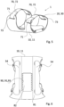
- the design is divided into a cuff base 10 in form of a lower shell 11 and a fixation element 20, which can be a cuff top 30 in form of an upper shell 31, see fig. 1 , or a strap system 70, see fig. 3 .
- the shells 11, 31 can be separated as two distinct elements.
- the lower shell 11 can in this case be set radially to the axis of the arm.
- the upper shell 31 can then be coupled to the lower shell 11 to create a closed system around the forearm.
- the number of shells 11, 31 can be larger than two and rise to three, four or more, but that can be the case only if they can be linked in such a way that the user does not need to hold them all in position before tightening them together around their forearm.
- the second form fit means 52 can be disconnected from the lower shell 11 whenever it is desired.
- the second form fit means 52 acts as a hook.
- Each second form fit means 52 is provided at a lacing element 61 in form of a cable, which is connected with a lacing knob 62. By turning of the lacing knob 62, tension is generated in the lacing element, which causes the tightening of the lacing system 60.
- At least one first magnetic part 41 is positioned in the body of the lower shell 11, and at least one second magnetic part 42 is positioned in the second form fit means 52 at the lacing system.
- a common part at which a plurality of the second form fit means 52 are provided a corresponding number of second magnetic parts 42 is provided at this common part 54, too.
- the number of form fit means 51, 52 can vary, and the form fit means 51, 52 can be positioned at different positions, as shown in fig. 4 .
- the interlocking form fit means 51, 52 can also be integrated into the shells, in this case the shells must be deformed when the lacing system 60 is being operated.
- the embodiment of the cuff 1 comprising a strap system 70 is not restricted to the embodiment shown in fig. 5 .
- a further embodiment not shown here may comprise a hook-based closure, similar or equal to the common part 54 at which a plurality of the second form fit means 52 and/ or second magnetic parts 42 are provided and which is shown in fig. 1 .
- the second form fit means 52 approaches its position, thanks to the attracting magnetic force 43 of the magnetic parts 41, 42.
- the user can tighten the strap system 70 with one hand thereby achieving an adjusted tighter or looser fit of the cuff 1 on the arm.
- cushioning material 80 is applied in the cuff base 10.
- Another aspect of the design is its modularity.
- the system allows for the connection of different modules to best meet the needs of the users.
- the module 100 can be inserted into the lower shell 11 of the cuff 1.
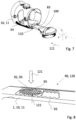
- an insertion element 110 of a module 100 can be directly inserted along a slide-in direction 111 into a retainer 82, which is provided in the cuff base 10 through an insertion opening 83 which in turn is arranged at the distal end of the cuff 1, shown in fig. 6 .
- the user has to press a button 95, shown in fig. 8 to 11 , and slide the insertion element 110 of the module 100 into the lower shell 11, while keeping the button 95 pressed.
- the button 95 is a special design on the insertion element 110 of the module 100, which slides into the lower shell 11. The user can then release the button 95 when the desired position is reached.
- the orthotic system comprising the cuff 1 and the module 100 further comprises a ratchet system 90.
- the ratchet system 90 comprises a first part 91 provided at the lower shell 11 of the cuff 1, as well as a second part 92 provided at the insertion element 110 of the module 100 and/ or at the button 95.
- Both components 91, 92 of the ratchet system 90 feature form elements 93, each having a shape like a tooth. In an embodiment, such tooth may have a rounded shape.
- the form elements 93 of the first part 91 and the second part 92 are complementary to each other in form and size.
- Positive locking 120 of these form elements 93 allows the transfer of loads along the y-axis, shown in fig. 7 .
- the module 100 can slide along the y-axis in the slide-in direction 111 parallel to an arm axis. Depending on the activity and intensity, different positions of the module 100 along the y-axis might be required. This allows for the same design to be used by users with different arm lengths.
- the distance between the area of interest of the module 100 and the insertion opening of the lower shell 11 as seen in fig. 7 can be adjusted by means of the ratchet system 90.
- the number of positions of the module 100 is determined by the number of form elements 93 on the first part 91 and the second part 92 of the ratchet system 90.
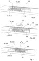
- Fig. 8 to 11 show a method for changing the position of the module with respect to the cuff 1.
- the button 95 is provided.
- a first part 91 of the ratchet system 90 is provided, comprising a plurality of form elements 93 in the shape of tooth, respectively.
- a second part 92 of the ratchet system 90 is provided, comprising also a plurality of form elements 93 in the shape of a tooth, respectively.
- the form elements 93 of the first part 91 and of the second part 92 of the ratchet system 90 are arranged in rows, respectively, and are complementary to each other in form and size.
- Fig. 8 shows a state in which the form elements 93 of the first part 91 and the second part 92 engage with each other.
- a positive locking 120 is established between the lower shell 11 and the insertion element 110.
- This engaged state is maintained by means of a force 122 acting on the insertion element 110 due to elasticity of the insertion element 110.
- the insertion element 110 When the insertion element 110 has been moved inward, by applying a moving force 123 on the button 95, the insertion element 110 can be moved parallel to the extension of the rows of form elements 93 of the first part 91 and of the second part 92 of the ratchet system 90. Thus, the position of the insertion element 110 and therefore the position of the module with respect to the cuff 1 can be adjusted, see fig. 10 .
Landscapes
- Health & Medical Sciences (AREA)
- Life Sciences & Earth Sciences (AREA)
- General Health & Medical Sciences (AREA)
- Transplantation (AREA)
- Engineering & Computer Science (AREA)
- Biomedical Technology (AREA)
- Heart & Thoracic Surgery (AREA)
- Orthopedic Medicine & Surgery (AREA)
- Vascular Medicine (AREA)
- Animal Behavior & Ethology (AREA)
- Veterinary Medicine (AREA)
- Public Health (AREA)
- Cardiology (AREA)
- Oral & Maxillofacial Surgery (AREA)
- Nursing (AREA)
- Orthopedics, Nursing, And Contraception (AREA)
- Prostheses (AREA)
Claims (12)
- Manschette (1), kombinierbar mit Zubehörteilen, zum Ausbilden eines Orthesesystems, umfassend eine Manschettenbasis (10) in Form einer unteren Schale (11) und ein Befestigungselement (20), das mit der unteren Schale (11) zu einer Hülle kombiniert werden kann oder kombiniert ist, die durch direkte oder indirekte Verschränkung an einer Gliedmaße angebracht werden kann, wobei die untere Schale (11) und das Befestigungselement (20) ein System bereitstellen, das durch Reduzieren eines von der unteren Schale (11) und dem Befestigungselement (20) ausgebildeten Umfangs um die Gliedmaße herum festgezogen werden kann, sodass eine Verlagerung der Belastung von einem Zubehörteil auf die Gliedmaße ermöglicht wird,
wobei die untere Schale (11) wenigstens ein erstes Formschlussmittel (51) umfasst und das Befestigungselement (20) wenigstens ein zweites Formschlussmittel (52) umfasst, wobei beide Formschlussmittel (51,52) dazu angepasst sind, eine Formschlussverbindung (50) zu realisieren, dadurch gekennzeichnet, dass die Verschränkung zwischen der unteren Schale und dem Befestigungselement eine magnetische Verbindung umfasst, wobei in einem Körper der unteren Schale wenigstens ein erstes magnetisches Teil bereitgestellt wird und in oder an dem Befestigungselement wenigstens ein zweites magnetisches Teil bereitgestellt wird, sodass das Befestigungselement mittels einer anziehenden Magnetkraft zwischen beiden magnetischen Teilen auf eine Seite des Körpers der unteren Schale bewegt werden kann oder wird oder an einer Seite des Körpers der unteren Schale gehalten werden kann; und dadurch, dass die Formschlussverbindung (50) einen Unterschnitt bereitstellt, um ein Lösen der Formschlussverbindung (50) zu verhindern, wenn sie einer Kraft unterliegt, die im Wesentlichen senkrecht zu einer Einführrichtung (53) der Formschlussverbindung (50) ist. - Manschette nach Anspruch 1, wobei das Befestigungselement (20) eine obere Schale (31) ist.
- Manschette nach Anspruch 2, wobei die Manschette (1) wenigstens ein Verschränkungselement in Form wenigstens eines Schnürelements (61) bereitstellt, das mechanisch mit beiden Schalen (11,31) verbunden wird, wenn das Verschränkungselement verschränkt wird, wobei das Schnürelement (61) so angepasst ist, dass bei Verkürzung einer effektiven Länge des Schnürelements (61) ein Abstand zwischen den zwei Schalen (11,31) reduziert wird.
- Manschette nach Anspruch 3, wobei das Schnürelement (61) eines der zweiten magnetischen Teile (42) und/oder eines der zweiten Formschlussmittel (52) umfasst.
- Manschette nach mindestens einem der vorangehenden Ansprüche, wobei das Befestigungselement (20) ein Riemensystem (70) ist.
- Manschette nach Anspruch 5, wobei das Riemensystem (70) wenigstens eines der zweiten magnetischen Teile (42) und/oder eines der zweiten Formschlussmittel (52) umfasst.
- Manschette nach mindestens einem der Ansprüche 5 und 6, wobei wenigstens ein Riemen (71) des Riemensystems (70) einen Klettverschluss (72) umfasst.
- Orthesesystem, das Folgendes umfasst: eine Manschette (1) nach wenigstens einem der Ansprüche 1-7 und ein Modul (100), das mechanisch mit der Manschette (1) verbunden ist oder verbindbar ist, wobei die Manschette (1) einen ersten Teil (91) eines Ratschensystems (90) umfasst und das Modul (100) einen zweiten Teil (92) des Ratschensystems (90) umfasst, wobei der erste Teil (91) und der zweite Teil (92) jeweils ein Formelement (93) aufweisen, das in Form und Größe komplementär ist.
- Orthesesystem nach Anspruch 8, wobei eines der Elemente der Manschette (1) und des Moduls (100) eine mit einem des ersten Teils (91) oder des zweiten Teils (92) des Ratschensystems versehene Halterung (82) umfasst und das jeweils andere Element der Manschette (1) und des Moduls (100) ein Einführelement (110) zum Positionieren in der Halterung (82) umfasst, wobei das Einführelement (110) mit dem jeweils anderen Teil des ersten Teils (91) oder des zweiten Teils (92) des Ratschensystems versehen ist und dazu ausgestaltet ist, entlang einer Einschubrichtung (111) in die Halterung (82) gepresst zu werden und den ersten Teil (91) und den zweiten Teil (92) aufgrund einer Kraftausübung (122) in eine positive Arretierung (120) zu bringen.
- Orthesesystem nach Anspruch 9, wobei die Kraftausübung (122) durch ein elastisches Verhalten des Einführelements (110) realisiert wird, das entsprechend den ersten Teil (91) oder den zweiten Teil (92) des Ratschensystems entsprechend in die Richtung des ersten Teils (91) oder des zweiten Teils (92) an der Halterung presst, um die positive Arretierung (120) zu erzeugen, wobei der E-Modul des Einführelements zwischen 0,5 GPa und 7 GPa liegt.
- Orthesesystem nach Anspruch 9, wobei das Einführelement (110) so angepasst ist, dass manuell gegen das Einführelement (110) gepresst und es damit durch eine Presskraft von wenigstens 3 N bewegt werden kann, sodass sich der erste Teil (91) oder der zweite Teil (92) des Ratschensystems aus der an der Halterung bereitgestellten positiven Arretierung (120) entsprechend mit dem ersten Teil (91) oder dem zweiten Teil (92) löst.
- Orthesesystem nach mindestens einem der Ansprüche 9 bis 11, wobei eine entsprechende Mehrzahl erster Teile (91) oder zweiter Teile (92) in Reihen angeordnet sind, sodass die positive Arretierung (120) an verschiedenen Positionen entlang der Einschubrichtung (111) umgesetzt werden kann.
Applications Claiming Priority (1)
| Application Number | Priority Date | Filing Date | Title |
|---|---|---|---|
| EP23160455 | 2023-03-07 |
Publications (3)
| Publication Number | Publication Date |
|---|---|
| EP4427709A1 EP4427709A1 (de) | 2024-09-11 |
| EP4427709C0 EP4427709C0 (de) | 2025-06-04 |
| EP4427709B1 true EP4427709B1 (de) | 2025-06-04 |
Family
ID=85511095
Family Applications (3)
| Application Number | Title | Priority Date | Filing Date |
|---|---|---|---|
| EP24162105.1A Pending EP4427710A1 (de) | 2023-03-07 | 2024-03-07 | Ratschensystem und orthesensystem |
| EP24162063.2A Pending EP4427713A1 (de) | 2023-03-07 | 2024-03-07 | Vorrichtung zur herstellung einer formschlüssigen und/oder kraftschlüssigen verbindung mit einem objekt sowie orthesensystem |
| EP24162058.2A Active EP4427709B1 (de) | 2023-03-07 | 2024-03-07 | Manschette und orthesensystem |
Family Applications Before (2)
| Application Number | Title | Priority Date | Filing Date |
|---|---|---|---|
| EP24162105.1A Pending EP4427710A1 (de) | 2023-03-07 | 2024-03-07 | Ratschensystem und orthesensystem |
| EP24162063.2A Pending EP4427713A1 (de) | 2023-03-07 | 2024-03-07 | Vorrichtung zur herstellung einer formschlüssigen und/oder kraftschlüssigen verbindung mit einem objekt sowie orthesensystem |
Country Status (1)
| Country | Link |
|---|---|
| EP (3) | EP4427710A1 (de) |
Family Cites Families (8)
| Publication number | Priority date | Publication date | Assignee | Title |
|---|---|---|---|---|
| US3942194A (en) * | 1974-08-30 | 1976-03-09 | Sybil Betty Anna Winter | Prosthetic device for handicapped persons |
| US6575926B2 (en) * | 2000-12-15 | 2003-06-10 | Bonutti 2003 Trust-A | Myofascial strap |
| US8231560B2 (en) * | 2004-12-22 | 2012-07-31 | Ossur Hf | Orthotic device and method for securing the same |
| US9757266B2 (en) * | 2010-06-01 | 2017-09-12 | Saebo, Inc. | Orthotic device |
| KR101895140B1 (ko) * | 2013-11-18 | 2018-09-04 | 보아 테크놀러지, 인크. | 보철 및 장구의 자동 폐쇄를 제공하기 위한 방법 및 장치 |
| DE102016108046B4 (de) * | 2016-04-29 | 2017-11-30 | Otto Bock Healthcare Products Gmbh | Prothesenschaftsystem sowie Prothesenschaft und Liner |
| EP3579793B1 (de) * | 2017-02-13 | 2021-03-31 | Össur Iceland EHF | Orthopädische vorrichtung |
| US9956093B1 (en) * | 2017-03-31 | 2018-05-01 | Warren Harris | Prosthetic limb cover |
-
2024
- 2024-03-07 EP EP24162105.1A patent/EP4427710A1/de active Pending
- 2024-03-07 EP EP24162063.2A patent/EP4427713A1/de active Pending
- 2024-03-07 EP EP24162058.2A patent/EP4427709B1/de active Active
Also Published As
| Publication number | Publication date |
|---|---|
| EP4427710A1 (de) | 2024-09-11 |
| EP4427709C0 (de) | 2025-06-04 |
| EP4427713A1 (de) | 2024-09-11 |
| EP4427709A1 (de) | 2024-09-11 |
Similar Documents
| Publication | Publication Date | Title |
|---|---|---|
| US20230320885A1 (en) | Self-Donning Powered Orthotic Device | |
| US20220110815A1 (en) | Rope-driven soft hand function rehabilitation device | |
| CN107708621B (zh) | 具有卡扣合套和锁扣机构的矫正装置 | |
| US6958048B2 (en) | Myofascial strap | |
| US6393615B1 (en) | Challenger glove for holding objects | |
| US6725865B2 (en) | Soft circular restraint apparatus and method | |
| US5322199A (en) | Apparatus for assisting a person in putting on a stocking | |
| WO2021188516A1 (en) | Exosuit having adjustable modular straps and bands | |
| EP4427709B1 (de) | Manschette und orthesensystem | |
| JP2009268896A (ja) | トレーニング器具 | |
| US20260060818A1 (en) | Cuff and orthotic system | |
| US6901932B2 (en) | Rapid deployment soft restraint apparatus and method | |
| EP1937192A1 (de) | Orthose | |
| US20260060820A1 (en) | Ratchet system and orthotic system | |
| EP2802391B1 (de) | Handriemen für einen skistock oder dergleichen | |
| US20060108756A1 (en) | Hands-free vehicle control device | |
| EP4474022A1 (de) | Handrehabilitationsvorrichtung | |
| US20260060829A1 (en) | Device for establishing a form-fitting and/or force-fitting connection to an object, and orthotic system | |
| US20020092530A1 (en) | Rapid deployment soft restraint apparatus and method | |
| US20030066535A1 (en) | Multi-point soft restraint apparatus and method | |
| US20210401612A1 (en) | Leg strap assembly for a urine bag | |
| US20100004106A1 (en) | Article of manufacture for assisting a user to engage a handle | |
| US20020151832A1 (en) | Composite finger flexion glove | |
| US20260060833A1 (en) | Multi-Functional Body Wrap and Sling Support Device | |
| US20060167392A1 (en) | Adjustable leg sling |
Legal Events
| Date | Code | Title | Description |
|---|---|---|---|
| PUAI | Public reference made under article 153(3) epc to a published international application that has entered the european phase |
Free format text: ORIGINAL CODE: 0009012 |
|
| STAA | Information on the status of an ep patent application or granted ep patent |
Free format text: STATUS: THE APPLICATION HAS BEEN PUBLISHED |
|
| AK | Designated contracting states |
Kind code of ref document: A1 Designated state(s): AL AT BE BG CH CY CZ DE DK EE ES FI FR GB GR HR HU IE IS IT LI LT LU LV MC ME MK MT NL NO PL PT RO RS SE SI SK SM TR |
|
| STAA | Information on the status of an ep patent application or granted ep patent |
Free format text: STATUS: REQUEST FOR EXAMINATION WAS MADE |
|
| 17P | Request for examination filed |
Effective date: 20241120 |
|
| RBV | Designated contracting states (corrected) |
Designated state(s): AL AT BE BG CH CY CZ DE DK EE ES FI FR GB GR HR HU IE IS IT LI LT LU LV MC ME MK MT NL NO PL PT RO RS SE SI SK SM TR |
|
| GRAP | Despatch of communication of intention to grant a patent |
Free format text: ORIGINAL CODE: EPIDOSNIGR1 |
|
| STAA | Information on the status of an ep patent application or granted ep patent |
Free format text: STATUS: GRANT OF PATENT IS INTENDED |
|
| INTG | Intention to grant announced |
Effective date: 20250227 |
|
| GRAS | Grant fee paid |
Free format text: ORIGINAL CODE: EPIDOSNIGR3 |
|
| GRAA | (expected) grant |
Free format text: ORIGINAL CODE: 0009210 |
|
| STAA | Information on the status of an ep patent application or granted ep patent |
Free format text: STATUS: THE PATENT HAS BEEN GRANTED |
|
| AK | Designated contracting states |
Kind code of ref document: B1 Designated state(s): AL AT BE BG CH CY CZ DE DK EE ES FI FR GB GR HR HU IE IS IT LI LT LU LV MC ME MK MT NL NO PL PT RO RS SE SI SK SM TR |
|
| REG | Reference to a national code |
Ref country code: GB Ref legal event code: FG4D |
|
| REG | Reference to a national code |
Ref country code: CH Ref legal event code: EP |
|
| REG | Reference to a national code |
Ref country code: DE Ref legal event code: R096 Ref document number: 602024000170 Country of ref document: DE |
|
| REG | Reference to a national code |
Ref country code: IE Ref legal event code: FG4D |
|
| U01 | Request for unitary effect filed |
Effective date: 20250704 |
|
| U07 | Unitary effect registered |
Designated state(s): AT BE BG DE DK EE FI FR IT LT LU LV MT NL PT RO SE SI Effective date: 20250716 |
|
| PG25 | Lapsed in a contracting state [announced via postgrant information from national office to epo] |
Ref country code: ES Free format text: LAPSE BECAUSE OF FAILURE TO SUBMIT A TRANSLATION OF THE DESCRIPTION OR TO PAY THE FEE WITHIN THE PRESCRIBED TIME-LIMIT Effective date: 20250604 |
|
| PG25 | Lapsed in a contracting state [announced via postgrant information from national office to epo] |
Ref country code: NO Free format text: LAPSE BECAUSE OF FAILURE TO SUBMIT A TRANSLATION OF THE DESCRIPTION OR TO PAY THE FEE WITHIN THE PRESCRIBED TIME-LIMIT Effective date: 20250904 Ref country code: GR Free format text: LAPSE BECAUSE OF FAILURE TO SUBMIT A TRANSLATION OF THE DESCRIPTION OR TO PAY THE FEE WITHIN THE PRESCRIBED TIME-LIMIT Effective date: 20250905 |
|
| PG25 | Lapsed in a contracting state [announced via postgrant information from national office to epo] |
Ref country code: PL Free format text: LAPSE BECAUSE OF FAILURE TO SUBMIT A TRANSLATION OF THE DESCRIPTION OR TO PAY THE FEE WITHIN THE PRESCRIBED TIME-LIMIT Effective date: 20250604 |
|
| PG25 | Lapsed in a contracting state [announced via postgrant information from national office to epo] |
Ref country code: HR Free format text: LAPSE BECAUSE OF FAILURE TO SUBMIT A TRANSLATION OF THE DESCRIPTION OR TO PAY THE FEE WITHIN THE PRESCRIBED TIME-LIMIT Effective date: 20250604 |
|
| PG25 | Lapsed in a contracting state [announced via postgrant information from national office to epo] |
Ref country code: RS Free format text: LAPSE BECAUSE OF FAILURE TO SUBMIT A TRANSLATION OF THE DESCRIPTION OR TO PAY THE FEE WITHIN THE PRESCRIBED TIME-LIMIT Effective date: 20250904 |
|
| PG25 | Lapsed in a contracting state [announced via postgrant information from national office to epo] |
Ref country code: IS Free format text: LAPSE BECAUSE OF FAILURE TO SUBMIT A TRANSLATION OF THE DESCRIPTION OR TO PAY THE FEE WITHIN THE PRESCRIBED TIME-LIMIT Effective date: 20251004 |
|
| PG25 | Lapsed in a contracting state [announced via postgrant information from national office to epo] |
Ref country code: SM Free format text: LAPSE BECAUSE OF FAILURE TO SUBMIT A TRANSLATION OF THE DESCRIPTION OR TO PAY THE FEE WITHIN THE PRESCRIBED TIME-LIMIT Effective date: 20250604 |
|
| PG25 | Lapsed in a contracting state [announced via postgrant information from national office to epo] |
Ref country code: CZ Free format text: LAPSE BECAUSE OF FAILURE TO SUBMIT A TRANSLATION OF THE DESCRIPTION OR TO PAY THE FEE WITHIN THE PRESCRIBED TIME-LIMIT Effective date: 20250604 |
|
| PG25 | Lapsed in a contracting state [announced via postgrant information from national office to epo] |
Ref country code: SK Free format text: LAPSE BECAUSE OF FAILURE TO SUBMIT A TRANSLATION OF THE DESCRIPTION OR TO PAY THE FEE WITHIN THE PRESCRIBED TIME-LIMIT Effective date: 20250604 |
|
| PLBE | No opposition filed within time limit |
Free format text: ORIGINAL CODE: 0009261 |
|
| STAA | Information on the status of an ep patent application or granted ep patent |
Free format text: STATUS: NO OPPOSITION FILED WITHIN TIME LIMIT |
|
| REG | Reference to a national code |
Ref country code: CH Ref legal event code: L10 Free format text: ST27 STATUS EVENT CODE: U-0-0-L10-L00 (AS PROVIDED BY THE NATIONAL OFFICE) Effective date: 20260416 |