EP4423455B1 - Deflektometriemessverfahren - Google Patents
Deflektometriemessverfahren Download PDFInfo
- Publication number
- EP4423455B1 EP4423455B1 EP22840241.8A EP22840241A EP4423455B1 EP 4423455 B1 EP4423455 B1 EP 4423455B1 EP 22840241 A EP22840241 A EP 22840241A EP 4423455 B1 EP4423455 B1 EP 4423455B1
- Authority
- EP
- European Patent Office
- Prior art keywords
- camera
- display
- deflectometer
- measurement
- stage
- Prior art date
- Legal status (The legal status is an assumption and is not a legal conclusion. Google has not performed a legal analysis and makes no representation as to the accuracy of the status listed.)
- Active
Links
Images



Classifications
-
- G—PHYSICS
- G01—MEASURING; TESTING
- G01B—MEASURING LENGTH, THICKNESS OR SIMILAR LINEAR DIMENSIONS; MEASURING ANGLES; MEASURING AREAS; MEASURING IRREGULARITIES OF SURFACES OR CONTOURS
- G01B11/00—Measuring arrangements characterised by the use of optical techniques
- G01B11/24—Measuring arrangements characterised by the use of optical techniques for measuring contours or curvatures
- G01B11/25—Measuring arrangements characterised by the use of optical techniques for measuring contours or curvatures by projecting a pattern, e.g. one or more lines, moiré fringes on the object
- G01B11/2518—Projection by scanning of the object
-
- G—PHYSICS
- G01—MEASURING; TESTING
- G01B—MEASURING LENGTH, THICKNESS OR SIMILAR LINEAR DIMENSIONS; MEASURING ANGLES; MEASURING AREAS; MEASURING IRREGULARITIES OF SURFACES OR CONTOURS
- G01B11/00—Measuring arrangements characterised by the use of optical techniques
- G01B11/24—Measuring arrangements characterised by the use of optical techniques for measuring contours or curvatures
- G01B11/25—Measuring arrangements characterised by the use of optical techniques for measuring contours or curvatures by projecting a pattern, e.g. one or more lines, moiré fringes on the object
- G01B11/2504—Calibration devices
-
- G—PHYSICS
- G01—MEASURING; TESTING
- G01B—MEASURING LENGTH, THICKNESS OR SIMILAR LINEAR DIMENSIONS; MEASURING ANGLES; MEASURING AREAS; MEASURING IRREGULARITIES OF SURFACES OR CONTOURS
- G01B5/00—Measuring arrangements characterised by the use of mechanical techniques
- G01B5/0002—Arrangements for supporting, fixing or guiding the measuring instrument or the object to be measured
- G01B5/0004—Supports
-
- G—PHYSICS
- G01—MEASURING; TESTING
- G01N—INVESTIGATING OR ANALYSING MATERIALS BY DETERMINING THEIR CHEMICAL OR PHYSICAL PROPERTIES
- G01N21/00—Investigating or analysing materials by the use of optical means, i.e. using sub-millimetre waves, infrared, visible or ultraviolet light
- G01N21/84—Systems specially adapted for particular applications
- G01N21/88—Investigating the presence of flaws or contamination
- G01N21/8806—Specially adapted optical and illumination features
-
- G—PHYSICS
- G01—MEASURING; TESTING
- G01N—INVESTIGATING OR ANALYSING MATERIALS BY DETERMINING THEIR CHEMICAL OR PHYSICAL PROPERTIES
- G01N21/00—Investigating or analysing materials by the use of optical means, i.e. using sub-millimetre waves, infrared, visible or ultraviolet light
- G01N21/84—Systems specially adapted for particular applications
- G01N21/88—Investigating the presence of flaws or contamination
- G01N21/8851—Scan or image signal processing specially adapted therefor, e.g. for scan signal adjustment, for detecting different kinds of defects, for compensating for structures, markings, edges
-
- G—PHYSICS
- G01—MEASURING; TESTING
- G01N—INVESTIGATING OR ANALYSING MATERIALS BY DETERMINING THEIR CHEMICAL OR PHYSICAL PROPERTIES
- G01N21/00—Investigating or analysing materials by the use of optical means, i.e. using sub-millimetre waves, infrared, visible or ultraviolet light
- G01N21/84—Systems specially adapted for particular applications
- G01N21/88—Investigating the presence of flaws or contamination
- G01N21/8806—Specially adapted optical and illumination features
- G01N2021/8829—Shadow projection or structured background, e.g. for deflectometry
Definitions
- the invention relates to the technical field of optical measuring instruments, and in particular to the field of deflectometers.
- the disadvantage of this method is that it does not allow to measure the shape of the object as such, but only the defects of the shape of the object. Indeed, the slopes of the surface, which induce a deformation of the projected fringes, are only quantitatively measurable if the shape of the surface is already known.
- the state of the art consists in considering that the object is approximately flat to estimate the slopes. Furthermore, the calculation of a shape from the slopes requires a calculation step by integration, which depends on an arbitrary constant. The evaluation of the slopes by this approximate method therefore provides an infinity of solutions for the shape of the object.
- the defects detected by this method can be of very small dimensions, often well below the micrometer, the measurement of the form is not quantitative. The measurement is only qualitative, since only the defects of the form are obtained.
- a known improvement of this method allows deflectometry to be used as a semi-quantitative measurement method.
- the measurement method uses additional input data, such as the distances between the camera, the object and the display, and the mutual orientation angles.
- the integration constant can then be determined, which allows the measurement to provide the shape of the object.
- the disadvantage is that measurements of the input data Additional measurements must be very careful for the process to provide satisfactory results, because these data must be transformed so that they are expressed in a single reference frame ("straightening"), which requires very precise determination of the position of the auxiliary measuring devices that are used.
- the measurement of shape defects is applied to a known nominal shape of the object to be measured, which makes it possible to obtain the real shape of the measured object.
- This method has the disadvantage of necessarily knowing the theoretical shape of the object to be measured in order to be able to obtain its real shape, which induces certain approximations in the quality of the measurement.
- Interferometry is another measurement method that allows to obtain the shape of an object with an uncertainty much lower than a micrometer, and is the reference method for measuring the shape quality of optical mirrors.
- an interferometer is an expensive device, very sensitive to vibrations and requires additional elements for measuring shapes other than planes or spheres. These elements are also very expensive most of the time. They can be custom-made compensation parts, commonly called “nulls", or computer-generated holograms.
- Another optical measurement method is stereo-deflectometry, in which a camera must acquire images of the object to be measured at different angular configurations. This method has the disadvantage of restricting the field measurable by the camera.
- Such a method is described in the documents US2005238237A1 And “Three-dimensional shape measurement of aspheric refractive optics by pattern transmission photogrammetry”, Marcus PETZ et al, Proc. SPIE 5144, DOI10.1117/12.500601 .
- a final method is measurement using a three-dimensional measuring machine, which performs spatial measurements using a probe at many points on the object to be measured.
- These machines are on the one hand expensive, and on the other hand very slow, because the spatial resolution of the measured shape is directly related to the number of measured points.
- Such a machine also operates in a regulated environment, particularly in terms of temperature, so that the measurement is correct.
- the aim of the invention is to overcome the drawbacks of the prior art by proposing a simple, inexpensive measuring method for obtaining the shape of an object with a quality close to the interferometry methods of the prior art.
- Another aim of the invention is to design a measuring device configured for the implementation of such a method, the device also having to be simple to use and inexpensive.
- the method allows to obtain the shape of the object, and not only its shape defects.
- the method does not use additional input data. It is therefore possible to obtain the measurement of the object from the object alone: the method is simplified and approximation errors are therefore avoided.
- the process uses the reflection of the fringes, and therefore the slopes of the shape to be measured, the uncertainty in the measurement is comparable to that of a measurement obtained by interferometry.
- the method comprises a step of calibrating the deflectometer by successive acquisitions of the fringe images in at least two configurations, and preferably at least three, of an optical system defined by the display positioned directly facing the camera.
- This calibration mode is simple and makes it possible to guarantee the reliability and performance of the method.
- the calibration involving only the display and the camera, makes it possible to correctly identify the trajectory of each incident ray of the camera and the real shape of the display, for the purpose of subsequent measurements.
- an additional step is necessary. It consists of moving the camera so that it is no longer aligned with the display, and arranging a reference mirror so as to reflect the projections of the display towards the camera.
- the measurement of the reference mirror is previously obtained by another means such as an interferometer, and the calibration step includes an additional step consisting of measuring the reference mirror by means of the deflectometer, and comparing the measurement obtained by the deflectometer with the prior measurement.
- the camera is mounted on a frame with the capacity to move between at least two positions, so that the camera captures images according to at least two configurations of an optical system defined by the display, the object and the camera; and the measurement of the object is a calculation of its shape
- the computer program is configured to calculate the geometry of the object only from the images acquired by the camera in the at least two configurations, and the calculation is done by integrating the slopes measured in each configuration.
- the deflectometer integrates inexpensive components.
- Such a deflectometer does not require the use of additional input data, and is therefore simple to use: it is sufficient to place the object to be measured within the optical system defined by the display, the object and the camera to be able to carry out the measurement. There is no restrictive step of precise positioning or alignment of the object or another element.
- an isostatic connection which means that this connection does not create any deformation of the mechanical structures involved, which would be a source of measurement errors.
- an isostatic mounting can be less expensive than precision mechanical systems, such as a precision screw.
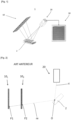
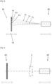
- This calibration step makes it possible to perfectly know the shape of the display and the optical paths of the incident rays (ri) to the camera (20), coming from the display (10), in each of the configurations. That is to say that from each pixel of the display, the trajectory of the incident ray (ri) connecting it to the camera (20) is determined. Three rays (ri 1 , ri 2 , ri 3 ) corresponding to three pixels (P1, P2, P3) are shown.
- This calibration step makes it possible to obtain the equations of all incident rays (ri) at the camera (20) in the frame of reference of the optical system, with a lateral accuracy of the order of a micrometer, and angular accuracy of the order of a microradian.
- the reference mirror (3) is previously known. That is to say, its exact shape has been measured, for example by interferometry or using another already calibrated deflectometer.
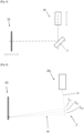
- the affine transformation corresponding to the displacement of the camera (20) relative to the display (10) can be determined from acquisitions of fringe images of the display (10) when the reference mirror (3) is in at least three arbitrary different positions allowing the camera (20) to have these fringes in its field. There is no constraint on the quality or repeatability of the positioning of the reference mirror (20) in this step. This is a loose positioning.
- the reference mirror (3) is then removed, and the object (2) is positioned such that the camera (20) has the fringes seen by reflection in its field.
- the camera (20) acquires the reflected fringes a first time, in a first configuration where the camera (20) is in a first position (20 1 ).
- the fringe display is a predetermined pattern and the incident rays (ri) at the camera (20) have all been identified during the calibration step, we knows, for each incident ray (ri), its starting point from the display (10). The unknown is the shape and position of the object (2) which allowed its reflection in the direction of the camera (20).
- the computer program (30) is programmed to perform the calculations to identify the possible solutions of the shape and position of the object (2).
- an infinite number of solutions are possible.
- the camera (20) has been moved and is in a second position (20 2 ). A new acquisition is made in this second configuration of the optical system.
- the last step of the method according to the invention is to compare the sets of solutions obtained in each configuration, in order to determine which is the only solution which is common to each configuration: this solution corresponds to the real shape and position of the object (2) to be measured.
- the invention also relates to a deflectometer (1) designed to implement the method described above.
- such a deflectometer (1) comprises a display (10) and a camera (20). At least the camera (20), and preferably the camera and the display, is mounted movably relative to a frame (40). At least the camera (20) must be movable so that the optical system can be mounted in two different configurations.
- the display (10) and the camera (20) are mobile makes it possible to multiply the number of different configurations, and to adapt more easily to different shapes of objects (2) to be measured. It is thus possible to measure concave mirrors and convex mirrors with the same deflectometer (1).
- the frame (40) is preferably in two parts so as to be able to easily pass from a position where the display (10) and the camera (20) are aligned for the calibration step, to a remote position where the display (10) and the camera (20) are remote for the step of measuring a reflective object (2).
- the mobility of the display (10) and/or the camera (20) is an axial translation along an optical axis of the camera (20).
- the measurement carried out is therefore a coaxial deflectometry.
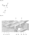
- this mobility is obtained by means of a two-stage system: a first stage (41) is mounted in sliding connection relative to the frame (40).
- This sliding connection can be of any suitable type, an economical means is the use of profiles cooperating with rollers (411) of complementary shape.
- this mobility is motorized, for example by means of a motor (413) driving a system of pulleys and belts or a worm screw.
- connection between the first stage (41) and the second stage (42) is not a slide connection in the strict sense, because the positioning of the second stage (42) must be free in relation to the first stage (41). It is therefore a kinematic connection. incomplete, with a lot of play.
- the second stage (42) is in isostatic connection with the frame (40) so that the indexed position is always repeatable, identical to the nearest micrometer each time the second stage (42) passes from the free position to the indexed position. If the first stage (41) prevents the second stage (42) from positioning itself without constraint on the frame (40), then the configuration of the optical system is not exactly repeatable and the measurement will be hampered.
- Moving the display and/or camera in an axial translation makes it possible to measure objects of larger dimensions than if the measurement of the object were done at different angles (principle of stereo-deflectometry).
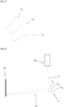
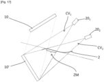
- a camera (20) is moved in two positions.
- the measurable area (ZM) is at the intersection of the fields of view (CV 1 , CV 2 ) of each camera (20 1 , 20 2 ).
- a mirror display (10') is shown, which is the image of the display (10) as seen by the camera (20). This is a plane symmetry of the display (10) with respect to a plane locally tangent to the object (2).
- the area must be measured according to several angular configurations.
- the measurable area (ZM) is of restricted area.
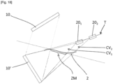
- the stereoscopic effect therefore the sensitivity of the measurement, increases with the angular deviation of the observations, but concomitantly restricts the measurable area (ZM). This is a serious drawback of stereo-deflectometry, which is overcome by the illustrated embodiment figure 18 .
- the camera (20) is now moved along an axis translation (T), without changing the point of view of the camera (20). It can be seen that the measurable area (ZM), at the intersection of the fields of vision (CV 1 , CV 2 ) of each camera (20 1 , 20 2 ), is much larger.
- the method according to which the movement trajectory of the display and/or the camera is an axial translation therefore makes it possible to measure objects of larger dimensions.
- the second stage (42) may comprise three spherical-shaped elements (43), such as domed-head pins or screws, bearing by simple gravity against internal faces of Vs (45), i.e. “V”-shaped shims, which are arranged on the frame (40).
- Vs (45) For the Boys connection to work, the Vs (45) must not be parallel to each other, and preferably the axes of the Vs (45) are concurrent at a central point of the connection.
- the spherical-shaped elements (43) may be positioned on the first stage (41) and the Vs (45) on the second stage (42).
- Vs (45) allows for greater latitude in position deviation when docking the second stage (42) on the frame (40), which simplifies the design of the clearance slide connection connecting the second stage (42) to the first stage (41).
- the free connection of the preferred mode takes the form of pins (414) fixed on the first stage (41), and inserted into oblong holes (421) of the second stage (42). There is a significant clearance between the pins (414) and the holes (421), between 1 mm and 5 mm.
- the oblong holes (421) are oriented vertically, and their length is sufficient to be able to disengage the Vs (45) or the spherical stops (44) from the pins (43), thus separating the isostatic connection from the preferred mode, since it is normally maintained by gravity.
- the transition from the indexed position to the free position is preferably motorized, and can be obtained by means of a jack or an eccentric mounted on the first stage (41), allowing the second stage (42) to be lifted.
- the kinematics and the motorization of the retraction between the free position and the indexed position can be adapted if the isostatic connection is of a different construction, for example of the “point line plane” type.
- the frame (40) comprises several cradles (B1-B5) each configured to isostatically receive the second stage (42).
- each cradle (B1-B5) therefore comprises three pins (43).
- the display (10) is mobile between several cradles (B1-B5) distributed over a length of approximately 2 m.
- the significant length makes it possible to obtain the trajectory of the incident rays (ri) with significant precision.
- the camera (20) is mobile between several cradles distributed over a length of approximately 25 cm. This length is sufficient for the configurations used during the measurement step to be sufficiently different, and for the method to determine the shape of the object (2) with the expected precision. In addition, this length is sufficiently short for the part of the frame (40) that carries the camera (20) to be compact, which makes it easier to switch from the aligned position used for calibration to the offset position used for measuring a reflective object (2).
- any camera settings (20), such as a diaphragm or lens aperture, are motorized and connected to the computer (30) and are also managed by the program.
- the automation of the deflectometer (1) is further improved.
- the method and the deflectometer (1) may be configured differently from the examples and illustrations given without departing from the scope of the invention, which is defined by the claims.
- the camera (20) is mobile between several configurations, in order to save on equipment.
- the camera (20) is lighter and less cumbersome to move than the display. In one embodiment, it is therefore only the camera (20) which is mobile.
- the technical characteristics of the various embodiments and variants mentioned above can be, in whole or in some cases, combined with each other.
- the method and the deflectometer (1) can be adapted in terms of cost, functionality and performance.
Landscapes
- Physics & Mathematics (AREA)
- General Physics & Mathematics (AREA)
- Engineering & Computer Science (AREA)
- Computer Vision & Pattern Recognition (AREA)
- Chemical & Material Sciences (AREA)
- Life Sciences & Earth Sciences (AREA)
- Health & Medical Sciences (AREA)
- Analytical Chemistry (AREA)
- Biochemistry (AREA)
- General Health & Medical Sciences (AREA)
- Immunology (AREA)
- Pathology (AREA)
- Signal Processing (AREA)
- Length Measuring Devices By Optical Means (AREA)
- Investigating Or Analysing Materials By Optical Means (AREA)
Claims (11)
- Verfahren zur Durchführung einer Messung an einem reflektierenden Objekt (2) oder einem transparenten Objekt (2) mittels eines Deflektometers (1), das umfasst:- eine Anzeige (10), die dynamische Streifen darstellt;- eine Kamera (20), die so konfiguriert ist, dass sie Bilder von den vom reflektierenden Objekt (2) reflektierten Streifen und/oder die Bilder von den durch das transparente Objekt (2) übertragenen Streifen aufnimmt;- einen Computer (30), der so konfiguriert ist, ein Programm auszuführen, um die Messung auf Basis der von der Kamera (20) aufgenommenen Bilder durchzuführen; wobei das Verfahren dadurch gekennzeichnet ist, dass es die folgenden Schritte umfasst:- sukzessive Aufnahme der von dem Objekt (2) reflektierten und/oder übertragenen Streifenbilder in mindestens zwei Konfigurationen eines optischen Systems, das durch die Anzeige (10), das Objekt (2) und die Kamera (20) definiert ist;- basierend auf den aufgenommenen Bildern das Programm ausführen und mögliche Lösungen für die Form des Objekts (2) und die Position des Objekts (2) innerhalb des optischen Systems, das durch die Anzeige (10), das Objekt (2) und die Kamera (20) definiert ist, in jeder der Konfigurationen berechnen;- eine endgültige Lösung für die Form und Position des Objekts (2) ermitteln, indem eine einzige Lösung identifiziert wird, die den zuvor berechneten möglichen Lösungen gemeinsam ist; dadurch gekennzeichnet, dass die Kamera (20) entlang einer optischen Achse der Kamera (20) zwischen sukzessiven Aufnahmen axial verschoben wird.
- Messverfahren nach Anspruch 1, dadurch gekennzeichnet, dass es einen Schritt zur Kalibrierung des Deflektometers (1) umfasst, indem die Bilder von Streifen sukzessive in mindestens zwei Konfigurationen eines optischen Systems aufgenommen werden, das durch die Anzeige (10), die sich direkt gegenüber der Kamera (20) befindet, definiert ist.
- Messverfahren nach Anspruch 2, dadurch gekennzeichnet, dass der Kalibrierschritt einen zusätzlichen Schritt umfasst, der darin besteht, die Anzeige (10) und/oder die Kamera (20) zu verschieben, sodass sie nicht mehr ausgerichtet sind, und einen Referenzspiegel (3) so zu platzieren, dass er die Projektionen der Anzeige (10) in Richtung der Kamera (20) reflektiert.
- Messverfahren nach Anspruch 3, dadurch gekennzeichnet, dass die Messung des Referenzspiegels (3) zuvor mit einem anderen Mittel, wie einem Interferometer, durchgeführt wurde, und der Kalibrierschritt einen zusätzlichen Schritt umfasst, der darin besteht, den Referenzspiegel (3) mit dem Deflektometer (1) zu vermessen, um dessen korrekte Funktion zu überprüfen, indem die mit dem Deflektometer (1) erhaltene Messung mit der vorherigen Messung verglichen wird.
- Deflektometer (1) zur Durchführung einer Messung an einem reflektierenden Objekt (2) oder einem transparenten Objekt (2), das umfasst:- eine Anzeige (10), die dynamische Streifen darstellt;- eine Kamera (20), die so konfiguriert ist, dass sie die Bilder von den vom reflektierenden Objekt (2) reflektierten Streifen und/oder die Bilder von den durch das transparente Objekt (2) übertragenen Streifen aufnimmt;- einen Computer (30), der so konfiguriert ist, ein Programm auszuführen, um die Messung auf Basis der von der Kamera (20) aufgenommenen Bilder durchzuführen; dadurch gekennzeichnet, dass die Kamera (20) auf einem Rahmen (40) montiert ist und axial entlang einer optischen Achse der Kamera (20) zwischen mindestens zwei Positionen verschoben werden kann, sodass die Kamera (20) Bilder entsprechend mindestens zwei Konfigurationen eines optischen Systems aufnimmt, das durch die Anzeige (10), das Objekt (2) und die Kamera (20) definiert ist; und dass die Messung des Objekts (2) eine Berechnung seiner Form ist, wobei das Computerprogramm so konfiguriert ist, die Geometrie des Objekts (2) ausschließlich auf der Grundlage der von der Kamera (20) in den mindestens zwei Konfigurationen aufgenommenen Bilder zu berechnen, und die Berechnung durch Integration der in jeder Konfiguration gemessenen Neigungen erfolgt; und dass die Kamera (20) durch eine isostatische Verbindung auf dem Rahmen (40) montiert ist.
- Deflektometer (1) nach Anspruch 5, dadurch gekennzeichnet, dass die Bewegung der Kamera (20) durch ein Zweistufensystem sichergestellt wird, das eine erste Stufe (41) umfasst, die relativ zum Rahmen (40) bewegt werden kann, und eine zweite Stufe (42) trägt, auf der die Kamera (20) befestigt ist; die zweite Stufe (42) ist zwischen:- einer freien Position, in der sie die Bewegung der ersten Stufe (41) relativ zum Rahmen (40) nicht behindert, und- einer indexierten Position, in der sie die Bewegung der ersten Stufe (41) behindert und isostatisch mit dem Rahmen (40) verbunden ist, zurückziehbar.
- Deflektometer (1) nach einem der Ansprüche 5 bis 6, dadurch gekennzeichnet, dass die isostatische Verbindung vom Typ Boys-Verbindung ist.
- Deflektometer (1) nach Anspruch 7, dadurch gekennzeichnet, dass die Boys-Verbindung durch drei kugelförmige Stifte (43) erreicht wird, die in einem Dreieck an einer unteren Fläche der zweiten Stufe (42) gegenüber dem Rahmen (40) positioniert sind, wobei jeder Stift an zwei Innenflächen eines gegenüber einer oberen Fläche des Rahmens (40) positionierten V (45) anliegt.
- Deflektometer (1) nach Anspruch 5, dadurch gekennzeichnet, dass die Anzeige (10) entlang einer geradlinigen Achse bewegt werden kann.
- Deflektometer (1) nach Anspruch 9, dadurch gekennzeichnet, dass die Bewegung der Anzeige (10) und/oder der Kamera (20) durch Folgendes sichergestellt wird:- eine motorisierte horizontale Gleitverbindung, die die Bewegung der ersten Stufe (41) relativ zum Rahmen (40) sicherstellt;- eine motorisierte vertikale Gleitverbindung, die es ermöglicht, die zweite Stufe (42) zwischen der freien Position und der indexierten Position zurückzuziehen, wobei die vertikale Gleitverbindung ein Spiel aufweist.
- Deflektometer (1) nach Anspruch 10, dadurch gekennzeichnet, dass die Motoren der horizontalen und vertikalen Gleitverbindungen mit dem Computer (30) verbunden sind, und das Computerprogramm so konfiguriert ist, dass die Motoren automatisch gesteuert werden, um die Anzeige (10) und/oder die Kamera (20) zwischen den Positionen zu bewegen.
Applications Claiming Priority (2)
| Application Number | Priority Date | Filing Date | Title |
|---|---|---|---|
| FR2112836A FR3130025B1 (fr) | 2021-12-02 | 2021-12-02 | procédé de mesure par déflectométrie |
| PCT/FR2022/052187 WO2023099836A1 (fr) | 2021-12-02 | 2022-11-28 | Procédé de mesure par déflectométrie |
Publications (3)
| Publication Number | Publication Date |
|---|---|
| EP4423455A1 EP4423455A1 (de) | 2024-09-04 |
| EP4423455B1 true EP4423455B1 (de) | 2025-01-29 |
| EP4423455C0 EP4423455C0 (de) | 2025-01-29 |
Family
ID=80999799
Family Applications (1)
| Application Number | Title | Priority Date | Filing Date |
|---|---|---|---|
| EP22840241.8A Active EP4423455B1 (de) | 2021-12-02 | 2022-11-28 | Deflektometriemessverfahren |
Country Status (7)
| Country | Link |
|---|---|
| US (1) | US20250035432A1 (de) |
| EP (1) | EP4423455B1 (de) |
| JP (1) | JP2024544771A (de) |
| KR (1) | KR20240116521A (de) |
| CN (1) | CN118679360A (de) |
| FR (1) | FR3130025B1 (de) |
| WO (1) | WO2023099836A1 (de) |
Family Cites Families (14)
| Publication number | Priority date | Publication date | Assignee | Title |
|---|---|---|---|---|
| EP1306646A4 (de) * | 2000-06-07 | 2006-08-16 | Citizen Watch Co Ltd | Verbandmusterprojektor mit einem flüssigkristallverband |
| DE10127304C5 (de) * | 2001-06-06 | 2007-07-19 | Technische Universität Carolo-Wilhelmina Zu Braunschweig | Verfahren und Vorrichtung zur Bestimmung der dreidimensionalen Kontur einer spiegelnden Oberfläche eines Objektes |
| DE602004006600T2 (de) * | 2004-03-18 | 2008-01-31 | Tesa Sa | Werkzeugwechselvorrichtung |
| EP1584946A3 (de) * | 2004-04-02 | 2006-03-22 | Omron Corporation | Verfahren zur Ausrichtung von optischen Sensoren |
| DE102004020419B3 (de) * | 2004-04-23 | 2005-10-20 | 3D Shape Gmbh | Verfahren und Vorrichtung zur Bestimmung der Form und der lokalen Oberflächennormalen spiegelnder Oberflächen |
| DE602004025215D1 (de) * | 2004-06-22 | 2010-03-11 | Tesa Sa | Tastsonde |
| EP1617172B1 (de) * | 2004-07-16 | 2007-12-26 | Tesa SA | Lenkbarer Taststift |
| DE602004011794T2 (de) * | 2004-12-01 | 2009-02-05 | Tesa Sa | Motorisierter und orientierbarer Messkopf |
| US7711182B2 (en) * | 2006-08-01 | 2010-05-04 | Mitsubishi Electric Research Laboratories, Inc. | Method and system for sensing 3D shapes of objects with specular and hybrid specular-diffuse surfaces |
| WO2008133650A2 (en) * | 2006-11-07 | 2008-11-06 | Rudolph Technologies, Inc. | Method and system for providing a high definition triangulation system |
| JP5843241B2 (ja) * | 2013-11-26 | 2016-01-13 | レーザーテック株式会社 | 検査装置、及び検査方法 |
| FR3058407B1 (fr) * | 2016-11-09 | 2020-11-06 | Excent France | Base mobile et procede de transport d'un equipement |
| JP2019082452A (ja) * | 2017-10-31 | 2019-05-30 | キヤノン株式会社 | 画像生成方法、画像生成装置、及びそれらを用いた欠陥判定方法 |
| JP7137345B2 (ja) * | 2018-04-20 | 2022-09-14 | 株式会社キーエンス | 形状測定装置、形状測定方法、形状測定プログラム及びコンピュータで読み取り可能な記録媒体並びに記録した機器 |
-
2021
- 2021-12-02 FR FR2112836A patent/FR3130025B1/fr active Active
-
2022
- 2022-11-28 EP EP22840241.8A patent/EP4423455B1/de active Active
- 2022-11-28 CN CN202280086152.0A patent/CN118679360A/zh active Pending
- 2022-11-28 JP JP2024533108A patent/JP2024544771A/ja active Pending
- 2022-11-28 KR KR1020247021973A patent/KR20240116521A/ko active Pending
- 2022-11-28 US US18/715,720 patent/US20250035432A1/en active Pending
- 2022-11-28 WO PCT/FR2022/052187 patent/WO2023099836A1/fr not_active Ceased
Also Published As
| Publication number | Publication date |
|---|---|
| EP4423455A1 (de) | 2024-09-04 |
| US20250035432A1 (en) | 2025-01-30 |
| EP4423455C0 (de) | 2025-01-29 |
| WO2023099836A1 (fr) | 2023-06-08 |
| FR3130025A1 (fr) | 2023-06-09 |
| JP2024544771A (ja) | 2024-12-04 |
| FR3130025B1 (fr) | 2024-03-08 |
| KR20240116521A (ko) | 2024-07-29 |
| CN118679360A (zh) | 2024-09-20 |
Similar Documents
| Publication | Publication Date | Title |
|---|---|---|
| Häusler et al. | Deflectometry vs. interferometry | |
| EP2369319B1 (de) | Verfahren und Vorrichtung zum Messen eines asphärischen Objekts | |
| EP3890922B1 (de) | System und verfahren zur messung des profils eines werkstücks | |
| EP3935341A1 (de) | Verfahren und vorrichtung zum messen von schnittstellen eines optischen elements | |
| CN103003662A (zh) | 用于测量被检表面的形状的测量方法、测量设备和光学元件的制造方法 | |
| Su et al. | Precision aspheric optics testing with SCOTS: a deflectometry approach | |
| FR2869408A1 (fr) | Procede et dispositif pour determiner la forme et les normales locales de surfaces reflechissantes | |
| JP2010281792A (ja) | 非球面体測定方法および装置 | |
| EP4466517B1 (de) | Verfahren und vorrichtung zur bestimmung geometrischer informationen über schnittstellen eines optischen elements | |
| JP7204428B2 (ja) | 偏心計測方法、レンズ製造方法、および偏心計測装置 | |
| WO2015071116A1 (fr) | Dispositif et methode de mise au point tridimensionnelle pour microscope | |
| KR20110065365A (ko) | 비구면체 측정 방법 및 장치 | |
| WO2012132930A1 (ja) | レンズ測定装置 | |
| EP3724725B1 (de) | Verfahren zur kalibrierung einer analysevorrichtung und zugehörige vorrichtung | |
| EP2478395A1 (de) | Ausrichtungsverfahren zur steuerung eines spiegels | |
| WO2023099836A1 (fr) | Procédé de mesure par déflectométrie | |
| Langehanenberg et al. | Automated measurement of centering errors and relative surface distances for the optimized assembly of micro-optics | |
| FR2980844A1 (fr) | Procede d'etalonnage d'une barre de mise a l'echelle | |
| FR3104699A1 (fr) | Système de contrôle d’au moins un composant d’un élément optique | |
| FR3154489A1 (fr) | Système et procédé de calibrage d’un profilomètre entrainé en rotation | |
| EP3835748B1 (de) | Kontrollsystem mindestens einer komponente eines optischen elements | |
| JP3599921B2 (ja) | 屈折率分布の測定方法及び装置 | |
| Quinten | Optical Surface Metrology: Methods | |
| TWI596325B (zh) | 決定物體或透明光學元件的資訊的方法與系統以及形成光學組件方法 | |
| Iturbide et al. | Fast, semi-automated geometric and functional characterization of miniaturized lenses using optical coherence tomography-based systems and wavefront sensors |
Legal Events
| Date | Code | Title | Description |
|---|---|---|---|
| STAA | Information on the status of an ep patent application or granted ep patent |
Free format text: STATUS: UNKNOWN |
|
| STAA | Information on the status of an ep patent application or granted ep patent |
Free format text: STATUS: THE INTERNATIONAL PUBLICATION HAS BEEN MADE |
|
| PUAI | Public reference made under article 153(3) epc to a published international application that has entered the european phase |
Free format text: ORIGINAL CODE: 0009012 |
|
| STAA | Information on the status of an ep patent application or granted ep patent |
Free format text: STATUS: REQUEST FOR EXAMINATION WAS MADE |
|
| 17P | Request for examination filed |
Effective date: 20240531 |
|
| AK | Designated contracting states |
Kind code of ref document: A1 Designated state(s): AL AT BE BG CH CY CZ DE DK EE ES FI FR GB GR HR HU IE IS IT LI LT LU LV MC ME MK MT NL NO PL PT RO RS SE SI SK SM TR |
|
| GRAP | Despatch of communication of intention to grant a patent |
Free format text: ORIGINAL CODE: EPIDOSNIGR1 |
|
| STAA | Information on the status of an ep patent application or granted ep patent |
Free format text: STATUS: GRANT OF PATENT IS INTENDED |
|
| INTG | Intention to grant announced |
Effective date: 20240917 |
|
| GRAS | Grant fee paid |
Free format text: ORIGINAL CODE: EPIDOSNIGR3 |
|
| GRAA | (expected) grant |
Free format text: ORIGINAL CODE: 0009210 |
|
| STAA | Information on the status of an ep patent application or granted ep patent |
Free format text: STATUS: THE PATENT HAS BEEN GRANTED |
|
| DAV | Request for validation of the european patent (deleted) | ||
| DAX | Request for extension of the european patent (deleted) | ||
| AK | Designated contracting states |
Kind code of ref document: B1 Designated state(s): AL AT BE BG CH CY CZ DE DK EE ES FI FR GB GR HR HU IE IS IT LI LT LU LV MC ME MK MT NL NO PL PT RO RS SE SI SK SM TR |
|
| REG | Reference to a national code |
Ref country code: GB Ref legal event code: FG4D Free format text: NOT ENGLISH |
|
| REG | Reference to a national code |
Ref country code: CH Ref legal event code: EP |
|
| REG | Reference to a national code |
Ref country code: DE Ref legal event code: R096 Ref document number: 602022010302 Country of ref document: DE |
|
| REG | Reference to a national code |
Ref country code: IE Ref legal event code: FG4D Free format text: LANGUAGE OF EP DOCUMENT: FRENCH |
|
| U01 | Request for unitary effect filed |
Effective date: 20250129 |
|
| U07 | Unitary effect registered |
Designated state(s): AT BE BG DE DK EE FI FR IT LT LU LV MT NL PT RO SE SI Effective date: 20250205 |
|
| PG25 | Lapsed in a contracting state [announced via postgrant information from national office to epo] |
Ref country code: RS Free format text: LAPSE BECAUSE OF FAILURE TO SUBMIT A TRANSLATION OF THE DESCRIPTION OR TO PAY THE FEE WITHIN THE PRESCRIBED TIME-LIMIT Effective date: 20250429 |
|
| PG25 | Lapsed in a contracting state [announced via postgrant information from national office to epo] |
Ref country code: PL Free format text: LAPSE BECAUSE OF FAILURE TO SUBMIT A TRANSLATION OF THE DESCRIPTION OR TO PAY THE FEE WITHIN THE PRESCRIBED TIME-LIMIT Effective date: 20250129 |
|
| PG25 | Lapsed in a contracting state [announced via postgrant information from national office to epo] |
Ref country code: ES Free format text: LAPSE BECAUSE OF FAILURE TO SUBMIT A TRANSLATION OF THE DESCRIPTION OR TO PAY THE FEE WITHIN THE PRESCRIBED TIME-LIMIT Effective date: 20250129 |
|
| PG25 | Lapsed in a contracting state [announced via postgrant information from national office to epo] |
Ref country code: NO Free format text: LAPSE BECAUSE OF FAILURE TO SUBMIT A TRANSLATION OF THE DESCRIPTION OR TO PAY THE FEE WITHIN THE PRESCRIBED TIME-LIMIT Effective date: 20250429 Ref country code: IS Free format text: LAPSE BECAUSE OF FAILURE TO SUBMIT A TRANSLATION OF THE DESCRIPTION OR TO PAY THE FEE WITHIN THE PRESCRIBED TIME-LIMIT Effective date: 20250529 |
|
| PG25 | Lapsed in a contracting state [announced via postgrant information from national office to epo] |
Ref country code: HR Free format text: LAPSE BECAUSE OF FAILURE TO SUBMIT A TRANSLATION OF THE DESCRIPTION OR TO PAY THE FEE WITHIN THE PRESCRIBED TIME-LIMIT Effective date: 20250129 |
|
| PG25 | Lapsed in a contracting state [announced via postgrant information from national office to epo] |
Ref country code: GR Free format text: LAPSE BECAUSE OF FAILURE TO SUBMIT A TRANSLATION OF THE DESCRIPTION OR TO PAY THE FEE WITHIN THE PRESCRIBED TIME-LIMIT Effective date: 20250430 |
|
| PG25 | Lapsed in a contracting state [announced via postgrant information from national office to epo] |
Ref country code: SM Free format text: LAPSE BECAUSE OF FAILURE TO SUBMIT A TRANSLATION OF THE DESCRIPTION OR TO PAY THE FEE WITHIN THE PRESCRIBED TIME-LIMIT Effective date: 20250129 |
|
| PG25 | Lapsed in a contracting state [announced via postgrant information from national office to epo] |
Ref country code: CZ Free format text: LAPSE BECAUSE OF FAILURE TO SUBMIT A TRANSLATION OF THE DESCRIPTION OR TO PAY THE FEE WITHIN THE PRESCRIBED TIME-LIMIT Effective date: 20250129 |
|
| PG25 | Lapsed in a contracting state [announced via postgrant information from national office to epo] |
Ref country code: SK Free format text: LAPSE BECAUSE OF FAILURE TO SUBMIT A TRANSLATION OF THE DESCRIPTION OR TO PAY THE FEE WITHIN THE PRESCRIBED TIME-LIMIT Effective date: 20250129 |
|
| PLBE | No opposition filed within time limit |
Free format text: ORIGINAL CODE: 0009261 |
|
| STAA | Information on the status of an ep patent application or granted ep patent |
Free format text: STATUS: NO OPPOSITION FILED WITHIN TIME LIMIT |
|
| REG | Reference to a national code |
Ref country code: CH Ref legal event code: L10 Free format text: ST27 STATUS EVENT CODE: U-0-0-L10-L00 (AS PROVIDED BY THE NATIONAL OFFICE) Effective date: 20251210 |
|
| REG | Reference to a national code |
Ref country code: CH Ref legal event code: U11 Free format text: ST27 STATUS EVENT CODE: U-0-0-U10-U11 (AS PROVIDED BY THE NATIONAL OFFICE) Effective date: 20251230 |
|
| 26N | No opposition filed |
Effective date: 20251030 |
|
| U20 | Renewal fee for the european patent with unitary effect paid |
Year of fee payment: 4 Effective date: 20251128 |
|
| PGFP | Annual fee paid to national office [announced via postgrant information from national office to epo] |
Ref country code: CH Payment date: 20251230 Year of fee payment: 4 |
|
| PG25 | Lapsed in a contracting state [announced via postgrant information from national office to epo] |
Ref country code: MC Free format text: LAPSE BECAUSE OF FAILURE TO SUBMIT A TRANSLATION OF THE DESCRIPTION OR TO PAY THE FEE WITHIN THE PRESCRIBED TIME-LIMIT Effective date: 20250129 |