EP4422972B1 - Steuerungsvorrichtung zur veränderung des anstellwinkels der blätter eines heckrotors für ein schwebfähiges flugzeug - Google Patents
Steuerungsvorrichtung zur veränderung des anstellwinkels der blätter eines heckrotors für ein schwebfähiges flugzeug Download PDFInfo
- Publication number
- EP4422972B1 EP4422972B1 EP22735037.8A EP22735037A EP4422972B1 EP 4422972 B1 EP4422972 B1 EP 4422972B1 EP 22735037 A EP22735037 A EP 22735037A EP 4422972 B1 EP4422972 B1 EP 4422972B1
- Authority
- EP
- European Patent Office
- Prior art keywords
- profile
- axis
- interfaces
- bushing
- control rod
- Prior art date
- Legal status (The legal status is an assumption and is not a legal conclusion. Google has not performed a legal analysis and makes no representation as to the accuracy of the status listed.)
- Active
Links
Images


Classifications
-
- B—PERFORMING OPERATIONS; TRANSPORTING
- B64—AIRCRAFT; AVIATION; COSMONAUTICS
- B64C—AEROPLANES; HELICOPTERS
- B64C27/00—Rotorcraft; Rotors peculiar thereto
- B64C27/54—Mechanisms for controlling blade adjustment or movement relative to rotor head, e.g. lag-lead movement
- B64C27/78—Mechanisms for controlling blade adjustment or movement relative to rotor head, e.g. lag-lead movement in association with pitch adjustment of blades of anti-torque rotor
-
- B—PERFORMING OPERATIONS; TRANSPORTING
- B64—AIRCRAFT; AVIATION; COSMONAUTICS
- B64C—AEROPLANES; HELICOPTERS
- B64C27/00—Rotorcraft; Rotors peculiar thereto
- B64C27/82—Rotorcraft; Rotors peculiar thereto characterised by the provision of an auxiliary rotor or fluid-jet device for counter-balancing lifting rotor torque or changing direction of rotorcraft
-
- F—MECHANICAL ENGINEERING; LIGHTING; HEATING; WEAPONS; BLASTING
- F16—ENGINEERING ELEMENTS AND UNITS; GENERAL MEASURES FOR PRODUCING AND MAINTAINING EFFECTIVE FUNCTIONING OF MACHINES OR INSTALLATIONS; THERMAL INSULATION IN GENERAL
- F16B—DEVICES FOR FASTENING OR SECURING CONSTRUCTIONAL ELEMENTS OR MACHINE PARTS TOGETHER, e.g. NAILS, BOLTS, CIRCLIPS, CLAMPS, CLIPS OR WEDGES; JOINTS OR JOINTING
- F16B37/00—Nuts or like thread-engaging members
- F16B37/14—Cap nuts; Nut caps or bolt caps
-
- F—MECHANICAL ENGINEERING; LIGHTING; HEATING; WEAPONS; BLASTING
- F16—ENGINEERING ELEMENTS AND UNITS; GENERAL MEASURES FOR PRODUCING AND MAINTAINING EFFECTIVE FUNCTIONING OF MACHINES OR INSTALLATIONS; THERMAL INSULATION IN GENERAL
- F16B—DEVICES FOR FASTENING OR SECURING CONSTRUCTIONAL ELEMENTS OR MACHINE PARTS TOGETHER, e.g. NAILS, BOLTS, CIRCLIPS, CLAMPS, CLIPS OR WEDGES; JOINTS OR JOINTING
- F16B39/00—Locking of screws, bolts or nuts
- F16B39/02—Locking of screws, bolts or nuts in which the locking takes place after screwing down
- F16B39/08—Locking of screws, bolts or nuts in which the locking takes place after screwing down with a cap interacting with the nut, connected to the bolt by a pin or cotter pin
Definitions
- Helicopters also comprise, in a known way, one or more motor members, for example turbines, and a transmission group interposed between the turbines and the main rotor and adapted to transmit the motion from the turbines to the main rotor itself.
- motor members for example turbines
- transmission group interposed between the turbines and the main rotor and adapted to transmit the motion from the turbines to the main rotor itself.
- the anti-torque rotor comprises, in turn:
- the blades of the anti-torque rotor rotate integrally with the drive shaft around the first axis and can be selectively inclined around the second axis, so that the respective angles of attack can be varied and the thrust exerted by the anti-torque rotor can be adjusted accordingly.
- control rod comprises a first end along the first axis, near which the rolling bearing is mounted, and a second end opposite axially to the first one.
- the rolling bodies allow the rotation of the external ring with respect to the internal ring and the consequent rotation of the control element with respect to the rod.
- the actuation of the pedalboard causes the control rod to slide parallel to the first axis. This sliding causes, by means of the rolling bearing, the sliding of the control element parallel to the first axis along a determined stroke.
- This sliding causes the blades to rotate around the relative second axes, so as to vary the respective angles of attack by equal values associated with the determined stroke.
- the radially internal ring In order to ensure the correct fixing of the radially internal ring to the control rod, the radially internal ring must be constrained both axially and radially with respect to the first axis. In detail, it is necessary to prevent the axial displacement of the radially internal ring with respect to the control rod both in the direction oriented from the first end to the second end and in the opposite direction.
- control rod comprises a shoulder and the radially internal ring is mounted so that the fourth end axially in abuts against this shoulder, so as to prevent the axial movement of the radially internal ring towards the second end.
- the nut is a critical component for the operation of the entire helicopter, as the loss of the nut would make the radially internal ring free to slide axially with respect to the control rod towards the first end and therefore would make the anti-torque rotor substantially uncontrollable.
- the nut comprises a deformable portion at one of its axial ends, which is plastically deformed - in particular, ovalised - during its construction.
- This deformable portion increases the static friction between the nut and the control rod and therefore acts as a self-braking element of the nut.
- control rod is formed with one or more through holes transversely to the first axis and the nut is formed with one or more slots. The risk of unscrewing the nut is therefore further reduced by engaging a split pin at the same time through one of the slots in the nut and one of the holes of the control rod.
- the used nut since the used nut is of the self-braking type, it is necessary to use tightening torques greater than those sufficient to tighten a nut of the non-self-braking type. Secondly, due to the structural characteristics of the self-braking nuts, it is not possible to impart tightening torques equal to an exact value, but only variable ones within a range of values. Finally, the use of a self-braking nut corresponds to a higher starting torque value - i.e. the torque to be applied to the nut itself in order to overcome the static friction generated by the self-braking element - that is greater than that required in the case of nuts of different type. Greater starting torque values tend to make the maintenance phases of the control rod more difficult.
- a self-braking nut can be used for a limited number of tightening cycles. After a certain number of tightening cycles, the self-braking effect of the nut is in fact no longer guaranteed and it must be replaced.
- the plastic deformation of the deformable portion of the nut also tends to damage the thread of the control rod and, in particular, cause it to deform.
- the split pin must be passed at the same time through a hole in the control rod and a slot in the nut. This is only possible if said hole and slot are substantially aligned with each other. Since the alignment condition between the hole and the slot is generally not verified at the end of the application of the tightening torque, a further rotation of the nut is normally necessary, generally in the screwing direction. This may cause the value of the total torque applied to the nut in the screwing direction to further increase.
- CN-A-106438637 describes a fixing system comprising a threaded rod, a nut and an anti-rotation tubular element.
- the nut comprises a threaded through hole and a first anti-rotation hole with a first anti-rotation portion.
- the tubular element comprises a second anti-rotation hole and a second anti-rotation portion.
- the second anti-rotation through hole comprises a third anti-rotation portion.
- the rod also comprises an external threaded portion and a fourth anti-rotation portion.
- the first and the second anti-rotation portion are coupled to prevent the rotation of the nut with respect to the tubular element.
- the third and the fourth anti-rotation portion are coupled to prevent the rotation of the tubular element relative to the rod, so as to make the tubular element and the nut angularly integral with each other.
- EP-A1-3753848 discloses an anti-torque rotor comprising a mast rotatable about a first axis; a plurality of blades extending along respective second axes; a control element sliding along the first axis with respect to the mast, integrally rotatable with the mast, and connected to said blades; a control rod sliding axially along first axis and angularly fixed with respect to said first axis; a connection element interposed between the control rod and the control element, sliding along the first axis integrally with the control rod, and configured to enable the relative rotation of said control element with respect to the control rod about the first axis; and a transmission unit available in an active configuration or an inactive configuration; the transmission unit, in turn, comprises: an annular ridge axially and angularly integral with the control rod and radially projecting from the control rod; and a seat engaged by the ridge and angularly integral with the control element.
- US-A1-2020/248737 discloses a positive locking fastener comprising: a screw, a threaded portion of which has a blind hole and a groove; a nut having a tightening portion; a cap and a pin.
- the cap has an immobilizing portion intended to engage with the tightening portion and a locking portion intended to cooperate with the blind hole to prevent said cap from rotating relative to the screw.
- the locking portion also comprises openings suitable for allowing the pin to be inserted into said openings and into the groove in order to hold the screw and the cap together.
- US-A-121176 discloses the combined use of a cap to fit over the nut to be locked, and a key, pin, or screw, applied from the exterior so as to pass through said cap, and through, into, or against the screw-bolt, and thus prevent the nut from turning or working loose on the screw-bolt.
- US 2016/363155 A1 discloses a pin assembly comprising a pin having a screw threaded portion, a nut having a screw threaded portion, wherein, preferably, the pin has a number of pin recesses and the nut has a splined portion having a number of splines, the assembly further comprising a sleeve having a splined portion having a number of splines and a number of sleeve recesses, and a cross-member for insertion through at least one pin recess, and at least one sleeve recess, such that once assembled, rotation of the nut about the pin axis is restricted by the combination of the mating of the sleeve splined portion with the splined portion of the nut and the insertion of the cross-member through the sleeve recess and pin recess.
- Aim of the present invention is to realize a control device for varying the angle of attack of the blades of the tail rotor of an aircraft capable of hovering, which enables at least one of the above requirements to be satisfied in a simple and economic manner.
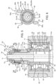
- number 1 denotes in particular a helicopter essentially comprising:
- the helicopter 1 also comprises a transmission group 11, which transmits the motion from the turbines 5 to the main rotor 3.
- the transmission group 11 comprises, in turn:
- the rotor 3 is adapted to provide an orientable thrust which allows the helicopter 1 to be lifted and moved forward. Furthermore, the actuation of the rotor 3, in a known manner, generates a reaction torque around the axis E on the helicopter 1.
- This contrasting torque is oriented in the opposite direction to the torque exerted on the rotor 3.
- the thrust value generated by the rotor 4 it is therefore possible to orient the helicopter 1 according to a desired yaw angle around the axis E, or to vary the aforesaid yaw angle according to the manoeuvre to be performed.
- the rotor 4 essentially comprises:
- the blades 8 are articulated on the hub 9 so as to:
- the hub 9 comprises a plurality of attachment elements 27 radially projecting with respect to the axis A for the connection to respective blades 8.
- Each blade 8 also comprises a root portion 14 arranged radially internal with respect to the axis A and articulated on the relative attachment element 27 of the hub 9 ( Figures 2 , 3 and 4 ).
- the rotor 4 further comprises a control device 50 for varying the angle of attack of the blades 8, that is, the angles of attack of the blades 8.
- the helicopter 1 further comprises a flight control 15 (only schematically shown in Figure 1 ), for example a pedalboard, which can be operated by the pilot in order to permit the variation of the aforesaid angles of attack.
- a flight control 15 for example a pedalboard, which can be operated by the pilot in order to permit the variation of the aforesaid angles of attack.
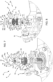
- the control unit 50 comprises ( Figures 3 and 4 ):
- the shaft 6 is hollow.
- the shaft 6 further comprises ( Figure 3 ):
- the shaft 6 has a maximum diameter at the flange 19, and progressively decreasing diameters proceeding from the flange 19 towards the ends 20, 21.
- the rod 10 is partially housed inside by shaft 6.
- the rod 10 further comprises:
- the ends 23, 24 are arranged externally to the shaft 6 and on the side of the ends 20, 21, respectively.
- the main body 25 is operatively connected to the flight control 15 by means of a lever mechanism (not shown) or by means of a wireless type drive.
- the flange 42 is connected to the shaft 6 by a single variable-length bellows 44, which allows it to slide along the axis A.
- lever mechanisms 43 are articulated on the root portions 14 of the respective blades 8.
- the internal ring 31 is made integral with the control rod 10 by means of constraint conditions which act both axially and radially with respect to the axis A.
- constraint conditions which act both axially and radially with respect to the axis A.
- the movement of the internal ring 31 with respect to the control rod 10 parallel to the axis A is prevented both in the direction oriented from the end 23 to the end 24, and in the opposite direction.
- the movement of the ring 31 with respect to the control rod 10 in the radial direction is prevented by an interference coupling.
- the internal ring 31 comprises an axial end 31a, which is arranged on the side of the end 23, and an axial end 31b opposite the end 31a.
- the control rod 10 further comprises a threaded portion 10a and the control device 50 further comprises a threaded element 51, which is screwed onto the control rod 10 at the threaded portion 10a and cooperating with the axial end 31b ( Figures 4 and 5 ). In this way, the axial constraint of the internal ring 31 is realized on the side of the axial end 31b.
- the threaded element 51 is a locking nut.
- the threaded portion 10a is obtained in proximity to the end 24 and, in particular, along an axial section of the control rod 10 extending from the side opposite the shoulder 39 with respect to the bearing 17.
- Control device 50 comprises a bushing 52 coupled in an angularly and axially fixed manner to the threaded element 51 and in an angularly fixed manner to the control rod 10.
- the bushing 52 is coupled in an angularly fixed manner to the control rod 10 independently of the threaded element 51. Therefore, even if the bushing 52 were not angularly fixed with respect to the threaded element 51, the bushing 52 could not rotate with respect to the control rod 10.
- the bushing 52 constitutes an anti-unscrewing device of the threaded element 51 with respect to the control rod 10.
- the bushing 52 exerts a contrasting action on the threaded element 51, which is the resultant of a plurality of forces and/or moments and which opposes the rotation of the threaded element 51 with respect to the control rod 10.
- the bushing 52 is a cylindrical body mounted coaxially to the axis A on the side opposite the end 23 with respect to the threaded element 51.
- the bushing 52 comprises a radially internal portion 58 and a radially external portion 57.
- the bushing 52 further comprises an axial end 52a which is arranged on the side of the end 23 and an axial end 52b which is axially opposite to the end 52a ( Figures 5 to 9 ).
- the bushing 52 comprises a cylindrical section 53 arranged on the side of the axial end 52a and a cylindrical section 54 arranged on the side of the axial end 52b.
- the cylindrical sections 53 and 54 are concentric to each other and superimposed the one above the other parallel to the axis A.
- the cylindrical sections 53 and 54 have respective external diameters that are different from each other.
- the external diameter of the cylindrical section 53 is greater than that of the cylindrical section 54.
- the axial extension of the cylindrical section 54 is smaller than that of the cylindrical section 53.
- the bushing 52 is angularly coupled to the control rod 10 by means of a shape coupling 70 and the bushing 52 is angularly coupled to the threaded element 51 by means of a shape coupling 60, which is distinct from shape coupling 70;
- profile 71, 71' comprises an even number of first interfaces 71b, 71b'; profile 72, 72' comprises an even number of second interfaces 72b, 72b'; profile 61 comprises an odd number of third interfaces 64 and profile 62 comprises an odd number of fourth interfaces.
- first and second interfaces 71b, 72b; 71b', 72b' may be odd and third and fourth interfaces 64, 65 may be even.
- first and second interfaces 71b, 72b; 71b', 72b' is not a multiple of the number of third and fourth interfaces 64, 65 and the number of third and fourth interfaces 64, 65 is not a multiple of the number of first and second interfaces 61, 62.
- a ratio r between the greatest of the number of the first, second, third and fourth interfaces 71b, 72b; 71b', 72b', 64, 65 and the smallest of the number of the first, second, third and fourth interfaces 71b, 72b; 71b', 72b', 64, 65 is greater than 3.
- r max first , second , third and fourth interfaces min first , second , third and fourth interfaces > 3 r , r ⁇ 1 ⁇ Z
- ratio r is greater than 4, 5 or 6.
- the number of first interfaces 71b, 71b' may be equal to or different from the number of second interfaces 72, 72b'; the number of third interfaces 64 may be equal to or different from the number of fourth interfaces 65.
- the threaded element 51 comprises profile 61 at the radially external portion 55 and the bushing 52 comprises profile 62 that is complementary in shape to that of the profile 61 at the radially internal portion 58 ( Figures 7, 8 and 10 ).
- the profile 61 is a radially external grooved profile 61 and the profile 62 is a radially internal grooved profile 62.
- the radially external grooved profile 61 and the radially internal grooved profile 62 are such that they can be reversibly coupled to each other.
- the external and internal grooved profiles 61, 62 can be made by means of a broaching process.
- third and fourth interfaces 64, 65 are teeth 64, 65, preferably straight parallel to the axis A.
- the number of teeth 64 and the number of teeth 65 are odd.
- the number of teeth 64 and the number of teeth 65 are greater than forty.
- radially external grooved profile 61 comprise forty-one teeth 64 and radially internal grooved profile 62 comprise forty-one teeth 65 ( figure 6 ).
- the meshing between the teeth 64 and the teeth 65 prevents the threaded element 51 and the bushing 52 from rotating the one with respect to the other.
- the axial extension of the external and internal grooved profiles 61, 62 is related to the contrasting action that the bushing 52 exerts on the threaded element 51.
- the extent of the contrasting action increases as the axial extension of the external and internal grooved profiles 61, 62 increases.
- the threaded element 51 comprises a cylindrical section 51a arranged on the side of the end 23 and a cylindrical section 51b arranged on the side of the end 24.
- the cylindrical sections 51a and 51b are concentric to each other and superimposed the one above the other parallel to the axis A.
- the threaded element 51 is of the non-self-braking type.
- the profile 72 has a shape corresponding to that of the profile 71 and defines the perimeter of a through hole obtained at the axial end 52b and having an axis parallel to the axis A ( Figure 7 ).
- the profile 72 is formed by a plurality of seats engaged by respective elements 71b.
- the profile 72 comprises an annular portion 72a concentric to the axis A and a plurality of elements 72b projecting radially from the annular portion 72a and angularly equidistant to each other around the axis A.
- the elements 72b are teeth connected to the annular portion 72a, contiguous to each other and are six in number.
- the profile 72 has the shape of a six-pointed star in a section perpendicular to the axis A.
- Elements 72b define the second interfaces of profile 72.
- bushing 52 may be coupled to control rod 10 in six discrete angular positions with respect to axis A.
- the profile 71' has a square shape in a plane orthogonal to the axis A and the profile 72' is shaped to engage the profile 71'.
- profile 71' comprises four vertices 71b' and profile 72' comprises an annular portion 72a' concentric to the axis A and a plurality of elements 72b' projecting radially from the annular portion 72a' and angularly equidistant to each other around the axis A.
- Elements 72b' are teeth connected to the annular portion 72a', contiguous to each other and are eight in number.
- the profile 72' has the shape of an eight-pointed star in a section perpendicular to the axis A.
- Elements 71b' define the first interfaces of profile 71' and elements 72b' define the second interfaces of profile 72'.
- bushing 52 may be coupled to control rod 10 in eight discrete angular positions with respect to axis A.
- control device 50 comprises axial fixing means 80, which make the threaded element 51 and the bushing 52 axially integral.
- the axial fixing means 80 constitute additional anti-unscrewing devices that are adapted to prevent the accidental unscrewing of the threaded element 51 from the threaded portion 10a.
- the axial fixing means 80 comprise ( Figure 10 ):
- the seats 81, 82 are arranged at the radially external portion 55.
- the seats 81, 82 are spaced apart parallel to the axis A and are preferably identical to each other ( Figures 7, 8 and 10 ) .
- the seats 81 and 82 extend along the entire circumference of the radially external portion 55 on respective planes perpendicular to the axis A. Furthermore, the seats 81 and 82 are obtained at the cylindrical section 51b and in particular at the external grooved profile 61. More particularly, the seats 81 and 82 radially define a recess with respect to the head of the teeth 64.
- the two groups of openings 83a, 83b, 84a, 84b are each obtained at respective distinct parts of the bushing 52.
- the two groups of openings 83a, 83b, 84a, 84b are diametrically opposite to each other.
- the group of openings comprises two inlet openings 83a, 84a for the insertion of the filiform deformable element 85 and two outlet openings 83b, 84b for the exit of the filiform deformable element 85.
- the inlet openings 83a, 84a are aligned with each other parallel to the axis A and the same applies to the outlet openings 83b, 84b.
- the inlet opening 83a is aligned with the outlet opening 83b and the inlet opening 84a is aligned with the outlet opening 84b circumferentially with respect to the axis A.
- the openings 83a, 83b, 84a, 84b, moreover, are obtained at the cylindrical section 53.
- the two groups of seats 86, 87 which each comprise two seats, are also obtained at the cylindrical section 53 ( Figure 8 ). Furthermore, the two seats 86, 87 of each group of seats are spaced apart parallel to the axis A and are preferably identical to each other. More in detail, the seats 86 and 87 of each pair of seats extend along a circular sector of the bushing 52.
- the seats 86 and 87 are obtained at the internal groove profile 62.
- the seats 86 and 87 also radially define a recess with respect to the head of the teeth 65.
- the distance between a seat 86 and the relative seat 87 parallel to the axis A is equal to the axial distance between the seats 81 and 82 parallel to the axis A.
- the seats 81, 82, 86 and 87 are shaped so as to house the filiform deformable element 85.
- FIGS 7, 8 and 10 show the filiform deformable element 85 in an initial configuration, i.e. before it is engaged with the threaded element 51 and the bushing 52.
- the filiform deformable element 85 comprises two straight sections 88, 89 and parallel to each other and a curvilinear section 90, which joins the two straight sections 88, 89.
- the filiform deformable element 85 also comprises two free ends 85a, 85b opposite each other, which are defined respectively by the straight sections 88 and 89 on the side opposite to the curvilinear section 90.
- the filiform deformable element 85 is preferably made of metallic material and is, for example, a brake wire.
- the seats 81 and 82 are at least partially facing the seats 86 and 87 respectively and house respective portions of the filiform deformable element 85.
- the filiform deformable element 85 has a circular cross-section. Consequently, the seats 81, 82, 86 and 87 have an arc-shaped profile of a circumference in a plane passing through the axis A.
- the filiform deformable element 85 may have a cross section with shapes other than the circular one.
- Figure 9 shows the filiform deformable element 85 in a final configuration, i.e. once the filiform deformable element 85 is engaged with the threaded element 51 and with the bushing 52.
- the straight section 88 which is placed on the side of the end 23, passes through the inlet opening 83a, engages the seats 81 and 86 and comes out from the outlet opening 83b;
- the straight section 89 which is placed on the side of the end 24, passes through the inlet opening 84a, engages the seats 82, 87 and comes out from the outlet opening 84b.
- each straight section 88, 89 is partially housed in the seats 81, 82, 86, 87 and partially outside these seats.
- the curvilinear section 90 and the free ends 85a, 85b are outside the seats 81, 82, 86, 87.
- the free ends 85a, 85b are plastically deformed so that they are twisted together and then fixed the one to the other. Consequently, the free ends 85a, 85b place the filiform deformable element 85 under traction and prevent the straight sections 88, 89 from being able to vary their distance parallel to the axis A during use.
- the straight section 88 is interposed between two sections of the teeth 64 and two sections of the teeth 65 parallel to the axis A.
- the straight section 89 is interposed between two sections of the teeth 64 and two sections of the teeth 65 parallel to the axis A. Therefore, as a consequence of the tensile stress to which the filiform deformable element 85 is subjected, the straight sections 88 and 89 exert respective actions parallel to the axis A and oriented towards the end 24 and towards the end 23, respectively.
- the control device 50 also comprises a washer 100, which is fitted around the control rod 10 and axially interposed between the bearing 17 and the threaded element 51.
- the washer 100 axially abuts against the internal ring 31 at the end 31b and against the threaded element 51 on the side of the cylindrical section 51a.
- the bearing 17 is fitted from the end 24 coaxially to the axis A and slid axially until the internal ring 31 abuts against the shoulder 39 at the axial end 31a.
- the washer 100 is inserted, which is placed so as to abut against the axial end 31b.
- the threaded element 51 is therefore also fitted around the control rod 10 from the end 24 and from the side of the cylindrical section 51a.
- the threaded element 51 is then rotated about the axis A, so that the radially internal portion 56 is screwed onto the threaded portion 10a.
- the threaded element 51 is progressively screwed - for example by means of a torque wrench - around the control rod 10 until it is tightened to the predetermined torque.
- the threaded element 51 abuts against the washer 100 on the side of the cylindrical section 51a.
- the bushing 52 is then inserted from the end 24 so as to be axially stacked with the threaded element 51.
- the shape coupling 60 and the shape coupling 70 are both geometrically respected. Therefore, it is necessary that profile 61 is correctly coupled to the profile 62 and that at the same time the profile 71, 71' is correctly coupled to the profile 72, 72'.
- the teeth 64 of the external grooved profile 61 must be angularly placed so as to be able to mesh correctly with the teeth 65 of the internal grooved profile 62 and at the same time, the elements 71b must be able to engage the corresponding seats of the profile 72 or that the square-shaped profile 71' can geometrically engage the profile 72'.
- bushing 52 has to be rotated about axis A to another of the discrete angular positions in which profile 71, 71' is correctly coupled to the profile 72, 72' until teeth 64 and 65 correctly mesh with one another.
- the relative angular position between teeth 64 and 64 is different in each of the discrete angular positions of the bushing 52 with respect to control rod 10.
- different portions of the surfaces of the teeth 64, 65 face and contact one another in each of the discrete angular positions and the teeth 64, 65 mesh in at least one of the angular positions of the bushing relative 52 to the control rod 10.
- the bushing 52 is angularly fixed with respect to the threaded element 51 and with respect to the control rod 10.
- each filiform deformable element 85 is inserted partly into the seats 81, 86 and partly into the seats 82, 87, and deformed at its free ends 85a, 85b which come out from the seats 81, 82, 86, 87, in order to prevent the relative axial displacement between the threaded element 51 and the bushing 52 ( Figure 6 ).
- the straight section 88 is inserted from the free end 85a through the inlet opening 83a into the seats 81 and 86 until it partially comes out from the outlet opening 83b; at the same time, the straight section 89 is inserted from the free end 85b through the inlet opening 84a into the seats 82, 87 until it partially comes out from the outlet opening 84b.
- the free ends 85a and 85b are then twisted together so that they are fixed the one to the other.
- the actuation of the rotor 4 results in the rotation of the shaft 6 and of the hub 9 around the axis A and, consequently, the generation of the contrasting torque on the fuselage 2.
- the rotation of the rotor 4 causes vibrations to be triggered, which are transmitted to the threaded element 51 through the control rod 10 and which tend to unscrew the threaded element 51 itself from the threaded portion 10a.
- the bushing 52 is angularly integral with the threaded element 51 by means of the shape coupling 60 and the control rod 10 by means of the shape coupling 70. Therefore, the rotation of the threaded element 51 about the axis A is prevented by the fact that the bushing 52 cannot rotate with respect to the control rod 10.
- the filiform deformable elements 85 which are housed in the seats 81, 82 and in the seats 86, 87, exert on the threaded element 51 and on the bushing 52 actions directed parallel to the axis A, which oppose the distancing between the bushing 52 and the threaded element 51.
- the bushing 52 is angularly and axially fixed to the threaded element 51 and is angularly fixed to the control rod 10.
- the axial displacement of the radial internal ring 31 with respect to the control rod 10 can be reliably and efficiently limited.
- bushing 52 can be coupled to the control rod 10 and the threaded element 51, in such a manner as to efficiently and reliably ensure the axial preload required by the rolling bearing 17.
- first and second interfaces 71b, 72b; 71b', 72' are even and third and fourth interfaces 64, 65 are odd or vice versa, the bushing 52 can be coupled to the threaded element 51 and the control rod 10 without requiring angular clearance therebetween.
- first, second, third and fourth interfaces 71b, 71b', 72b, 72b', 64, 65 were all even or all odd, the mounting of the bushing 52 to the threaded element 51 and the control rod 10 would only be ensured if an angular clearance were present between the bushing 52 and the control rod 10. However, the angular clearance does not ensure the axial preload required by the rolling bearing 17.
- the threaded element 51 can be used for a much greater number of tightening cycles than that allowed by the self-braking nuts.
- the axial locking element 38 could comprise an elastic stop ring, for example a Seeger ring.
- the profiles 71, 71'; 72, 72' may be shaped differently, i.e. have complementary shapes other than those shown in Figures 7 and 10 .
- the profile 71 could comprise a number of elements 71b other than six.
- Profiles 71, 71' and 72, 72' may be shaped respectively as external and internal grooved profiles.
- Profile 61 could be polygonal and profile 62 could be polygonal and with a shape complementary to that of the profile 61.
- the filiform deformable element 85 may be different from a brake wire.
- the filiform deformable element 85 may be a split pin.
Landscapes
- Engineering & Computer Science (AREA)
- Mechanical Engineering (AREA)
- Aviation & Aerospace Engineering (AREA)
- General Engineering & Computer Science (AREA)
- Mutual Connection Of Rods And Tubes (AREA)
- Chairs For Special Purposes, Such As Reclining Chairs (AREA)
- Transmission Devices (AREA)
Claims (13)
- Steuervorrichtung (50) zum Steuern der Veränderung des Anstellwinkels der Blätter (8) eines Drehmomentausgleichsrotors (4) für ein schwebfähiges Luftfahrzeug (1), die Folgendes umfasst:- ein Steuerelement (16), das entlang einer ersten Achse (A) in Bezug auf eine Welle (6) des Drehmomentausgleichsrotors (4) gleitet und sich einteilig mit der Welle (6) drehen kann; wobei das Steuerelement (16) außerdem betriebstechnisch mit mehreren der Blätter (8) verbunden ist, die an der Welle (6) angelenkt sind, um im Gebrauch ihre Drehung um jeweilige zweite Achsen (B) einer Translation des Elements (16) selbst entlang der ersten Achse (A) folgend zu bewirken;- einen Steuerstab (10), der entlang der ersten Achse (A) in Bezug auf die Welle (6) axial gleitet und in Bezug auf die erste Achse (A) in Winkelrichtung fest ist; und- ein Wälzlager (17), das zwischen dem Steuerstab (10) und dem Steuerelement (16) eingefügt ist, entlang der ersten Achse (A) in Bezug auf die Welle (6) und einteilig mit dem Steuerstab (10) gleitet und konfiguriert ist, die relative Drehung des Steuerelements (16) in Bezug auf den Steuerstab (10) um die erste Achse (A) zu ermöglichen;wobei das Wälzlager (17) seinerseits Folgendes umfasst:- einen ersten Ring (30), der einteilig mit dem Steuerelement (16) um die erste Achse (A) drehbar ist;- einen zweiten Ring (31), der sich in Bezug auf die erste Achse (A) radial innerhalb des ersten Rings (30) befindet und einteilig mit dem Steuerstab (10) entlang der ersten Achse (A) gleitet; und- mehrere Wälzkörper (32), die zwischen dem ersten und dem zweiten Ring (30, 31) eingefügt sind und ausgelegt sind, auf jeweiligen Bahnen (33, 34) des ersten und des zweiten Rings (30, 31) zu rollen;wobei die Steuervorrichtung (50) ferner Folgendes umfasst:- ein Gewindeelement (51), das auf den Steuerstab (10) geschraubt ist und mit dem zweiten Ring (31) zusammenwirkt, um ihn in Bezug auf den Steuerstab (10) axial zu begrenzen;- eine Buchse (52), die auf eine in Winkelrichtung und axial feste Weise mit dem Gewindeelement (51) und auf eine in Winkelrichtung feste Weise mit dem Steuerstab (10) gekoppelt ist; und- erste Verbindungsmittel (70), die ausgelegt sind, die Buchse (52) mit dem Steuerstab (10) zu verbinden;wobei der Steuerstab (10) ein erstes Profil (71, 71') umfasst und die Buchse (52) ein zweites Profil (72, 72') umfasst; wobei das Gewindeelement (51) ein drittes Profil (61) umfasst;dadurch gekennzeichnet, dass sie Folgendes umfasst:- zweite Verbindungsmittel (60), die sich von den ersten Verbindungsmitteln (70) unterscheiden und ausgelegt sind, die Buchse (52) mit dem Gewindeelement (51) zu verbinden;wobei die ersten Verbindungsmittel (70) eine Kopplung (70) mit einer ersten Form umfassen und die zweiten Verbindungsmittel (60) eine Kopplung (60) mit einer zweiten Form umfassen;wobei das erste Profil (71, 71') mehrere erste Grenzflächen (71b, 71b') umfasst und das zweite Profil (72, 72') mehrere zweite Grenzflächen (72b, 72b') umfasst; wobei die ersten und die zweiten Grenzflächen (71b, 72b; 71b', 72b') miteinander gekoppelt sind und die Kopplung (70) mit einer ersten Form definieren;wobei die Buchse (52) ein viertes Profil (62) umfasst; wobei das dritte Profil (61) mehrere dritte Grenzflächen (64) umfasst und das vierte Profil (62) mehrere vierte Grenzflächen (64, 65) umfasst; wobei die dritten und die vierten Grenzflächen (64, 65) miteinander gekoppelt sind und die Kopplung (60) mit einer zweiten Form definieren,ferner dadurch gekennzeichnet, dass die ersten und die zweiten Grenzflächen (71b, 72b; 71b', 72') geradzahlig sind und die dritten und die vierten Grenzflächen (64, 65) ungeradzahlig sind; oderdie ersten und die zweiten Grenzflächen (71b, 72b; 71b', 72') ungeradzahlig sind und die dritten und die vierten Grenzflächen (64, 65) geradzahlig sind,ferner dadurch gekennzeichnet, dass die Anzahl der ersten und der zweiten Grenzflächen (71b, 72b; 71b', 72b') kein Vielfaches der Anzahl der dritten und der vierten Grenzflächen (64, 65) ist und dass die Anzahl der dritten und der vierten Grenzflächen (64, 65) kein Vielfaches der Anzahl der ersten und der zweiten Grenzflächen (71b, 72b; 71b', 72') ist.
- Steuervorrichtung nach Anspruch 1, wobei ein Verhältnis (r) zwischen der größten der Anzahl der ersten, zweiten, dritten und vierten Grenzflächen (71b, 72b; 71b', 72', 64, 65) und der kleinsten der Anzahl der ersten, zweiten, dritten und vierten Grenzflächen (71b, 72b; 71b', 72', 64, 65) größer als 3 ist.
- Steuervorrichtung nach Anspruch 1 oder 2, dadurch gekennzeichnet, dass das Gewindeelement (51) einen ersten radial äußeren Abschnitt (55) und einen ersten radial inneren Abschnitt (56) in Bezug auf die erste Achse (A) umfasst und die Buchse (52) einen zweiten radial äußeren Abschnitt (57) und einen zweiten radial inneren Abschnitt (58) umfasst;
wobei das dritte Profil (61) ein Außennutprofil (61) umfasst und am ersten radial äußeren Abschnitt (55) angeordnet ist und das vierte Profil (62) ein Innennutprofil (62) umfasst und am zweiten radial inneren Abschnitt (58) angeordnet ist; wobei das Außennutprofil (61) und das Innennutprofil (62) miteinander gekoppelt sind und die Kopplung (60) mit einer zweiten Form definieren. - Steuervorrichtung nach Anspruch 3, dadurch gekennzeichnet, dass das Außennutprofil (61) eine ungerade Anzahl der dritten Grenzflächen (64) umfasst und das Innennutprofil (62) eine ungerade Anzahl der vierten Grenzflächen (65) umfasst; wobei die dritten und die vierten Grenzflächen (64, 65) Zähne sind.
- Steuervorrichtung nach Anspruch 3 oder 4, dadurch gekennzeichnet, dass das Außennutprofil (61) und das Innennutprofil (62) jeweilige axiale Ausdehnungen parallel zur ersten Achse (A) aufweisen;wobei die Buchse (52) im Gebrauch eine Gegenwirkung auf das Gewindeelement (51) ausübt;wobei die Gegenwirkung eine Resultierende der Kräfte und/oder Momente ist, die eine Richtung aufweisen, die zur Drehung des Gewindeelements (51) um die erste Achse (A) entgegengesetzt ist, und ein Modul aufweisen, das zu den axialen Ausdehnungen proportional ist.
- Steuervorrichtung nach einem der vorhergehenden Ansprüche, dadurch gekennzeichnet, dass das erste Profil (71, 71') ein erstes polygonales Profil (71, 71') umfasst und das zweite Profil (72, 72') ein zweites polygonales Profil (72, 72') mit einer Form, die dem ersten polygonalen Profil (71, 71') entspricht, umfasst;
wobei das erste polygonale Profil (71, 71') und das zweite polygonale Profil (72, 72') miteinander gekoppelt sind und die Kopplung (70) mit einer ersten Form definieren. - Steuervorrichtung nach einem der vorhergehenden Ansprüche, gekennzeichnet durch das Umfassen axialer Arretierungsmittel (80);
wobei die axialen Arretierungsmittel (80) ausgelegt sind, das Gewindeelement (51) und die Buchse (52) aneinander zu arretieren, um ihre relativen Bewegungen parallel zur ersten Achse (A) zu verhindern. - Steuervorrichtung nach Anspruch 7, dadurch gekennzeichnet, dass die axialen Arretierungsmittel (80) Folgendes umfassen:- mindestens einen ersten Sitz (81, 82), der am Gewindeelement (51) gebildet ist;- mehrere Öffnungen (83a, 83b, 84a, 84b), die an der Buchse (52) gebildet sind;- mindestens einen zweiten Sitz (86, 87), der an der Buchse (52) erhalten wird und zumindest teilweise dem ersten Sitz (81, 82) zugewandt ist; und- ein fadenförmiges, verformbares Element (85), das sich mit dem ersten und dem zweiten Sitz (81, 82; 86, 87) und den Öffnungen (83a, 83b, 84a, 84b) in Eingriff befindet.
- Steuervorrichtung nach Anspruch 8, dadurch gekennzeichnet, dass das fadenförmige, verformbare Element (85) aus einem metallischen Material hergestellt ist.
- Steuervorrichtung nach einem der vorhergehenden Ansprüche, dadurch gekennzeichnet, dass das Gewindeelement (51) ein nicht selbstbrechender Typ ist.
- Steuervorrichtung nach einem der vorhergehenden Ansprüche, dadurch gekennzeichnet, dass sie eine Ringscheibe (100) umfasst, die um den Steuerstab (10) eingepasst ist und zwischen dem Wälzlager (17) und dem Gewindeelement (51) parallel zur ersten Achse (A) eingefügt ist.
- Drehmomentausgleichsrotor (4) für ein schwebfähiges Luftfahrzeug (1), der Folgendes umfasst:- eine Welle (6), die sich um eine erste Achse (A) drehen kann;- mehrere Blätter (8), die auf der Welle (6) angelenkt sind, sich entlang jeweiliger zweiter Achsen (B) transversal zur ersten Achse (A) erstrecken und um die jeweiligen zweiten Achsen (B) drehbar sind, um die jeweiligen Anstellwinkel zu verändern; und- eine Steuervorrichtung (50) nach einem der vorhergehenden Ansprüche.
- Schwebfähiges Luftfahrzeug (1), insbesondere ein Helikopter (1), das Folgendes umfasst:- einen Rumpf (2);- einen Hauptrotor (3); und- einen Drehmomentausgleichsrotor (4) nach Anspruch 12.
Applications Claiming Priority (2)
| Application Number | Priority Date | Filing Date | Title |
|---|---|---|---|
| EP21205724.4A EP4173949B1 (de) | 2021-10-29 | 2021-10-29 | Steuerungsvorrichtung zur veränderung des anstellwinkels der blätter eines heckrotors für ein schwebfähiges flugzeug |
| PCT/IB2022/055834 WO2023073440A1 (en) | 2021-10-29 | 2022-06-23 | Control device for varying the angle of attack of the blades of an anti-torque rotor for an aircraft capable of hovering |
Publications (2)
| Publication Number | Publication Date |
|---|---|
| EP4422972A1 EP4422972A1 (de) | 2024-09-04 |
| EP4422972B1 true EP4422972B1 (de) | 2025-03-26 |
Family
ID=79170761
Family Applications (2)
| Application Number | Title | Priority Date | Filing Date |
|---|---|---|---|
| EP21205724.4A Active EP4173949B1 (de) | 2021-10-29 | 2021-10-29 | Steuerungsvorrichtung zur veränderung des anstellwinkels der blätter eines heckrotors für ein schwebfähiges flugzeug |
| EP22735037.8A Active EP4422972B1 (de) | 2021-10-29 | 2022-06-23 | Steuerungsvorrichtung zur veränderung des anstellwinkels der blätter eines heckrotors für ein schwebfähiges flugzeug |
Family Applications Before (1)
| Application Number | Title | Priority Date | Filing Date |
|---|---|---|---|
| EP21205724.4A Active EP4173949B1 (de) | 2021-10-29 | 2021-10-29 | Steuerungsvorrichtung zur veränderung des anstellwinkels der blätter eines heckrotors für ein schwebfähiges flugzeug |
Country Status (4)
| Country | Link |
|---|---|
| EP (2) | EP4173949B1 (de) |
| KR (1) | KR20240091193A (de) |
| CN (1) | CN118176151A (de) |
| WO (1) | WO2023073440A1 (de) |
Citations (1)
| Publication number | Priority date | Publication date | Assignee | Title |
|---|---|---|---|---|
| US20160363155A1 (en) * | 2015-06-09 | 2016-12-15 | Airbus Operations Limited | Pin assembly |
Family Cites Families (4)
| Publication number | Priority date | Publication date | Assignee | Title |
|---|---|---|---|---|
| US121176A (en) * | 1871-11-21 | Improvement in lock-nuts | ||
| WO2017020286A1 (zh) | 2015-08-06 | 2017-02-09 | 杨东佐 | 一种锁紧螺母、止转结构、紧固连接组件及结构、安装及拆卸方法、轨道结构、曲轴连杆机构、骨连接装置及骨连接方法、连接轴装置、车轮骨架、自行车珠堵及珠堵装置及车轮架 |
| FR3067769B1 (fr) * | 2017-06-15 | 2019-07-19 | Lisi Aerospace | Fixation a verrouillage positif |
| EP3753849B1 (de) * | 2019-06-17 | 2021-08-04 | LEONARDO S.p.A. | Drehmomentausgleichsrotor für einen hubschrauber |
-
2021
- 2021-10-29 EP EP21205724.4A patent/EP4173949B1/de active Active
-
2022
- 2022-06-23 EP EP22735037.8A patent/EP4422972B1/de active Active
- 2022-06-23 WO PCT/IB2022/055834 patent/WO2023073440A1/en not_active Ceased
- 2022-06-23 CN CN202280072707.6A patent/CN118176151A/zh active Pending
- 2022-06-23 KR KR1020247017983A patent/KR20240091193A/ko active Pending
Patent Citations (1)
| Publication number | Priority date | Publication date | Assignee | Title |
|---|---|---|---|---|
| US20160363155A1 (en) * | 2015-06-09 | 2016-12-15 | Airbus Operations Limited | Pin assembly |
Also Published As
| Publication number | Publication date |
|---|---|
| KR20240091193A (ko) | 2024-06-21 |
| EP4422972A1 (de) | 2024-09-04 |
| EP4173949A1 (de) | 2023-05-03 |
| WO2023073440A1 (en) | 2023-05-04 |
| EP4173949B1 (de) | 2024-12-04 |
| CN118176151A (zh) | 2024-06-11 |
Similar Documents
| Publication | Publication Date | Title |
|---|---|---|
| EP1853436B1 (de) | Stirnverzahnung für eine antreibbare radnabe | |
| JP2768826B2 (ja) | 回転翼型航空機の尾部回転翼のダクトファンおよびピッチ制御装置 | |
| EP2302244B1 (de) | Kraftübertragungsvorrichtung | |
| US10377502B2 (en) | Beam springs for aircraft engine mount assemblies | |
| US5160005A (en) | Pawl and ratchet clutch with torsion shaft | |
| DE69101667T2 (de) | Taumelscheibenvorrichtung mit in Nicken und Rollen ausgekuppelten Gelenken montiert für die Einstellwinkelsteuerung der Rotorblätter eines Drehflügelflugzeuges. | |
| EP3514054B1 (de) | Vorrichtung und verfahren zum aufrüsten einer drehröhrenanordnung in einem flugzeug | |
| CA2897592C (en) | Flexible coupling | |
| EP4422972B1 (de) | Steuerungsvorrichtung zur veränderung des anstellwinkels der blätter eines heckrotors für ein schwebfähiges flugzeug | |
| US6692399B2 (en) | Differential torque limiter | |
| DE19753106C2 (de) | Lastdrehmomentsperre | |
| EP4409161B1 (de) | Elektrische antriebseinrichtung | |
| DE112008001555B4 (de) | Kraftübertragung | |
| DE102015201146B4 (de) | Harmonisches Getriebe | |
| EP3137377B1 (de) | Radial elastische hohlwelle | |
| US8240601B2 (en) | Coupling with slack-takeup, a rotor, and a rotary wing aircraft | |
| EP3767120B1 (de) | Drehmomentbegrenzungsvorrichtung | |
| US11649039B1 (en) | Aerostructure actuation system | |
| CN223014890U (zh) | 旋翼头和直升机 | |
| EP4470722B1 (de) | Verlängerungsentfernungswerkzeug | |
| US20070104580A1 (en) | Rotorcraft rotors having twistable blades | |
| EP4015856B1 (de) | Stellglied für heckrotor | |
| CN119037704A (zh) | 旋翼头和直升机 | |
| CH367357A (de) | Nachgiebige Wellenkupplung |
Legal Events
| Date | Code | Title | Description |
|---|---|---|---|
| STAA | Information on the status of an ep patent application or granted ep patent |
Free format text: STATUS: UNKNOWN |
|
| STAA | Information on the status of an ep patent application or granted ep patent |
Free format text: STATUS: THE INTERNATIONAL PUBLICATION HAS BEEN MADE |
|
| PUAI | Public reference made under article 153(3) epc to a published international application that has entered the european phase |
Free format text: ORIGINAL CODE: 0009012 |
|
| STAA | Information on the status of an ep patent application or granted ep patent |
Free format text: STATUS: REQUEST FOR EXAMINATION WAS MADE |
|
| 17P | Request for examination filed |
Effective date: 20240424 |
|
| AK | Designated contracting states |
Kind code of ref document: A1 Designated state(s): AL AT BE BG CH CY CZ DE DK EE ES FI FR GB GR HR HU IE IS IT LI LT LU LV MC MK MT NL NO PL PT RO RS SE SI SK SM TR |
|
| GRAP | Despatch of communication of intention to grant a patent |
Free format text: ORIGINAL CODE: EPIDOSNIGR1 |
|
| STAA | Information on the status of an ep patent application or granted ep patent |
Free format text: STATUS: GRANT OF PATENT IS INTENDED |
|
| DAV | Request for validation of the european patent (deleted) | ||
| DAX | Request for extension of the european patent (deleted) | ||
| INTG | Intention to grant announced |
Effective date: 20241024 |
|
| P01 | Opt-out of the competence of the unified patent court (upc) registered |
Free format text: CASE NUMBER: APP_65371/2024 Effective date: 20241211 |
|
| GRAS | Grant fee paid |
Free format text: ORIGINAL CODE: EPIDOSNIGR3 |
|
| GRAA | (expected) grant |
Free format text: ORIGINAL CODE: 0009210 |
|
| STAA | Information on the status of an ep patent application or granted ep patent |
Free format text: STATUS: THE PATENT HAS BEEN GRANTED |
|
| AK | Designated contracting states |
Kind code of ref document: B1 Designated state(s): AL AT BE BG CH CY CZ DE DK EE ES FI FR GB GR HR HU IE IS IT LI LT LU LV MC MK MT NL NO PL PT RO RS SE SI SK SM TR |
|
| REG | Reference to a national code |
Ref country code: GB Ref legal event code: FG4D |
|
| REG | Reference to a national code |
Ref country code: CH Ref legal event code: EP |
|
| REG | Reference to a national code |
Ref country code: DE Ref legal event code: R096 Ref document number: 602022012313 Country of ref document: DE |
|
| REG | Reference to a national code |
Ref country code: IE Ref legal event code: FG4D |
|
| PG25 | Lapsed in a contracting state [announced via postgrant information from national office to epo] |
Ref country code: RS Free format text: LAPSE BECAUSE OF FAILURE TO SUBMIT A TRANSLATION OF THE DESCRIPTION OR TO PAY THE FEE WITHIN THE PRESCRIBED TIME-LIMIT Effective date: 20250626 |
|
| PG25 | Lapsed in a contracting state [announced via postgrant information from national office to epo] |
Ref country code: FI Free format text: LAPSE BECAUSE OF FAILURE TO SUBMIT A TRANSLATION OF THE DESCRIPTION OR TO PAY THE FEE WITHIN THE PRESCRIBED TIME-LIMIT Effective date: 20250326 |
|
| PGFP | Annual fee paid to national office [announced via postgrant information from national office to epo] |
Ref country code: DE Payment date: 20250626 Year of fee payment: 4 |
|
| REG | Reference to a national code |
Ref country code: LT Ref legal event code: MG9D |
|
| PG25 | Lapsed in a contracting state [announced via postgrant information from national office to epo] |
Ref country code: NO Free format text: LAPSE BECAUSE OF FAILURE TO SUBMIT A TRANSLATION OF THE DESCRIPTION OR TO PAY THE FEE WITHIN THE PRESCRIBED TIME-LIMIT Effective date: 20250626 |
|
| PG25 | Lapsed in a contracting state [announced via postgrant information from national office to epo] |
Ref country code: HR Free format text: LAPSE BECAUSE OF FAILURE TO SUBMIT A TRANSLATION OF THE DESCRIPTION OR TO PAY THE FEE WITHIN THE PRESCRIBED TIME-LIMIT Effective date: 20250326 |
|
| PG25 | Lapsed in a contracting state [announced via postgrant information from national office to epo] |
Ref country code: LV Free format text: LAPSE BECAUSE OF FAILURE TO SUBMIT A TRANSLATION OF THE DESCRIPTION OR TO PAY THE FEE WITHIN THE PRESCRIBED TIME-LIMIT Effective date: 20250326 |
|
| PGFP | Annual fee paid to national office [announced via postgrant information from national office to epo] |
Ref country code: FR Payment date: 20250624 Year of fee payment: 4 |
|
| PG25 | Lapsed in a contracting state [announced via postgrant information from national office to epo] |
Ref country code: GR Free format text: LAPSE BECAUSE OF FAILURE TO SUBMIT A TRANSLATION OF THE DESCRIPTION OR TO PAY THE FEE WITHIN THE PRESCRIBED TIME-LIMIT Effective date: 20250627 Ref country code: BG Free format text: LAPSE BECAUSE OF FAILURE TO SUBMIT A TRANSLATION OF THE DESCRIPTION OR TO PAY THE FEE WITHIN THE PRESCRIBED TIME-LIMIT Effective date: 20250326 |
|
| PGFP | Annual fee paid to national office [announced via postgrant information from national office to epo] |
Ref country code: AT Payment date: 20250721 Year of fee payment: 4 |
|
| REG | Reference to a national code |
Ref country code: NL Ref legal event code: MP Effective date: 20250326 |
|
| PG25 | Lapsed in a contracting state [announced via postgrant information from national office to epo] |
Ref country code: NL Free format text: LAPSE BECAUSE OF FAILURE TO SUBMIT A TRANSLATION OF THE DESCRIPTION OR TO PAY THE FEE WITHIN THE PRESCRIBED TIME-LIMIT Effective date: 20250326 |
|
| PG25 | Lapsed in a contracting state [announced via postgrant information from national office to epo] |
Ref country code: SE Free format text: LAPSE BECAUSE OF FAILURE TO SUBMIT A TRANSLATION OF THE DESCRIPTION OR TO PAY THE FEE WITHIN THE PRESCRIBED TIME-LIMIT Effective date: 20250326 |
|
| REG | Reference to a national code |
Ref country code: AT Ref legal event code: MK05 Ref document number: 1778838 Country of ref document: AT Kind code of ref document: T Effective date: 20250326 |
|
| PG25 | Lapsed in a contracting state [announced via postgrant information from national office to epo] |
Ref country code: SM Free format text: LAPSE BECAUSE OF FAILURE TO SUBMIT A TRANSLATION OF THE DESCRIPTION OR TO PAY THE FEE WITHIN THE PRESCRIBED TIME-LIMIT Effective date: 20250326 |
|
| PG25 | Lapsed in a contracting state [announced via postgrant information from national office to epo] |
Ref country code: ES Free format text: LAPSE BECAUSE OF FAILURE TO SUBMIT A TRANSLATION OF THE DESCRIPTION OR TO PAY THE FEE WITHIN THE PRESCRIBED TIME-LIMIT Effective date: 20250326 Ref country code: PT Free format text: LAPSE BECAUSE OF FAILURE TO SUBMIT A TRANSLATION OF THE DESCRIPTION OR TO PAY THE FEE WITHIN THE PRESCRIBED TIME-LIMIT Effective date: 20250728 |
|
| PG25 | Lapsed in a contracting state [announced via postgrant information from national office to epo] |
Ref country code: PL Free format text: LAPSE BECAUSE OF FAILURE TO SUBMIT A TRANSLATION OF THE DESCRIPTION OR TO PAY THE FEE WITHIN THE PRESCRIBED TIME-LIMIT Effective date: 20250326 |
|
| PGFP | Annual fee paid to national office [announced via postgrant information from national office to epo] |
Ref country code: IT Payment date: 20250630 Year of fee payment: 4 |
|
| PG25 | Lapsed in a contracting state [announced via postgrant information from national office to epo] |
Ref country code: AT Free format text: LAPSE BECAUSE OF FAILURE TO SUBMIT A TRANSLATION OF THE DESCRIPTION OR TO PAY THE FEE WITHIN THE PRESCRIBED TIME-LIMIT Effective date: 20250326 |
|
| PGFP | Annual fee paid to national office [announced via postgrant information from national office to epo] |
Ref country code: CH Payment date: 20250701 Year of fee payment: 4 |
|
| PG25 | Lapsed in a contracting state [announced via postgrant information from national office to epo] |
Ref country code: EE Free format text: LAPSE BECAUSE OF FAILURE TO SUBMIT A TRANSLATION OF THE DESCRIPTION OR TO PAY THE FEE WITHIN THE PRESCRIBED TIME-LIMIT Effective date: 20250326 |
|
| PG25 | Lapsed in a contracting state [announced via postgrant information from national office to epo] |
Ref country code: RO Free format text: LAPSE BECAUSE OF FAILURE TO SUBMIT A TRANSLATION OF THE DESCRIPTION OR TO PAY THE FEE WITHIN THE PRESCRIBED TIME-LIMIT Effective date: 20250326 |
|
| PG25 | Lapsed in a contracting state [announced via postgrant information from national office to epo] |
Ref country code: SK Free format text: LAPSE BECAUSE OF FAILURE TO SUBMIT A TRANSLATION OF THE DESCRIPTION OR TO PAY THE FEE WITHIN THE PRESCRIBED TIME-LIMIT Effective date: 20250326 |
|
| PG25 | Lapsed in a contracting state [announced via postgrant information from national office to epo] |
Ref country code: IS Free format text: LAPSE BECAUSE OF FAILURE TO SUBMIT A TRANSLATION OF THE DESCRIPTION OR TO PAY THE FEE WITHIN THE PRESCRIBED TIME-LIMIT Effective date: 20250726 |
|
| PG25 | Lapsed in a contracting state [announced via postgrant information from national office to epo] |
Ref country code: DK Free format text: LAPSE BECAUSE OF FAILURE TO SUBMIT A TRANSLATION OF THE DESCRIPTION OR TO PAY THE FEE WITHIN THE PRESCRIBED TIME-LIMIT Effective date: 20250326 |
|
| PG25 | Lapsed in a contracting state [announced via postgrant information from national office to epo] |
Ref country code: CZ Free format text: LAPSE BECAUSE OF FAILURE TO SUBMIT A TRANSLATION OF THE DESCRIPTION OR TO PAY THE FEE WITHIN THE PRESCRIBED TIME-LIMIT Effective date: 20250326 |
|
| PG25 | Lapsed in a contracting state [announced via postgrant information from national office to epo] |
Ref country code: MC Free format text: LAPSE BECAUSE OF FAILURE TO SUBMIT A TRANSLATION OF THE DESCRIPTION OR TO PAY THE FEE WITHIN THE PRESCRIBED TIME-LIMIT Effective date: 20250326 |
|
| PLBE | No opposition filed within time limit |
Free format text: ORIGINAL CODE: 0009261 |
|
| STAA | Information on the status of an ep patent application or granted ep patent |
Free format text: STATUS: NO OPPOSITION FILED WITHIN TIME LIMIT |
|
| REG | Reference to a national code |
Ref country code: CH Ref legal event code: L10 Free format text: ST27 STATUS EVENT CODE: U-0-0-L10-L00 (AS PROVIDED BY THE NATIONAL OFFICE) Effective date: 20260211 |