EP4422014A1 - Controller and method for balancing discharge or charge of battery pack in energy storage system - Google Patents
Controller and method for balancing discharge or charge of battery pack in energy storage system Download PDFInfo
- Publication number
- EP4422014A1 EP4422014A1 EP22882213.6A EP22882213A EP4422014A1 EP 4422014 A1 EP4422014 A1 EP 4422014A1 EP 22882213 A EP22882213 A EP 22882213A EP 4422014 A1 EP4422014 A1 EP 4422014A1
- Authority
- EP
- European Patent Office
- Prior art keywords
- soc
- charge
- battery pack
- battery packs
- voltage
- Prior art date
- Legal status (The legal status is an assumption and is not a legal conclusion. Google has not performed a legal analysis and makes no representation as to the accuracy of the status listed.)
- Pending
Links
- 238000000034 method Methods 0.000 title claims abstract description 67
- 238000004146 energy storage Methods 0.000 title claims description 18
- 238000007599 discharging Methods 0.000 claims description 32
- 230000008569 process Effects 0.000 description 20
- 238000004590 computer program Methods 0.000 description 4
- 230000008901 benefit Effects 0.000 description 3
- 238000004422 calculation algorithm Methods 0.000 description 3
- 238000006243 chemical reaction Methods 0.000 description 3
- 230000008878 coupling Effects 0.000 description 3
- 238000010168 coupling process Methods 0.000 description 3
- 238000005859 coupling reaction Methods 0.000 description 3
- 230000007423 decrease Effects 0.000 description 3
- 238000013459 approach Methods 0.000 description 2
- 238000004364 calculation method Methods 0.000 description 2
- 238000010586 diagram Methods 0.000 description 2
- 230000005611 electricity Effects 0.000 description 2
- 230000003993 interaction Effects 0.000 description 2
- 238000005259 measurement Methods 0.000 description 2
- 238000012544 monitoring process Methods 0.000 description 2
- 230000001052 transient effect Effects 0.000 description 2
- 238000012935 Averaging Methods 0.000 description 1
- 241000282412 Homo Species 0.000 description 1
- 241000699670 Mus sp. Species 0.000 description 1
- 230000002457 bidirectional effect Effects 0.000 description 1
- 230000005540 biological transmission Effects 0.000 description 1
- 230000015556 catabolic process Effects 0.000 description 1
- 238000004891 communication Methods 0.000 description 1
- 238000006731 degradation reaction Methods 0.000 description 1
- 230000007613 environmental effect Effects 0.000 description 1
- 238000013213 extrapolation Methods 0.000 description 1
- 230000006870 function Effects 0.000 description 1
- 230000036541 health Effects 0.000 description 1
- 238000002955 isolation Methods 0.000 description 1
- 230000005923 long-lasting effect Effects 0.000 description 1
- 230000015654 memory Effects 0.000 description 1
- 239000000203 mixture Substances 0.000 description 1
- 238000004088 simulation Methods 0.000 description 1
- 238000012360 testing method Methods 0.000 description 1
- 230000000007 visual effect Effects 0.000 description 1
- 238000010792 warming Methods 0.000 description 1
- 238000005303 weighing Methods 0.000 description 1
Images

Classifications
-
- B—PERFORMING OPERATIONS; TRANSPORTING
- B60—VEHICLES IN GENERAL
- B60L—PROPULSION OF ELECTRICALLY-PROPELLED VEHICLES; SUPPLYING ELECTRIC POWER FOR AUXILIARY EQUIPMENT OF ELECTRICALLY-PROPELLED VEHICLES; ELECTRODYNAMIC BRAKE SYSTEMS FOR VEHICLES IN GENERAL; MAGNETIC SUSPENSION OR LEVITATION FOR VEHICLES; MONITORING OPERATING VARIABLES OF ELECTRICALLY-PROPELLED VEHICLES; ELECTRIC SAFETY DEVICES FOR ELECTRICALLY-PROPELLED VEHICLES
- B60L53/00—Methods of charging batteries, specially adapted for electric vehicles; Charging stations or on-board charging equipment therefor; Exchange of energy storage elements in electric vehicles
- B60L53/60—Monitoring or controlling charging stations
- B60L53/63—Monitoring or controlling charging stations in response to network capacity
-
- B—PERFORMING OPERATIONS; TRANSPORTING
- B60—VEHICLES IN GENERAL
- B60L—PROPULSION OF ELECTRICALLY-PROPELLED VEHICLES; SUPPLYING ELECTRIC POWER FOR AUXILIARY EQUIPMENT OF ELECTRICALLY-PROPELLED VEHICLES; ELECTRODYNAMIC BRAKE SYSTEMS FOR VEHICLES IN GENERAL; MAGNETIC SUSPENSION OR LEVITATION FOR VEHICLES; MONITORING OPERATING VARIABLES OF ELECTRICALLY-PROPELLED VEHICLES; ELECTRIC SAFETY DEVICES FOR ELECTRICALLY-PROPELLED VEHICLES
- B60L55/00—Arrangements for supplying energy stored within a vehicle to a power network, i.e. vehicle-to-grid [V2G] arrangements
-
- B—PERFORMING OPERATIONS; TRANSPORTING
- B60—VEHICLES IN GENERAL
- B60L—PROPULSION OF ELECTRICALLY-PROPELLED VEHICLES; SUPPLYING ELECTRIC POWER FOR AUXILIARY EQUIPMENT OF ELECTRICALLY-PROPELLED VEHICLES; ELECTRODYNAMIC BRAKE SYSTEMS FOR VEHICLES IN GENERAL; MAGNETIC SUSPENSION OR LEVITATION FOR VEHICLES; MONITORING OPERATING VARIABLES OF ELECTRICALLY-PROPELLED VEHICLES; ELECTRIC SAFETY DEVICES FOR ELECTRICALLY-PROPELLED VEHICLES
- B60L58/00—Methods or circuit arrangements for monitoring or controlling batteries or fuel cells, specially adapted for electric vehicles
- B60L58/10—Methods or circuit arrangements for monitoring or controlling batteries or fuel cells, specially adapted for electric vehicles for monitoring or controlling batteries
- B60L58/12—Methods or circuit arrangements for monitoring or controlling batteries or fuel cells, specially adapted for electric vehicles for monitoring or controlling batteries responding to state of charge [SoC]
- B60L58/13—Maintaining the SoC within a determined range
-
- H—ELECTRICITY
- H02—GENERATION; CONVERSION OR DISTRIBUTION OF ELECTRIC POWER
- H02J—CIRCUIT ARRANGEMENTS OR SYSTEMS FOR SUPPLYING OR DISTRIBUTING ELECTRIC POWER; SYSTEMS FOR STORING ELECTRIC ENERGY
- H02J3/00—Circuit arrangements for ac mains or ac distribution networks
- H02J3/28—Arrangements for balancing of the load in a network by storage of energy
- H02J3/32—Arrangements for balancing of the load in a network by storage of energy using batteries with converting means
- H02J3/322—Arrangements for balancing of the load in a network by storage of energy using batteries with converting means the battery being on-board an electric or hybrid vehicle, e.g. vehicle to grid arrangements [V2G], power aggregation, use of the battery for network load balancing, coordinated or cooperative battery charging
-
- H—ELECTRICITY
- H02—GENERATION; CONVERSION OR DISTRIBUTION OF ELECTRIC POWER
- H02J—CIRCUIT ARRANGEMENTS OR SYSTEMS FOR SUPPLYING OR DISTRIBUTING ELECTRIC POWER; SYSTEMS FOR STORING ELECTRIC ENERGY
- H02J7/00—Circuit arrangements for charging or depolarising batteries or for supplying loads from batteries
- H02J7/0013—Circuit arrangements for charging or depolarising batteries or for supplying loads from batteries acting upon several batteries simultaneously or sequentially
- H02J7/0014—Circuits for equalisation of charge between batteries
-
- H—ELECTRICITY
- H02—GENERATION; CONVERSION OR DISTRIBUTION OF ELECTRIC POWER
- H02J—CIRCUIT ARRANGEMENTS OR SYSTEMS FOR SUPPLYING OR DISTRIBUTING ELECTRIC POWER; SYSTEMS FOR STORING ELECTRIC ENERGY
- H02J7/00—Circuit arrangements for charging or depolarising batteries or for supplying loads from batteries
- H02J7/0047—Circuit arrangements for charging or depolarising batteries or for supplying loads from batteries with monitoring or indicating devices or circuits
- H02J7/0048—Detection of remaining charge capacity or state of charge [SOC]
-
- H—ELECTRICITY
- H02—GENERATION; CONVERSION OR DISTRIBUTION OF ELECTRIC POWER
- H02J—CIRCUIT ARRANGEMENTS OR SYSTEMS FOR SUPPLYING OR DISTRIBUTING ELECTRIC POWER; SYSTEMS FOR STORING ELECTRIC ENERGY
- H02J7/00—Circuit arrangements for charging or depolarising batteries or for supplying loads from batteries
- H02J7/0047—Circuit arrangements for charging or depolarising batteries or for supplying loads from batteries with monitoring or indicating devices or circuits
- H02J7/005—Detection of state of health [SOH]
-
- H—ELECTRICITY
- H02—GENERATION; CONVERSION OR DISTRIBUTION OF ELECTRIC POWER
- H02J—CIRCUIT ARRANGEMENTS OR SYSTEMS FOR SUPPLYING OR DISTRIBUTING ELECTRIC POWER; SYSTEMS FOR STORING ELECTRIC ENERGY
- H02J2310/00—The network for supplying or distributing electric power characterised by its spatial reach or by the load
- H02J2310/40—The network being an on-board power network, i.e. within a vehicle
- H02J2310/48—The network being an on-board power network, i.e. within a vehicle for electric vehicles [EV] or hybrid vehicles [HEV]
-
- Y—GENERAL TAGGING OF NEW TECHNOLOGICAL DEVELOPMENTS; GENERAL TAGGING OF CROSS-SECTIONAL TECHNOLOGIES SPANNING OVER SEVERAL SECTIONS OF THE IPC; TECHNICAL SUBJECTS COVERED BY FORMER USPC CROSS-REFERENCE ART COLLECTIONS [XRACs] AND DIGESTS
- Y02—TECHNOLOGIES OR APPLICATIONS FOR MITIGATION OR ADAPTATION AGAINST CLIMATE CHANGE
- Y02T—CLIMATE CHANGE MITIGATION TECHNOLOGIES RELATED TO TRANSPORTATION
- Y02T10/00—Road transport of goods or passengers
- Y02T10/60—Other road transportation technologies with climate change mitigation effect
- Y02T10/70—Energy storage systems for electromobility, e.g. batteries
Definitions
- the disclosure relates to systems and methods for controlling or managing battery packs generally. More particularly, the disclosed subject matter relates to a controller, a system, and a method for balancing discharge or charge of battery packs, for example, in energy storage application.
- a stationary energy storage system can store energy and release energy in the form of electricity when it is needed.
- the present disclosure provides a controller for controlling or managing discharge or charge of heterogeneous battery packs, a system such as an electrical energy storage system comprising such a controller, and methods of using the same.
- the controller, the system, and the method utilize a technique of balancing discharge or charge of the plurality of battery packs based on voltage and state of charge of each battery pack in the system.
- a system comprises a plurality of battery packs, one or more power converters, and one or more controller.
- Each power converter is coupled with at least one of the plurality of battery packs, and is configured to convert direct current (DC) from one battery pack to alternating current (AC) or vice versa.
- the controller is coupled to the plurality of battery packs and the one or more power converters.
- the system may also include more than one controller, and each controller is coupled to a plurality of battery packs.
- the plurality of battery packs are defined and described herein.
- the plurality packs are heterogeneous battery packs, which can be selected from new batteries, second-use electric vehicle (EV) batteries, or combinations thereof.
- the plurality of battery packs are connected in parallel, in series, or in a combination (i.e. hybrid combinations) thereof. In some embodiments, the plurality of battery packs are connected in parallel.
- the controller comprises one or more processors and at least one tangible, non-transitory machine readable medium encoded with one or more programs configured to perform steps for controlling or managing a discharging process or a charging process of the system having the plurality of battery packs.
- these steps include: collecting characteristic data of each battery pack including a present voltage (V i ), state of charge (SOC;), a number of cells in each battery packs (Nc), a maximum voltage (V c max ) and a minimum voltage (V c min ) of a cell; and receiving a total power demand (D) (or called total dispatch power) needed to be dispatched from the system or to be charged to the system in a first time interval.
- V i present voltage
- SOC state of charge
- Nc number of cells in each battery packs
- V c max maximum voltage
- V c min minimum voltage
- D total power demand
- the steps further comprise determining a respective power discharge or charge for each battery pack based on the present voltage (V i ), the state of charge (SOC;), the number of cells in each battery pack (Nci), the maximum voltage (V c max ) and the minimum voltage (V c min ) of a cell, the first weighting factor (a), the second weighting factor (b), and the total power demand (D); and providing signals with instructions to the plurality of battery packs and the one or more power converters for discharging power from or charging power to the plurality of battery packs based on the respective power discharge or charge of each battery pack and/or keeping a certain battery pack idle.
- SOC state of charge
- Sum (C i ) is a sum of the voltage-charge combination factor of (C i ) of each and every of the plurality of battery packs.
- the controller is also configured to repeat some or all the steps to re-determine the respective power discharge or charge for each battery pack in a second time interval after the first time interval ends.
- the system may optionally further comprise one or more battery power management unit (BPMU).
- BPMU battery power management unit
- Each BPMU may be connected with one or more battery packs, and is configured to monitor the one or more battery packs and provide characteristic data of the one or more battery packs to the controller.
- the system is an electrical energy storage system.
- the total power demand is provided from an upper level energy management system (EMS).
- EMS energy management system
- the controller is configured to discharge power from the plurality of battery packs to a grid or load or charge power from the grid or load to the plurality of battery packs.
- the grid is optional. The power can be discharged to other components, in which electrical power is needed.
- the time interval can be in any suitable ranges.
- the first and the second time intervals can be the same or different.
- the controller can be configured to dynamically control discharging or charging of the plurality of battery packs by updating the respective power discharge or charge for each battery pack instantaneously with time.
- the present disclosure provides a controller as described herein for controlling or managing discharge or charge of a system comprising a plurality of battery packs.
- a controller comprises one or more processor and at least one tangible, non-transitory machine readable medium encoded with one or more programs configured to perform the steps as described herein.
- the controller is configured to provide signals with instructions to the plurality of battery packs and the one or more power converters for discharging power from (or charging power to) the plurality of battery packs based on the respective discharge power of each batte ry pack and/or keeping a certain battery pack idle.
- the plurality of battery packs which the controller is configured to be coupled with, are heterogeneous battery packs selected from new batteries, second-use electric vehicle (EV) batteries, or combinations thereof.
- the plurality of battery packs are connected in parallel, in series, or in a combination thereof.
- the controller is configured for controlling discharge or charge of heterogeneous battery packs, for example, in an electrical energy storage system.
- the controller is configured to discharge power from the plurality of battery packs to a grid or load, or charge power from the grid or load to the plurality of battery packs.
- the present disclosure also at least one tangible, non-transitory machine readable medium encoded with the one or more programs as described herein.
- the present disclosure provides a method for controlling or managing discharge or charge of a system comprising a plurality of battery packs through a controller therein as described herein.
- the method includes steps of: collecting characteristic data of each battery pack including a present voltage (V i ), state of charge (SOC;), a number of cells in each battery packs (Nc), a maximum voltage (V c max ) and a minimum voltage (V c min ) of a cell; and receiving a total power demand (D) (or called total dispatch power) needed to be dispatched from the system or to be charged to the system in a first time interval.
- V i present voltage
- SOC state of charge
- Nc number of cells in each battery packs
- V c max maximum voltage
- V c min minimum voltage
- the steps further comprise determining a respective power discharge or charge for each battery pack based on the present voltage (V i ), the state of charge (SOC;), the number of cells in each battery packs (Nci), the maximum voltage (V c max ) and the minimum voltage (V c min ) of a cell, the first weighting factor (a), the second weighting factor (b), and the total power demand (D).
- SOC state of charge
- Sum (C i ) is a sum of the voltage-charge combination factor of (C i ) of each and every of the plurality of battery packs.
- the controller also provides signals with instructions to the plurality of battery packs and the one or more power converters for discharging power from or charging power to the plurality of battery packs based on the respective power discharge or charge of each battery pack and/or keeping a certain battery pack idle as described herein.
- instructions are sent from the controller to each battery pack and/or one or more converter connected with the plurality of battery packs for discharging or charging based on the respective power discharge or charge of each battery pack.
- the plurality of battery packs are heterogeneous battery packs selected from new batteries, second-use electric vehicle (EV) batteries, or combinations thereof.
- the plurality of battery packs are connected in parallel, in series, or in a combination thereof.
- the baseline SOC (SOC b ) for each of the plurality of battery packs can be any suitable range, for example, from 10 % to 90%, from 20% to 80%, from 30% to 70%, from 20% to 60%, or from 40% to 60%. A certain battery pack is kept in idle when the respective power discharge or charge is assigned to zero.
- the steps described herein may be repeated to re-determine the respective power discharge or charge for each battery pack in a second time interval after the first time interval ends.
- the first and the second time intervals are in any range, for example, from 1 minute to 1 hour, and can be the same or different.
- the discharging process of the plurality of battery packs can also be dynamically controlled by updating the respective power discharge or charge of each battery pack instantaneously with time.
- the system, the controller, and the method provided in the present disclosure offer many advantages. For example, a variety of new and used battery packs having different quality can be used. No pre-selection or dismantle of the battery packs are needed. The plurality of heterogeneous battery packs collectively supply power load to satisfy the power demand while each battery pack may discharge at a different share. As described herein, the system, the controller, and the method extend the life of battery packs through a balanced approach.
- the recited range may be construed as including situations whereby any of 1, 2, 3, 4, or 5 are negatively excluded; thus, a recitation of "1 to 5" may be construed as "1 and 3-5, but not 2", or simply "wherein 2 is not included.” It is intended that any component, element, attribute, or step that is positively recited herein may be explicitly excluded in the claims, whethe r such components, elements, attributes, or steps are listed as alternatives or whether they are recited in isolation.
- heterogeneous battery packs made herein refer to battery packs or modules having different capacity, state of charge (SOC), state of heath (SOH), and/or voltages, and can be selected from new batteries (e.g., from different manufacturers), second-use electric vehicle (EV) batteries, or combinations thereof. Second-use EV batteries are used for illustration purpose. References to “discharging” from or “charging” to the plurality of battery packs are understood that the plurality of batteries packs collectively discharge or be charged, while it is possible that some battery packs may stay idle (without charging or discharging).
- SOH state of health
- state of charge (SOC) described herein is defined as a level of charge of an electric battery relative to its capacity.
- SOC state of charge
- the units of SOC are percentage points, 0% means empty, and 100% means full.
- HMI human machine interface
- UI user interface
- HMI user interface
- a human-machine interface may involve interfaces between human and machines with physical input hardware such as keyboards, mice, or any other human interaction based on tactile, visual, or auditory senses.
- Such user interfaces may include other layers such as output hardware such as computer monitors, speakers, and printers.
- EMS energy management system
- each battery pack includes an inverter and a battery management unit (BMU) therein.
- BMU battery management unit
- power inverter or “AC/DC power converter” is used to describe the internal component in a battery pack
- power converter or “power conversion system (PCS)” is used to describe the converter connected with one or more battery packs.
- BMU battery management unit
- BMS battery management system
- BPMU battery power management unit
- the terms “power” and “energy” may be used interchangeably, when the energy are described in a unit of time. Energy and power can be converted with time.
- connection or coupling are understood to encompass different connections or coupling between or among the components so as to conduct electricity or transmit signals for communication. Such a connection or coupling can be through wire, wireless, or cloud-based modes.
- Power dispatch is a function of charge flow and voltage. Dispatch energy is defined as dispatch power over a user-specified period of time. Sometimes lower voltage discharge provides higher energy. Earlier approaches have not considered the impact of voltage on the decision of power or energy dispatch. Moreover, heterogeneity in the voltages of battery packs has not been considered. A more efficient method for using the heterogeneous battery packs is needed.
- the present disclosure provides a controller for controlling discharge or charge of heterogeneous battery packs, a system such as an electrical energy storage system comprising such a controller, and methods of using the same.
- the present disclosure provides such a controller, such a system, and such a method to efficiently utilize heterogeneous batteries such as new batteries from different manufactures or second-use electric vehicle (EV) battery packs in energy storage applications. Preselecting or dismantling packs is not required.
- the controller, the system, and the method utilize a technique of balancing discharge or charge of the plurality of battery packs based on both voltage and state of charge of each battery pack in the system. Each battery pack can be charged or discharged differently.
- the controller, the system, and the method provided in the present disclosure apply to different battery packs.
- the battery packs may have the same or different chemistries, same or different performance or degradation, same or different physical and/or electrical performances.
- the battery packs are heterogeneous battery packs.
- the present disclosure provides a method to balance diverse set of battery packs in an energy storage system based on the individual pack voltage and individual pack SOC.
- the method relies on measurement of individual pack voltage and SOC at an instant and splitting the dispatch power into individual portions from each battery pack.
- the split is based on the difference in instantaneous pack voltage from the voltage budget (Vmax-Vmin) and the difference in SOC from base SOC desired for the packs.
- the split is adjusted for both charge and discharge such that over a period of time all the packs reach a balanced state where the voltage and the SOC of all the packs are in a tight range.
- FIGS. 1-2 like items are indicated by like reference numerals, and for brevity, descriptions of the structure, provided above with reference to the preceding figures, are not repeated.
- the methods in FIGS. 4-5 are described with reference to the exemplary structure described in FIGS. 1-2 .
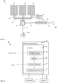
- an exemplary system 100 comprises one or more power converters 10, a plurality of battery packs 20, and a controller 60.
- the number of each component and the configuration in FIG. 1 are for illustration only.
- the system may have any suitable number of each component in any suitable combination or configuration.
- Each power converter 10 is coupled with at least one of the plurality of battery packs 20, and is configured to convert direct current (DC) from a battery pack to alternating current (AC) or vice versa.
- the power converter 10 can be also called as power conversion system (PCS) or an inverter.
- the controller 60 is coupled to the plurality of battery packs 20 and the one or more power converters 10.
- the system may also include more than one controller 60, and each controller 60 is coupled to a plurality of battery packs 20.
- the controller 60 may be coupled to the plurality of battery packs 20 directly or indirectly.
- the exemplary system 100 may optionally further comprise one or more battery power management unit (BPMU), which can be also called battery management unit (BMU).
- BPMU battery power management unit
- BMU battery management unit
- Each BPMU 30 may be connected with one or more battery packs 20, and is configured to monitor the one or more battery packs 20 and provide characteristic data of the one or more battery packs 20 to the controller 60.
- the controller 60 is configured to read the data from each battery pack 20. This may be done through each respective BPMU 30 connected with each battery pack.
- the plurality of battery packs 20 are heterogeneous battery packs, which can be selected from new batteries, second-use electric vehicle (EV) batteries, or combinations thereof.
- the plurality of battery packs 20 are connected in parallel, in series, or in a combination thereof. In some embodiments, the plurality of battery packs 20 are connected in parallel. No series connection between battery packs eliminates circulating currents and losses.
- the plurality of battery packs 20 are connected in a parallel configuration.
- the plurality of battery packs 20 are second-use (i.e. used) electric vehicle (EV) batteries.
- the used EV batteries can be directly utilized in the system, without pre-selection or dismantling.
- Each battery pack 20 comprises a battery or batteries.
- Each battery packs 20 may include an internal battery management unit (BMU), and an internal inverter. EV battery packs 20 are removed from vehicles and are not disassembled into modules. Simple tests may be done on these EV battery packs 20 to verify their SOH.
- BMU battery management unit
- Simple tests may be done on these EV battery packs 20 to verify their SOH.
- the exemplary system 100 is an electrical energy storage system.
- the controller 60 is configured to receive a total power demand provided from an upper level energy management system (EMS) 110 or calculated the total power demand based on input data received from the EMS.
- the controller 60 is configured to discharge power from the plurality of battery packs 20 in direct current to a grid or load 85 in alternating current, or vice versa.
- the exemplary system 100 can be used for discharging power from battery packs 20 to a grid 85, or for charging from the grid 85 to battery packs 20.
- Wire connection 12 may be used.
- the dotted lines 13 in FIG. 1 illustrates alternative power cables. Multiple power cable topologies may exist between the converter 10 and battery packs 20.
- the system 100 directly uses grid tied AC/DC converters 10 with flexibility in size expansion. No additional power conversion system is required for grid tied applications.
- the grid 85 is optional.
- the power can be discharged to other components, in which electrical power is needed.
- the controller 60 may be connected with other components in wire or wireless mode.
- the controller 60 may be connected with other components such as converter 10, BPMU 30 and EMS 110 via data cable or wireless connection 22.
- the BPMU 30 may be also connected with battery packs 20 via data cables or wireless connection 22.
- the controller 60 can work in a cloud-based mode.
- Each battery pack 20 may be connected to a power converter 10 (or independent DC port on a converter 10) through a set of automatic DC circuit breakers (not shown), which activate and control the connection between a battery pack 20 and the converter 10.
- the converter 10 controls whether or not to charge or discharge the single EV battery pack 20 by following the instructions from the controller 60.
- the controller 60 comprises one or more processors 62 and at least one tangible, non-transitory machine readable medium encoded with one or more programs configured to perform steps for controlling a discharging process of the system having the plurality of battery packs.
- the controller 60, the processor 62, and/or the program 74 may be an external device to the converter 10, or be an internal device inside the converter 10.
- the processor(s) 62 may include a central control 64, which includes a parameter input module 66, model module 68, a parameter control module 70, and information and instruction module 72.
- the parameter input module 66 coordinates with the battery packs 20, optionally BPMU 30 and HMI or EMS 110, to read the data from battery packs 20 and power demand from HMI or EMS 110.
- the parameter input module 66 also coordinates with each power converter 10.
- the parameter control module 70 coordinates with each power converter 10 and each battery pack 20, and optionally with BPMU 30 and HMI or EMS 110 to control a process of discharging.
- the model module 68 is configured to perform a simulation based on the input parameters to provide information and instruction to the parameter control module 70 and the information and instruction module 72.
- the processors 62 may be optionally connected with one or more displays 76 for displaying the information and instructions from module 72 and to an operator.
- the controller 60 with the programs 74 and the processor 62 are configured to perform steps for discharging or charging as described herein. As described in FIG. 4 , in some embodiments, the controller 60 is configured to perform the steps described herein. These steps include: collecting characteristic data of each battery pack 20, and receiving or calculating a total power demand (D) needed to be dispatched from the system 100 or to be charged to the system 100 in a first time interval.
- the characteristic data of each battery pack 20 include, but are not limited to, a present voltage (V i ), state of charge (SOC;), a number of cells in each battery packs (Nc), a maximum voltage (V c max ) and a minimum voltage (V c min ) of a cell.
- the number of battery packs is represent as "n.”
- the subscript "i" represents battery packs from 1 to n.
- the total power demand (D) may be in Kilowatts.
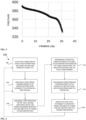
- Each battery pack 20 may have a maximum voltage (V max ) and a minimum voltage for discharge (V min ), which can be derived from a curve (e.g., FIG. 3 ) of voltage versus charge of each battery pack 20.
- Each cell may have a maximum voltage (V c max ) and a minimum voltage (V c min ).
- the maximum voltage (V max ) and a minimum voltage for discharge (V min ) of a battery pack are the number of cells in a battery pack times the maximum voltage (V c max ) and the minimum voltage (V c min ) of a cell.
- different cells have the same set of V c max and V c min . Sometimes average values of different cells are used. For example, in the Examples, the maximum voltage (V c max ) and the minimum voltage (V c min ) of a cell used are 4.2 volts and 3.5 volts, respectively.
- the steps further comprise assigning a first weighting factor (a) and a second weighting factor (b) for power assignment based on voltage and state of charge of each battery pack, respectively.
- a weighting factor a and b
- Each of the factors a and b is between 0 and 1, for example, in a range of from 0.01 to 0.99.
- the steps further comprise determining a respective power discharge or charge for each battery pack based on the present voltage (V i ), the state of charge (SOC;), the number of cells in each battery packs (Nci), the maximum voltage (V c max ) and the minimum voltage (V c min ) of a cell, the first weighting factor (a), the second weighting factor (b), and the total power demand (D).
- the controller 60 is configured to determine a respective power discharge or charge for each battery pack as follows.
- V i ′ V i / N ci ⁇ V c min / V c max ⁇ V c min
- a baseline SOC (SOC b ) is set for each of the plurality of battery packs.
- the term "when” used here is interchangeable with the term "if.”
- the steps further comprise calculating a voltage-charge combination factor (C i ) of each battery pack.
- a respective power discharge or charge (d i ) for each battery pack is then calculated.
- Sum (C i ) is a sum of the voltage-charge combination factor of (C i ) of each and every of the plurality of battery packs.
- a power share (in percentage) for discharge or charge of a respective battery pack is represented by a ratio of C i /Sum (C;).
- the controller 60 is configured to provide signals with instructions to the plurality of battery packs 20 and the one or more power converters for discharging power from or charging power to the plurality of battery packs 20 based on the respective power discharge or charge of each battery pack and/or keeping a certain battery pack idle.
- the controller 60 is also configured to repeat some or all the steps to re -determine the respective power discharge or charge for each battery pack in a second time interval after the first time interval ends.
- the time interval can be in any suitable ranges.
- the first and the second time intervals can be the same or different.
- the controller 60 can be configured to dynamically control discharging or charging of the plurality of battery packs by updating the respective power discharge or charge for each battery pack instantaneously with time.
- the present disclosure provides a controller 60 as described herein for controlling discharge of a system 100 comprising a plurality of battery packs 20.
- the controller 60 is configured to control discharge or charge of heterogeneous battery packs 20, for example, in an electrical energy storage system.
- the controller 60 is configured to discharge power from the plurality of battery packs 20 to a grid or load 85 or charge power to the plurality of battery packs 20.
- the controller 60 is configured to provide signals with instructions to the plurality of battery packs 20 and the one or more power converters 10 for discharging power from (or charging power to) the plurality of battery packs based on the respective discharge power of each battery pack and/or keeping a certain battery pack idle.
- the controller 60 is configured for controlling discharge or charge of heterogeneous battery packs 20, for example, in an electrical energy storage system.
- the controller 60 is configured to discharge power from the plurality of battery packs to a grid or load, or charge power from the grid or load to the plurality of battery packs.
- the present disclosure also provides a method 200 for controlling discharge or charge of a system 100 comprising a plurality of battery packs 20 through a controller 60 therein as described herein.
- the input parameter may include voltage, current and time.
- Charge or charge flow (Q) is calculated from the current flow and the time elapsed.
- the voltage has a unit of volt (v), and the charge flow has a unit of Amp* hour (Ah) or coulomb.
- Vmax is the voltage of such a battery pack when it is fully charged or it is at its maximum allowable charge level.
- Vmin is the voltage of such a battery pack when it is depleted of charge or it reaches its minimum allowable charge level.
- the curve of voltage versus charge can be empirically generated at constant level of discharge while monitoring the current flow over the discharge period until the voltage drops beyond a user-defined minimum limit (Vmin), shown by the vertical dotted line in FIG. 3 .
- Vmin user-defined minimum limit
- the current and the voltage follow the same or similar trend with increase in charging time.
- the curves of voltage versus charge are empirically generated at constant level of discharge while monitoring the current flow over the discharge period until the voltage drops beyond a user-defined minimum limit, shown by the intersection of the dotted vertical line with horizontal line from the y-axis.
- Different discharge rates may yield different voltage discharge curves for the same battery packs.
- a family of curves at different discharge rates can be provided for each respective battery pack 20, and can be used to track the voltage trajectory of the packs for a given dispatch episode.
- a technique such as extrapolation, interpolation, or averaging is used to get a representative curve.
- Vmax and Vmin are open circuit voltage specified by manufacturer or derived from predetermined voltage-charge curves. The range of from Vmin to Vmax may be in a range of from 400 volts to 1,000 volts.
- a voltage distribution parameter V* of a battery pack 20 having a present voltage (V) is defined as (V-Vmin)/(Vmax-Vmin).
- the voltage distribution parameter V* of a battery pack 20 and the voltage distribution parameter (V i ') for a cell may be in any suitable range, for example, in a range of from 50% to 95% in some embodiments.
- FIG. 4 illustrates an exemplary method 200 for controlling or managing discharge or charge of a plurality of battery packs 20 in a system 100 in accordance with some embodiments.
- the plurality of battery packs 20 are heterogeneous battery packs selected from new batteries, second-use electric vehicle (EV) batteries, or combinations thereof.
- the plurality of battery packs 20 are connected in parallel, in series, or in a combination thereof.
- the plurality of battery packs 20 are connected preferably in parallel.
- characteristic data of each battery pack 20 are collected.
- the characteristic data of each battery pack 20 include a present voltage (V i ), state of charge (SOC;), a number of cells in each battery packs (Nc), a maximum voltage (V c max ) and a minimum voltage (V c min ) of a cell.
- the minimum and maximum voltage of each battery pack 20 can be calculated according to the number of the cells in the respective pack and the configuration, in which the cells are arranged. For example, if maximum and minimum voltages of each cell are 4.2V and 3.5V, respectively, and a battery pack includes 144 cells, Vmax for the pack is 4.2 ⁇ 144 V and Vmin for such a battery pack is 3.5 ⁇ 144 V.
- a total power demand (D) needed to be dispatched from the system 100 or to be charged to the system in a first time interval is received by the controller 60.
- a total power demand may be received from EMS 110.
- the total power demand (D) in the first time interval may also be calculated by the controller 60 based on the information from the EMS 110.
- a first weighting factor (a) and a second weighting factor (b) for power assignment based on voltage and state of charge of each battery pack, respectively, are assigned.
- the sum of a and b is equal to 1.
- the weighing parameters a and b can be adjustable. For example, when a battery pack is relatively new, the value of b can be close to 1 and the value of a can be close to 0. As such a battery ages, the value of b will be adjusted to decrease and the value of a starts to increase correspondingly.
- a respective power discharge or charge (di) for each battery pack is determined.
- the respective power discharge or charge is calculated based on the present voltage (V i ), the state of charge (SOC;), the number of cells in each battery packs (Nci), the maximum voltage (V c max ) and the minimum voltage (V c min ) of a cell, the first weighting factor (a), the second weighting factor (b), and the total power demand (D).
- V i present voltage
- SOC state of charge
- Nci the number of cells in each battery packs
- V c max maximum voltage
- V c min the minimum voltage
- a respective power discharge or charge for each battery pack (di) is determined through steps including steps 212-220 as shown in FIG. 5 .
- the cells in one battery packs are the same, and share the same Vi'. Or the cells in one battery pack are averaged out to provide one value of V i .
- a baseline SOC (SOC b ) is set or selected for each of the plurality of battery packs.
- the baseline SOC (SOC b ) for each of the plurality of battery packs can be any suitable range, for example, from 10 % to 90%, from 20% to 80%, from 30% to 70%, from 20% to 60%, or from 40% to 60% (e.g., 25%, 30%, 35%, 40%, 45%, 50%, 55%, 60%).
- the baseline SOC is established to ensure each battery pack having a minimum charge during a discharging or charging process, so the battery packs 20 are protected.
- Sum (C i ) is a sum of the voltage-charge combination factor of (C i ) of each and every of the plurality of battery packs including from 1 to n.
- a power share (in percentage) for discharge or charge of a respective battery pack is represented by a ratio of C; /Sum (C i ).
- the plurality of battery packs discharge to meet a requirement for the power demand (D)
- the controller 60 provide signals with instructions to the plurality of battery packs 20 and the one or more power converters for discharging power from or charging power to the plurality of battery packs 20 based on the respective power discharge or charge of each battery pack and/or keeping a certain battery pack idle. The discharging or charging process occurs.
- Power from the plurality of battery packs 20 is discharged or the power will be charged to the battery packs 20 according to the instructions. After each process, for each battery pack, an alternate curve of voltage versus charge might be generated. Sometimes the characteristic data of each battery pack may be the same.
- the time interval can be in any suitable ranges.
- the first and the second time intervals can be the same or different.
- the first and the second time intervals are in any range, for example, from 10 second to 2 hours, from 1 minute to 1 hour, and can be the same or different.
- the interval can be defined by a user.
- each time interval may be 1 minute, 2 minutes, 5 minutes, 10 minutes, 15 minutes, 20 minutes, 25 minutes, 30 minutes, 35 minutes, 60 minutes, or any suitable time period.
- the controller 60 can be configured to dynamically control discharging or charging of the plurality of battery packs by up dating the respective power discharge or charge for each battery pack instantaneously with time.
- the controller 60 re-assigns power discharge or charge for the plurality of battery packs 20 after the time interval ends to a battery pack, by repeating some or all of the steps including steps 202, 204, 206, 210 (including steps 212, 214, 216, 218, and 220), and 230.
- the repeated process goes back to and starts from step 202.
- the repeated process goes back to and starts from step 204.
- the discharging or charging process of the plurality of battery packs can also be dynamically controlled by updating the respective power discharge or charge of each battery pack instantaneously with time.
- the time interval can be very short or minimal.
- the methods provided in the present disclosure utilize a plurality of heterogeneous battery packs to provide a consistent and long-lasting dispatch profiles to satisfy the dispatch requirement for discharging or charging from the EMS.
- the managed throughput leads to improved life and performance for an energy storage system.
- the system 100 includes a heterogeneous battery packs 20 integrated with bidirectional converter (or inverter) 10 connected to the grid or microgrid 85 that can be dispatched remotely or locally using this intelligent algorithm running in local or cloud-based controller 60.
- the algorithm requires prior knowledge of the voltage-charge curves, which can be acquired during commissioning and subsequently updated as the battery packs age or wear out due to use/disuse.
- the system, the controller, and the method provided in the present disclosure offer many advantages. For example, a variety of battery packs such as used EV battery packs having different quality can be used. No pre-selection or dismantle of the battery packs are needed. The system, the controller, and the method extend the life of some or all battery packs, and they also offer flexibility in maintaining and upgrading the system as well.
- An exemplary energy storage system 100 includes 9 battery packs, each of which is connected with a single inverter.
- the battery packs can be discharged maximum at 0.5C and charged at 0.5C.
- the capacities and voltage characteristics are different among the battery packs, so their recommended/allowable maximum charge and discharge rates are different. It is assumed that the battery packs have the characteristics data as shown in Table 1. Table 1. Pack No.
- the voltage Vi and SOCi are the instantaneous measured voltage and state of charge of the individual battery packs.
- Each battery pack is assumed to be made of 144 individual cells. It is desired that each cell is operated in the range of 4.2V and 3V. So the maximum voltage (V c max ) and the minimum voltage (V c min ) of a cell is 4.2V and 3V, respectively.
- dispatch power (D) of -17.56 kW is required by the energy storage system within a time interval, for example, of 15 minutes.
- the negative sign of the dispatch power means that discharge is needed.
- Table 2 shows the parameters calculated in the method, including the voltage distribution parameter (V i ') for a cell, the variation of state of charge (SOC;'), the voltage-charge combination factor (C i ) of each battery pack, and the respective power discharge or charge (d i ) for each battery pack.
- V i ' the voltage distribution parameter
- SOC state of charge
- C i the voltage-charge combination factor
- V i ' SOC i ' C i d i 0.13 0.33 0.24 -1.86 2 0.08 -0.05 0.01 -0.08 3 0.65 -0.08 0.25 -1.93 4 0.79 0.36 0.56 -4.31 5 0.26 0.23 0.25 -1.90 6 0.21 0.18 0.19 -1.50 7 0.25 -0.23 -0.01 0.09 8 0.40 0.58 0.50 -3.84 9 0.63 0.01 0.29 -2.24
- SOC b is an input parameter to the algorithm where it is the desired baseline SOC for each pack. For illustration purposes, it is chosen as 25%.
- the sign for C i of battery pack No. 7 is different from those of the other packs. This implies that if the overall dispatch required is discharging at the required level, in this particular example one of the packs will be charging.
- the sign for the respective power discharge or charge (d i ) of battery pack No. 7 is positive (meaning charged) while the other battery packs discharge power.
- the total power dispatch is -17.56 kW. All the packs discharge except battery pack No. 7 is charged at 0.09 kW in this time interval.
- the present disclosure also at least one tangible, non-transitory machine readable medium encoded with the one or more programs as described herein.
- the methods and system described herein may be at least partially embodied in the form of computer-implemented processes and apparatus for practicing those processes.
- the disclosed methods may also be at least partially embodied in the form of tangible, non-transient machine readable storage media encoded with computer program code.
- the media may include, for example, RAMs, ROMs, CD-ROMs, DVD-ROMs, BD-ROMs, hard disk drives, flash memories, or any other non-transient machine-readable storage medium, or any combination of these mediums, wherein, when the computer program code is loaded into and executed by a computer, the computer becomes an apparatus for practicing the method.
- the methods may also be at least partially embodied in the form of a computer into which computer program code is loaded and/or executed, such that, the computer becomes an apparatus for practicing the methods.
- the computer program code segments configure the processor to create specific logic circuits.
- the methods may alternatively be at least partially embodied in a digital signal processor formed of application specific integrated circuits for performing the methods.
- the computer or the control unit may be operated remotely using a cloud based system.
Landscapes
- Engineering & Computer Science (AREA)
- Power Engineering (AREA)
- Transportation (AREA)
- Mechanical Engineering (AREA)
- Life Sciences & Earth Sciences (AREA)
- Sustainable Development (AREA)
- Sustainable Energy (AREA)
- Health & Medical Sciences (AREA)
- General Health & Medical Sciences (AREA)
- Medical Informatics (AREA)
- Charge And Discharge Circuits For Batteries Or The Like (AREA)
- Secondary Cells (AREA)
Applications Claiming Priority (2)
| Application Number | Priority Date | Filing Date | Title |
|---|---|---|---|
| US17/506,153 US20230117104A1 (en) | 2021-10-20 | 2021-10-20 | Controller and method for balancing discharge or charge of battery packs in energy storage system |
| PCT/CN2022/080200 WO2023065588A1 (zh) | 2021-10-20 | 2022-03-10 | 用于平衡储能系统中电池组放电或充电的控制器和方法 |
Publications (1)
| Publication Number | Publication Date |
|---|---|
| EP4422014A1 true EP4422014A1 (en) | 2024-08-28 |
Family
ID=85982540
Family Applications (1)
| Application Number | Title | Priority Date | Filing Date |
|---|---|---|---|
| EP22882213.6A Pending EP4422014A1 (en) | 2021-10-20 | 2022-03-10 | Controller and method for balancing discharge or charge of battery pack in energy storage system |
Country Status (4)
| Country | Link |
|---|---|
| US (1) | US20230117104A1 (zh) |
| EP (1) | EP4422014A1 (zh) |
| CN (1) | CN115995861A (zh) |
| WO (1) | WO2023065588A1 (zh) |
Families Citing this family (3)
| Publication number | Priority date | Publication date | Assignee | Title |
|---|---|---|---|---|
| US20220302724A1 (en) * | 2021-03-16 | 2022-09-22 | China Energy Investment Corporation Limited | Battery management unit, energy storage system comprising the same, and methods of using the same |
| US20230305064A1 (en) * | 2022-03-28 | 2023-09-28 | Ratnesh Kumar Sharma | Systems and methods for managing diverse batteries |
| CN116961177B (zh) * | 2023-07-20 | 2024-03-08 | 安徽大学 | 一种基于调度场算法的电池组最大可用容量利用方法 |
Family Cites Families (7)
| Publication number | Priority date | Publication date | Assignee | Title |
|---|---|---|---|---|
| WO2012026108A1 (en) * | 2010-08-23 | 2012-03-01 | Sanyo Electric Co., Ltd. | Power management system |
| JP5704156B2 (ja) * | 2012-12-25 | 2015-04-22 | 株式会社デンソー | 蓄電池システム |
| WO2014187487A1 (en) * | 2013-05-23 | 2014-11-27 | Caterva Gmbh | A system for providing a primary control power for a power grid |
| CN103762624B (zh) * | 2013-12-28 | 2016-11-23 | 华为技术有限公司 | 一种电池管理方法及装置 |
| KR101684543B1 (ko) * | 2015-06-19 | 2016-12-20 | 현대자동차 주식회사 | 하이브리드 차량의 운전 모드 제어 시스템 및 그 방법 |
| US11691518B2 (en) * | 2017-07-21 | 2023-07-04 | Quantumscape Battery, Inc. | Predictive model for estimating battery states |
| CN108365632A (zh) * | 2018-04-08 | 2018-08-03 | 华中科技大学 | 一种基于储能电池的电力系统及运行方法 |
-
2021
- 2021-10-20 US US17/506,153 patent/US20230117104A1/en active Pending
-
2022
- 2022-03-10 WO PCT/CN2022/080200 patent/WO2023065588A1/zh active Application Filing
- 2022-03-10 CN CN202210233246.8A patent/CN115995861A/zh active Pending
- 2022-03-10 EP EP22882213.6A patent/EP4422014A1/en active Pending
Also Published As
| Publication number | Publication date |
|---|---|
| CN115995861A (zh) | 2023-04-21 |
| WO2023065588A1 (zh) | 2023-04-27 |
| US20230117104A1 (en) | 2023-04-20 |
Similar Documents
| Publication | Publication Date | Title |
|---|---|---|
| EP4422014A1 (en) | Controller and method for balancing discharge or charge of battery pack in energy storage system | |
| KR101725701B1 (ko) | 복수 전지를 갖는 이차 전지 시스템 및 충방전 전력 또는 전류의 배분 방법 | |
| KR101084216B1 (ko) | 에너지 저장 시스템 및 이의 제어 방법 | |
| US9653924B2 (en) | Battery system | |
| EP3503282A1 (en) | Quick charging method for parallel battery pack, and related device | |
| EP2566007B1 (en) | Cell balancing device and method | |
| EP4054051A1 (en) | Energy storage system and battery management method | |
| US20130187465A1 (en) | Power management system | |
| EP4422019A1 (en) | Controller for managing charging or discharging of heterogeneous battery pack, system, and method | |
| KR20130066283A (ko) | 배터리 시스템의 시뮬레이션 장치 | |
| US11799140B2 (en) | Controller for energy storage, system comprising the same, and methods of using the same | |
| US11652357B1 (en) | Controller, system and method for controlling discharge of heterogeneous battery packs | |
| KR20200048913A (ko) | 폐배터리 기반의 독립형 가정용 에너지 저장 시스템 | |
| Thomas et al. | Electric vehicle integration to distribution grid ensuring quality power exchange | |
| US20220344959A1 (en) | Voltage-biased controller, system and method for controlling discharge of heterogeneous battery packs | |
| JP2012249500A (ja) | 電力系統管理システム及び電力系統の管理方法 | |
| CN115250000A (zh) | 用于控制电池组放电的系统、方法、控制器及介质 | |
| KR101689017B1 (ko) | 마이크로그리드 내 다수 bess의 퍼지 드룹 제어 시스템 및 방법 | |
| US20240201277A1 (en) | Energy storage system | |
| Makibar Puente et al. | Characterisation and efficiency test of a Li-ion energy storage system for PV systems | |
| US20220302724A1 (en) | Battery management unit, energy storage system comprising the same, and methods of using the same | |
| CN111354991B (zh) | 一种电池养护系统、方法及能在线养护电池的微电网系统 | |
| CN110707679B (zh) | 电压控制方法及光伏供电装置、系统 | |
| WO2013042712A1 (ja) | 電池ブロックの充放電制御装置 |
Legal Events
| Date | Code | Title | Description |
|---|---|---|---|
| STAA | Information on the status of an ep patent application or granted ep patent |
Free format text: STATUS: THE INTERNATIONAL PUBLICATION HAS BEEN MADE |
|
| PUAI | Public reference made under article 153(3) epc to a published international application that has entered the european phase |
Free format text: ORIGINAL CODE: 0009012 |
|
| STAA | Information on the status of an ep patent application or granted ep patent |
Free format text: STATUS: REQUEST FOR EXAMINATION WAS MADE |
|
| 17P | Request for examination filed |
Effective date: 20240425 |
|
| AK | Designated contracting states |
Kind code of ref document: A1 Designated state(s): AL AT BE BG CH CY CZ DE DK EE ES FI FR GB GR HR HU IE IS IT LI LT LU LV MC MK MT NL NO PL PT RO RS SE SI SK SM TR |