EP4422013A1 - System und verfahren zur entkopplung von antriebsstrangbezogenen leistungsschwankungen einer wechselrichterbasierten ressource aus in das stromnetz injizierter aktiver leistung - Google Patents
System und verfahren zur entkopplung von antriebsstrangbezogenen leistungsschwankungen einer wechselrichterbasierten ressource aus in das stromnetz injizierter aktiver leistung Download PDFInfo
- Publication number
- EP4422013A1 EP4422013A1 EP24159163.5A EP24159163A EP4422013A1 EP 4422013 A1 EP4422013 A1 EP 4422013A1 EP 24159163 A EP24159163 A EP 24159163A EP 4422013 A1 EP4422013 A1 EP 4422013A1
- Authority
- EP
- European Patent Office
- Prior art keywords
- inverter
- feedback signals
- voltage
- voltage feedback
- based resource
- Prior art date
- Legal status (The legal status is an assumption and is not a legal conclusion. Google has not performed a legal analysis and makes no representation as to the accuracy of the status listed.)
- Pending
Links
Images


Classifications
-
- H—ELECTRICITY
- H02—GENERATION; CONVERSION OR DISTRIBUTION OF ELECTRIC POWER
- H02J—ELECTRIC POWER NETWORKS; CIRCUIT ARRANGEMENTS OR SYSTEMS FOR SUPPLYING OR DISTRIBUTING ELECTRIC POWER; SYSTEMS FOR STORING ELECTRIC ENERGY
- H02J3/00—Circuit arrangements for AC mains or AC distribution networks
- H02J3/002—Flicker reduction, e.g. compensation of flicker introduced by non-linear load
-
- H—ELECTRICITY
- H02—GENERATION; CONVERSION OR DISTRIBUTION OF ELECTRIC POWER
- H02J—ELECTRIC POWER NETWORKS; CIRCUIT ARRANGEMENTS OR SYSTEMS FOR SUPPLYING OR DISTRIBUTING ELECTRIC POWER; SYSTEMS FOR STORING ELECTRIC ENERGY
- H02J3/00—Circuit arrangements for AC mains or AC distribution networks
- H02J3/001—Arrangements for handling faults or abnormalities, e.g. emergencies or contingencies
- H02J3/0014—Arrangements for handling faults or abnormalities, e.g. emergencies or contingencies for preventing or reducing power oscillations in networks
-
- F—MECHANICAL ENGINEERING; LIGHTING; HEATING; WEAPONS; BLASTING
- F03—MACHINES OR ENGINES FOR LIQUIDS; WIND, SPRING, OR WEIGHT MOTORS; PRODUCING MECHANICAL POWER OR A REACTIVE PROPULSIVE THRUST, NOT OTHERWISE PROVIDED FOR
- F03D—WIND MOTORS
- F03D7/00—Controlling wind motors
- F03D7/02—Controlling wind motors the wind motors having rotation axis substantially parallel to the air flow entering the rotor
- F03D7/0272—Controlling wind motors the wind motors having rotation axis substantially parallel to the air flow entering the rotor by measures acting on the electrical generator
-
- F—MECHANICAL ENGINEERING; LIGHTING; HEATING; WEAPONS; BLASTING
- F03—MACHINES OR ENGINES FOR LIQUIDS; WIND, SPRING, OR WEIGHT MOTORS; PRODUCING MECHANICAL POWER OR A REACTIVE PROPULSIVE THRUST, NOT OTHERWISE PROVIDED FOR
- F03D—WIND MOTORS
- F03D7/00—Controlling wind motors
- F03D7/02—Controlling wind motors the wind motors having rotation axis substantially parallel to the air flow entering the rotor
- F03D7/028—Controlling wind motors the wind motors having rotation axis substantially parallel to the air flow entering the rotor controlling wind motor output power
- F03D7/0284—Controlling wind motors the wind motors having rotation axis substantially parallel to the air flow entering the rotor controlling wind motor output power in relation to the state of the electric grid
-
- F—MECHANICAL ENGINEERING; LIGHTING; HEATING; WEAPONS; BLASTING
- F03—MACHINES OR ENGINES FOR LIQUIDS; WIND, SPRING, OR WEIGHT MOTORS; PRODUCING MECHANICAL POWER OR A REACTIVE PROPULSIVE THRUST, NOT OTHERWISE PROVIDED FOR
- F03D—WIND MOTORS
- F03D7/00—Controlling wind motors
- F03D7/02—Controlling wind motors the wind motors having rotation axis substantially parallel to the air flow entering the rotor
- F03D7/0298—Controlling wind motors the wind motors having rotation axis substantially parallel to the air flow entering the rotor to prevent, counteract or reduce vibrations
-
- F—MECHANICAL ENGINEERING; LIGHTING; HEATING; WEAPONS; BLASTING
- F03—MACHINES OR ENGINES FOR LIQUIDS; WIND, SPRING, OR WEIGHT MOTORS; PRODUCING MECHANICAL POWER OR A REACTIVE PROPULSIVE THRUST, NOT OTHERWISE PROVIDED FOR
- F03D—WIND MOTORS
- F03D9/00—Adaptations of wind motors for special use; Combinations of wind motors with apparatus driven thereby; Wind motors specially adapted for installation in particular locations
- F03D9/20—Wind motors characterised by the driven apparatus
- F03D9/25—Wind motors characterised by the driven apparatus the apparatus being an electrical generator
-
- H—ELECTRICITY
- H02—GENERATION; CONVERSION OR DISTRIBUTION OF ELECTRIC POWER
- H02J—ELECTRIC POWER NETWORKS; CIRCUIT ARRANGEMENTS OR SYSTEMS FOR SUPPLYING OR DISTRIBUTING ELECTRIC POWER; SYSTEMS FOR STORING ELECTRIC ENERGY
- H02J3/00—Circuit arrangements for AC mains or AC distribution networks
- H02J3/38—Arrangements for feeding a single network from two or more generators or sources in parallel; Arrangements for feeding already energised networks from additional generators or sources in parallel
- H02J3/381—Dispersed generators
-
- H—ELECTRICITY
- H02—GENERATION; CONVERSION OR DISTRIBUTION OF ELECTRIC POWER
- H02J—ELECTRIC POWER NETWORKS; CIRCUIT ARRANGEMENTS OR SYSTEMS FOR SUPPLYING OR DISTRIBUTING ELECTRIC POWER; SYSTEMS FOR STORING ELECTRIC ENERGY
- H02J3/00—Circuit arrangements for AC mains or AC distribution networks
- H02J3/38—Arrangements for feeding a single network from two or more generators or sources in parallel; Arrangements for feeding already energised networks from additional generators or sources in parallel
- H02J3/46—Controlling the sharing of generated power between the generators, sources or networks
- H02J3/48—Controlling the sharing of active power
-
- F—MECHANICAL ENGINEERING; LIGHTING; HEATING; WEAPONS; BLASTING
- F05—INDEXING SCHEMES RELATING TO ENGINES OR PUMPS IN VARIOUS SUBCLASSES OF CLASSES F01-F04
- F05B—INDEXING SCHEME RELATING TO WIND, SPRING, WEIGHT, INERTIA OR LIKE MOTORS, TO MACHINES OR ENGINES FOR LIQUIDS COVERED BY SUBCLASSES F03B, F03D AND F03G
- F05B2270/00—Control
- F05B2270/10—Purpose of the control system
- F05B2270/103—Purpose of the control system to affect the output of the engine
- F05B2270/1033—Power (if explicitly mentioned)
-
- F—MECHANICAL ENGINEERING; LIGHTING; HEATING; WEAPONS; BLASTING
- F05—INDEXING SCHEMES RELATING TO ENGINES OR PUMPS IN VARIOUS SUBCLASSES OF CLASSES F01-F04
- F05B—INDEXING SCHEME RELATING TO WIND, SPRING, WEIGHT, INERTIA OR LIKE MOTORS, TO MACHINES OR ENGINES FOR LIQUIDS COVERED BY SUBCLASSES F03B, F03D AND F03G
- F05B2270/00—Control
- F05B2270/30—Control parameters, e.g. input parameters
- F05B2270/337—Electrical grid status parameters, e.g. voltage, frequency or power demand
-
- H—ELECTRICITY
- H02—GENERATION; CONVERSION OR DISTRIBUTION OF ELECTRIC POWER
- H02J—ELECTRIC POWER NETWORKS; CIRCUIT ARRANGEMENTS OR SYSTEMS FOR SUPPLYING OR DISTRIBUTING ELECTRIC POWER; SYSTEMS FOR STORING ELECTRIC ENERGY
- H02J2101/00—Supply or distribution of decentralised, dispersed or local electric power generation
- H02J2101/20—Dispersed power generation using renewable energy sources
- H02J2101/28—Wind energy
Definitions
- the present disclosure relates in general to inverter-based resources, and more particularly to systems and methods for decoupling drivetrain related power oscillations of an inverter-based resource from active power injected into the electrical grid.
- Power generating assets may take a variety of forms and rely on renewable and/or nonrenewable sources of energy. Those power generating assets relying on renewable sources of energy may generally be considered one of the cleanest, most environmentally friendly energy sources presently available.
- wind turbines have gained increased attention in this regard.
- a modern wind turbine typically includes a tower, a generator, a gearbox, a nacelle, and one or more rotor blades.
- the nacelle includes a rotor coupled to the gearbox and to the generator.
- the rotor and the gearbox are mounted on a bedplate support frame located within the nacelle.
- the rotor blades capture kinetic energy of wind using known airfoil principles.
- the rotor blades transmit the kinetic energy in the form of rotational energy so as to turn a shaft coupling the rotor blades to the gearbox, or if the gearbox is not used, directly to the generator.
- the generator then converts the mechanical energy to electrical energy and the electrical energy may be transmitted to a converter and/or a transformer housed within the tower and subsequently deployed to a utility grid.
- Modern wind power generation systems typically take the form of a wind farm having multiple wind turbine generators that are operable to supply power to a transmission system providing power to an electrical grid.
- Wind turbines can be distinguished in two types: fixed speed and variable speed turbines.
- variable speed wind turbines are controlled as current sources connected to an electrical grid.
- the variable speed wind turbines rely on a grid frequency detected by a phase locked loop (PLL) as a reference and inject a specified amount of current into the grid.
- PLL phase locked loop
- the conventional current source control of the wind turbines is based on the assumptions that the grid voltage waveforms are fundamental voltage waveforms with fixed frequency and magnitude and that the penetration of wind power into the grid is low enough so as to not cause disturbances to the grid voltage magnitude and frequency.
- the wind turbines simply inject the specified current into the grid based on the fundamental voltage waveforms.
- Modern day wind turbine generators utilize grid-connected power converters to achieve certain special dynamic control functions (in addition to the primary control functions of regulating speed and power), such as damping drivetrain torsional oscillations and damping tower oscillations. These control functions change the active power injected into the grid at a particular frequency.
- the power oscillation components are usually at a known frequency dictated by the dimensions and physics of the wind turbine.
- These control functions are practical since grid-forming resources (mostly synchronous machines) are generally abundantly available in most applications such that these other resources can accommodate the change in active power injected by the wind turbine generators.
- the present disclosure is directed to a method for decoupling a mechanical drivetrain resonance mode of an inverter-based resource from the external electrical system.
- the inverter-based resource has a power converter, a generator, and an energy buffer.
- the method includes receiving, via a controller, one or more voltage feedback signals at a node between the inverter-based resource and the external electrical system.
- the method also includes filtering, via the controller, the one or more voltage feedback signals to extract changes in a voltage at a frequency associated with the drivetrain resonance mode.
- the method includes determining, via the controller, at least one current command or power command based on the filtered one or more voltage feedback signals.
- the method includes controlling the power converter according to the at least one current command and controlling the energy buffer according to the power command so as to reduce or eliminate the changes in the voltage at the frequency associated with the drivetrain resonance mode.
- the present disclosure is directed to an inverter-based resource connected to an electrical grid.
- the inverter-based resource includes a generator, a power converter coupled to the generator, and a controller having at least one processor configured to perform a plurality of operations.
- the plurality of operations includes receiving one or more voltage feedback signals at a node between the inverter-based resource and the external electrical system, filtering the one or more voltage feedback signals to extract changes in voltage at a frequency associated with the drivetrain resonance mode, determining at least one current command or power command based on the filtered one or more voltage feedback signals, and controlling the power converter according to the at least one current command and controlling the energy buffer according to the power command so as to reduce or eliminate the changes in the voltage at the frequency associated with the drivetrain resonance mode.
- first, second, and third may be used interchangeably to distinguish one component from another and are not intended to signify location or importance of the individual components.
- Coupled refers to both direct coupling, fixing, or attaching, as well as indirect coupling, fixing, or attaching through one or more intermediate components or features, unless otherwise specified herein.
- Approximating language is applied to modify any quantitative representation that could permissibly vary without resulting in a change in the basic function to which it is related. Accordingly, a value modified by a term or terms, such as “about”, “approximately”, and “substantially”, are not to be limited to the precise value specified. In at least some instances, the approximating language may correspond to the precision of an instrument for measuring the value, or the precision of the methods or machines for constructing or manufacturing the components and/or systems. For example, the approximating language may refer to being within a 10 percent margin.
- the present disclosure is directed to a system and method for decoupling drivetrain-related power oscillations of an inverter-based resource (that are driven by a mechanical drivetrain resonance or forced oscillation mode within an inverter-based resource) from the active power injected into the external electrical system.
- the inverter-based resource can manage loading on the drivetrain independent of the external electrical system conditions or topology.
- the inverter-based resource may be a wind turbine power system, a solar power system, a hydro-generator, or combinations thereof.
- the system and method of the present disclosure is also configured to decouple background electrical system oscillations caused by other assets connected to the external electrical system from the inverter-based resource, thereby decoupling the inverter-based resource and the external electrical system for certain types of oscillation modes.
- the external electrical system may be the bulk power system (e.g., the grid), a microgrid, or an electrical island in which one or more of the inverter-based resources are one of the primary generators within the network and electrical power flow is dominated by local loads.
- the inverter-based resource includes an energy buffer that is used to decouple power oscillations from the inverter-based resource from the total power output of the inverter-based resource.
- the power oscillations into the grid can be significantly reduced or eliminated by being absorbed by the energy buffer.
- the power rating of the energy buffer may be relatively small with respect to the inverter-based resource rating (e.g., from about 5% to about 10% of the rating).
- the energy buffer may include a battery energy storage device, one or more capacitors, or a resistive element (such as a dynamic brake), or combinations thereof.
- the energy buffer is controlled in such a way to create a "stiff" terminal voltage at predetermined frequencies associated with a mechanical resonance mode of the IBR. By creating this stiff voltage, the change in power caused by the inverter-based resource can be absorbed by the energy buffer.
- any oscillations in grid voltage magnitude, frequency, or angle at the predetermined frequency would be decoupled from the inverter-based resource, thereby buffering the inverter-based resource from any background oscillations in the grid itself or from other grid-forming or grid-following devices connected nearby. This is particularly important for grid-forming inverter-based resources, where active power generated is sensitive to these grid oscillations.
- the systems and methods of the present disclosure employ an algorithm for creating a stiff voltage at the inverter-based resource terminals at certain predetermined frequencies.
- the algorithm is configured to receive and filter one or more voltage feedback signals relating to a voltage at a frequency associated with the drivetrain resonance mode to extract changes in the voltage at the frequency associated with the drivetrain resonance mode.
- the algorithm is configured to determine at least one shunt current command or shunt power command based on the filtered one or more voltage feedback signals.
- the algorithm is further configured to control the power converter according to the current command and the energy buffer according to the power command so as to reduce or eliminate the changes in the voltage at the frequency associated with the drivetrain resonance mode.
- the algorithm includes receiving x and y voltage feedbacks calculated based on abc feedback signals and synchronous reference frame transformation.
- the voltage feedbacks can then be filtered, e.g., via a high pass filter, to remove direct current (DC) components associated with fundamental frequency.
- the algorithm includes calculating an angle rotating at a desired pre-determined frequency associated with the inverter-based resource.
- the algorithm is configured to rotate the filtered voltage feedback to a reference frame rotating at the desired pre-determined frequency. In this reference frame, components of the terminal voltage oscillating at the desired pre-determined frequency appear as DC signals.
- the rotated voltage feedbacks may again be filtered, e.g., via a low pass filter to remove higher-frequency components not associated with frequency components of interest.
- the calculated voltage feedbacks can then be used in an integral controller, where the intended reference voltage at this frequency is set to zero (0).
- the output of the integral controller may be a shunt current injection need to drive the changes in voltage at the pre-determined frequency to zero.
- the algorithm includes rotating the desired current back to the synchronous reference frame. This rotation may also include a predetermined phase shift setting that can be tuned for the application.
- the algorithm is configured to calculate a change to a power command for the energy buffer and/or a change for a reactive current command to the power converter (e.g., particularly the line side converter in wind turbine applications).
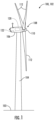
- FIG. 1 illustrates a perspective view of one embodiment of a inverter-based resource 100 according to the present disclosure.
- the inverter-based resource 100 may be configured as a wind turbine 102.
- the inverter-based resource 100 may, for example, be configured as a hydroelectric plant, a fossil fuel generator, and/or a hybrid power generating asset.
- the inverter-based resource 100 may generally include a tower 104 extending from a support surface 103, a nacelle 106 mounted on the tower 104, and a rotor 108 coupled to the nacelle 106.
- the rotor 108 includes a rotatable hub 110 and at least one rotor blade 112 coupled to and extending outwardly from the hub 110.
- the rotor 108 includes three rotor blades 112.
- the rotor 108 may include more or less than three rotor blades 112.
- Each rotor blade 112 may be spaced about the hub 110 to facilitate rotating the rotor 108 to enable kinetic energy to be transferred from the wind into usable mechanical energy, and subsequently, electrical energy.
- the hub 110 may be rotatably coupled to an electric generator 118 ( FIG. 2 ) of an electrical system 200 ( FIG. 2 ) positioned within the nacelle 106 to permit electrical energy to be produced.
- the wind turbine 102 may also include a controller 120 centralized within the nacelle 106.
- the controller 120 may be located within any other component of the wind turbine 102 or at a location outside the wind turbine 102. Further, the controller 120 may be communicatively coupled to any number of the components of the wind turbine 102 in order to control the components.
- the controller 120 may include a computer or other suitable processing unit.
- the controller 120 may include suitable computer-readable instructions that, when implemented, configure the controller 120 to perform various different functions, such as receiving, transmitting and/or executing wind turbine control signals.
- the inverter-based resource 100 may include at least one operational sensor 122.
- the operational sensor(s) 122 may be configured to detect a performance of the inverter-based resource 100, e.g., in response to the environmental condition.
- the operational sensor(s) 122 may be configured to monitor a plurality of electrical conditions, such as slip, stator voltage and current, rotor voltage and current, line-side voltage and current, DC-link charge and/or any other electrical condition of the inverter-based resource 100.
- the term "monitor” and variations thereof indicates that the various sensors of the inverter-based resource 100 may be configured to provide a direct measurement of the parameters being monitored or an indirect measurement of such parameters.
- the sensor(s) 122 described herein may, for example, be used to generate signals relating to the parameter being monitored, which can then be utilized by the controller 120 to determine a condition or response of the inverter-based resource 100.
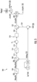
- the generator 118 may be coupled to the rotor 108 (e.g., either directly or through a gearbox 124) for producing electrical power from the rotational energy generated by the rotor 108.
- the electrical system 200 may include various components for converting the kinetic energy of the rotor 108 into an electrical output in an acceptable form to an electrical grid 202 via grid bus 204.
- the generator 118 may be a double-fed induction generator (DFIG) having a stator 206 and a generator rotor 208.
- DFIG double-fed induction generator
- the generator 118 may be coupled to a stator bus 210 and a power converter 220 via a rotor bus 212.
- the stator bus 210 may provide an output multiphase power (e.g., three-phase power) from a stator of the generator 118
- the rotor bus 212 may provide an output multiphase power (e.g., three-phase power) of the generator rotor 208 of the generator 118.
- the generator 118 may be coupled via the rotor bus 212 to a rotor side converter 222.
- the rotor side converter 222 may be coupled to a line-side converter 224 which, in turn, may be coupled to a line-side bus 214.
- the rotor side converter 222 and the line-side converter 224 may be configured for normal operating mode in a three-phase, pulse width modulation (PWM) arrangement using insulated gate bipolar transistors (IGBTs) Other suitable switching devices may be used, such as insulated gate commuted thyristors, MOSFETs, bipolar transistors, silicone-controlled rectifiers, and/or other suitable switching devices.
- PWM pulse width modulation
- IGBTs insulated gate bipolar transistors
- Other suitable switching devices may be used, such as insulated gate commuted thyristors, MOSFETs, bipolar transistors, silicone-controlled rectifiers, and/or other suitable switching devices.
- the rotor side converter 222 and the line-side converter 224 may be coupled via a DC link 226 across a DC link capacitor 228.
- the power converter 220 may include an energy buffer 238, such as a battery energy storage device, one or more capacitors, or a resistive element (such as a dynamic brake), or combinations thereof.
- the power converter 220 may be coupled to the controller 120 configured as a converter controller 230 to control the operation of the power converter 220.
- the converter controller 230 may send control commands to the rotor side converter 222 and the line-side converter 224 to control the modulation of switching elements used in the power converter 220 to establish a desired generator torque setpoint and/or power output.
- the electrical system 200 may, in an embodiment, include a transformer 216 coupling the inverter-based resource 100 to the electrical grid 202 (or another type of electrical system, such as a microgrid or electrical island with loads).
- the transformer 216 may, in an embodiment, be a three-winding transformer which includes a high voltage (e.g., greater than 12 KVAC) primary winding 217.
- the high voltage primary winding 217 may be coupled to the electrical grid 179.
- the transformer 216 may also include a medium voltage (e.g., 6 KVAC) secondary winding 218 coupled to the stator bus 210 and a low voltage (e.g., 575 VAC, 690 VAC, etc.) auxiliary winding 219 coupled to the line bus 214.
- a medium voltage (e.g., 6 KVAC) secondary winding 218 coupled to the stator bus 210 and a low voltage (e.g., 575 VAC, 690 VAC, etc.) auxiliary winding 219 coupled to the line bus 214.
- the transformer 216 can be a three-winding transformer as depicted, or alternatively, may be a two-winding transformer having only the primary winding 217 and the secondary winding 218; may be a four-winding transformer having the primary winding 217, the secondary winding 218, the auxiliary winding 219, and an additional auxiliary winding; or may have any other suitable number of windings.
- the electrical system 200 may include various protective features (e.g., circuit breakers, fuses, contactors, and other devices) to control and/or protect the various components of the electrical system 200.
- the electrical system 200 may, in an embodiment, include a grid circuit breaker 232, a stator bus circuit breaker 234, and/or a line bus circuit breaker 236.
- the circuit breaker(s) 232, 234, 236 of the electrical system 200 may connect or disconnect corresponding components of the electrical system 200 when a condition of the electrical system 200 approaches a threshold (e.g., a current threshold and/or an operational threshold) of the electrical system 200.
- a threshold e.g., a current threshold and/or an operational threshold
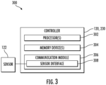
- the controller 300 may be the turbine controller 120 or the converter controller 230.
- the controller 120 includes one or more processor(s) 302 and associated memory device(s) 304 configured to perform a variety of computer-implemented functions (e.g., performing the methods, steps, calculations and the like and storing relevant data as disclosed herein).
- the controller 300 may also include a communications module 306 to facilitate communications between the controller 300, and the various components of the inverter-based resource 100.
- the communications module 306 may include a sensor interface 308 (e.g., one or more analog-to-digital converters) to permit signals transmitted from the sensor(s) 122 to be converted into signals that can be understood and processed by the processors 302.
- the sensor(s) 122 may be communicatively coupled to the communications module 306 using any suitable means.
- the sensor(s) 122 may be coupled to the sensor interface 308 via a wired connection.
- the sensor(s) 122 may be coupled to the sensor interface 308 via a wireless connection, such as by using any suitable wireless communications protocol known in the art.
- the term "processor” refers not only to integrated circuits referred to in the art as being included in a computer, but also refers to a controller, a microcontroller, a microcomputer, a programmable logic controller (PLC), an application specific integrated circuit, and other programmable circuits.
- the memory device(s) 304 may generally include memory element(s) including, but not limited to, computer readable medium (e.g., random access memory (RAM)), computer readable non-volatile medium (e.g., a flash memory), a floppy disk, a compact disc-read only memory (CD-ROM), a magneto-optical disk (MOD), a digital versatile disc (DVD) and/or other suitable memory elements.
- RAM random access memory
- CD-ROM compact disc-read only memory
- MOD magneto-optical disk
- DVD digital versatile disc
- Such memory device(s) 304 may generally be configured to store suitable computer-readable instructions that, when implemented by the processor(s) 302, configure the controller 300
- FIG. 4 a flow diagram of an embodiment of a method 400 for decoupling power oscillations from an inverter-based resource, such as inverter-based resource 100, connected to an electrical grid from a total power output of the inverter-based resource is illustrated according to the present disclosure.
- the method 400 may be implemented using, for instance, the controller 300 of the present disclosure discussed above with references to FIGS. 1-3 .
- FIG. 4 depicts steps performed in a particular order for purposes of illustration and discussion. Those of ordinary skill in the art, using the disclosures provided herein, will understand that various steps of the method 400, or any of the methods disclosed herein, may be adapted, modified, rearranged, performed simultaneously, or modified in various ways without deviating from the scope of the present disclosure.
- the method 400 includes receiving, via a controller, one or more voltage feedback signals at a node between the inverter-based resource and the external electrical system. As shown at (404), the method 400 includes filtering, via the controller, the one or more voltage feedback signals to extract changes in the voltage at the frequency associated with the drivetrain resonance mode. As shown at (406), the method 400 includes determining, via the controller, at least one current command or power command based on the filtered one or more voltage feedback signals. As shown at (408), the method 400 includes controlling the power converter according to the at least one current command and controlling the energy buffer according to the power command so as to reduce or eliminate the changes in the voltage at the frequency associated with the drivetrain resonance mode.
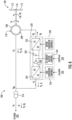
- FIG. 5 illustrates a schematic diagram of an embodiment of an algorithm 500 that can be implemented by the controller 300 for decoupling power oscillations from an inverter-based resource, such as inverter-based resource 100, connected to an electrical grid from a total power output of the inverter-based resource is illustrated according to the present disclosure.
- the algorithm 500 receives one or more inputs.
- the input(s) may include, for example, one or more voltage feedback signals 502 relating to a voltage at a frequency associated with the drivetrain resonance mode.
- the voltage feedback signal(s) 502 may include x and y voltage feedback signals (e.g., VMxyFbk). These x and y voltage feedbacks correspond to voltages at a node between the electrical system and the IBR, such as voltages at the primary winding of the IBR terminals or the secondary of the IBR terminals (or other node through which the entirety of output current of the IBR flows).
- the algorithm 500 is configured to calculate an angle 510 (e.g., DtdAng) rotating at a desired predetermined frequency (e.g., Fdtd) associated with the inverter-based resource 100.
- the algorithm 500 may include filtering the voltage feedback signal(s) to extract changes in the voltage at the frequency associated with the drivetrain resonance mode.
- the algorithm 500 may include filtering, via a first filter 504, the voltage feedback signal(s) 502 to remove one or more direct current (DC) components associated with a fundamental frequency.
- An output of the first filter 504 is represented as 506 in FIG. 5 .
- the first filter 504 may be a high-pass filter.
- the algorithm 500 is configured to filter, via a second filter 514, the voltage feedback signals 502 to remove high frequency components not associated with the desired predetermined frequency.
- An output of the second filter 514 is represented as 516 in FIG. 5 .
- the second filter 514 may be a low-pass filter.
- the algorithm 500 may also include rotating the filtered voltage feedback signals 506 (e.g., VMxyFbkHp) (i.e., after the first filter 504) from a synchronous reference frame to a reference frame rotating at the desired predetermined frequency based on the angle 510.
- the rotated signal is represented as 512 in FIG. 5 .
- components of a terminal voltage of the inverter-based resource 100 oscillating at the desired predetermined frequency appear as direct current (DC) signals.
- DC direct current
- the second filtering step can be employed after rotating the filtered voltage feedback signals 506 (e.g., VMxyFbkHp) from the synchronous reference frame to the reference frame rotating at the desired predetermined frequency based on the angle 510.
- filtered voltage feedback signals 506 e.g., VMxyFbkHp
- the algorithm 500 is further configured to determine at least one current command 532 ( ⁇ ILyDtd) or a power command 530 (e.g., ⁇ DcPCmd) based on the filtered voltage feedback signal(s) (represented by 516).
- the at least one current command or power command are intended to be reflected as shunt (or parallel) current/power injection at the node (or close to) for which the changes in voltage are being measured (for example, in a double-fed type generator, this can naturally be injected through the line-side converter since it injects a shunt current/power at a node between the external electrical system and the IBR generator).
- the algorithm 500 is configured to generate, via an integral controller 518, an output 520 using the rotated voltage feedback signal(s) 516.
- an intended reference voltage at the desired predetermined frequency (e.g., Fdtd) of the integral controller 518 is set to zero (0) and the output 520 of the integral controller 518 is the desired current associated with the desired predetermined frequency.
- the algorithm 500 is configured to determine the current command 532 ( ⁇ ILyDtd) or a power command 530 (e.g., ⁇ DcPCmd) based on the filtered one or more voltage feedback signals 516 by rotating the output 520 associated with the desired predetermined frequency back to the synchronous reference frame to generate a desired current 528 (e.g., ⁇ ILxyDtd). Accordingly, in such embodiments, the algorithm 500 is configured to determine the current command 532 ( ⁇ ILyDtd) or a power command 530 (e.g., ⁇ DcPCmd) based on the desired current 528.
- the algorithm 500 may also apply a predetermined phase shift setting 524 during the rotation at 522.
- the predetermined phase shift setting 524 may be determined as a function of the angle 510 and a drivetrain angle 526 (e.g., ⁇ dtd).
- the drivetrain angle 526 may be tuned at the design stage to give a reasonable decoupling of grid/drivetrain oscillations for a wide range of possible external electrical system types.
- this setting may be tuned on a site-by-site basis to optimize performance for the application.
- the current command 532 ( ⁇ ILyDtd) or a power command 530 (e.g., ⁇ DcPCmd) can be sent to an energy buffer control 534 and a line converter control 536, respectively, e.g., of the converter controller 230.
- the algorithm 500 may be selectively enabled upon detection of an island condition. Otherwise, in an embodiment, the algorithm 500 may operate continuously.
- the current command 532 ( ⁇ ILyDtd) or a power command 530 (e.g., ⁇ DcPCmd) is configured to achieve the intended behavior to decouple power oscillations from the inverter-based resource 100 from a total power output of the inverter-based resource 100.
- the energy buffer 238 is controlled in such a way to create a "stiff" terminal voltage (e.g., V M in FIG. 6 ) at predetermined frequencies. By creating this stiff voltage, the change in power caused by the wind turbine 102 can be absorbed by the energy buffer 238.
- any oscillations in grid voltage magnitude, frequency, or angle at the predetermined frequency are decoupled from the wind turbine 102, thereby buffering the wind turbine 102 from any background oscillations in the grid itself or from other grid-forming or grid-following devices connected nearby. This is particularly important for grid-forming wind turbines, where active power generated is sensitive to these grid oscillations.
Landscapes
- Engineering & Computer Science (AREA)
- Power Engineering (AREA)
- Life Sciences & Earth Sciences (AREA)
- Sustainable Development (AREA)
- Sustainable Energy (AREA)
- Chemical & Material Sciences (AREA)
- Combustion & Propulsion (AREA)
- Mechanical Engineering (AREA)
- General Engineering & Computer Science (AREA)
- Physics & Mathematics (AREA)
- Nonlinear Science (AREA)
- Inverter Devices (AREA)
- Control Of Eletrric Generators (AREA)
- General Physics & Mathematics (AREA)
- Automation & Control Theory (AREA)
Applications Claiming Priority (1)
| Application Number | Priority Date | Filing Date | Title |
|---|---|---|---|
| US18/172,397 US12451696B2 (en) | 2023-02-22 | 2023-02-22 | System and method of decoupling drivetrain related power oscillations of an inverter-based resource from active power injected into the electrical grid |
Publications (1)
| Publication Number | Publication Date |
|---|---|
| EP4422013A1 true EP4422013A1 (de) | 2024-08-28 |
Family
ID=90053590
Family Applications (1)
| Application Number | Title | Priority Date | Filing Date |
|---|---|---|---|
| EP24159163.5A Pending EP4422013A1 (de) | 2023-02-22 | 2024-02-22 | System und verfahren zur entkopplung von antriebsstrangbezogenen leistungsschwankungen einer wechselrichterbasierten ressource aus in das stromnetz injizierter aktiver leistung |
Country Status (3)
| Country | Link |
|---|---|
| US (1) | US12451696B2 (de) |
| EP (1) | EP4422013A1 (de) |
| CN (1) | CN118539402A (de) |
Citations (7)
| Publication number | Priority date | Publication date | Assignee | Title |
|---|---|---|---|---|
| US7423411B2 (en) * | 2006-05-05 | 2008-09-09 | General Electric Company | Resistive torsional mode damping system and method |
| WO2010069456A2 (de) * | 2008-12-19 | 2010-06-24 | Robert Bosch Gmbh | Stationäre energiegewinnungsanlage mit einer steuereinrichtug und verfahren zur steuerung derselben |
| US20130176751A1 (en) * | 2012-01-05 | 2013-07-11 | Ingeteam Power Technology, S.A. | Method and apparatus for controlling a frequency converter |
| US8510090B2 (en) * | 2006-10-06 | 2013-08-13 | Technische Universitaet Clausthal | Conditioning device for energy supply networks |
| US20180159453A1 (en) * | 2015-06-29 | 2018-06-07 | Vestas Wind Systems A/S | Sub-synchronous resonance damping |
| US20190383265A1 (en) * | 2018-06-13 | 2019-12-19 | Vestas Wind Systems A/S | Control system for wind turbines for reducing disturbances in an electrical grid |
| US20210285420A1 (en) * | 2018-07-06 | 2021-09-16 | Wobben Properties Gmbh | Method for controlling a wind farm |
Family Cites Families (26)
| Publication number | Priority date | Publication date | Assignee | Title |
|---|---|---|---|---|
| US5798633A (en) | 1996-07-26 | 1998-08-25 | General Electric Company | Battery energy storage power conditioning system |
| US7119452B2 (en) | 2003-09-03 | 2006-10-10 | General Electric Company | Voltage control for wind generators |
| US7456695B2 (en) | 2006-01-10 | 2008-11-25 | General Electric Company | Apparatus, method and computer program product for tracking information in an electric grid |
| CN101401294B (zh) | 2006-03-17 | 2013-04-17 | 英捷电力技术有限公司 | 具有激励器设备和不连接至电网的功率变换器的变速风机 |
| US8198742B2 (en) | 2007-12-28 | 2012-06-12 | Vestas Wind Systems A/S | Variable speed wind turbine with a doubly-fed induction generator and rotor and grid inverters that use scalar controls |
| JP4845904B2 (ja) | 2008-02-08 | 2011-12-28 | 株式会社日立製作所 | 風力発電システム |
| US7804184B2 (en) | 2009-01-23 | 2010-09-28 | General Electric Company | System and method for control of a grid connected power generating system |
| US8860236B2 (en) * | 2009-10-19 | 2014-10-14 | Uwm Research Foundation, Inc. | Wind energy power conversion system reducing gearbox stress and improving power stability |
| EP2523298B1 (de) | 2011-05-12 | 2018-01-10 | ABB Schweiz AG | Verfahren und vorrichtung zur steuerung eines elektrischen gitters im inselmodus |
| US9467082B2 (en) | 2012-01-27 | 2016-10-11 | Vestas Wind Systems A/S | Method for damping drive train oscillations in a wind turbine generator |
| DE102012212777A1 (de) | 2012-07-20 | 2014-01-23 | Wobben Properties Gmbh | Verfahren zum Steuern eines Windparks |
| EP2954605B1 (de) | 2013-02-07 | 2021-01-13 | Vestas Wind Systems A/S | Kraftwerk und energiespeichersystem zur bereitstellung von hilfsdiensten für ein stromversorgungsnetz |
| ES2959112T3 (es) | 2013-04-16 | 2024-02-20 | Innomotics Gmbh | Controlador para controlar un convertidor de potencia |
| DK3063851T3 (da) | 2013-10-31 | 2022-02-28 | Gen Electric | System og fremgangsmåde til styring af vindkraftgenereringssystemer |
| WO2015131958A1 (en) | 2014-03-07 | 2015-09-11 | Abb Technology Ltd | Control of a microgrid |
| EP3224925B1 (de) | 2014-11-24 | 2020-10-14 | ABB Schweiz AG | Verfahren zum schwarzstarten einer windturbine und eines windparks und zur wiederherstellung eines windparks, windturbine und windpark mit verwendung davon |
| IT201600131878A1 (it) | 2016-12-28 | 2018-06-28 | Electro Power Systems Mfg S R L | Sistema di controllo di microreti di produzione e distribuzione di energia elettrica proveniente da più fonti di produzione di tipo diverso, e relativo metodo di controllo |
| EP3499675B1 (de) | 2017-12-12 | 2021-03-31 | ABB Power Grids Switzerland AG | Auswahl von netzbildenden stromgeneratoren basierend auf der position in einem mikronetz |
| US11025083B2 (en) | 2018-04-24 | 2021-06-01 | General Electric Company | Energy storage system |
| CN109494709A (zh) | 2018-10-09 | 2019-03-19 | 湖南工业大学 | 基于“虚拟复阻抗”的低压微网下垂控制方法 |
| US11444461B2 (en) | 2020-06-19 | 2022-09-13 | General Electric Company | System and method for dynamically estimating inverter-based resource reactive power capability |
| US11231014B2 (en) * | 2020-06-22 | 2022-01-25 | General Electric Company | System and method for reducing voltage distortion from an inverter-based resource |
| US11632065B2 (en) | 2021-08-12 | 2023-04-18 | General Electric Company | System and method for providing grid-forming control of an inverter-based resource |
| US11870386B2 (en) | 2021-10-19 | 2024-01-09 | General Electric Company | System and methods for controlling a power generating asset having a non-deliverable component of a total power output |
| CN113949078B (zh) * | 2021-11-23 | 2023-08-25 | 国网四川省电力公司电力科学研究院 | 附加次同步阻尼控制器的双馈风机次同步振荡抑制方法 |
| CN114465291B (zh) | 2022-01-19 | 2025-09-05 | 浙江正泰仪器仪表有限责任公司 | 基于能源云互联的大型分布式柔性风光储充放市电交直流混用系统及控制系统 |
-
2023
- 2023-02-22 US US18/172,397 patent/US12451696B2/en active Active
-
2024
- 2024-02-22 EP EP24159163.5A patent/EP4422013A1/de active Pending
- 2024-02-22 CN CN202410196848.XA patent/CN118539402A/zh active Pending
Patent Citations (7)
| Publication number | Priority date | Publication date | Assignee | Title |
|---|---|---|---|---|
| US7423411B2 (en) * | 2006-05-05 | 2008-09-09 | General Electric Company | Resistive torsional mode damping system and method |
| US8510090B2 (en) * | 2006-10-06 | 2013-08-13 | Technische Universitaet Clausthal | Conditioning device for energy supply networks |
| WO2010069456A2 (de) * | 2008-12-19 | 2010-06-24 | Robert Bosch Gmbh | Stationäre energiegewinnungsanlage mit einer steuereinrichtug und verfahren zur steuerung derselben |
| US20130176751A1 (en) * | 2012-01-05 | 2013-07-11 | Ingeteam Power Technology, S.A. | Method and apparatus for controlling a frequency converter |
| US20180159453A1 (en) * | 2015-06-29 | 2018-06-07 | Vestas Wind Systems A/S | Sub-synchronous resonance damping |
| US20190383265A1 (en) * | 2018-06-13 | 2019-12-19 | Vestas Wind Systems A/S | Control system for wind turbines for reducing disturbances in an electrical grid |
| US20210285420A1 (en) * | 2018-07-06 | 2021-09-16 | Wobben Properties Gmbh | Method for controlling a wind farm |
Also Published As
| Publication number | Publication date |
|---|---|
| US12451696B2 (en) | 2025-10-21 |
| US20240283248A1 (en) | 2024-08-22 |
| CN118539402A (zh) | 2024-08-23 |
Similar Documents
| Publication | Publication Date | Title |
|---|---|---|
| US12166449B2 (en) | System and methods to address drive train damper oscillations in a grid forming power generating asset | |
| US10760547B2 (en) | System and method for controlling voltage of a DC link of a power converter of an electrical power system | |
| EP4148940B1 (de) | System und verfahren zum angehen der turmdämpfung in einer netzbildenden stromerzeugungsanlage | |
| US11736056B2 (en) | System and method for controlling harmonics in a renewable energy power system | |
| EP4170851A1 (de) | System und verfahren zur steuerung eines stromerzeugungsvermögens mit einer nicht lieferbaren komponente einer gesamtleistungsausgabe | |
| CN114977268A (zh) | 为双馈风力涡轮发电机提供电网形成控制的系统和方法 | |
| EP4175105B1 (de) | System und verfahren zur verringerung der instabilität bei einem blindleistungsbefehl einer wechselrichterbasierten ressource | |
| US12451696B2 (en) | System and method of decoupling drivetrain related power oscillations of an inverter-based resource from active power injected into the electrical grid | |
| US20250070697A1 (en) | System and method for decoupling current command components in a synchronously-rotating frame | |
| EP3457417A1 (de) | Regelverfahren zum schutz von transformatoren | |
| US12404835B1 (en) | System and method for reducing drivetrain coupling torques after a grid event | |
| US20260104031A1 (en) | System and method for reducing power changes on a drivetrain of a power generating asset during a grid event | |
| US12301005B2 (en) | System and method for controlling an active harmonic filter in an inverter-based resource | |
| EP4594618A1 (de) | System und verfahren zur umleitung von leistungsschwingungen in einen energiepuffer nach einem netzereignis | |
| EP4578077A1 (de) | System und verfahren zur reduzierung von durch wechselrichterbasierte ressourcen erzeugten und in das netz injizierten leistungsschwankungen |
Legal Events
| Date | Code | Title | Description |
|---|---|---|---|
| PUAI | Public reference made under article 153(3) epc to a published international application that has entered the european phase |
Free format text: ORIGINAL CODE: 0009012 |
|
| STAA | Information on the status of an ep patent application or granted ep patent |
Free format text: STATUS: THE APPLICATION HAS BEEN PUBLISHED |
|
| AK | Designated contracting states |
Kind code of ref document: A1 Designated state(s): AL AT BE BG CH CY CZ DE DK EE ES FI FR GB GR HR HU IE IS IT LI LT LU LV MC ME MK MT NL NO PL PT RO RS SE SI SK SM TR |
|
| STAA | Information on the status of an ep patent application or granted ep patent |
Free format text: STATUS: REQUEST FOR EXAMINATION WAS MADE |
|
| 17P | Request for examination filed |
Effective date: 20250213 |