EP4148940B1 - System und verfahren zum angehen der turmdämpfung in einer netzbildenden stromerzeugungsanlage - Google Patents
System und verfahren zum angehen der turmdämpfung in einer netzbildenden stromerzeugungsanlage Download PDFInfo
- Publication number
- EP4148940B1 EP4148940B1 EP22190614.2A EP22190614A EP4148940B1 EP 4148940 B1 EP4148940 B1 EP 4148940B1 EP 22190614 A EP22190614 A EP 22190614A EP 4148940 B1 EP4148940 B1 EP 4148940B1
- Authority
- EP
- European Patent Office
- Prior art keywords
- frequency
- stator
- voltage
- generator
- damping
- Prior art date
- Legal status (The legal status is an assumption and is not a legal conclusion. Google has not performed a legal analysis and makes no representation as to the accuracy of the status listed.)
- Active
Links
Images


Classifications
-
- H—ELECTRICITY
- H02—GENERATION; CONVERSION OR DISTRIBUTION OF ELECTRIC POWER
- H02P—CONTROL OR REGULATION OF ELECTRIC MOTORS, ELECTRIC GENERATORS OR DYNAMO-ELECTRIC CONVERTERS; CONTROLLING TRANSFORMERS, REACTORS OR CHOKE COILS
- H02P9/00—Arrangements for controlling electric generators for the purpose of obtaining a desired output
- H02P9/007—Control circuits for doubly fed generators
-
- H—ELECTRICITY
- H02—GENERATION; CONVERSION OR DISTRIBUTION OF ELECTRIC POWER
- H02J—ELECTRIC POWER NETWORKS; CIRCUIT ARRANGEMENTS OR SYSTEMS FOR SUPPLYING OR DISTRIBUTING ELECTRIC POWER; SYSTEMS FOR STORING ELECTRIC ENERGY
- H02J3/00—Circuit arrangements for AC mains or AC distribution networks
- H02J3/001—Arrangements for handling faults or abnormalities, e.g. emergencies or contingencies
- H02J3/0014—Arrangements for handling faults or abnormalities, e.g. emergencies or contingencies for preventing or reducing power oscillations in networks
- H02J3/00142—Oscillations concerning frequency
-
- F—MECHANICAL ENGINEERING; LIGHTING; HEATING; WEAPONS; BLASTING
- F03—MACHINES OR ENGINES FOR LIQUIDS; WIND, SPRING, OR WEIGHT MOTORS; PRODUCING MECHANICAL POWER OR A REACTIVE PROPULSIVE THRUST, NOT OTHERWISE PROVIDED FOR
- F03D—WIND MOTORS
- F03D7/00—Controlling wind motors
- F03D7/02—Controlling wind motors the wind motors having rotation axis substantially parallel to the air flow entering the rotor
- F03D7/028—Controlling wind motors the wind motors having rotation axis substantially parallel to the air flow entering the rotor controlling wind motor output power
- F03D7/0284—Controlling wind motors the wind motors having rotation axis substantially parallel to the air flow entering the rotor controlling wind motor output power in relation to the state of the electric grid
-
- F—MECHANICAL ENGINEERING; LIGHTING; HEATING; WEAPONS; BLASTING
- F03—MACHINES OR ENGINES FOR LIQUIDS; WIND, SPRING, OR WEIGHT MOTORS; PRODUCING MECHANICAL POWER OR A REACTIVE PROPULSIVE THRUST, NOT OTHERWISE PROVIDED FOR
- F03D—WIND MOTORS
- F03D7/00—Controlling wind motors
- F03D7/02—Controlling wind motors the wind motors having rotation axis substantially parallel to the air flow entering the rotor
- F03D7/0296—Controlling wind motors the wind motors having rotation axis substantially parallel to the air flow entering the rotor to prevent, counteract or reduce noise emissions
-
- F—MECHANICAL ENGINEERING; LIGHTING; HEATING; WEAPONS; BLASTING
- F03—MACHINES OR ENGINES FOR LIQUIDS; WIND, SPRING, OR WEIGHT MOTORS; PRODUCING MECHANICAL POWER OR A REACTIVE PROPULSIVE THRUST, NOT OTHERWISE PROVIDED FOR
- F03D—WIND MOTORS
- F03D80/00—Details, components or accessories not provided for in groups F03D1/00 - F03D17/00
-
- H—ELECTRICITY
- H02—GENERATION; CONVERSION OR DISTRIBUTION OF ELECTRIC POWER
- H02J—ELECTRIC POWER NETWORKS; CIRCUIT ARRANGEMENTS OR SYSTEMS FOR SUPPLYING OR DISTRIBUTING ELECTRIC POWER; SYSTEMS FOR STORING ELECTRIC ENERGY
- H02J3/00—Circuit arrangements for AC mains or AC distribution networks
- H02J3/38—Arrangements for feeding a single network from two or more generators or sources in parallel; Arrangements for feeding already energised networks from additional generators or sources in parallel
- H02J3/381—Dispersed generators
-
- H—ELECTRICITY
- H02—GENERATION; CONVERSION OR DISTRIBUTION OF ELECTRIC POWER
- H02P—CONTROL OR REGULATION OF ELECTRIC MOTORS, ELECTRIC GENERATORS OR DYNAMO-ELECTRIC CONVERTERS; CONTROLLING TRANSFORMERS, REACTORS OR CHOKE COILS
- H02P29/00—Arrangements for regulating or controlling electric motors, appropriate for both AC and DC motors
- H02P29/50—Reduction of harmonics
-
- H—ELECTRICITY
- H02—GENERATION; CONVERSION OR DISTRIBUTION OF ELECTRIC POWER
- H02P—CONTROL OR REGULATION OF ELECTRIC MOTORS, ELECTRIC GENERATORS OR DYNAMO-ELECTRIC CONVERTERS; CONTROLLING TRANSFORMERS, REACTORS OR CHOKE COILS
- H02P9/00—Arrangements for controlling electric generators for the purpose of obtaining a desired output
- H02P9/02—Details of the control
-
- H—ELECTRICITY
- H02—GENERATION; CONVERSION OR DISTRIBUTION OF ELECTRIC POWER
- H02P—CONTROL OR REGULATION OF ELECTRIC MOTORS, ELECTRIC GENERATORS OR DYNAMO-ELECTRIC CONVERTERS; CONTROLLING TRANSFORMERS, REACTORS OR CHOKE COILS
- H02P9/00—Arrangements for controlling electric generators for the purpose of obtaining a desired output
- H02P9/48—Arrangements for obtaining a constant output value at varying speed of the generator, e.g. on vehicle
-
- F—MECHANICAL ENGINEERING; LIGHTING; HEATING; WEAPONS; BLASTING
- F05—INDEXING SCHEMES RELATING TO ENGINES OR PUMPS IN VARIOUS SUBCLASSES OF CLASSES F01-F04
- F05B—INDEXING SCHEME RELATING TO WIND, SPRING, WEIGHT, INERTIA OR LIKE MOTORS, TO MACHINES OR ENGINES FOR LIQUIDS COVERED BY SUBCLASSES F03B, F03D AND F03G
- F05B2260/00—Function
- F05B2260/96—Preventing, counteracting or reducing vibration or noise
- F05B2260/964—Preventing, counteracting or reducing vibration or noise by damping means
-
- F—MECHANICAL ENGINEERING; LIGHTING; HEATING; WEAPONS; BLASTING
- F05—INDEXING SCHEMES RELATING TO ENGINES OR PUMPS IN VARIOUS SUBCLASSES OF CLASSES F01-F04
- F05B—INDEXING SCHEME RELATING TO WIND, SPRING, WEIGHT, INERTIA OR LIKE MOTORS, TO MACHINES OR ENGINES FOR LIQUIDS COVERED BY SUBCLASSES F03B, F03D AND F03G
- F05B2270/00—Control
- F05B2270/30—Control parameters, e.g. input parameters
- F05B2270/337—Electrical grid status parameters, e.g. voltage, frequency or power demand
-
- H—ELECTRICITY
- H02—GENERATION; CONVERSION OR DISTRIBUTION OF ELECTRIC POWER
- H02J—ELECTRIC POWER NETWORKS; CIRCUIT ARRANGEMENTS OR SYSTEMS FOR SUPPLYING OR DISTRIBUTING ELECTRIC POWER; SYSTEMS FOR STORING ELECTRIC ENERGY
- H02J2101/00—Supply or distribution of decentralised, dispersed or local electric power generation
- H02J2101/20—Dispersed power generation using renewable energy sources
- H02J2101/28—Wind energy
-
- Y—GENERAL TAGGING OF NEW TECHNOLOGICAL DEVELOPMENTS; GENERAL TAGGING OF CROSS-SECTIONAL TECHNOLOGIES SPANNING OVER SEVERAL SECTIONS OF THE IPC; TECHNICAL SUBJECTS COVERED BY FORMER USPC CROSS-REFERENCE ART COLLECTIONS [XRACs] AND DIGESTS
- Y02—TECHNOLOGIES OR APPLICATIONS FOR MITIGATION OR ADAPTATION AGAINST CLIMATE CHANGE
- Y02E—REDUCTION OF GREENHOUSE GAS [GHG] EMISSIONS, RELATED TO ENERGY GENERATION, TRANSMISSION OR DISTRIBUTION
- Y02E10/00—Energy generation through renewable energy sources
- Y02E10/70—Wind energy
- Y02E10/72—Wind turbines with rotation axis in wind direction
Definitions
- the present disclosure relates in general to grid forming power generating assets, and more particularly to systems and methods for addressing tower damping in a grid forming power generating asset.
- power generating assets may take a variety of forms and may include power generating assets which rely on renewable and/or nonrenewable sources of energy. Those power generating assets which rely on renewable sources of energy may generally be considered one of the cleanest, most environmentally friendly energy sources presently available.
- wind turbines have gained increased attention in this regard.
- a modern wind turbine typically includes a tower, a generator, a gearbox, a nacelle, and one or more rotor blades.
- the nacelle includes a rotor assembly coupled to the gearbox and to the generator.
- the rotor assembly and the gearbox are mounted on a bedplate support frame located within the nacelle.
- the rotor blades capture kinetic energy of wind using known airfoil principles.
- the rotor blades transmit the kinetic energy in the form of rotational energy so as to turn a shaft coupling the rotor blades to a gearbox, or if a gearbox is not used, directly to the generator.
- the generator then converts the mechanical energy to electrical energy and the electrical energy may be transmitted to a converter and/or a transformer housed within the tower and subsequently deployed to a utility grid.
- Modern wind power generation systems typically take the form of a wind farm having multiple wind turbine generators that are operable to supply power to a transmission system providing power to a power grid.
- Wind turbines can be distinguished in two types: fixed speed and variable speed turbines.
- variable speed wind turbines are controlled as current sources connected to a power grid.
- the variable speed wind turbines rely on a grid frequency detected by a phase locked loop (PLL) as a reference and inject a specified amount of current into the grid.
- PLL phase locked loop
- the conventional current source control of the wind turbines is based on the assumptions that the grid voltage waveforms are fundamental voltage waveforms with fixed frequency and magnitude and that the penetration of wind power into the grid is low enough so as to not cause disturbances to the grid voltage magnitude and frequency.
- the wind turbines simply inject the specified current into the grid based on the fundamental voltage waveforms.
- asynchronous power generating assets such as some wind turbines
- grid-forming type converters may provide a voltage-source characteristic, where the angle and magnitude of the voltage are controlled to achieve the regulation functions needed by the grid.
- current will flow according to the demands of the grid while the converter contributes to establishing a voltage and frequency for the grid.
- This characteristic is comparable to conventional generators based on a turbine driving a synchronous machine.
- the asynchronous power generating assets may share the burden of grid formation with other grid-forming sources, such as fossil-fuel-based generators, connected to the grid.
- the power generating assets may also be desirable for the power generating assets to mitigate certain vibrations that may result from wind loading and/or a response of the wind turbine to the wind.
- Particularly wind turbine towers may undergo undesired vibrations, i.e. oscillatory or repeating displacements in any direction (fore-aft vibrations, side-to-side or lateral vibrations, longitudinal vibrations, torsional vibrations, etc.) of any amplitude and of any frequency (high or low, constant or varying) during operation.
- These vibrations may be caused by different factors, e.g.
- power generating assets may be equipped with tower damping systems that utilize the torque of the generator to do the tower oscillations.
- Such tower damping systems may generate a generator setpoint configured to damp the tower oscillations resulting from the wind load and/or a response thereto.
- the commands from the damping system may interfere with, or be negated by, the setpoint commands of the power generating asset seeking to develop the grid voltage and frequency required to form the grid power.
- the present disclosure is directed to a system and method for addressing tower damper oscillations while providing grid-forming control to the power grid to address the aforementioned issues.
- EP 3 779 180 A1 relates to a method for controlling a wind turbine wherein a damping signal for reducing tower oscillations is filtered from a measured active power or an active power error to determine an active power reference and wherein the damping signal is added to the determined active power reference.
- the present invention as defined in claim 1 is directed to a method for providing grid-forming control of a generator connected to a power grid.
- the present invention as defined in claim 15 is directed to a system for operating a power generating asset so as to provide grid forming control.
- first, second, and third may be used interchangeably to distinguish one component from another and are not intended to signify location or importance of the individual components.
- Coupled refers to both direct coupling, fixing, or attaching, as well as indirect coupling, fixing, or attaching through one or more intermediate components or features, unless otherwise specified herein.
- Approximating language is applied to modify any quantitative representation that could permissibly vary without resulting in a change in the basic function to which it is related. Accordingly, a value modified by a term or terms, such as “about”, “approximately”, and “substantially”, are not to be limited to the precise value specified. In at least some instances, the approximating language may correspond to the precision of an instrument for measuring the value, or the precision of the methods or machines for constructing or manufacturing the components and/or systems. For example, the approximating language may refer to being within a 10 percent margin.
- the present disclosure is directed to systems and methods for providing grid-forming control of a generator, such as a double-fed generator, of a power generating asset connected to a power grid.
- the systems and methods disclosed herein may be employed to coordinate the damping of tower oscillations (e.g., side-to-side tower oscillations) while still providing the grid frequency and voltage required for grid forming.
- a power generating asset may be provided with a reference (e.g. target) frequency and voltage for the power output of the power generating asset.
- a controller may, via a number of modules, compare a frequency of the stator output to the reference frequency and/or the stator voltage to the reference voltage. When the stator frequency and/or the stator voltage deviate from the corresponding reference value, the controller may generate a setpoint command.
- the setpoint command may affect the rotor of the generator thereby the output of the stator to bring the output into alignment with the reference frequency so as to support grid forming.
- the power generating asset may develop side-to-side oscillations.
- the side-to-side oscillations may result from wind loading and/or the operation of the wind turbine in response to the wind impacting the wind turbine.
- the side-to-side oscillations may impact the operation and/or lifecycle of the wind turbine or components thereof. Accordingly, it may be desirable to damp the tower oscillations to limit the impact on the wind turbine and/or the output thereof.
- the power generating asset may be equipped with a module, such as a tower-damping module that may generate a torque set point (e.g. a damping power command) for the generator in response to the detection of the side-to-side oscillations of the tower.
- the desired tower damping frequency may, however, be reflected in the stator-output frequency.
- the controller may be configured to provide grid-forming control, which may be based on the deviation in the frequency relative to the reference frequency, the controller may establish at least one control command in reaction to the detected frequency deviation.
- the controller may generate at least one control command that may conflict with, override, and/or negate the torque setpoint generated by the drivetrain-damping module. Such an interaction may result in the inadequate damping of the tower vibration.
- the systems and methods disclosed herein may determine a frequency error corresponding diff were erences between the reference frequency and the stator frequency.
- the controller may then determine the portion of the frequency error attributed to the tower damping frequency and the portion attributable to the stator (e.g. a stator component to be brought into alignment with the reference frequency).
- a power output requirement may be determined based on the stator component of the frequency error.
- the damping power command (computed from damping torque) may be added to the power output requirement to produce a consolidated power requirement for the generator.
- the controller may then utilize the consolidated power requirement to determine the control command(s) for the generator. It should be appreciated that combining of the damping power command with the power output requirement based on the stator component may preclude any conflict, overriding, and/or negation of the damping power command by the control command(s).
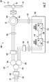
- FIG. 1 illustrates a perspective view of one embodiment of a power generating asset 100 according to the present disclosure.
- the power generating asset 100 may be configured as a wind turbine 114.
- the power generating asset 100 may, for example, be configured as a hydroelectric plant, a fossil fuel generator, and/or a hybrid power generating asset having at least one tower subject to side-to-side oscillations.
- the power generating asset 100 may generally include a tower 102 extending from a support surface 104, a nacelle 106, mounted on the tower 102, and a rotor 108 coupled to the nacelle 106.
- the rotor 108 includes a rotatable hub 110 and at least one rotor blade 112 coupled to and extending outwardly from the hub 110.
- the rotor 108 includes three rotor blades 112.
- the rotor 108 may include more or less than three rotor blades 112.
- Each rotor blade 112 may be spaced about the hub 110 to facilitate rotating the rotor 108 to enable kinetic energy to be transferred from the wind into usable mechanical energy, and subsequently, electrical energy.
- the hub 110 may be rotatably coupled to an electric generator 118 ( FIG. 2 ) (e.g., a double-fed generator) of an electrical system 400 ( FIG. 2 ) positioned within the nacelle 106 to permit electrical energy to be produced.
- the wind turbine 114 may also include a controller 200 centralized within the nacelle 106. However, in other embodiments, the controller 200 may be located within any other component of the wind turbine 114 or at a location outside the wind turbine. Further, the controller 200 may be communicatively coupled to any number of the components of the wind turbine 114 in order to control the components. As such, the controller 200 may include a computer or other suitable processing unit. Thus, in several embodiments, the controller 200 may include suitable computer-readable instructions that, when implemented, configure the controller 200 to perform various different functions, such as receiving, transmitting and/or executing wind turbine control signals.
- the generator 118 may be coupled to the rotor 108 for producing electrical power from the rotational energy generated by the rotor 108.
- the electrical system 400 may include various components for converting the kinetic energy of the rotor 108 into an electrical output in an acceptable form to a connected power grid 179.
- the generator 118 may be a doubly-fed induction generator (DFIG) having a stator 402 and a generator rotor 404.
- the generator 118 may be coupled to a stator bus 406 and a power converter 408 via a rotor bus 410.
- DFIG doubly-fed induction generator
- the stator bus 406 may provide an output multiphase power (e.g. three-phase power) from a stator of the generator 118
- the rotor bus 410 may provide an output multiphase power (e.g. three-phase power) of the generator rotor 404 of the generator 118.
- the generator 118 may be coupled via the rotor bus 410 to a rotor side converter 412.
- the rotor side converter 412 may be coupled to a line-side converter 414 which, in turn, may be coupled to a line-side bus 416.
- the rotor side converter 412 and the line-side converter 414 may be configured for normal operating mode in a three-phase, pulse width modulation (PWM) arrangement using insulated gate bipolar transistors (IGBTs) as switching devices 438.
- IGBTs insulated gate bipolar transistors
- Other suitable switching devices may be used, such as insulated gate commuted thyristors, MOSFETs, bipolar transistors, silicone-controlled rectifiers, and/or other suitable switching devices.
- the rotor side converter 412 and the line-side converter 414 may be coupled via a DC link 418 across a DC link capacitor 420.
- the power converter 408 may be coupled to the controller 200 configured as a converter controller 202 to control the operation of the power converter 408.
- the converter controller 202 may send control commands to the rotor side converter 412 and the line-side converter 414 to control the modulation of switching elements used in the power converter 408 to establish a desired generator torque setpoint and/or power output.
- the electrical system 400 may, in an embodiment, include a transformer 422 coupling the power generating asset of 100 to the power grid 179 via a point of interconnect (POI) 436.
- the transformer 422 may, in an embodiment, be a 3-winding transformer which includes a high voltage (e.g. greater than 12 KVAC) primary winding 424.
- the high voltage primary winding 424 may be coupled to the power grid 179.
- the transformer 422 may also include a medium voltage (e.g. 6 KVAC) secondary winding 426 coupled to the stator bus 406 and a low voltage (e.g. 575 VAC, 690 VAC, etc.) auxiliary winding 428 coupled to the line bus 416.
- the transformer 422 can be a three-winding transformer as depicted, or alternatively, may be a two-winding transformer having only a primary winding 424 and a secondary winding 426; may be a four-winding transformer having a primary winding 424, a secondary winding 426, and auxiliary winding 428, and an additional auxiliary winding; or may have any other suitable number of windings.
- the electrical system 400 may include various protective features (e.g. circuit breakers, fuses, contactors, and other devices) to control and/or protect the various components of the electrical system 400.
- the electrical system 400 may, in an embodiment, include a grid circuit breaker 430, a stator bus circuit breaker 432, and/or a line bus circuit breaker 434.
- the circuit breaker(s) 430, 432, 434 of the electrical system 400 may connect or disconnect corresponding components of the electrical system 400 when a condition of the electrical system 400 approaches a threshold (e.g. a current threshold and/or an operational threshold) of the electrical system 400.
- a threshold e.g. a current threshold and/or an operational threshold
- the power generating asset 100 may include at least one operational sensor 158.
- the operational sensor(s) 158 may be configured to detect a performance of the power generating asset 100, e.g. in response to the environmental condition.
- the operational sensor(s) 158 may be configured to monitor a plurality of electrical conditions, such as slip, stator voltage and current, rotor voltage and current, line-side voltage and current, DC-link charge and/or any other electrical condition of the power generating asset.
- the operational sensor(s) may be a positional sensor and/or an accelerometer configured to detect a side-to-side oscillation of the tower 102.
- the term "monitor” and variations thereof indicates that the various sensors of the power generating asset 100 may be configured to provide a direct measurement of the parameters being monitored or an indirect measurement of such parameters.
- the sensors described herein may, for example, be used to generate signals relating to the parameter being monitored, which can then be utilized by the controller 200 to determine a condition or response of the power generating asset 100.
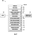
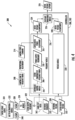
- FIGS.3-5 multiple embodiments of a system 300 for providing grid-forming control of the generator 118 of the power generating asset 100 according to the present disclosure are presented.
- the system 300 may include the controller 200 communicatively coupled to the sensor(s) 158.
- the controller 200 includes one or more processor(s) 206 and associated memory device(s) 208 configured to perform a variety of computer-implemented functions (e.g., performing the methods, steps, calculations and the like and storing relevant data as disclosed herein).
- the controller 200 may also include a communications module 210 to facilitate communications between the controller 200, and the various components of the power generating asset 100.
- the communications module 210 may include a sensor interface 212 (e.g., one or more analog-to-digital converters) to permit signals transmitted from the sensor(s) 158 to be converted into signals that can be understood and processed by the processors 206.
- the sensor(s) 158 may be communicatively coupled to the communications module 210 using any suitable means.
- the sensor(s) 158 may be coupled to the sensor interface 212 via a wired connection.
- the senor(s) 158 may be coupled to the sensor interface 212 via a wireless connection, such as by using any suitable wireless communications protocol known in the art.
- the communications module 210 may also be operably coupled to an operating state control module 214 configured to change at least one turbine operating state of the power generating asset 100, such as an operating state of the generator 118.
- the term "processor” refers not only to integrated circuits referred to in the art as being included in a computer, but also refers to a controller, a microcontroller, a microcomputer, a programmable logic controller (PLC), an application specific integrated circuit, and other programmable circuits.
- the memory device(s) 208 may generally comprise memory element(s) including, but not limited to, computer readable medium (e.g., random access memory (RAM)), computer readable non-volatile medium (e.g., a flash memory), a floppy disk, a compact disc-read only memory (CD-ROM), a magneto-optical disk (MOD), a digital versatile disc (DVD) and/or other suitable memory elements.
- RAM random access memory
- CD-ROM compact disc-read only memory
- MOD magneto-optical disk
- DVD digital versatile disc
- Such memory device(s) 208 may generally be configured to store suitable computer-readable instructions that, when implemented by the processor(s) 206, configure the controller 200 to perform various functions including, but not limited to, determining a power output requirement for the generator 118 based on the stator component of the stator-frequency error and combining the power output requirement with a damping power command corresponding to a desired damping torque to generate a consolidated power requirement for the generator 118 as described herein, as well as various other suitable computer-implemented functions.
- the controller 200 may employ a frequency module 216 to develop the required frequency component of the grid-forming control.
- the frequency module 216 may, in an embodiment, receive a reference frequency 312 and a stator-output frequency 322.
- the reference frequency 312 may correspond to the frequency of the power output of the power generating asset 100 necessary to provide the required grid-forming (e.g., the output frequency of the generator 118 required to support the frequency of the power grid 179).
- a difference between the reference frequency 312 and the stator-output frequency 322 may be utilized to determine a stator-frequency error 302 at a required power output for the stator 402.
- the required power output may be converted to a component of current and compared to a corresponding current component for the stator 402.
- the frequency module 216 may utilize the comparison of the current component to the corresponding current component of the stator 402 to develop a rotor voltage q-component 324, which may be utilized to generate such a rotor voltage setpoint 326 as may be necessary to deliver the required grid-forming control.
- the controller 200 may employ a voltage module 220 to determine a rotor voltage d-component 328 corresponding to a difference between a reference voltage 330 and a stator-output voltage 332.
- the reference voltage 330 may correspond to the voltage of the power output of the power generating asset 100 necessary to provide the required grid-forming (e.g., the output voltage magnitude of the generator 118 required to support the power grid 179).
- the difference between the reference voltage 330 and the stator-output voltage 332 may be utilized to determine a reference reactive power for the stator 402 of the generator 118.
- the reference reactive power may be converted to a component of current and compared to a corresponding current component for the stator 402.
- the voltage module 222 may utilize the comparison of the current components to develop the rotor voltage d-component 328.
- the rotor voltage d-component 328 and the rotor voltage q-component 324 may be combined to generate the rotor voltage setpoint 326 necessary for the delivery of grid-forming control.
- the controller 200 may employ the frequency module 216 to determine a stator-frequency error 302 for the generator 118.
- the frequency module 216 may be employed by the system 300 to determine the frequency components of the stator-frequency error 302. Accordingly, the frequency module 216 may determine at least a stator component 306 of the stator-frequency error 302.
- the frequency module 216 may identify and/or filter out a damping component 308 of the stator-frequency error 302, therefore determining the stator component 306. Based on the stator component 306 of the stator-frequency error 302, the frequency module 216 may determine a power output requirement 310 for the generator 118.
- the frequency module 216 may combine the power output requirement 310 with a damping power command 314, which may be generated in response to the tower damping frequency 344, to develop a consolidated power requirement 316 for the generator 118.
- the controller 200 may, in an embodiment, determine at least one control command 318 for the generator 118 based, at least in part, on the consolidated power requirement 316.
- determining the control command(s) 318 may include determining the rotor voltage setpoint 326 based, at least in part, on the consolidated power requirement 316.
- an operating state 320 of the generator may be changed/altered in order to output a grid-forming voltage and frequency.
- the system 300 may employ the frequency module 216 to determine a difference between the reference frequency for the generator 118 (e.g. the reference frequency for the stator 402 desirable for grid-forming) and the actual stator-output frequency 322.
- the stator-output frequency 322 may be obtained directly from the operational sensor(s) 158 and/or computed from additional parameters of the power generating asset 100 monitored by the operational sensor(s) 158.
- the controller 200 may monitor a three-phase stator output 334 (e.g., three-phase stator output voltage and/or current).
- the three-phase stator output 334 may be expressed in terms of an abc-reference frame.
- the controller 200 may employ an abc-to-dq transfer module 222, to transform the three-phase stator output 334 (e.g., voltage/current) from the abc-reference frame to a dq-reference frame.
- the transformation at step 336 may determine a d-component 338 and a q-component 340 for the stator current/voltage.
- the controller 200 may, in an embodiment, include a phase locked loop module 224. As depicted at 342, the system 300 may, thus, employ the phase locked loop module 224 to determine the stator-output frequency 322. In such an embodiment, the stator-output frequency 322 may be based on the d-component 338 of the three-phase stator output 334.
- stator component 306 of the stator-output frequency 322 may be a DC value.
- the damping component 308 of the frequency error 302 may have one or more sinusoidal frequencies.
- a controller shaping module 218 of the frequency module 216 may, at step 345, establish a gain value of zero at the tower damping frequency 344.
- the controller shaping module 218 may establish a non-zero gain value for values of the stator-frequency error 302 that do not correspond to the tower damping frequency 344.
- the non-zero gain value may have a maximal value when the stator-output frequency 322 has a minimal value and may decrease with an increase in the stator-frequency error 302.
- a high likelihood may exist that the stator-output frequency 322 may be out of phase with the reference frequency 312.
- a large difference between the frequencies 312, 322 may indicate an increased likelihood that at least a portion of the stator-frequency error 302 should be damped or addressed via other control actions.
- the tower damping frequency 344 may be a known value for the power generating asset 100 based on the structural, material, and/or operating characteristics of the power generating asset 100. It should further be appreciated that the establishment of a gain value of zero at the tower damping frequency 344 may preclude the utilization of the tower damping frequencies 344 for the determination of the power output requirement 310 for the stator 402.
- the system 300 may include a band-stop filter 362.
- the band-stop filter 362 may be operably coupled between the phase locked loop module 224 and the frequency module 216.
- the band-stop filter 362 may be configured to block at least a portion of a frequency corresponding to the tower damping frequency 344.
- the band-stop filter 362 may be employed, at 364, to filter the stator-output frequency 322. Filtering the stator-output frequency 322 with the band-stop filter 362 may preclude inclusion of the frequency corresponding to the tower damping frequency 344 in the determined stator-frequency error 302.
- the stator-output frequency 322 delivered to the frequency module 216 may correspond to the stator component 306 of the stator-frequency error 302.
- the controller 200 may determine the tower damping frequency 344 that corresponds to a tower damping torque 366.
- the tower damping torque 366 may correspond to a torque set point of the generator 118 configured to damp tower oscillations (e.g., side-to-side oscillations of the tower 102).
- the controller 200 may then, in an embodiment, combine the tower damping frequency 344 with a grid frequency 368 to determine a modified reference frequency 313.
- the modified reference frequency 313 may be substituted for the reference frequency 312. It should be appreciated that the incorporation of the tower damping frequency 344 into the modified reference frequency 313 may cancel the portion of the stator-output frequency 322 that may be attributable to the tower damping frequency 344. Therefore, the resultant stator-frequency error 302 determined by the frequency module 216 may correspond to the stator component 306.
- the grid frequency 368 may correspond to the frequency of the output of the generator 118 that is required to support the power grid 179.
- determining the damping component 308 and the stator component 306 of the of the stator-frequency error 302 may involve the extraction of a frequency component that matches a tower oscillation frequency while correcting for additional oscillatory components of the stator-frequency error 302.
- the frequency module 216 may be employed to correlate a portion of the stator-frequency error 302 to a known tower oscillation parameter 370 (e.g., a natural frequency of the wind turbine).
- the tower oscillation parameter 370 may result from a plurality of physical attributes of the wind turbine 100 (e.g., tower height, tower diameter, tower wall thickness, tower wall construction, nacelle weight, damping characteristics etc.) and may be known from a turbine design process.
- oscillations within a particular frequency range may correspond to the natural frequency of the tower 102 and may, therefore, indicate tower oscillations to be damped.
- This correlation may, for example, be accomplished via a Fourier transform or other techniques known in the art.
- the frequency module 216 may identify a remainder frequency component 372 of the stator-frequency error 302.
- the remainder frequency component 372 may correspond to a non-tower oscillatory parameter.
- the non-tower oscillatory parameter may correspond to an inter-area oscillation.
- the remainder frequency component 372 may be incorporated into the stator component 306 of the stator-frequency error 302. Accordingly, non-tower oscillatory parameter indicated by the remainder frequency component 302 may be addressed via the power output requirement 310.
- the system 300 may also include the voltage module 220.
- the voltage module 220 may be utilized to determine a stator-voltage error 348 for the generator 118.
- the stator-voltage error 348 may correspond to a difference between the reference voltage 330 and the stator-output voltage 332.
- the stator-output voltage may be the q-component 340 of the three-phase stator output 334.
- the voltage module 220 may determine the required voltage d-component 328 based, at least in part, on the stator-voltage error 348.
- the system 300 may, via the frequency module 216, determine the rotor voltage q-component 324 based, at least in part, on the consolidated power requirement 316.
- rotor voltage q-component 324 determined by the frequency module 216 may be combined with the rotor voltage d-component 328 determined by the voltage module 220.
- the rotor voltage q-component 324 and the rotor voltage d-component 328 may be combined via a dq-to-abc transform module 226 of the controller 200.
- the dq-to-abc transform module 226 may combine and transform the rotor voltage q-component 324 and the rotor voltage d-component 328 to generate the rotor voltage setpoint 326 expressed in the abc-reference frame.
- the system 300 may include a tower-damping module 228.
- the tower-damping module 228 may be configured to generate the damping power command(s) 314 in order to damp the tower oscillation via the modulation of the generator torque torsional It should be appreciated that the damping power command 314 may have a proportional relationship to the damping component 308 of the frequency error 302.
- the damping power command 314 may be directed to achieving the desired level of damping without consideration for the reference frequency 312.
- the development of the consolidated power requirement 316 via the addition of the power output requirement 310 (based on the stator component 306 of the frequency error 302) and the damping power command 314 (determined based on a damping requirement of the tower oscillations) may facilitate the simultaneous addressing of both the grid-forming control requirements and the damping requirements of the power generating asset 100.
Landscapes
- Engineering & Computer Science (AREA)
- Power Engineering (AREA)
- Life Sciences & Earth Sciences (AREA)
- Sustainable Development (AREA)
- Sustainable Energy (AREA)
- Chemical & Material Sciences (AREA)
- Combustion & Propulsion (AREA)
- Mechanical Engineering (AREA)
- General Engineering & Computer Science (AREA)
- Control Of Eletrric Generators (AREA)
Claims (15)
- Verfahren zur Bereitstellung einer netzbildenden Steuerung eines Generators (118), der mit einem Stromnetz (179) verbunden ist, wobei das Verfahren umfasst:Bestimmen eines Statorfrequenzfehlers für den Generator über ein Frequenzmodul (216) einer Steuerung (200);Bestimmen, über das Frequenzmodul, einer Dämpfungskomponente (308) und einer Statorkomponente (306) des Statorfrequenzfehlers, wobei die Dämpfungskomponente mit einer Turmdämpfungsfrequenz (344) korrespondiert;Bestimmen, über das Frequenzmodul, einer Leistungsausgabeanforderung (310) für den Generator, die zumindest teilweise auf der Statorkomponente des Statorfrequenzfehlers basiert;Kombinieren der Leistungsausgabeanforderung über das Frequenzmodul mit einem Dämpfungsleistungsbefehl (314), um eine konsolidierte Leistungsanforderung (316) für den Generator zu entwickeln, wobei der Dämpfungsleistungsbefehl in Reaktion auf die Turm-Dämpfungsfrequenz erzeugt wird; Bestimmen, über die Steuerung, mindestens eines Steuerbefehls (318) für den Generator, zumindest teilweise basierend auf der konsolidierten Leistungsanforderung; undÄndern eines Betriebszustands des Generators (320) in Reaktion auf den mindestens einen Steuerbefehl, um eine netzbildende Spannung und Frequenz auszugeben.
- Verfahren nach Anspruch 1, wobei der Statorfrequenzfehler eine Differenz zwischen einer Referenzfrequenz und einer Statorausgangsfrequenz umfasst.
- Verfahren nach einem der vorhergehenden Ansprüche, wobei das Bestimmen des mindestens einen Steuerbefehls für den Generator ferner umfasst:
Bestimmen eines Rotorspannungssollwerts über die Steuerung, der zumindest teilweise auf der konsolidierten Leistungsanforderung basiert. - Verfahren nach einem der vorhergehenden Ansprüche, ferner umfassend:Überwachen einer dreiphasigen Statorspannung und Stroms des Generators über die Steuerung;Transformieren der dreiphasigen Statorspannung und Statorstroms über ein abc-nachdq-Transfermodul der Steuerung in einen d-q-Bezugsrahmen, um eine d-Komponente und eine q-Komponente für den Strom und die Spannung zu bestimmen; undBestimmen der Statorausgabefrequenz über ein Phasenregelkreis-Modul der Steuerung.
- Verfahren nach einem der vorhergehenden Ansprüche, wobei die Statorkomponente der Statorausgabefrequenz einen Gleichstromwert umfasst, und wobei die Dämpfungskomponente der Statorausgabefrequenz eine Sinusfrequenz umfasst.
- Verfahren nach einem der vorhergehenden Ansprüche, wobei das Bestimmen der Ausgabeanforderung für den Generator ferner umfasst:Ermitteln eines Verstärkungswerts von Null bei der Turm-Dämpfungsfrequenz über ein Steuerungs-Formungsmodul des Frequenzmoduls; undErmitteln eines von Null abweichenden Verstärkungswerts für Werte des Statorfrequenzfehlers, die nicht mit der Turm-Dämpfungsfrequenz korrespondieren, über das Steuerungs-Formungsmodul.
- Verfahren nach einem der vorhergehenden Ansprüche, wobei der von Null abweichende Verstärkungswert einen Maximalwert hat, wenn die Statorausgabefrequenz einen Minimalwert hat, und mit einer Zunahme des Statorfrequenzfehlers abnimmt.
- Verfahren nach einem der vorhergehenden Ansprüche, wobei das Bestimmen des Statorfrequenzfehlers für den Generator ferner umfasst:operatives Koppeln eines Band-Stopp-Filters zwischen dem Phasenregelkreis-Modul und dem Frequenzmodul, wobei der Band-Stopp-Filter so konfiguriert ist, dass er eine Frequenz blockiert, die mit der Turm-Dämpfungsfrequenz korrespondiert; undFiltern der Statorausgabefrequenz über den Band-Stopp-Filter, um die Einbeziehung der Frequenz, die mit der Turm-Dämpfungsfrequenz korrespondiert, in den bestimmten Statorfrequenzfehler auszuschließen.
- Verfahren nach einem der vorhergehenden Ansprüche, wobei das Bestimmen des Statorfrequenzfehlers für den Generator ferner umfasst:Bestimmen der Turm-Dämpfungsfrequenz, über die Steuerung, die mit einem Turm-Dämpfungsdrehmoment korrespondiert, das zum Dämpfen von Turmschwingungen konfiguriert ist;Kombinieren der Turm-Dämpfungsfrequenz mit einer Netzfrequenz, über die Steuerung, um eine modifizierte Referenzfrequenz zu bestimmen; undErsetzen, über die Steuerung, der Referenzfrequenz durch die modifizierte Referenzfrequenz.
- Verfahren nach einem der vorhergehenden Ansprüche, ferner umfassend:Bestimmen eines Statorspannungsfehlers für den Generator über ein Spannungsmodul der Steuerung, wobei der Statorspannungsfehler eine Differenz zwischen einer Referenzspannung und einer Stator-Ausgabespannung umfasst, wobei die Stator-Ausgabespannung die q-Komponente der Statorspannung ist, wobei die Stator-Ausgabespannung eine Spannungsschwingung aufweist, die mit einer Turmschwingung korrespondiert; undBestimmen, über das Spannungsmodul, einer erforderlichen Rotorspannungskomponente d, die zumindest teilweise auf dem Statorspannungsfehler basiert.
- Verfahren nach einem der vorhergehenden Ansprüche, wobei das Bestimmen des mindestens einen Steuerbefehls für den Generator ferner umfasst:Bestimmen, über das Frequenzmodul, einer erforderlichen Rotorspannungskomponente q, die zumindest teilweise auf der konsolidierten Leistungsanforderung basiert; undKombinieren der erforderlichen Rotorspannungskomponente d und der erforderlichen Rotorspannungskomponente q über ein dq-zu-abc-Transformationsmodul der Steuerung, um einen Rotorspannungssollwert zu erzeugen.
- Verfahren nach einem der vorhergehenden Ansprüche, ferner umfassend:Empfangen der Referenzfrequenz über die Steuerung, wobei die Referenzfrequenz mit einer Ausgabefrequenz des Generators korrespondiert, die erforderlich ist, um die Frequenz des Stromnetzes zu unterstützen; undEmpfangen der Referenzspannung über das Steuerung, wobei die Referenzspannung mit einer Ausgabespannungsgröße des Generators korrespondiert, die zur Unterstützung des Stromnetzes erforderlich ist.
- Verfahren nach einem der vorhergehenden Ansprüche, wobei der Dämpfungsleistungsbefehl von einem Turm-Dämpfungsmodul erzeugt wird, das so konfiguriert ist, dass es die Schwingungen des Turms von Seite zu Seite dämpft.
- Verfahren nach einem der vorhergehenden Ansprüche, wobei das Bestimmen der Dämpfungskomponente und der Statorkomponente des Statorfrequenzfehlers ferner umfasst:Korrelieren eines Teils des Statorfrequenzfehlers über das Frequenzmodul mit einem bekannten Turmschwingungsparameter;Identifizieren einer Restfrequenzkomponente des Statorfrequenzfehlers, die mit einem Nicht-Turmschwingungsparameter korrespondiert, über das Frequenzmodul; undEinbeziehen der Restfrequenzkomponente über das Frequenzmodul in die Statorkomponente des Statorfrequenzfehlers.
- System (300) zum Betreiben einer Energieerzeugungsanlage (100), um eine netzbildende Steuerung bereitzustellen, wobei das System umfasst:einen doppelt gespeisten Generator (118), der mit einem Stromnetz (179) verbunden ist; undeine Steuerung (200), die kommunikativ mit dem Generator gekoppelt ist, wobei die Steuerung mindestens einen Prozessor (206) und eine Vielzahl von Modulen umfasst, die so konfiguriert sind, dass sie eine Vielzahl von Operationen durchführen, wobei die Vielzahl von Operationen umfasst:Bestimmen eines Statorfrequenzfehlers für den Generator über ein Frequenzmodul (216) der Steuerung,Bestimmen, über das Frequenzmodul, einer Dämpfungskomponente (308) und einer Statorkomponente (306) des Statorfrequenzfehlers, wobei die Dämpfungskomponente mit einer Turm-Dämpfungsfrequenz (344) korrespondiert,Bestimmen, über das Frequenzmodul, einer Leistungsausgabeanforderung (310) für den Generator, die zumindest teilweise auf der Statorkomponente des Statorfrequenzfehlers basiert,Kombinieren der Leistungsausgabeanforderung über das Frequenzmodul mit einem Dämpfungsleistungsbefehl (314), um eine konsolidierte Leistungsanforderung (316) für den Generator zu entwickeln, wobei der Dämpfungsleistungsbefehl in Reaktion auf die Turm-Dämpfungsfrequenz erzeugt wird,Bestimmen mindestens eines Steuerbefehls (318) für den Generator, der zumindest teilweise auf der konsolidierten Leistungsanforderung basiert, undÄndern eines Betriebszustands des Generators (320) in Reaktion auf den mindestens einen Steuerbefehl, um eine netzbildende Spannung und Frequenz auszugeben.
Applications Claiming Priority (1)
| Application Number | Priority Date | Filing Date | Title |
|---|---|---|---|
| US17/411,164 US11552584B1 (en) | 2021-08-25 | 2021-08-25 | System and methods to address tower damping in a grid forming power generating asset |
Publications (2)
| Publication Number | Publication Date |
|---|---|
| EP4148940A1 EP4148940A1 (de) | 2023-03-15 |
| EP4148940B1 true EP4148940B1 (de) | 2024-05-01 |
Family
ID=82939936
Family Applications (1)
| Application Number | Title | Priority Date | Filing Date |
|---|---|---|---|
| EP22190614.2A Active EP4148940B1 (de) | 2021-08-25 | 2022-08-16 | System und verfahren zum angehen der turmdämpfung in einer netzbildenden stromerzeugungsanlage |
Country Status (5)
| Country | Link |
|---|---|
| US (1) | US11552584B1 (de) |
| EP (1) | EP4148940B1 (de) |
| CN (1) | CN115719970A (de) |
| DK (1) | DK4148940T3 (de) |
| ES (1) | ES2994700T3 (de) |
Cited By (1)
| Publication number | Priority date | Publication date | Assignee | Title |
|---|---|---|---|---|
| WO2025237618A1 (en) * | 2024-05-15 | 2025-11-20 | Siemens Gamesa Renewable Energy A/S | Controlling a power generation system of a wind turbine |
Families Citing this family (2)
| Publication number | Priority date | Publication date | Assignee | Title |
|---|---|---|---|---|
| WO2025252293A1 (en) * | 2024-06-06 | 2025-12-11 | Vestas Wind Systems A/S | Control of power amplitude of stabilizing power provided by a grid forming converter |
| CN120582271A (zh) * | 2025-08-05 | 2025-09-02 | 西安热工研究院有限公司 | 一种超容耦合火电机组智能调控方法、设备、介质和系统 |
Family Cites Families (3)
| Publication number | Priority date | Publication date | Assignee | Title |
|---|---|---|---|---|
| ES2959112T3 (es) | 2013-04-16 | 2024-02-20 | Innomotics Gmbh | Controlador para controlar un convertidor de potencia |
| WO2020200378A1 (en) | 2019-04-04 | 2020-10-08 | Vestas Wind Systems A/S | Control of a wind turbine using split power reference signals |
| EP3779180A1 (de) * | 2019-08-14 | 2021-02-17 | Siemens Gamesa Renewable Energy A/S | Steuerung eines windparks mit windturbinen, die turmschwingungen dämpfen |
-
2021
- 2021-08-25 US US17/411,164 patent/US11552584B1/en active Active
-
2022
- 2022-08-16 ES ES22190614T patent/ES2994700T3/es active Active
- 2022-08-16 EP EP22190614.2A patent/EP4148940B1/de active Active
- 2022-08-16 DK DK22190614.2T patent/DK4148940T3/da active
- 2022-08-25 CN CN202211028759.1A patent/CN115719970A/zh active Pending
Cited By (1)
| Publication number | Priority date | Publication date | Assignee | Title |
|---|---|---|---|---|
| WO2025237618A1 (en) * | 2024-05-15 | 2025-11-20 | Siemens Gamesa Renewable Energy A/S | Controlling a power generation system of a wind turbine |
Also Published As
| Publication number | Publication date |
|---|---|
| ES2994700T3 (en) | 2025-01-30 |
| DK4148940T3 (da) | 2024-08-05 |
| US11552584B1 (en) | 2023-01-10 |
| CN115719970A (zh) | 2023-02-28 |
| EP4148940A1 (de) | 2023-03-15 |
Similar Documents
| Publication | Publication Date | Title |
|---|---|---|
| EP4148940B1 (de) | System und verfahren zum angehen der turmdämpfung in einer netzbildenden stromerzeugungsanlage | |
| EP4027510B1 (de) | System und verfahren zum adressieren von antriebsstrangdämpferschwingungen in einer netzbildenden energieerzeugungsanlage | |
| US8258642B2 (en) | Method and system for resonance dampening in wind turbines | |
| CN114204591A (zh) | 使用虚拟阻抗的基于逆变器的资源的电网形成控制 | |
| AU2009338570A1 (en) | Power system frequency inertia for power generation system | |
| CN114597935A (zh) | 控制基于逆变器的资源的电网形成控制的负序电流的方法 | |
| CN114204592A (zh) | 用于提供基于逆变器的资源的电网形成控制的系统和方法 | |
| EP4187739B1 (de) | System und verfahren zur dämpfung von subsynchronen steuerungsinteraktionen in einer netzbildenden wechselrichterbasierten ressource | |
| CN114597936A (zh) | 为双馈风力涡轮发电机提供电网形成控制的系统和方法 | |
| EP4170851A1 (de) | System und verfahren zur steuerung eines stromerzeugungsvermögens mit einer nicht lieferbaren komponente einer gesamtleistungsausgabe | |
| CN111316521B (zh) | 用于控制连接到电力网的电功率系统的系统和方法 | |
| CN114977268A (zh) | 为双馈风力涡轮发电机提供电网形成控制的系统和方法 | |
| EP4175105B1 (de) | System und verfahren zur verringerung der instabilität bei einem blindleistungsbefehl einer wechselrichterbasierten ressource | |
| US20250070697A1 (en) | System and method for decoupling current command components in a synchronously-rotating frame | |
| WO2024167493A1 (en) | Grid-forming island detection and continuous operation of an inverter-based resource | |
| CN120153546A (zh) | 用于在电网形成型基于逆变器的资源中提供速度相关的电网频率支持的系统及方法 | |
| US12451696B2 (en) | System and method of decoupling drivetrain related power oscillations of an inverter-based resource from active power injected into the electrical grid | |
| US12404835B1 (en) | System and method for reducing drivetrain coupling torques after a grid event | |
| US11967824B2 (en) | Adaptive gain control for a reactive power regulator of an inverter-based resource |
Legal Events
| Date | Code | Title | Description |
|---|---|---|---|
| PUAI | Public reference made under article 153(3) epc to a published international application that has entered the european phase |
Free format text: ORIGINAL CODE: 0009012 |
|
| STAA | Information on the status of an ep patent application or granted ep patent |
Free format text: STATUS: THE APPLICATION HAS BEEN PUBLISHED |
|
| AK | Designated contracting states |
Kind code of ref document: A1 Designated state(s): AL AT BE BG CH CY CZ DE DK EE ES FI FR GB GR HR HU IE IS IT LI LT LU LV MC MK MT NL NO PL PT RO RS SE SI SK SM TR |
|
| P01 | Opt-out of the competence of the unified patent court (upc) registered |
Effective date: 20230530 |
|
| STAA | Information on the status of an ep patent application or granted ep patent |
Free format text: STATUS: REQUEST FOR EXAMINATION WAS MADE |
|
| 17P | Request for examination filed |
Effective date: 20230724 |
|
| RBV | Designated contracting states (corrected) |
Designated state(s): AL AT BE BG CH CY CZ DE DK EE ES FI FR GB GR HR HU IE IS IT LI LT LU LV MC MK MT NL NO PL PT RO RS SE SI SK SM TR |
|
| GRAP | Despatch of communication of intention to grant a patent |
Free format text: ORIGINAL CODE: EPIDOSNIGR1 |
|
| STAA | Information on the status of an ep patent application or granted ep patent |
Free format text: STATUS: GRANT OF PATENT IS INTENDED |
|
| RIC1 | Information provided on ipc code assigned before grant |
Ipc: H02P 29/50 20160101ALI20231128BHEP Ipc: H02P 9/48 20060101ALI20231128BHEP Ipc: H02P 9/00 20060101ALI20231128BHEP Ipc: F03D 7/02 20060101ALI20231128BHEP Ipc: H02J 3/38 20060101ALI20231128BHEP Ipc: H02J 3/24 20060101AFI20231128BHEP |
|
| INTG | Intention to grant announced |
Effective date: 20240103 |
|
| GRAS | Grant fee paid |
Free format text: ORIGINAL CODE: EPIDOSNIGR3 |
|
| GRAA | (expected) grant |
Free format text: ORIGINAL CODE: 0009210 |
|
| STAA | Information on the status of an ep patent application or granted ep patent |
Free format text: STATUS: THE PATENT HAS BEEN GRANTED |
|
| AK | Designated contracting states |
Kind code of ref document: B1 Designated state(s): AL AT BE BG CH CY CZ DE DK EE ES FI FR GB GR HR HU IE IS IT LI LT LU LV MC MK MT NL NO PL PT RO RS SE SI SK SM TR |
|
| REG | Reference to a national code |
Ref country code: GB Ref legal event code: FG4D |
|
| REG | Reference to a national code |
Ref country code: CH Ref legal event code: EP |
|
| REG | Reference to a national code |
Ref country code: IE Ref legal event code: FG4D |
|
| REG | Reference to a national code |
Ref country code: DE Ref legal event code: R096 Ref document number: 602022003197 Country of ref document: DE |
|
| REG | Reference to a national code |
Ref country code: DK Ref legal event code: T3 Effective date: 20240730 |
|
| REG | Reference to a national code |
Ref country code: LT Ref legal event code: MG9D |
|
| REG | Reference to a national code |
Ref country code: NL Ref legal event code: MP Effective date: 20240501 |
|
| PG25 | Lapsed in a contracting state [announced via postgrant information from national office to epo] |
Ref country code: IS Free format text: LAPSE BECAUSE OF FAILURE TO SUBMIT A TRANSLATION OF THE DESCRIPTION OR TO PAY THE FEE WITHIN THE PRESCRIBED TIME-LIMIT Effective date: 20240901 |
|
| PG25 | Lapsed in a contracting state [announced via postgrant information from national office to epo] |
Ref country code: BG Free format text: LAPSE BECAUSE OF FAILURE TO SUBMIT A TRANSLATION OF THE DESCRIPTION OR TO PAY THE FEE WITHIN THE PRESCRIBED TIME-LIMIT Effective date: 20240501 |
|
| PG25 | Lapsed in a contracting state [announced via postgrant information from national office to epo] |
Ref country code: HR Free format text: LAPSE BECAUSE OF FAILURE TO SUBMIT A TRANSLATION OF THE DESCRIPTION OR TO PAY THE FEE WITHIN THE PRESCRIBED TIME-LIMIT Effective date: 20240501 Ref country code: FI Free format text: LAPSE BECAUSE OF FAILURE TO SUBMIT A TRANSLATION OF THE DESCRIPTION OR TO PAY THE FEE WITHIN THE PRESCRIBED TIME-LIMIT Effective date: 20240501 |
|
| PG25 | Lapsed in a contracting state [announced via postgrant information from national office to epo] |
Ref country code: GR Free format text: LAPSE BECAUSE OF FAILURE TO SUBMIT A TRANSLATION OF THE DESCRIPTION OR TO PAY THE FEE WITHIN THE PRESCRIBED TIME-LIMIT Effective date: 20240802 |
|
| PG25 | Lapsed in a contracting state [announced via postgrant information from national office to epo] |
Ref country code: PT Free format text: LAPSE BECAUSE OF FAILURE TO SUBMIT A TRANSLATION OF THE DESCRIPTION OR TO PAY THE FEE WITHIN THE PRESCRIBED TIME-LIMIT Effective date: 20240902 |
|
| REG | Reference to a national code |
Ref country code: AT Ref legal event code: MK05 Ref document number: 1683739 Country of ref document: AT Kind code of ref document: T Effective date: 20240501 |
|
| PG25 | Lapsed in a contracting state [announced via postgrant information from national office to epo] |
Ref country code: NL Free format text: LAPSE BECAUSE OF FAILURE TO SUBMIT A TRANSLATION OF THE DESCRIPTION OR TO PAY THE FEE WITHIN THE PRESCRIBED TIME-LIMIT Effective date: 20240501 |
|
| PG25 | Lapsed in a contracting state [announced via postgrant information from national office to epo] |
Ref country code: AT Free format text: LAPSE BECAUSE OF FAILURE TO SUBMIT A TRANSLATION OF THE DESCRIPTION OR TO PAY THE FEE WITHIN THE PRESCRIBED TIME-LIMIT Effective date: 20240501 |
|
| PG25 | Lapsed in a contracting state [announced via postgrant information from national office to epo] |
Ref country code: PL Free format text: LAPSE BECAUSE OF FAILURE TO SUBMIT A TRANSLATION OF THE DESCRIPTION OR TO PAY THE FEE WITHIN THE PRESCRIBED TIME-LIMIT Effective date: 20240501 |
|
| PG25 | Lapsed in a contracting state [announced via postgrant information from national office to epo] |
Ref country code: LV Free format text: LAPSE BECAUSE OF FAILURE TO SUBMIT A TRANSLATION OF THE DESCRIPTION OR TO PAY THE FEE WITHIN THE PRESCRIBED TIME-LIMIT Effective date: 20240501 |
|
| PG25 | Lapsed in a contracting state [announced via postgrant information from national office to epo] |
Ref country code: PT Free format text: LAPSE BECAUSE OF FAILURE TO SUBMIT A TRANSLATION OF THE DESCRIPTION OR TO PAY THE FEE WITHIN THE PRESCRIBED TIME-LIMIT Effective date: 20240902 Ref country code: PL Free format text: LAPSE BECAUSE OF FAILURE TO SUBMIT A TRANSLATION OF THE DESCRIPTION OR TO PAY THE FEE WITHIN THE PRESCRIBED TIME-LIMIT Effective date: 20240501 Ref country code: NO Free format text: LAPSE BECAUSE OF FAILURE TO SUBMIT A TRANSLATION OF THE DESCRIPTION OR TO PAY THE FEE WITHIN THE PRESCRIBED TIME-LIMIT Effective date: 20240801 Ref country code: NL Free format text: LAPSE BECAUSE OF FAILURE TO SUBMIT A TRANSLATION OF THE DESCRIPTION OR TO PAY THE FEE WITHIN THE PRESCRIBED TIME-LIMIT Effective date: 20240501 Ref country code: LV Free format text: LAPSE BECAUSE OF FAILURE TO SUBMIT A TRANSLATION OF THE DESCRIPTION OR TO PAY THE FEE WITHIN THE PRESCRIBED TIME-LIMIT Effective date: 20240501 Ref country code: IS Free format text: LAPSE BECAUSE OF FAILURE TO SUBMIT A TRANSLATION OF THE DESCRIPTION OR TO PAY THE FEE WITHIN THE PRESCRIBED TIME-LIMIT Effective date: 20240901 Ref country code: HR Free format text: LAPSE BECAUSE OF FAILURE TO SUBMIT A TRANSLATION OF THE DESCRIPTION OR TO PAY THE FEE WITHIN THE PRESCRIBED TIME-LIMIT Effective date: 20240501 Ref country code: GR Free format text: LAPSE BECAUSE OF FAILURE TO SUBMIT A TRANSLATION OF THE DESCRIPTION OR TO PAY THE FEE WITHIN THE PRESCRIBED TIME-LIMIT Effective date: 20240802 Ref country code: FI Free format text: LAPSE BECAUSE OF FAILURE TO SUBMIT A TRANSLATION OF THE DESCRIPTION OR TO PAY THE FEE WITHIN THE PRESCRIBED TIME-LIMIT Effective date: 20240501 Ref country code: BG Free format text: LAPSE BECAUSE OF FAILURE TO SUBMIT A TRANSLATION OF THE DESCRIPTION OR TO PAY THE FEE WITHIN THE PRESCRIBED TIME-LIMIT Effective date: 20240501 Ref country code: AT Free format text: LAPSE BECAUSE OF FAILURE TO SUBMIT A TRANSLATION OF THE DESCRIPTION OR TO PAY THE FEE WITHIN THE PRESCRIBED TIME-LIMIT Effective date: 20240501 Ref country code: RS Free format text: LAPSE BECAUSE OF FAILURE TO SUBMIT A TRANSLATION OF THE DESCRIPTION OR TO PAY THE FEE WITHIN THE PRESCRIBED TIME-LIMIT Effective date: 20240801 |
|
| PG25 | Lapsed in a contracting state [announced via postgrant information from national office to epo] |
Ref country code: EE Free format text: LAPSE BECAUSE OF FAILURE TO SUBMIT A TRANSLATION OF THE DESCRIPTION OR TO PAY THE FEE WITHIN THE PRESCRIBED TIME-LIMIT Effective date: 20240501 |
|
| PG25 | Lapsed in a contracting state [announced via postgrant information from national office to epo] |
Ref country code: CZ Free format text: LAPSE BECAUSE OF FAILURE TO SUBMIT A TRANSLATION OF THE DESCRIPTION OR TO PAY THE FEE WITHIN THE PRESCRIBED TIME-LIMIT Effective date: 20240501 |
|
| PG25 | Lapsed in a contracting state [announced via postgrant information from national office to epo] |
Ref country code: RO Free format text: LAPSE BECAUSE OF FAILURE TO SUBMIT A TRANSLATION OF THE DESCRIPTION OR TO PAY THE FEE WITHIN THE PRESCRIBED TIME-LIMIT Effective date: 20240501 Ref country code: SK Free format text: LAPSE BECAUSE OF FAILURE TO SUBMIT A TRANSLATION OF THE DESCRIPTION OR TO PAY THE FEE WITHIN THE PRESCRIBED TIME-LIMIT Effective date: 20240501 |
|
| PG25 | Lapsed in a contracting state [announced via postgrant information from national office to epo] |
Ref country code: SM Free format text: LAPSE BECAUSE OF FAILURE TO SUBMIT A TRANSLATION OF THE DESCRIPTION OR TO PAY THE FEE WITHIN THE PRESCRIBED TIME-LIMIT Effective date: 20240501 |
|
| REG | Reference to a national code |
Ref country code: ES Ref legal event code: FG2A Ref document number: 2994700 Country of ref document: ES Kind code of ref document: T3 Effective date: 20250130 |
|
| PG25 | Lapsed in a contracting state [announced via postgrant information from national office to epo] |
Ref country code: SM Free format text: LAPSE BECAUSE OF FAILURE TO SUBMIT A TRANSLATION OF THE DESCRIPTION OR TO PAY THE FEE WITHIN THE PRESCRIBED TIME-LIMIT Effective date: 20240501 Ref country code: SK Free format text: LAPSE BECAUSE OF FAILURE TO SUBMIT A TRANSLATION OF THE DESCRIPTION OR TO PAY THE FEE WITHIN THE PRESCRIBED TIME-LIMIT Effective date: 20240501 Ref country code: RO Free format text: LAPSE BECAUSE OF FAILURE TO SUBMIT A TRANSLATION OF THE DESCRIPTION OR TO PAY THE FEE WITHIN THE PRESCRIBED TIME-LIMIT Effective date: 20240501 Ref country code: EE Free format text: LAPSE BECAUSE OF FAILURE TO SUBMIT A TRANSLATION OF THE DESCRIPTION OR TO PAY THE FEE WITHIN THE PRESCRIBED TIME-LIMIT Effective date: 20240501 Ref country code: CZ Free format text: LAPSE BECAUSE OF FAILURE TO SUBMIT A TRANSLATION OF THE DESCRIPTION OR TO PAY THE FEE WITHIN THE PRESCRIBED TIME-LIMIT Effective date: 20240501 |
|
| REG | Reference to a national code |
Ref country code: DE Ref legal event code: R097 Ref document number: 602022003197 Country of ref document: DE |
|
| PG25 | Lapsed in a contracting state [announced via postgrant information from national office to epo] |
Ref country code: IT Free format text: LAPSE BECAUSE OF FAILURE TO SUBMIT A TRANSLATION OF THE DESCRIPTION OR TO PAY THE FEE WITHIN THE PRESCRIBED TIME-LIMIT Effective date: 20240501 |
|
| PLBE | No opposition filed within time limit |
Free format text: ORIGINAL CODE: 0009261 |
|
| STAA | Information on the status of an ep patent application or granted ep patent |
Free format text: STATUS: NO OPPOSITION FILED WITHIN TIME LIMIT |
|
| 26N | No opposition filed |
Effective date: 20250204 |
|
| PG25 | Lapsed in a contracting state [announced via postgrant information from national office to epo] |
Ref country code: LU Free format text: LAPSE BECAUSE OF NON-PAYMENT OF DUE FEES Effective date: 20240816 |
|
| PG25 | Lapsed in a contracting state [announced via postgrant information from national office to epo] |
Ref country code: SI Free format text: LAPSE BECAUSE OF FAILURE TO SUBMIT A TRANSLATION OF THE DESCRIPTION OR TO PAY THE FEE WITHIN THE PRESCRIBED TIME-LIMIT Effective date: 20240501 Ref country code: MC Free format text: LAPSE BECAUSE OF FAILURE TO SUBMIT A TRANSLATION OF THE DESCRIPTION OR TO PAY THE FEE WITHIN THE PRESCRIBED TIME-LIMIT Effective date: 20240501 |
|
| REG | Reference to a national code |
Ref country code: BE Ref legal event code: MM Effective date: 20240831 |
|
| PG25 | Lapsed in a contracting state [announced via postgrant information from national office to epo] |
Ref country code: BE Free format text: LAPSE BECAUSE OF NON-PAYMENT OF DUE FEES Effective date: 20240831 |
|
| PG25 | Lapsed in a contracting state [announced via postgrant information from national office to epo] |
Ref country code: FR Free format text: LAPSE BECAUSE OF NON-PAYMENT OF DUE FEES Effective date: 20240831 |
|
| PG25 | Lapsed in a contracting state [announced via postgrant information from national office to epo] |
Ref country code: IE Free format text: LAPSE BECAUSE OF NON-PAYMENT OF DUE FEES Effective date: 20240816 |
|
| PG25 | Lapsed in a contracting state [announced via postgrant information from national office to epo] |
Ref country code: SE Free format text: LAPSE BECAUSE OF FAILURE TO SUBMIT A TRANSLATION OF THE DESCRIPTION OR TO PAY THE FEE WITHIN THE PRESCRIBED TIME-LIMIT Effective date: 20240501 |
|
| PGFP | Annual fee paid to national office [announced via postgrant information from national office to epo] |
Ref country code: ES Payment date: 20250901 Year of fee payment: 4 |
|
| PGFP | Annual fee paid to national office [announced via postgrant information from national office to epo] |
Ref country code: DK Payment date: 20250723 Year of fee payment: 4 Ref country code: DE Payment date: 20250724 Year of fee payment: 4 |
|
| REG | Reference to a national code |
Ref country code: DE Ref legal event code: R079 Ref document number: 602022003197 Country of ref document: DE Free format text: PREVIOUS MAIN CLASS: H02J0003240000 Ipc: H02J0003001400 |
|
| PG25 | Lapsed in a contracting state [announced via postgrant information from national office to epo] |
Ref country code: CY Free format text: LAPSE BECAUSE OF FAILURE TO SUBMIT A TRANSLATION OF THE DESCRIPTION OR TO PAY THE FEE WITHIN THE PRESCRIBED TIME-LIMIT; INVALID AB INITIO Effective date: 20220816 |
|
| PG25 | Lapsed in a contracting state [announced via postgrant information from national office to epo] |
Ref country code: HU Free format text: LAPSE BECAUSE OF FAILURE TO SUBMIT A TRANSLATION OF THE DESCRIPTION OR TO PAY THE FEE WITHIN THE PRESCRIBED TIME-LIMIT; INVALID AB INITIO Effective date: 20220816 |
|
| REG | Reference to a national code |
Ref country code: CH Ref legal event code: H13 Free format text: ST27 STATUS EVENT CODE: U-0-0-H10-H13 (AS PROVIDED BY THE NATIONAL OFFICE) Effective date: 20260324 |