EP4421437A1 - Wärmeübertragerplatte und verfahren zur herstellung einer wärmeübertragerplatte - Google Patents
Wärmeübertragerplatte und verfahren zur herstellung einer wärmeübertragerplatte Download PDFInfo
- Publication number
- EP4421437A1 EP4421437A1 EP23158875.7A EP23158875A EP4421437A1 EP 4421437 A1 EP4421437 A1 EP 4421437A1 EP 23158875 A EP23158875 A EP 23158875A EP 4421437 A1 EP4421437 A1 EP 4421437A1
- Authority
- EP
- European Patent Office
- Prior art keywords
- section
- plate
- connection
- heat exchanger
- tool
- Prior art date
- Legal status (The legal status is an assumption and is not a legal conclusion. Google has not performed a legal analysis and makes no representation as to the accuracy of the status listed.)
- Granted
Links
Images




Classifications
-
- F—MECHANICAL ENGINEERING; LIGHTING; HEATING; WEAPONS; BLASTING
- F28—HEAT EXCHANGE IN GENERAL
- F28D—HEAT-EXCHANGE APPARATUS, NOT PROVIDED FOR IN ANOTHER SUBCLASS, IN WHICH THE HEAT-EXCHANGE MEDIA DO NOT COME INTO DIRECT CONTACT
- F28D1/00—Heat-exchange apparatus having stationary conduit assemblies for one heat-exchange medium only, the media being in contact with different sides of the conduit wall, in which the other heat-exchange medium is a large body of fluid, e.g. domestic or motor car radiators
- F28D1/02—Heat-exchange apparatus having stationary conduit assemblies for one heat-exchange medium only, the media being in contact with different sides of the conduit wall, in which the other heat-exchange medium is a large body of fluid, e.g. domestic or motor car radiators with heat-exchange conduits immersed in the body of fluid
- F28D1/03—Heat-exchange apparatus having stationary conduit assemblies for one heat-exchange medium only, the media being in contact with different sides of the conduit wall, in which the other heat-exchange medium is a large body of fluid, e.g. domestic or motor car radiators with heat-exchange conduits immersed in the body of fluid with plate-like or laminated conduits
- F28D1/0308—Heat-exchange apparatus having stationary conduit assemblies for one heat-exchange medium only, the media being in contact with different sides of the conduit wall, in which the other heat-exchange medium is a large body of fluid, e.g. domestic or motor car radiators with heat-exchange conduits immersed in the body of fluid with plate-like or laminated conduits the conduits being formed by paired plates touching each other
-
- F—MECHANICAL ENGINEERING; LIGHTING; HEATING; WEAPONS; BLASTING
- F28—HEAT EXCHANGE IN GENERAL
- F28F—DETAILS OF HEAT-EXCHANGE AND HEAT-TRANSFER APPARATUS, OF GENERAL APPLICATION
- F28F3/00—Plate-like or laminated elements; Assemblies of plate-like or laminated elements
- F28F3/12—Elements constructed in the shape of a hollow panel, e.g. with channels
-
- B—PERFORMING OPERATIONS; TRANSPORTING
- B21—MECHANICAL METAL-WORKING WITHOUT ESSENTIALLY REMOVING MATERIAL; PUNCHING METAL
- B21D—WORKING OR PROCESSING OF SHEET METAL OR METAL TUBES, RODS OR PROFILES WITHOUT ESSENTIALLY REMOVING MATERIAL; PUNCHING METAL
- B21D53/00—Making other particular articles
- B21D53/02—Making other particular articles heat exchangers or parts thereof, e.g. radiators, condensers fins, headers
- B21D53/04—Making other particular articles heat exchangers or parts thereof, e.g. radiators, condensers fins, headers of sheet metal
- B21D53/045—Making other particular articles heat exchangers or parts thereof, e.g. radiators, condensers fins, headers of sheet metal by inflating partially united plates
-
- B—PERFORMING OPERATIONS; TRANSPORTING
- B23—MACHINE TOOLS; METAL-WORKING NOT OTHERWISE PROVIDED FOR
- B23K—SOLDERING OR UNSOLDERING; WELDING; CLADDING OR PLATING BY SOLDERING OR WELDING; CUTTING BY APPLYING HEAT LOCALLY, e.g. FLAME CUTTING; WORKING BY LASER BEAM
- B23K1/00—Soldering, e.g. brazing, or unsoldering
- B23K1/0008—Soldering, e.g. brazing, or unsoldering specially adapted for particular articles or work
- B23K1/0012—Brazing of heat exchangers
-
- B—PERFORMING OPERATIONS; TRANSPORTING
- B23—MACHINE TOOLS; METAL-WORKING NOT OTHERWISE PROVIDED FOR
- B23K—SOLDERING OR UNSOLDERING; WELDING; CLADDING OR PLATING BY SOLDERING OR WELDING; CUTTING BY APPLYING HEAT LOCALLY, e.g. FLAME CUTTING; WORKING BY LASER BEAM
- B23K1/00—Soldering, e.g. brazing, or unsoldering
- B23K1/20—Preliminary treatment of work or areas to be soldered, e.g. in respect of a galvanic coating
-
- F—MECHANICAL ENGINEERING; LIGHTING; HEATING; WEAPONS; BLASTING
- F28—HEAT EXCHANGE IN GENERAL
- F28F—DETAILS OF HEAT-EXCHANGE AND HEAT-TRANSFER APPARATUS, OF GENERAL APPLICATION
- F28F9/00—Casings; Header boxes; Auxiliary supports for elements; Auxiliary members within casings
- F28F9/02—Header boxes; End plates
- F28F9/0246—Arrangements for connecting header boxes with flow lines
- F28F9/0248—Arrangements for sealing connectors to header boxes
-
- F—MECHANICAL ENGINEERING; LIGHTING; HEATING; WEAPONS; BLASTING
- F28—HEAT EXCHANGE IN GENERAL
- F28F—DETAILS OF HEAT-EXCHANGE AND HEAT-TRANSFER APPARATUS, OF GENERAL APPLICATION
- F28F9/00—Casings; Header boxes; Auxiliary supports for elements; Auxiliary members within casings
- F28F9/02—Header boxes; End plates
- F28F9/0246—Arrangements for connecting header boxes with flow lines
- F28F9/0256—Arrangements for coupling connectors with flow lines
-
- H—ELECTRICITY
- H01—ELECTRIC ELEMENTS
- H01M—PROCESSES OR MEANS, e.g. BATTERIES, FOR THE DIRECT CONVERSION OF CHEMICAL ENERGY INTO ELECTRICAL ENERGY
- H01M10/00—Secondary cells; Manufacture thereof
- H01M10/60—Heating or cooling; Temperature control
- H01M10/61—Types of temperature control
- H01M10/613—Cooling or keeping cold
-
- H—ELECTRICITY
- H01—ELECTRIC ELEMENTS
- H01M—PROCESSES OR MEANS, e.g. BATTERIES, FOR THE DIRECT CONVERSION OF CHEMICAL ENERGY INTO ELECTRICAL ENERGY
- H01M10/00—Secondary cells; Manufacture thereof
- H01M10/60—Heating or cooling; Temperature control
- H01M10/62—Heating or cooling; Temperature control specially adapted for specific applications
- H01M10/625—Vehicles
-
- H—ELECTRICITY
- H01—ELECTRIC ELEMENTS
- H01M—PROCESSES OR MEANS, e.g. BATTERIES, FOR THE DIRECT CONVERSION OF CHEMICAL ENERGY INTO ELECTRICAL ENERGY
- H01M10/00—Secondary cells; Manufacture thereof
- H01M10/60—Heating or cooling; Temperature control
- H01M10/65—Means for temperature control structurally associated with the cells
- H01M10/655—Solid structures for heat exchange or heat conduction
-
- H—ELECTRICITY
- H01—ELECTRIC ELEMENTS
- H01M—PROCESSES OR MEANS, e.g. BATTERIES, FOR THE DIRECT CONVERSION OF CHEMICAL ENERGY INTO ELECTRICAL ENERGY
- H01M10/00—Secondary cells; Manufacture thereof
- H01M10/60—Heating or cooling; Temperature control
- H01M10/65—Means for temperature control structurally associated with the cells
- H01M10/655—Solid structures for heat exchange or heat conduction
- H01M10/6554—Rods or plates
-
- H—ELECTRICITY
- H01—ELECTRIC ELEMENTS
- H01M—PROCESSES OR MEANS, e.g. BATTERIES, FOR THE DIRECT CONVERSION OF CHEMICAL ENERGY INTO ELECTRICAL ENERGY
- H01M10/00—Secondary cells; Manufacture thereof
- H01M10/60—Heating or cooling; Temperature control
- H01M10/65—Means for temperature control structurally associated with the cells
- H01M10/655—Solid structures for heat exchange or heat conduction
- H01M10/6556—Solid parts with flow channel passages or pipes for heat exchange
-
- H—ELECTRICITY
- H01—ELECTRIC ELEMENTS
- H01M—PROCESSES OR MEANS, e.g. BATTERIES, FOR THE DIRECT CONVERSION OF CHEMICAL ENERGY INTO ELECTRICAL ENERGY
- H01M10/00—Secondary cells; Manufacture thereof
- H01M10/60—Heating or cooling; Temperature control
- H01M10/65—Means for temperature control structurally associated with the cells
- H01M10/656—Means for temperature control structurally associated with the cells characterised by the type of heat-exchange fluid
- H01M10/6567—Liquids
-
- B—PERFORMING OPERATIONS; TRANSPORTING
- B23—MACHINE TOOLS; METAL-WORKING NOT OTHERWISE PROVIDED FOR
- B23K—SOLDERING OR UNSOLDERING; WELDING; CLADDING OR PLATING BY SOLDERING OR WELDING; CUTTING BY APPLYING HEAT LOCALLY, e.g. FLAME CUTTING; WORKING BY LASER BEAM
- B23K2101/00—Articles made by soldering, welding or cutting
- B23K2101/04—Tubular or hollow articles
- B23K2101/14—Heat exchangers
-
- F—MECHANICAL ENGINEERING; LIGHTING; HEATING; WEAPONS; BLASTING
- F28—HEAT EXCHANGE IN GENERAL
- F28D—HEAT-EXCHANGE APPARATUS, NOT PROVIDED FOR IN ANOTHER SUBCLASS, IN WHICH THE HEAT-EXCHANGE MEDIA DO NOT COME INTO DIRECT CONTACT
- F28D21/00—Heat-exchange apparatus not covered by any of the groups F28D1/00 - F28D20/00
- F28D2021/0019—Other heat exchangers for particular applications; Heat exchange systems not otherwise provided for
- F28D2021/0028—Other heat exchangers for particular applications; Heat exchange systems not otherwise provided for for cooling heat generating elements, e.g. for cooling electronic components or electric devices
- F28D2021/0029—Heat sinks
-
- F—MECHANICAL ENGINEERING; LIGHTING; HEATING; WEAPONS; BLASTING
- F28—HEAT EXCHANGE IN GENERAL
- F28D—HEAT-EXCHANGE APPARATUS, NOT PROVIDED FOR IN ANOTHER SUBCLASS, IN WHICH THE HEAT-EXCHANGE MEDIA DO NOT COME INTO DIRECT CONTACT
- F28D21/00—Heat-exchange apparatus not covered by any of the groups F28D1/00 - F28D20/00
- F28D2021/0019—Other heat exchangers for particular applications; Heat exchange systems not otherwise provided for
- F28D2021/0043—Other heat exchangers for particular applications; Heat exchange systems not otherwise provided for for fuel cells
-
- F—MECHANICAL ENGINEERING; LIGHTING; HEATING; WEAPONS; BLASTING
- F28—HEAT EXCHANGE IN GENERAL
- F28F—DETAILS OF HEAT-EXCHANGE AND HEAT-TRANSFER APPARATUS, OF GENERAL APPLICATION
- F28F2255/00—Heat exchanger elements made of materials having special features or resulting from particular manufacturing processes
- F28F2255/14—Heat exchanger elements made of materials having special features or resulting from particular manufacturing processes molded
-
- F—MECHANICAL ENGINEERING; LIGHTING; HEATING; WEAPONS; BLASTING
- F28—HEAT EXCHANGE IN GENERAL
- F28F—DETAILS OF HEAT-EXCHANGE AND HEAT-TRANSFER APPARATUS, OF GENERAL APPLICATION
- F28F2275/00—Fastening; Joining
- F28F2275/04—Fastening; Joining by brazing
-
- Y—GENERAL TAGGING OF NEW TECHNOLOGICAL DEVELOPMENTS; GENERAL TAGGING OF CROSS-SECTIONAL TECHNOLOGIES SPANNING OVER SEVERAL SECTIONS OF THE IPC; TECHNICAL SUBJECTS COVERED BY FORMER USPC CROSS-REFERENCE ART COLLECTIONS [XRACs] AND DIGESTS
- Y02—TECHNOLOGIES OR APPLICATIONS FOR MITIGATION OR ADAPTATION AGAINST CLIMATE CHANGE
- Y02E—REDUCTION OF GREENHOUSE GAS [GHG] EMISSIONS, RELATED TO ENERGY GENERATION, TRANSMISSION OR DISTRIBUTION
- Y02E60/00—Enabling technologies; Technologies with a potential or indirect contribution to GHG emissions mitigation
- Y02E60/10—Energy storage using batteries
Definitions
- the invention relates to a heat exchanger plate and a method for producing heat exchanger plates.
- Heat exchanger plates are used for a wide variety of applications.
- a heat exchanger plate of the type in question here is, in particular, a cooling plate for cooling batteries in motor vehicles.
- tempering elements are heat exchanger plates in the form of cooling plates that are arranged above, to the side and/or below a battery module.
- Conventional heat exchanger plates usually consist of joined aluminum sheets or extruded aluminum profiles, which allow the temperature control medium or cooling fluid to flow through the heat exchanger plates via connecting pieces.
- the connecting pieces are usually manufactured by shaping or machining and connected to the plate body of a cooling plate.
- the connecting pieces are designed in such a way that they enable the cooling fluid lines to be installed quickly.
- a cooling plate with a plate body formed from two plate elements is part of the state of the art, in which fluid connections or connection pieces for cooling fluid are arranged on a flat surface of a plate element parallel to the surface of the plate element.
- the plate body is formed from two plate elements and has connection pieces for cooling fluid, wherein a connection piece is aligned parallel to the plane of the plate elements and is joined to a connection section in a receiving section of the plate body.
- the EN 10 2010 051 106 B4 discloses a cooling plate which has at least one cooling channel for conducting a coolant, which is provided with at least one inlet and at least one outlet.
- the cooling plate has at least two plate elements which lie flat against one another and in which bulges are formed which together form a cooling channel.
- the inlet and the outlet are each provided with a connection piece for connecting the cooling channel to a coolant connection unit.
- the invention is based on the object of creating a functionally and technically improved heat exchanger plate and of demonstrating a method for producing a heat exchanger plate, which ensures an assembly-friendly, process-reliable and cost-effective joining of a connection piece to the plate body of a heat exchanger plate.
- a heat exchanger plate has a plate body formed from two plate elements and connecting pieces for the supply and discharge of a cooling fluid.
- the plate elements are in particular a channel plate and a base plate, which are brought together to form a plate stack and joined together to form the plate body.
- the connecting pieces are joined to the plate body.
- At least one connecting piece has a connecting section which is joined in a receiving section of the plate body formed between the plate elements. The alignment of the connecting section of the connecting piece is parallel to the plane of the plate elements. Outside the plate body, the connecting piece can have arc and/or curved sections.
- the part of the connecting piece running outside the plate body is configured as a coupling section for connecting a connecting line for a cooling fluid.
- the plate elements are made of light metal or a light metal alloy, in particular an aluminium alloy.
- At least one plate element of the plate body of the cooling plate has a channel structure for the passage of a cooling fluid.
- the connecting section has two outwardly directed longitudinal webs and the receiving section has longitudinal grooves extending in the region of the joining plane between the plate elements, wherein the longitudinal webs run in the longitudinal grooves.
- the plate elements are joined by soldering, integrating the connection section of the connection nozzle into the receiving section of the plate body.
- the longitudinal webs and the longitudinal grooves complement each other.
- the contour or configuration of the longitudinal webs and the longitudinal grooves ensures a technologically necessary joint gap.
- the joining surfaces are optimized.
- the joint gap, in particular the width of the joint gap is uniform over the circumference or the course between the connection section and the receiving section without any jumps in thickness.
- the gap width is small.
- the connecting section has two convexly curved wall sections that extend between the longitudinal webs.
- the wall sections are curved elliptically or in the shape of elliptical sections.
- the two curved wall sections run mirror-symmetrically to a transverse axis of the connecting section, in particular the central longitudinal axis, and each end merges into a longitudinal web.
- the wall sections are convexly curved towards the center or the central longitudinal axis of the connecting section.
- the side surfaces are concavely curved.
- connection section provides that the connection section of the connection piece has an elliptical or elliptical outer contour in cross section with outward-directed longitudinal webs located opposite one another on a transverse axis.
- the connecting section has upper and lower wall sections, in particular central wall sections, which are flattened in cross-section and which each end via convexly curved wall sections into a longitudinal web.
- the receiving section of the plate body forms an insertion or joining area for the connection section of the connection piece.
- the connecting piece has longitudinal webs on both sides in the connecting section that extend in the longitudinal direction of the connecting piece. These are in cross section triangularly configured with concave web walls and a rounded tip.
- the contour of the longitudinal webs ensures a smooth transition from the elliptical outer contour to the longitudinal webs with rounded outer surfaces without steps or sharp bends or angles.
- the longitudinal grooves of the receiving section are configured in a funnel shape in cross-section with concave groove cheeks and a wedge-shaped groove base in relation to the center point or the central longitudinal axis of the connecting piece and the receiving section.
- the inner contour in the area of the inner corner of the receiving section formed by the groove cheeks is rounded along the groove cheeks.
- the groove base at the transition from the receiving section to the plate elements that are in contact with each other is acute-angled.
- the configuration of the longitudinal webs and the longitudinal grooves are complementary to each other.
- the contours of the longitudinal web and longitudinal groove complement each other in such a way that the longitudinal webs interact with the longitudinal grooves in the manner of a tongue and groove connection, with a joint gap being formed between the contours.
- the connecting section has two convexly curved wall sections. These extend between the opposing longitudinal webs and merge into the concave web walls.
- the receiving section has convexly curved inner wall sections, to which the concave throat cheeks are connected.
- convex and “concave” refer to the center or the longitudinal axis of the connection piece.
- a convex surface, a convex wall or a convex wall section is a surface or section that is curved outwards from the center or the central longitudinal axis of the connection piece.
- a concave surface, a concave wall section or a concave valley cheek is a surface, section or cheek that is curved or arched inwards with respect to the centre or the central longitudinal axis of the connecting section.
- connection section of the connecting piece as well as the receiving section are designed to be mirror-symmetrical to the horizontal central transverse axis and the vertical central transverse axis.
- connection section can be described as lemon-shaped, with the cross-sectional information referring to a longitudinal section through a lemon.
- the connection section is configured in an elliptical shape and has a main axis and a minor axis in cross-section.
- the main axis and the minor axis are perpendicular to each other and intersect at the center along the center axis of the connection piece.
- the main axis describes the largest dimension of the connection piece in the connection section, whereas the minor axis describes the smallest dimension of the connection section in the radial outward direction.
- the main axis extends in the joining plane and corresponds to the horizontal central transverse axis.
- the minor axis corresponds to the vertical central transverse axis.
- the cross-section of the connecting piece in the connection section is symmetrical with respect to the major axis and the minor axis.
- the longitudinal webs are located opposite each other on the main axis and are formed outwards from the wall of the connecting piece.
- the longitudinal webs are particularly triangular in cross-section with rounded, concave web walls and a rounded tip.
- the rounded tip forms the top of a side web.
- a joint gap is formed between the connection section of the connection nozzle and the receiving section of the plate body.
- the close-to-contour shaping of the nozzle geometry of the connection nozzle and the receiving section and their coordination with one another ensures a technologically necessary and advantageous joint gap. It is particularly advantageous that the joint gap in the cross-section has a small or small width in its circumferential course, which is on the majority of the circumferential length of the joint gap. is uniformly small.
- the soldering gap is also small in the area between the tips of the longitudinal webs and the wedge-shaped bottom of a longitudinal fillet.
- a solder material is applied between the connection section and the receiving section.
- the plate elements are joined to one another and the plate elements and the connection piece are joined using soldering technology. This is a reliable manufacturing process and can be achieved at low cost.
- the components are joined using soldering technology in a form soldering tool in which the plate elements are pressed together at the joining surfaces, the receiving section of the plate body formed from the two plate elements is finally formed, the channel is formed in the plate body and the components are heated to soldering temperature and joined together using soldering technology.
- Combined forming and soldering takes place in the forming tool.
- the channel and the channel structure are formed in the plate body, the connecting section of the plate body is finally formed and the plate elements are soldered to one another and the plate elements or the receiving section and the joining section of the connecting piece are soldered to one another.
- the components are clamped in the forming soldering tool and pressed against one another.
- connection section of the connection piece is preformed at least close to the final shape.
- the connection section is given its cross-sectional configuration with two longitudinal webs pointing outwards on a transverse axis and the curved wall sections that extend between the longitudinal webs.
- the shape of the connection piece is carried out by forming using an internal mandrel.
- a soldering material is applied to the connecting section of the connecting piece.
- the soldering material in the area between the connecting section and the receiving section can be pre-applied to the two shaped sections of the plate elements or the connecting contours.
- An advantageous design and procedure provides that a soldering material is applied to the connecting contours or to the connecting section is applied, for example in the form of solder material layers or solder material sleeves.
- solder material can be pre-applied in a suitable amount to the mold sections and the connecting contours of the plate elements.
- the solder material will be applied to the connecting section, for example in the form of a solder strip or a solder sleeve made of a low-melting solder material, in particular an aluminum-based solder material.
- the plate elements are transferred to a heatable form soldering tool, which has an upper tool and a lower tool.
- a plate stack can be formed from the two plate elements outside the form soldering tool, whereby the connecting piece with its connecting section can already be positioned between the shaped sections of the plate elements in the connecting contours. This plate stack is then transferred to the form soldering tool.
- a plate stack with an integrated connection piece can also be formed in the form soldering tool.
- the plate elements are positioned in the form soldering tool with the connection piece integrated.
- the connection section is positioned between the shaped sections of the plate elements and the connection contours provided there.
- the shaped sections can be formed on the plate elements' blank sections that protrude from the base body of the plate elements.
- the plate stack formed from the two plate elements is clamped into the form soldering tool with the integrated connection section of the connection piece.
- the connection contours in the form sections of the plate elements are finally formed around the connection section of the connection piece.
- the form sections of the plate elements are finally formed and form the receiving section.
- the outer contour of the connection section determines the inner contour of the receiving section.
- the formed form sections complement each other to form the receiving section.
- the receiving section has convexly curved inner wall sections.
- Longitudinal grooves extending in the longitudinal direction of the receiving section are formed.
- the longitudinal grooves are configured in a funnel-shaped cross-section and have concave groove cheeks and a wedge-shaped groove base.
- the groove cheeks adjoin the curved inner wall sections of the receiving section.
- solder material applied around the connection piece is radially compressed and pressed in such a way that the ductile solder material flows into the joint gap that forms between the connection section and the receiving section.
- a gap between the plate elements of the plate stack is subjected to internal pressure. This is done by introducing an active medium via the connection piece. At least one channel is formed in at least one plate element by internal pressure forming.
- connection piece has a stop.
- a stop is designed in the form of an annular bead.
- the stop or the annular bead rests on the front of the connection piece.
- the stop which rests on the front of the connection piece, determines the position of the connection piece in the axial insertion direction relative to the plate body.
- an axial seal is provided by the stop or the annular bead at the opening of the connection piece.
- a further advantageous embodiment of the heat exchanger plate according to the invention provides that a solder stop means is provided which limits the flow of solder when producing the soldered connection.
- the solder stop means is arranged between the connection piece and the receiving section, in particular the solder stop means is arranged between the connection section of the connection piece and the receiving section.
- solder stop means is arranged on the opening side of the receiving section.
- On the opening side means that the solder stop means is applied in the area of the opening of the receiving section, inside the receiving section or outside on the front side around the opening of the receiving section.
- solder stop means is designed by a cross-sectional change in the connection section of the connection piece and in the receiving section.
- the solder stop means is designed by the cross-sectional change in the joining area between the receiving section formed in the mold sections of the plate elements and the connection piece.
- Both the connection section and the receiving section have two length sections with different cross-sections. The length sections of the connection section, as well as the length sections of the receiving section, merge into one another via a tapered section.
- connection section and the receiving section complement each other and result in a cross-sectional reduction in the annular space between the connection section and the receiving section.
- solder material that molten during the soldering process is held back in the cross-sectional change between the connection section and the receiving section. This limits the flow of solder when the soldered connection is made.
- solder stop is made of a sealing metal.
- the sealing metal becomes soft and viscous under the influence of temperature in the form soldering tool.
- a flowable, homogeneous sealing compound is created which, under the pressure in the form soldering tool, prevents the molten soldering material from flowing into undesirable or technologically disadvantageous areas.
- the sealing metal has a higher melting temperature than the soldering material used for the form soldering process.
- the solder stopper is designed and intended to limit the flow of solder when making the solder connection.
- the solder stopper is also designed and positioned to prevent the solder from being blown out during the Internal pressure forming of the plate elements to form the channel to prevent molten solder material.
- a solder stop can also be made from a solder material. Consequently, two solder materials with different material properties are applied.
- a solder material of the first type is the solder material that is applied to or around the connection section of the connection piece.
- a solder material of the second type has a higher melting temperature than the solder material of the first type and forms the solder stop. The solder material of the second type melts later when the connection piece and the receiving section are heated in the hot-forming tool and is tougher than the solder material of the first type under the influence of the temperature of the hot-forming tool and is therefore thicker or more viscous. In this way, the solder material of the second type forms a solder stop for the solder material of the first type.
- solder stop means can also be implemented in a different way, for example in the form of a mechanical solder stop lock, in particular a solder stop ring.
- the outer ring bead which rests on the front side of the receiving section, can also seal the opening with solder material.
- solder stop means can be provided in the form of a cross-sectional change in the connection section of the connection piece and a cross-sectional change in the receiving section that is designed to complement this.
- a solder stop means can be provided in the form of a mechanical solder stop lock, in particular a separate ring body made of a solder stop material or a solder stop ring formed in one piece from the same material in the connection piece.
- the connecting piece has the connecting section, via which the joint is made in the receiving section of the plate body.
- the connecting piece On the inlet side, the connecting piece has a coupling section.
- the coupling section is used to connect a cooling fluid line.
- the connecting piece In the coupling section, the connecting piece has a circular cross-section. From the circular cross-section in the coupling section the connecting piece passes into the connection section via a transition section.
- connection piece has a coupling section with an abutment.
- the abutment serves to connect a connecting line for a cooling fluid.
- the abutment body is preferably designed in the form of an annular bead in the rear coupling section.
- the annular bead is a one-piece component of the coupling section made of the same material.
- a nozzle section can be provided upstream and/or downstream of the connection section, with a different cross-section than that of the connection section, for example with a round or elliptical cross-section without longitudinal webs.
- connection section of the connection piece has two length sections, the two length sections having a different cross-section.
- a first or front length section on the plate body side has a larger cross-sectional area than a second or rear length section of the connection section.
- the front or first length section has the cross-sectional configuration with lateral longitudinal webs.
- the first length section and the second length section are connected to one another via a transition or connecting section.
- the receiving section is designed to complement the design of the longitudinal sections of the connecting section.
- the receiving section also has a front longitudinal section on the plate body side. This has a different cross-sectional configuration than a second rear longitudinal section of the receiving section that adjoins it via a transition.
- the cross-sectional area of the front first longitudinal section of the receiving section is larger than the cross-sectional area of the rear second longitudinal section of the receiving section.
- the invention provides an advantageous and fast, assembly-friendly, process-safe connection between one or more connection pieces and the plate body of a heat exchanger plate, in particular a cooling plate. High process stability is guaranteed.
- the connection is efficient and has the tightness required for the component.
- connection sections of the connection nozzle are oriented parallel to the plate elements in the joining plane of the plate elements. This contributes to a reduction in flow resistance through a parallel cooling fluid inlet and outlet.
- the parallel alignment of the connection nozzles to the surface plane of the plate elements and the plate body results in a laminar flow of the cooling fluid without abrupt deflection, eddies or turbulence.
- connection piece and the receiving section creates a larger connection surface of the connection piece to the heat exchanger plate. This results in an overall increase in robustness and reduces stress peaks.
- the heat exchanger plate according to the invention and its production also contribute to a reduction in the scrap rate, since downstream joining operations are eliminated or at least reduced.
- the process according to the invention is technically improved and enables the efficient production of high-quality heat exchanger plates with optimized connection of the connecting pieces to them.
- a heat exchanger plate has several connection pieces, in particular a plate body has a connection piece for the supply and a connection piece for the discharge of a cooling fluid.
- a plate body has a connection piece for the supply and a connection piece for the discharge of a cooling fluid.
- all connection pieces of the plate body and their fixing on or in the plate body between the plate elements are designed according to the invention.
- the form soldering tool can be heated and is heated to a tool temperature required for soldering in order to produce the heat exchanger plates.
- a plate stack is formed from at least two plate elements made of a metallic material, in particular a light metal material.
- a solder material is applied between the plate elements.
- a connection contour is bowl-shaped or channel-like and configured in such a way that the connection piece with its connection section is or can be positioned between the receiving contours.
- plate elements are preferably and effectively used which are provided with a solder material, wherein the solder material is applied in the form of a plated solder layer to at least one of the plate elements. Plate elements are therefore provided, of which at least one plate element is already provided with a solder material.
- a plate stack is formed from the two plate elements.
- the connecting piece with its connecting section is positioned between the plate elements.
- the connecting section is arranged between the mold sections on the plate elements and the pre-formed connecting contours there.
- the plate stack is placed in the hot forming tool and the hot forming tool is closed.
- the plate stack can be formed outside the hot forming tool and brought into the hot forming tool.
- the plate stack can also be formed in the hot forming tool.
- the form soldering tool has a lower tool and an upper tool. These are moved relative to one another during the closing movement of the form soldering tool, in particular the upper tool is lowered onto the lower tool. During the closing movement, the plate stack is picked up and clamped between the lower tool and the upper tool. The plate stack comes into surface contact between the lower tool and the upper tool and is heated in the form soldering tool.
- the form soldering tool is heated to a tool temperature at which both the forming process and the soldering joining process are carried out.
- the tool temperature is between 540° C and 670° C.
- the tool temperature is particularly advantageous when it is between 550° C and 640° C.
- the shaped sections of the plate elements are finally formed around the connection section of the connection piece and the receiving section is formed with the longitudinal grooves extending in the joining plane between the plate elements.
- the longitudinal webs of the connecting section run in the longitudinal direction of the connecting piece.
- a longitudinal web of the connecting section runs in a longitudinal groove in the receiving section.
- An intermediate space between the plate elements of the plate stack is subjected to internal pressure.
- An intermediate space is an area between the adjacent plate elements, whereby there does not necessarily have to be a gap between the plate elements in the area of the intermediate space.
- the intermediate space is subjected to internal pressure by introducing an active medium, in particular nitrogen, into the intermediate space.
- an active medium in particular nitrogen
- a channel is formed by internal pressure-based deformation of at least one plate element area into a channel cavity in one or the contact surfaces of the form soldering tool.
- the active medium is supplied via one of the connection pieces of the plate stack.
- the active medium for forming the channel or the channel structure in the plate body is introduced via the connecting piece or one of the connecting pieces.
- the solder material between the plate elements and the connecting piece is melted due to the tool temperature of the form soldering tool.
- the plate elements are joined to each other as well as the connecting piece to the plate elements in the area of the receiving section using soldering technology.
- the form soldering tool is opened after the form soldering process has been completed, whereby the lower tool and the upper tool are displaced relative to each other and moved apart.
- the joined warm plate body or the heat exchanger plate can be removed from the form soldering tool after it has been opened. Before removal, the heat exchanger plate can be held in the form soldering tool and cooled down. Cooling preferably takes place to below the melting temperature of the solder material.
- the plate elements and in particular their joining surface are provided with solder material.
- the connecting section of the connecting piece is provided with solder material of the first type.
- the connecting piece can be provided with a solder stopper.
- the solder stopper is also positioned on the connecting piece, for example in the form of a solder material of the second type, which has a higher melting temperature than the solder material of the first type.
- a stop in the form of an annular bead can be provided in the connecting piece to position it.
- the connecting piece is then positioned with the annular bead on the front side of the plate stack formed from the plate elements and the mold sections provided there.
- the plate stack is clamped between the lower tool and the upper tool during the production of the heat exchanger plates.
- the plate stack is sealed all the way along adjacent edge areas and/or adjacent to the channel cavity.
- the sealing can be achieved or supported by pressure elements provided in the lower tool and/or the upper tool. Such pressure elements are optional and can also be provided in the area of the connection piece.
- the pressure elements can be formed by appropriate contouring in the mold sections of the lower tool and/or the upper tool, for example by sealing beads.
- the sealing elements can be provided all the way along adjacent edge areas of the upper tool and/or the lower tool.
- the sealing elements are also arranged in such a way that the receiving section with the connection section of the connection piece arranged therein is clamped and sealed or is clamped and sealed during the expansion process and soldering process. Sealing elements can also be provided adjacent to the channel cavity.
- the sealing elements ensure a particularly advantageous forming process, in particular that the forming process takes place in the area of the channel cavity and in the area of the connection contour of the connection piece. In this way, a high level of dimensional stability and forming precision is ensured.
- a cooling device for a vehicle battery has a heat exchanger plate according to the invention, which is produced according to a method according to the invention.
- the cooling device comprises the peripheral components and device parts necessary for cooling a vehicle battery, such as cooling fluid lines, storage and compensation tanks for cooling fluid, cooling fluid supply and/or pump units and/or cooling recoolers.
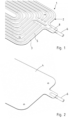
- the Figures 1 to 6 serve to explain a first embodiment of a heat exchanger plate 1.
- FIG. 6 A second embodiment of a cooling plate 1 is explained.
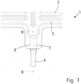
- the cross-sectional view in the Figure 6 applies to both embodiments of the cooling plate 1.
- the Figure 14 serves to explain a further embodiment of a cooling plate 1 and the configuration of the connection for a cooling fluid line.
- the heat exchanger plate 1 is in particular a cooling plate for battery cooling, in particular for a vehicle battery of a motor vehicle.
- the heat exchanger plate 1 has a plate body 2 formed from two plate elements 3, 4.
- the plate element 3 is a channel plate which has a channel structure consisting of at least one channel 5 (see in particular Figures 1 , 5 and 11).
- the plate element 4 is a completely or almost completely flat floor plate (see Figure 2 ).
- the two plate elements 3, 4 are positioned flat on top of each other and form a plate stack.
- the adjacent surfaces of the plate elements 3, 4 are provided with a solder material either completely or in certain areas.
- a solder material is pre-applied in the form of a plated solder layer on one of the plate elements 3, 4.
- connection piece 6 for a cooling fluid is connected to the plate body 2.
- the connection piece 6 serves to supply or drain a cooling fluid.
- one connection piece 6 is provided for supplying a cooling fluid, whereas a cooling fluid is drained via another connection piece 6.
- the connecting piece 6 has a connecting section 7 which is fitted into a receiving section 8 of the plate body 2 formed between the plate elements 3, 4.
- connection section 7 has an elliptical outer contour in cross-section.
- connection section 7 of the connection piece 6 has a main axis H in cross-section as well as a secondary axis N perpendicular to it.
- the main axis H corresponds to the central transverse axis and describes the largest dimension of the connection section 7.
- the main axis H extends in the joining plane FE of the plate elements 3, 4.
- the secondary axis N is the smallest dimension of the connection section 7 in the radial outward direction.
- connection section 7 has two outward-facing longitudinal webs 9.
- the longitudinal webs 9 are located opposite each other on the main axis H of the connection piece 6.
- the longitudinal webs 9 are made of the same material and are an integral part of the connection section 7 and from the inside of the connection piece 6 to the outside.
- connection section 7 of the connection piece 6 lies in the receiving section 8 of the plate body 2 and is joined to it in a material-locking manner.
- the receiving section 8 has longitudinal grooves 10 extending between the plate elements 3, 4 in the area of the joining plane FE.
- the longitudinal webs 9 of the connection section 7 run in the longitudinal direction L of the receiving section 8 in the longitudinal grooves 10.
- the longitudinal webs 9 and the longitudinal groove 10 are designed to complement each other. This means that the contour of the longitudinal grooves 10 and the contour of the longitudinal webs 9 complement each other to form a joint gap 11.
- the longitudinal webs and the longitudinal grooves work together in a tongue and groove manner.
- the longitudinal webs 9 are triangular in cross-section and have web walls 12 which are concavely curved and end in a rounded tip 13 (see in particular Figure 6 ).
- the longitudinal grooves 10 are configured in a funnel-shaped cross-section with concave groove cheeks 14 and a wedge-shaped groove base 15. In this respect, particular attention is also drawn to the representation of the Figure 6 to refer to.
- the specifications convex and concave refer to the center point M of the connection piece 6.
- the connecting section 7 has a convexly curved upper wall section 16 and a convexly curved lower wall section 17.
- the longitudinal webs 9 adjoin the wall sections 16, 17 on both sides.
- the wall sections 16, 17 merge into the web walls 12 of the longitudinal webs 9.
- the receiving section 8 has convexly curved receiving wall sections 18, 19, each of which merges into a throat cheek 14.
- connection section 7 is joined in the receiving section 8 by a solder material 20 applied in the joint gap 11.
- a solder material 20 is placed around the connection section 7 of the connection piece 6.
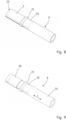
- the Figure 3 shows the Connection piece 6 without and the Figure 4 with applied solder material 20.
- the solder material 20 is melted, the joint gap 11 is completely wetted and filled with solder material 20 and the components are joined in a material-tight manner.
- the cross-sectional contour of the connecting section 7 can be described as a lemon shape, whereby the cross-sectional specification refers to a longitudinal section through a lemon.
- connection section 7 and the inner contour of the receiving section 8 are designed to be complementary to one another, forming the joint gap 11.
- a stop is provided in the form of an annular bead 21.
- the annular bead 21 is formed from the wall of the connecting piece 6 by compression and shear pressure forming.
- the connecting piece 6 is drawn in a constriction area 22, to which the annular bead 21 is connected, turned outwards.
- the connecting section 7 is connected to the annular bead 21.
- the connecting section 7 is configured as previously described and in particular in the Figure 6 shown.
- connection piece 6 which protrudes from the plate body 2, is designed as a coupling section 24 and serves to connect a cooling fluid line, which can be fixed to the coupling section 24.
- an abutment body is provided in the coupling section 24, which is designed in the form of an annular bead 25.
- the annular bead 25 is formed from the wall of the coupling section 24.
- a cooling fluid line in particular a cooling fluid hose, can be connected to the coupling section 24 and the Abutment body in the form of the annular bead 25 is pushed on and fixed by means of a suitable fastening means, for example a spring clamp.
- the coupling section 24 of the connecting piece 6 is circular in cross section. In the embodiment of the connecting piece 6, as shown in the Figures 3 and 4 As shown, the circular cross-section of the coupling section 24 continuously transitions via a transition section 26 into the connection section 7 and its cross-sectional configuration.
- connection section 7 in the receiving section 8 For the material-locking joining of the connection section 7 in the receiving section 8, a solder material 20 in the form of a solder sleeve or a solder strip is applied to the connection section 7.
- the connection piece 6 is positioned with the connection section 7 in the receiving section 7 of the plate body 2 and is connected to it by form soldering.
- a connecting piece 6 is provided, on which a connecting section 7 with two outward-facing longitudinal webs 9 and curved, rounded wall sections 16, 17 is formed. Furthermore, a first and a second plate element 3, 4 are provided. The two plate elements 3, 4 are flat. At least one of the plate elements 3, 4 is provided with a solder material. Each plate element 3, 4 has a protruding mold section 27. A receiving contour for the connecting section 7 of the connecting piece 6 is molded into each of the mold sections 27. A plate stack is formed from the two plate elements 3, 4, the connecting section 7 of the connecting piece 6 being arranged between the mold sections 27 and the receiving contours provided there. A solder material 20 is applied to the connecting section 7.
- the plate elements 3, 4 are transferred to a heated form soldering tool.
- a plate stack can be formed from the two plate elements with a connecting piece 6 integrated between them outside the form soldering tool.
- the plate stack can also be formed in the form soldering tool.
- the plate stack or the plate elements 3, 4 and the connecting piece 6 with the positioned connecting section 7 are placed in the heated form soldering tool inserted.
- the connecting piece 7 of the connecting piece 6 is arranged between the plate elements 3, 4 in the receiving contours that complement each other to form a receiving section 8.
- the form soldering tool has a lower tool and an upper tool. By closing the form soldering tool, the plate stack is clamped between the upper tool and the lower tool and heated.
- the plate stack lies with its underside in surface contact with the lower tool and with its top in surface contact with the upper tool.
- the form sections 27 are finally formed in the area of the receiving contours of the plate elements 3, 4 and shaped to the outer contour of the connection section 7. This creates a joint gap 11 into which the solder material 20 is pressed.
- the formed form sections 27 complement each other to form the receiving section 8 with longitudinal grooves 10 that securely extend in the area of the joining plane FE between the plate elements 3, 4.
- the plate stack clamped between the lower tool and the upper tool is heated.
- a gap between the plate elements 3, 4 is subjected to internal pressure. This is done by introducing an active medium, usually nitrogen, into a gap between the plate elements 3, 4.
- a plate element area of the upper plate element 3, which forms the channel plate is formed into a channel cavity in the upper tool. Channel sections of the channel 5 run into one another in a loop shape and communicate between the connection piece 6 shown here and another connection piece not shown.
- the plate stack can be sealed all the way along adjacent edge areas and/or adjacent to the channel cavity and in particular in the area of the receiving section of the plate elements 3, 4 by means of one or more pressure elements.
- Pressure elements can be provided as sealing strips in the upper tool and/or lower tool and are intended for and determine the plate stack or the two plate elements 3, 4 all the way along the outer edge areas and adjacent to the channel cavity and the Receiving section 8 with the connection section 7 of the connection piece 6 received therein is to be sealed.
- Pressure elements can be implemented, for example, in the form of bead-shaped bodies.
- solder material applied between the plate elements 3, 4 and the solder material 20 applied between the receiving section 8 and the connection section 7 melts or has melted when the plate elements 3, 4 are heated up. A material bond is formed between the joining partners.
- the cooling plate 1 can be held in the form soldering tool and cooled after it has been opened and before it is removed. To do this, the channel plate 1 can be lifted off the lower tool by manipulator elements during or after the form soldering tool has been opened, so that the contact between the lower tool and the still warm channel plate is eliminated. The upper tool is opened and is also no longer in contact with the cooling plate. After a holding or cooling time, the cooling plate 1 is then also removed from the form soldering tool.
- solder stop means 28 can be integrated into the arrangement of connection piece 6 and receiving section 8.
- the solder stop means 28 can be formed by the annular bead 21, which rests on the front side against the opening 29 of the receiving section 8.
- the solder stop means 28 is formed by a layer, a ring or a sleeve made of a sealing metal material 30. Such embodiments are shown in the illustrations of the Figures 12 and 13
- the solder stop means 28 is made of a sealing metal 30 which has a higher melting temperature than the solder material 20 of the first type.
- the solder stop means 28 is arranged in the region of the opening 29 of the connection section 8 in the interior of the receiving section 8 in front of the solder material 20.
- solder stop means 28 is arranged in the region of the opening 29 between the annular bead 21 and the solder material 20.
- the sealing metal 30 can also be a second type of solder material that has a higher melting temperature than the first type of solder material 20. Due to the higher melting temperature of the first type of solder material, it becomes viscous and plastically deformable under the influence of temperature in the form soldering tool, so that a full-surface sealing effect is achieved in the intended area of the form soldering joint between the connection piece 6, connection section 7 and receiving section 8.
- the Figure 14 shows a section of a plate body 2 with a view of a plate element 3 and the receiving section 8 formed in the mold section 27.
- the connection section 7 of the connection piece 8 is positioned in the receiving section 8.
- connection section 7 is configured in cross-section as shown in the Figure 6 explained.
- connection section 7 tapers via a transition section 31 into a longitudinal section 32.
- connection piece 6 is circular.
- the receiving section 8 also has two length sections 33, 34 with different cross sections.
- a length section 33 on the plate body side is configured as shown in the Figure 6 described.
- a solder material 20 is applied to the connection section 7.
- the cross-sectional change in the connection section 7 and in the receiving section 8 forms a solder stop 28.
- the solder stop 28 formed by the cross-sectional change in the transition from the connection section 7 to the longitudinal section 32 and in the transition from the longitudinal section 33 to the longitudinal section 34 of the receiving section 8
- the solder stop means 28 designed as a solder stop means limits the flow of solder when producing the solder connection between the connection piece 6 or the connection section 7 and the receiving section 8.
Landscapes
- Engineering & Computer Science (AREA)
- Mechanical Engineering (AREA)
- Manufacturing & Machinery (AREA)
- Chemical & Material Sciences (AREA)
- Chemical Kinetics & Catalysis (AREA)
- Electrochemistry (AREA)
- General Chemical & Material Sciences (AREA)
- Physics & Mathematics (AREA)
- Thermal Sciences (AREA)
- General Engineering & Computer Science (AREA)
- Heat-Exchange Devices With Radiators And Conduit Assemblies (AREA)
- Secondary Cells (AREA)
Abstract
Description
- Die Erfindung betrifft eine Wärmeübertragerplatte sowie ein Verfahren zur Herstellung von Wärmeübertragerplatten.
- Wärmeübertragerplatten kommen für unterschiedlichste Anwendungen zum Einsatz. Bei einer Wärmeübertragerplatte der vorliegend in Rede stehenden Art handelt es sich insbesondere um eine Kühlplatte zur Batteriekühlung von Kraftfahrzeugen.
- Die gesteigerten Anforderungen an Elektrofahrzeuge bezüglich Reichweite, Fahrleistung und Ladezeit haben zur Folge, dass die thermischen Belastungen der Batterien durch Überhitzung bzw. Alterung zunehmen. Um diese schädlichen Effekte zu reduzieren, wird mittels von Medien durchflossenen Temperierelementen die Betriebstemperatur einer Batterie begrenzt. Bei den Temperierelementen handelt es sich um Wärmeübertragerplatten in Form von Kühlplatten, die oberhalb, seitlich und/oder unterhalb eines Batteriemoduls angeordnet werden.
- Wärmeübertragerplatten herkömmlicher Bauart bestehen üblicherweise aus gefügten Aluminiumblechen oder stranggepressten Aluminiumprofilen, die über Anschlussstutzen das Durchströmen der Wärmeübertragerplatten mit Temperiermedium bzw. Kühlfluid ermöglichen. Meist werden die Anschlussstutzen formgebend oder spanabhebend gefertigt und mit dem Plattenkörper einer Kühlplatte verbunden. Die Anschlussstutzen sind so konzipiert, dass sie eine schnelle Montage von Kühlfluidleitungen ermöglichen.
- Durch die
EP 2 372 761 B1 zählt eine Kühlplatte mit einem aus zwei Plattenelementen gebildeten Plattenkörper zum Stand der Technik, bei der Fluidanschlüsse bzw. Anschlussstutzen für Kühlfluid an einer ebenen Fläche eines Plattenelements parallel zur Fläche des Plattenelements angeordnet sind. - Bei der aus der
EP 2 607 832 A1 bekannten Kühlplatte erfolgt die Zuleitung und Ableitung von Kühlfluid über Verbinderstücke, die mit einem Anschlussabschnitt in eine Aufnahme am Plattenelement einsteckbar sind. - Auch bei der in der
EP 3 741 876 A1 beschriebenen Batteriekühlplatte ist der Plattenkörper aus zwei Plattenelementen gebildet und weist Anschlussstutzen für Kühlfluid auf, wobei ein Anschlussstutzen parallel zur Ebene der Plattenelemente ausgerichtet und mit einem Anschlussabschnitt in einem Aufnahmeabschnitt des Plattenkörpers gefügt ist. - Die
DE 10 2010 051 106 B4 offenbart eine Kühlplatte, die mindestens einen Kühlkanal zur Leitung eines Kühlmittels aufweist, der mit zumindest einem Einlass und zumindest einem Auslass versehen ist. Die Kühlplatte weist zumindest zwei flächig aneinander anliegenden Plattenelemente auf, in denen Ausbuchtungen ausgeformt sind, die miteinander einen Kühlkanal ausbilden. Der Einlass und der Auslass sind jeweils mit einem Anschlussstutzen versehen zur Verbindung des Kühlkanals mit einer Kühlmittelanschlusseinheit. - Der Erfindung liegt ausgehend vom Stand der Technik die Aufgabe zugrunde, eine funktional und herstellungstechnisch verbesserte Wärmeübertragerplatte zu schaffen sowie ein Verfahren zur Herstellung einer Wärmeübertragerplatte aufzuzeigen, welches eine montagegerechte, prozesssichere und günstige Fügung eines Anschlussstutzens an dem Plattenkörper einer Wärmeübertragerplatte gewährleistet.
- Die Lösung des gegenständlichen Teils der Aufgabe besteht in einer Wärmeübertragerplatte gemäß den Merkmalen von Anspruch 1.
- Der verfahrensmäßige Teil der Aufgabe wird durch ein Verfahren nach Anspruch 11 gelöst.
- Vorteilhafte Ausgestaltungen und Weiterbildungen der Erfindung sind Gegenstand der anhängigen Ansprüche.
- Eine Wärmeübertragerplatte weist einen aus zwei Plattenelementen gebildeten Plattenkörper und Anschlussstutzen für die Zuleitung und Ableitung eines Kühlfluids auf. Bei den Plattenelementen handelt es sich insbesondere um eine Kanalplatte und eine Bodenplatte, welche zu einem Plattenstapel zusammengeführt und miteinander gefügt den Plattenkörper bilden. Mit dem Plattenkörper sind die Anschlussstutzen gefügt. Zumindest ein Anschlussstutzen besitzt einen Anschlussabschnitt, der in einem, zwischen den Plattenelementen ausgebildeten Aufnahmeabschnitt des Plattenkörpers gefügt ist. Die Ausrichtung des Anschlussabschnitts des Anschlussstutzens ist parallel zur Ebene der Plattenelemente. Außerhalb des Plattenkörpers kann der Anschlussstutzen Bogen- und/oder Krümmungsabschnitte aufweisen. Der außerhalb des Plattenkörpers verlaufende Teil des Anschlussstutzens ist als Koppelabschnitt zum Anschluss einer Anschlussleitung für ein Kühlfluid konfiguriert.
- Die Plattenelemente bestehen aus Leichtmetall oder einer Leichtmetalllegierung, insbesondere einer Aluminiumlegierung.
- Zumindest ein Plattenelement des Plattenkörpers der Kühlplatte weist eine Kanalstruktur zur Durchleitung eines Kühlfluids auf.
- Erfindungsgemäß weist der Anschlussabschnitt zwei nach außen gerichtete Längsstege und der Aufnahmeabschnitt weist sich im Bereich der Fügeebene zwischen den Plattenelementen erstreckende Längskehlen auf, wobei die Längsstege in den Längskehlen verlaufen.
- Die Plattenelemente sind unter Eingliederung des Anschlussabschnitts des Anschlussstutzens im Aufnahmeabschnitt des Plattenkörpers löttechnisch gefügt. Die Längsstege und die Längskehlen ergänzen einander komplementär. Die Kontur bzw. Konfiguration der Längsstege und der Längskehlen stellt einen technologisch notwendigen Fügespalt sicher. Die Fügeflächen sind optimiert. Der Fügespalt, insbesondere die Breite des Fügespalts, ist über den Umfang bzw. den Verlauf zwischen Anschlussabschnitt und Aufnahmeabschnitt vergleichmäßigt ohne Dickensprünge. Die Spaltbreite ist klein. Eine hochfeste, dichte, stoffschlüssige Fügung des Anschlussstutzens mit seinem Anschlussabschnitt im Aufnahmeabschnitt des Plattenkörpers wird erreicht.
- Der Anschlussabschnitt weist zwei konvex gekrümmte Wandabschnitte auf, die sich zwischen den Längsstegen erstrecken. Insbesondere sind die Wandabschnitte elliptisch bzw. ellipsenabschnittsförmig gekrümmt.
- Die beiden gekrümmten Wandabschnitte verlaufen spiegelsymmetrisch zu einer Querachse des Anschlussabschnitts, insbesondere der Mittellängsachse, und gehen jeweils endseitig in einen Längssteg über. Die Wandabschnitte sind konvex gekrümmt zum Mittelpunkt bzw. der Mittellängsachse des Anschlussabschnitts. In den Stegabschnitten sind die Seitenflächen konkav gekrümmt.
- Eine Ausgestaltung des Anschlussabschnitts sieht vor, dass der Anschlussabschnitt des Anschlussstutzens im Querschnitt eine elliptische bzw. ellipsenförmige Außenkontur auf mit auf einer Querachse einander gegenüberliegenden nach außen gerichteten Längsstegen.
- Möglich ist es, dass der Anschlussabschnitt im Querschnitt abgeflachte obere und untere Wandabschnitte, insbesondere Mittelwandabschnitte, besitzt, welche jeweils endseitig über konvex gekrümmte Wandabschnitte in einen Längssteg übergeben.
- Der Aufnahmeabschnitt des Plattenkörpers bildet einen Einsteck- bzw. Fügebereich für den Anschlussabschnitt des Anschlussstutzens.
- Der Anschlussstutzen weist im Anschlussabschnitt beidseitig sich in Längsrichtung des Anschlussstutzens erstreckende Längsstege auf. Diese sind im Querschnitt dreieckförmig konfiguriert mit konkaven Stegwänden und einer gerundeten Spitze. Die Kontur der Längsstege gewährleistet einen fließenden Übergang von der elliptischen Außenkontur zu den Längsstegen mit gerundeten Außenflächen ohne Stufen oder scharfe Krümmungen bzw. Abwinkelungen.
- Die Längskehlen des Aufnahmeabschnitts sind im Querschnitt trichterförmig konfiguriert mit bezogen auf den Mittelpunkt bzw. die Mittellängsachse des Anschlussstutzens und des Aufnahmeabschnitts konkaven Kehlwangen und einem keilförmigen Kehlgrund. Die Innenkontur im Bereich der durch die Kehlwangen gebildeten Innenecke des Aufnahmeabschnitts ist entlang der Kehlwangen gerundet. Der Kehlgrund am Übergang des Aufnahmeabschnitts zu den einander kontaktierenden Plattenelementen ist spitzwinklig.
- Die Konfiguration der Längsstege und der Längskehlen sind zueinander komplementär ausgebildet. Die Konturen von Längssteg und Längskehle ergänzen einander derart, dass die Längsstege in die Längskehlen nach Art einer Nut/Feder-Verbindung zusammenwirken, wobei zwischen den Konturen ein Fügespalt ausgebildet ist.
- Der Anschlussabschnitt weist zwei konvex gekrümmt verlaufende Wandabschnitte auf. Diese erstrecken sich jeweils zwischen den einander gegenüberliegenden Längsstegen und gehen in die konkaven Stegwände über.
- Der Aufnahmeabschnitt weist konvex gekrümmt verlaufende Innenwandabschnitte auf, an welche sich die konkaven Kehlwangen anschließen.
- Die Angaben "konvex" und "konkav" beziehen sich jeweils auf den Mittelpunkt bzw. die Längsachse des Anschlussstutzens. Eine konvexe Fläche, eine konvexe Wand oder ein konvexer Wandabschnitt ist eine vom Mittelpunkt bzw. der Mittellängsachse des Anschlussstutzens nach außen gewölbte Fläche bzw. Abschnitt.
- Eine konkave Fläche, ein konkaver Wandabschnitt oder eine konkave Kehlwange ist ein oder eine in Bezug auf den Mittelpunkt bzw. die Mittellängsachse des Anschlussabschnitts nach innen gewölbte oder gekrümmt verlaufende Fläche, Abschnitt oder Wange.
- Im Querschnitt sind der Anschlussabschnitt des Anschlussstutzens ebenso wie der Aufnahmeabschnitt spiegelsymmetrisch zur horizontalen Mittelquerachse und zur vertikalen Mittelquerachse ausgestaltet.
- Die Querschnittskontur des Anschlussabschnitts kann als Zitronenform bzw. zitronenförmig beschrieben werden, wobei die Querschnittsangabe auf einen Längsschnitt durch eine Zitrone bezogen ist. Das bedeutet, der Anschlussabschnitt ist ellipsenförmig konfiguriert und weist im Querschnitt eine Hauptachse sowie eine Nebenachse auf. Die Hauptachse und die Nebenachse stehen senkrecht aufeinander und schneiden sich im Mittelpunkt entlang der Mittelachse des Anschlussstutzens. Die Hauptachse beschreibt die größte Abmessung des Anschlussstutzens im Anschlussabschnitt, wohingegen die Nebenachse die kleinste Abmessung des Anschlussabschnitts in radialer Richtung nach außen beschreibt. Bezogen auf die Fügeebene der Plattenelemente des Plattenkörpers erstreckt sich die Hauptachse in der Fügeebene und entspricht der horizontalen Mittelquerachse. Die Nebenachse entspricht der vertikalen Mittelquerachse.
- Der Querschnitt des Anschlussstutzens im Anschlussabschnitt ist symmetrisch bezüglich der Hauptachse und der Nebenachse.
- Die Längsstege liegen auf der Hauptachse einander gegenüber und sind nach außen aus der Wand des Anschlussstutzens geformt.
- Wie erläutert, sind die Längsstege im Querschnitt insbesondere dreieckförmig ausgeformt mit gerundeten, konkaven Stegwänden und einer gerundeten Spitze. Die gerundete Spitze bildet die Kuppe eines Seitenstegs.
- Zwischen dem Anschlussabschnitt des Anschlussstutzens und dem Aufnahmeabschnitt des Plattenkörpers ist ein Fügespalt ausgebildet. Durch die konturnahe Ausformung der Stutzengeometrie des Anschlussstutzens und des Aufnahmeabschnitts und deren Abstimmung aufeinander, ist ein technologisch notwendiger und vorteilhafter Fügespalt sichergestellt. Besonders vorteilhaft ist, dass der Fügespalt im Querschnitt in seinem Umfangsverlauf eine geringe bzw. kleine Breite hat, die auf dem überwiegenden Teil der Umfangslänge des Fügespalts gleichmäßig klein ist. Auch im Bereich zwischen den Spitzen der Längsstege und dem keilförmigen Kehlgrund einer Längskehle ist der Lötspalt klein.
- Zwischen Anschlussabschnitt und Aufnahmeabschnitt ist ein Lotwerkstoff appliziert. Die Plattenelemente untereinander sowie die Plattenelemente und der Anschlussstutzen sind löttechnisch gefügt. Dies ist herstellungstechnisch und prozesssicher sowie kostengünstig zu realisieren. Die löttechnische Fügung der Bauteile erfolgt in einem Formlötwerkzeug, in welchem die Plattenelemente an den Fügeflächen aneinander gepresst, der Aufnahmeabschnitt des aus den beiden Plattenelementen gebildeten Plattenkörpers endgeformt, der Kanal im Plattenkörper ausgebildet wird und die Bauteile auf Löttemperatur erwärmt und löttechnisch miteinander gefügt werden.
- Im Formwerkzeug erfolgt ein kombiniertes Formen und Löten. Im Formlötwerkzeug wird der Kanal und die Kanalstruktur im Plattenkörper geformt, der Anschlussabschnitt des Plattenkörpers endgeformt sowie die Plattenelemente untereinander und die Plattenelemente bzw. der Aufnahmeabschnitt und der Fügeabschnitt des Anschlussstutzens miteinander verlötet. Beim Lötvorgang sind die Bauteile im Formlötwerkzeug eingespannt und aneinander gepresst.
- Ein Aspekt der Erfindung nutzt die Umformeigenschaften des duktilen Lotwerkstoffs zur Abdichtung des Anschlussstutzens im Aufnahmeabschnitt. Der Anschlussabschnitt des Anschlussstutzens wird zumindest endkonturnah vorgeformt. Hierbei erhält der Anschlussabschnitt seine Querschnittskonfiguration mit zwei auf einer Querachse nach außen gerichteten Längsstegen und den bogenförmig gekrümmt verlaufenden Wandabschnitten, die sich zwischen den Längsstegen erstrecken. Die Formgebung des Anschlussstutzens erfolgt umformtechnisch unter Nutzung eines Innendorns.
- Auf den Anschlussabschnitt des Anschlussstutzens ist ein Lotwerkstoff appliziert. Der Lotwerkstoff im Bereich zwischen Anschlussabschnitt und Aufnahmeabschnitt kann vorappliziert auf die beiden Formabschnitte der Plattenelemente bzw. den Anschlusskonturen sein. Eine vorteilhafte Ausgestaltung und Vorgehensweise sieht vor, dass ein Lotwerkstoff in den Anschlusskonturen oder auf dem Anschlussabschnitt appliziert wird, beispielsweise in Form von Lotwerkstofflagen oder Lotwerkstoffhülsen. Wie bereits erwähnt, kann hierfür Lotwerkstoff in geeigneter Menge auf den Formabschnitten und den Anschlusskonturen der Plattenelemente vorappliziert sein. Der Lotwerkstoff wird beispielsweise in Form eines Lotstreifens oder einer Lothülse aus einem niedrigschmelzenden Lotwerkstoff, insbesondere einem Lotwerkstoff auf Aluminiumbasis, auf dem Anschlussabschnitt aufgebracht sein bzw. werden.
- Die Plattenelemente werden in ein beheizbares Formlötwerkzeug überführt, welches ein Oberwerkzeug und ein Unterwerkzeug besitzen. Hierzu kann außerhalb des Formlötwerkzeugs ein Plattenstapel aus den beiden Plattenelementen gebildet werden, wobei der Anschlussstutzen mit seinem Anschlussabschnitt bereits zwischen die Formabschnitte der Plattenelemente in den Anschlusskonturen positioniert werden kann. Dieser Plattenstapel wird dann in das Formlötwerkzeug überführt.
- Ein Plattenstapel mit eingegliedertem Anschlussstutzen kann auch im Formlötwerkzeug gebildet werden. Hierzu werden die Plattenelemente unter Eingliederung des Anschlussstutzens im Formlötwerkzeug positioniert. Im Formlötwerkzeug ist der Anschlussabschnitt zwischen Formabschnitten der Plattenelemente und den dort vorgesehenen Anschlusskonturen positioniert. Die Formabschnitte können an vom Grundkörper der Plattenelemente vorstehenden Platinenabschnitten der Plattenelemente ausgebildet sein.
- Beim Schließen des Formlötwerkzeugs wird der aus den beiden Plattenelementen gebildete Plattenstapel mit dem eingegliederten Anschlussabschnitt des Anschlussstutzens im Formlötwerkzeug eingeklemmt. Hierbei werden die Anschlusskonturen in den Formabschnitten der Plattenelemente um den Anschlussabschnitt des Anschlussstutzens endgeformt. Die Formabschnitte der Plattenelemente werden endgeformt und bilden den Aufnahmeabschnitt. Die Außenkontur des Anschlussabschnitts gibt die Innenkontur des Aufnahmeabschnitts vor. Die umgeformten Formabschnitte ergänzen sich zum Aufnahmeabschnitt. Der Aufnahmeabschnitt weist konvex gekrümmt verlaufende Innenwandabschnitte auf. Im Bereich der Fügeebene zwischen den Plattenelementen werden sich in Längsrichtung des Aufnahmeabschnitts erstreckende Längskehlen gebildet. Die Längskehlen sind im Querschnitt trichterförmig konfiguriert und weisen konkave Kehlwangen und einen keilförmigen Kehlgrund auf. Die Kehlwangen schließen sich an die gekrümmt verlaufenden Innenwandabschnitte des Aufnahmeabschnitts an.
- Beim Formvorgang und der Ausbildung der Kontur des Aufnahmeabschnitts im Formlötwerkzeug wird der um den Anschlussstutzen applizierte Lotwerkstoff radial gestaucht und so verpresst, dass der duktile Lotwerkstoff in den sich bildenden Fügespalt zwischen Anschlussabschnitt und Aufnahmeabschnitt fließt.
- Im Formlötwerkzeug eingespannt wird ein Zwischenraum zwischen den Plattenelementen des Plattenstapels mit Innendruck beaufschlagt. Dies erfolgt durch Einleiten eines Wirkmediums über den Anschlussstutzen. Durch innendrucktechnische Umformung wird zumindest ein Kanal in zumindest einem Plattenelement ausgebildet.
- In Folge der Erwärmung der Plattenelemente bzw. des im Formlötwerkzeug eingespannten Plattenstapels wird der Lotwerkstoff zwischen den Plattenelementen und zwischen dem Anschlussabschnitt und dem Aufnahmeabschnitt aufgeschmolzen und die Bauteile stoffschlüssig gefügt.
- Eine vorteilhafte Ausgestaltung sieht vor, dass der Anschlussstutzen einen Anschlag aufweist. Insbesondere ist ein Anschlag in Form einer Ringwulst ausgeführt. Der Anschlag bzw. die Ringwulst liegt stirnseitig am Anschlussstutzen an. Durch den Anschlag der stirnseitig am Anschlussstutzen zur Anlage gelangt, wird die Position des Anschlussstutzens in axialer Einführrichtung relativ zum Plattenkörper bestimmt. Weiterhin erfolgt eine axiale Abdichtung durch den Anschlag bzw. die Ringwulst an der Öffnung des Anschlussstutzens.
- Eine weitere vorteilhafte Ausführungsform der erfindungsgemäßen Wärmeübertragerplatte sieht vor, dass ein Lotstoppmittel vorgesehen ist, welches den Lotfluss bei der Herstellung der Lötverbindung begrenzt. Das Lotstoppmittel ist zwischen dem Anschlussstutzen und dem Aufnahmeabschnitt angeordnet, insbesondere ist das Lotstoppmittel zwischen dem Anschlussabschnitt des Anschlussstutzens und dem Aufnahmeabschnitt angeordnet.
- Eine Ausführungsform sieht vor, dass öffnungsseitig des Aufnahmeabschnitts ein Lotstoppmittel angeordnet ist. Öffnungsseitig bedeutet, dass das Lotstoppmittel im Bereich der Öffnung des Aufnahmeabschnitts innen im Aufnahmeabschnitt oder außen stirnseitig um die Öffnung des Aufnahmeabschnitts herum appliziert ist.
- Eine für die Praxis besonders vorteilhafte Ausgestaltung sieht vor, dass das Lotstoppmittel durch eine Querschnittsveränderung im Anschlussabschnitt des Anschlussstutzens und im Aufnahmeabschnitt ausgestaltet ist. Das Lotstoppmittel ist durch die Querschnittsveränderung im Fügebereich zwischen dem, in den Formabschnitten der Plattenelemente ausgebildeten Aufnahmeabschnitt und dem Anschlussstutzen ausgebildet. Sowohl der Anschlussabschnitt als auch der Aufnahmeabschnitt weisen zwei Längenabschnitte mit voneinander verschiedenen Querschnitten auf. Die Längenabschnitte des Anschlussabschnitts, ebenso wie die Längenabschnittes des Aufnahmeabschnitts gehen über einen Verjüngungsabschnitt ineinander über.
- Die Querschnittsveränderung im Anschlussabschnitt und im Aufnahmeabschnitt ergänzen einander und es kommt zu einer Querschnittsverringerung des Ringraums zwischen Anschlussabschnitt und Aufnahmeabschnitt. Der beim Lötvorgang schmelzflüssige Lotwerkstoff wird in der Querschnittsveränderung zwischen Anschlussabschnitt und Aufnahmeabschnitt aufgehalten. Hierdurch wird der Lotfluss bei der Herstellung der Lötverbindung begrenzt.
- Eine optional zusätzliche oder alternative Ausführungsform sieht vor, dass das Lotstoppmittel aus einem Dichtmetall gebildet ist. Das Dichtmetall wird unter der Temperatureinwirkung im Formlötwerkzeug weich und dickflüssig. Es entsteht eine fließfähige, homogene Dichtmasse, die unter dem Druck im Formlötwerkzeug ein Fließen des geschmolzenen Lötwerkstoffs in unerwünschte bzw. technologisch nachteilige Bereiche verhindert. Das Dichtmetall weist eine höhere Schmelztemperatur auf als der für den Formlötvorgang eingesetzte Lotwerkstoff.
- Das Lotstoppmittel ist dafür eingerichtet und bestimmt, den Lotfluss bei der Herstellung der Lötverbindung zu begrenzen. Auch ist das Lotstoppmittel dafür eingerichtet und bestimmt sowie positioniert, dass ein Ausblasen des während der Innendruckumformung der Plattenelemente zur Ausbildung des Kanals noch schmelzflüssigen Lotwerkstoffs zu verhindern.
- Ein Lotstoppmittel kann auch aus einem Lotwerkstoff gebildet sein. Es werden folglich zwei Lotwerkstoffe mit unterschiedlichen Werkstoffeigenschaften appliziert. Ein Lotwerkstoff erster Art ist der Lotwerkstoff, der auf bzw. um den Anschlussabschnitt des Anschlussstutzens appliziert ist. Ein Lotwerkstoff zweiter Art weist eine gegenüber dem Lotwerkstoff erster Art höhere Schmelztemperatur auf und bildet das Lotstoppmittel. Der Lotwerkstoff zweiter Art schmilzt beim Erwärmen des Anschlussstutzens und des Aufnahmeabschnitts im Warmformwerkzeug später und ist unter der Temperatureinwirkung des Warmformwerkzeugs zäher als der Lotwerkstoff erster Art und damit dickflüssiger bzw. höher viskos. Auf diese Weise bildet der Lotwerkstoff zweiter Art ein Lotstoppmittel für den Lotwerkstoff erster Art.
- Das Lotstoppmittel kann auch anders realisiert sein, beispielsweise in Form einer mechanischen Lotstoppsperre, insbesondere eines Lotstopprings. Auch die äußere Ringwulst, die stirnseitig am Aufnahmeabschnitt anliegt, kann die Öffnung lotwerkstoffabdichtend verschließen.
- Es können auch zwei verschiedene Lotstoppmittel bzw. Arten von Lotstoppmitteln in Kombination eingesetzt werden. So kann ein Lotstoppmittel in Form einer Querschnittsveränderung im Anschlussabschnitt des Anschlussstutzens und einer komplementär dazu gestalteten Querschnittsveränderung im Aufnahmeabschnitt vorgesehen sein. Weiterhin kann ein Lotstoppmittel vorgesehen sein in Form einer mechanischen Lotstoppsperre, insbesondere einem separaten Ringkörper aus einem Lotstoppwerkstoff oder einem im Anschlussstutzen materialeinheitlich einstückig ausgebildeten Lotstoppring.
- Der Anschlussstutzen weist den Anschlussabschnitt auf, über den die Fügung im Aufnahmeabschnitt des Plattenkörpers erfolgt. Einlaufseitig weist der Anschlussstutzen einen Koppelabschnitt auf. Der Koppelabschnitt dient zum Anschluss einer Kühlfluidleitung. Im Koppelabschnitt besitzt der Anschlussstutzen einen kreisrunden Querschnitt. Vom kreisrunden Querschnitt im Koppelabschnitt geht der Anschlussstutzen über einen Übergangsabschnitt in den Anschlussabschnitt über.
- Eine die praktische Ausgestaltung weiter verbessernde Ausführungsform sieht vor, dass der Anschlussstutzen einen Koppelabschnitt aufweist mit einem Widerlager. Das Widerlager fungiert zum Anschluss einer Anschlussleitung für ein Kühlfluid. Der Widerlagerkörper ist bevorzugt in Form einer Ringwulst im hinteren Koppelabschnitt ausgebildet. Die Ringwulst ist werkstoffeinheitlich einstückiger Bestandteil des Koppelabschnitts.
- Dem Anschlussabschnitt vor- und/oder nachgelagert kann ein Stutzenabschnitt vorgesehen sein, mit einem anderen Querschnitt als der vom Anschlussabschnitt, beispielsweise mit einem runden oder elliptischen Querschnitt ohne Längsstege.
- Eine für die Praxis vorteilhafte Ausführungsform sieht vor, dass der Anschlussabschnitt des Anschlussstutzens zwei Längenabschnitte aufweist, wobei die beiden Längenabschnitte einen voneinander verschiedenen Querschnitt besitzen. Ein erster bzw. vorderer plattenkörperseitiger Längenabschnitt besitzt eine größere Querschnittsfläche als ein zweiter bzw. hinterer Längenabschnitt des Anschlussabschnitts. Der vordere bzw. erster Längenabschnitt besitzt die Querschnittskonfiguration mit seitlichen Längsstegen. Der erste Längenabschnitt und der zweite Längenabschnitt sind über einen Übergangs- bzw. einem Verbindungsabschnitt miteinander verbunden.
- Komplementär zur Ausgestaltung der Längenabschnitte des Anschlussabschnitts ist der Aufnahmeabschnitt gestaltet. Auch der Aufnahmeabschnitt weist einen vorderen plattenkörperseitigen Längenabschnitt auf. Dieser weist eine andere Querschnittskonfiguration auf als ein sich über einen Übergang anschließender zweiter hinterer Längenabschnitt des Aufnahmeabschnitts. Die Querschnittsfläche des vorderen ersten Längenabschnitts des Aufnahmeabschnitts ist größer als die Querschnittsfläche des hinteren zweiten Längenabschnitts des Aufnahmeabschnitts.
- Die Erfindung schafft eine vorteilhafte und schnelle, montagegerechte prozesssichere Verbindung zwischen einem bzw. mehreren Anschlussstutzen und dem Plattenkörper einer Wärmeübertragerplatte, insbesondere einer Kühlplatte. Eine hohe Prozessstabilität ist gewährleistet. Die Verbindung ist effizient und weist die bauteilgerecht geforderte Dichtheit auf.
- Die Anschlussabschnitte des Anschlussstutzen sind parallel zu den Plattenelementen in der Fügeebene der Plattenelemente orientiert. Dies trägt durch einen parallelen Kühlfluideintritt bzw. Kühlfluidaustritt zu einer Reduzierung der Strömungswiderstände bei. Durch die parallele Ausrichtung der Anschlussstutzen zur Flächenebene der Plattenelemente und des Plattenkörpers erfolgt eine laminare Strömung des Kühlfluids ohne schroffe Umlenkung, Verwirbelungen oder Turbulenzen.
- Weiterhin vorteilhaft ist, dass die erfindungsgemäße Ausgestaltung des Anschlussstutzens und des Aufnahmeabschnitts eine größere Anbindungsfläche des Anschlussstutzens zur Wärmeübertragerplatte realisiert. Hierdurch wird insgesamt eine Steigerung der Robustheit erzielt und Spannungsspitzen werden verringert.
- Schließlich trägt die erfindungsgemäße Wärmeübertragerplatte und deren Herstellung auch zu einer Reduzierung der Schrottrate bei, da nachgeschaltete Fügeoperationen entfallen, zumindest jedoch reduziert werden.
- Ein Verfahren zur Herstellung einer Wärmeübertragerplatte mit einem Anschlussstutzen weist folgende Schritte auf:
- Bereitstellen eines Anschlussstutzens, welcher einen Anschlussabschnitt mit zwei nach außen gerichteten Längsstegen aufweist;
- Bereitstellen eines ersten Plattenelements und eines zweiten Plattenelements, wobei das erste Plattenelement und das zweite Plattenelement eine Aufnahmekontur für den Anschlussabschnitt aufweisen;
- Überführen des ersten Plattenelements und des zweiten Plattenelements in ein beheiztes Formlötwerkzeug, welches ein Unterwerkzeug und ein Oberwerkzeug aufweist, wobei der Anschlussabschnitt des Anschlussstutzens zwischen Formabschnitten der Plattenelemente positioniert wird und zwischen dem Anschlussabschnitt und den Plattenelementen ein Lotwerkstoff angeordnet ist;
- Schließen des Formlötwerkzeugs und Einklemmen des Plattenstapels zwischen dem Unterwerkzeug und dem Oberwerkzeug, wobei die die Aufnahmekonturen in den Formabschnitten der Plattenelemente um den Anschlussabschnitt des Anschlussstutzens endgeformt werden und ein Aufnahmeabschnitt mit sich im Bereich der Fügeebene zwischen den Plattenelementen erstreckenden Längskehlen gebildet wird;
- Aufheizen des Plattenstapels;
- Beaufschlagung eines Zwischenraums zwischen den Plattenelementen des Plattenstapels mit Innendruck durch Einleiten eines Wirkmediums über den Anschlussstutzen in den Zwischenraum und Ausbilden eines Kanals in zumindest einem Plattenelement;
- Schmelzen des Lotwerkstoffs zwischen den Plattenelementen und zwischen dem Anschlussabschnitt und dem Aufnahmeabschnitt und löttechnische Fügung;
- Öffnen des Formlötwerkzeugs und Entnahme der Kühlplatte aus dem Form lötwerkzeug.
- Das erfindungsgemäße Verfahren ist verfahrenstechnisch verbessert und ermöglicht in effizienter Weise die Herstellung von qualitativ hochwertigen Wärmeübertragerplatten mit optimierter Anbindung der Anschlussstutzen an diese.
- Eine Wärmeübertragerplatte weist mehrere Anschlussstutzen auf, insbesondere weist ein Plattenkörper einen Anschlussstutzen für die Zuführung und einen Anschlussstutzen für die Ableitung eines Kühlfluids auf. Vorzugsweise sind alle Anschlussstutzen des Plattenkörpers und deren Festlegung an bzw. im Plattenkörper zwischen den Plattenelementen erfindungsgemäß ausgeführt.
- Das Formlötwerkzeug ist beheizbar und zur Herstellung der Wärmeübertragerplatten auf eine löttechnisch notwendige Werkzeugtemperatur aufgeheizt.
- Ein Plattenstapel ist aus zumindest zwei Plattenelementen aus einem metallischen Werkstoff, insbesondere einem Leichtmetallwerkstoff, gebildet. Zwischen den Plattenelementen ist ein Lotwerkstoff appliziert.
- Eine Anschlusskontur ist schalenförmig oder kanalartig und so konfiguriert, dass der Anschlussstutzen mit seinem Anschlussabschnitt zwischen die Aufnahmekonturen positionierbar ist bzw. positioniert werden kann.
- Im Rahmen des erfindungsgemäßen Verfahrens werden vorzugsweise und effektiv Plattenelemente verwendet, welche mit einem Lotwerkstoff versehen sind, wobei der Lotwerkstoff in Form einer plattierten Lotschicht auf zumindest eines der Plattenelemente aufgebracht ist. Es werden folglich Plattenelemente bereitgestellt, von denen zumindest ein Plattenelement bereits mit einem Lotwerkstoff versehen ist.
- Aus den beiden Plattenelementen wird ein Plattenstapel gebildet. Beim Bilden des Plattenstapels wird der Anschlussstutzen mit seinem Anschlussabschnitt zwischen den Plattenelementen positioniert. Hierzu wird der Anschlussabschnitt zwischen Formabschnitten an den Plattenelementen und den dort vorgeformten Anschlusskonturen angeordnet.
- Der Plattenstapel wird in das Warmformwerkzeug eingelegt und das Warmformwerkzeug geschlossen. Der Plattenstapel kann außerhalb des Warmformwerkzeugs gebildet und in das Warmformwerkzeug gebracht werden. Der Plattenstapel kann auch erst im Warmformwerkzeug gebildet werden.
- Das Formlötwerkzeug weist ein Unterwerkzeug und ein Oberwerkzeug auf. Diese werden bei der Schließbewegung des Formlötwerkzeugs relativ zueinander verlagert, insbesondere wird das Oberwerkzeug auf das Unterwerkzeug abgesenkt. Bei der Schließbewegung wird der Plattenstapel zwischen dem Unterwerkzeug und dem Oberwerkzeug aufgenommen und einklemmt. Der Plattenstapel gelangt dabei in Flächenkontakt zwischen dem Unterwerkzeug und dem Oberwerkzeug und wird im Formlötwerkzeug aufgeheizt. Das Formlötwerkzeug ist auf eine Werkzeugtemperatur aufgeheizt bei der sowohl der Umformvorgang als auch der löttechnische Fügevorgang durchgeführt wird. Insbesondere beträgt die Werkzeugtemperatur zwischen 540° C und 670° C. Besonders vorteilhaft liegt die Werkzeugtemperatur zwischen 550° C und 640° C.
- Beim Schließen des Formlötwerkzeugs werden die Formabschnitte der Plattenelemente um den Anschlussabschnitt des Anschlussstutzens endgeformt und der Aufnahmeabschnitt mit den sich in der Fügeebene zwischen den Plattenelementen erstreckenden Längskehlen ausgeformt. Die Längsstege des Anschlussabschnitts verlaufen in Längsrichtung des Anschlussstutzens. In den Längskehlen jeweils entlang einer Längsseite des Anschlussstutzens verläuft ein Längssteg des Anschlussabschnitts in einer Längskehle im Aufnahmeabschnitt.
- Ein Zwischenraum zwischen den Plattenelementen des Plattenstapels wird mit Innendruck beaufschlagt. Ein Zwischenraum ist ein Bereich zwischen den aneinander liegenden Plattenelementen, wobei nicht notwendigerweise ein Spalt zwischen den Plattenelementen im Bereich des Zwischenraums vorhanden sein muss. Die Beaufschlagung des Zwischenraums mit einem Innendruck erfolgt durch Einleiten eines Wirkmediums, insbesondere Stickstoff, in den Zwischenraum. Hierbei wird ein Kanal durch innendrucktechnische Umformung zumindest eines Plattenelementbereichs in eine Kanalkavität in einer oder den Kontaktflächen des Formlötwerkzeugs ausgebildet. Die Zuleitung des Wirkmediums erfolgt über einen der Anschlussstutzen des Plattenstapels.
- Das Wirkmedium zur Ausformung des Kanals bzw. der Kanalstruktur im Plattenkörper wird über den Anschlussstutzen bzw. einem der Anschlussstutzen eingeleitet.
- Der Lotwerkstoff zwischen den Plattenelementen und den Plattenelementen und dem Anschlussstutzen wird infolge der Werkzeugtemperatur des Formlötwerkzeugs geschmolzen. Die Plattenelemente untereinander ebenso wie der Anschlussstutzen mit den Plattenelementen im Bereich des Aufnahmeabschnitts werden löttechnisch gefügt.
- Das Formlötwerkzeug wird nach Abschluss des Formlötvorgangs geöffnet, wobei das Unterwerkzeug und das Oberwerkzeug relativ zueinander verlagert und auseinanderbewegt werden. Der gefügte warme Plattenkörper bzw. die Wärmeübertragerplatte kann nach dem Öffnen des Formlötwerkzeugs aus diesem entnommen werden. Vor der Entnahme kann die Wärmeübertragerplatte im Formlötwerkzeug gehalten und abgekühlt werden. Die Abkühlung erfolgt vorzugsweise bis unterhalb der Schmelztemperatur des Lotwerkstoffs.
- Die Plattenelemente und insbesondere deren Fügefläche sind mit Lotwerkstoff versehen. Vor dem Bilden des Plattenstapels und Positionieren des Anschlussstutzens wird der Anschlussabschnitt des Anschlussstutzens mit Lotwerkstoff erster Art versehen. Weiterhin kann der Anschlussstutzen mit einem Lotstoppmittel versehen werden. Das Lotstoppmittel wird ebenfalls auf dem Anschlussstutzen positioniert, beispielsweise in Form eines Lotwerkstoffs zweiter Art, welcher eine höhere Schmelztemperatur besitzt als der Lotwerkstoff erster Art.
- Zum Positionieren des Anschlussstutzens kann in diesem ein Anschlag in Form einer Ringwulst vorgesehen sein. Der Anschlussstutzen wird dann mit der Ringwulst stirnseitig an dem aus den Plattenelementen gebildeten Plattenstapel und den dort vorgesehenen Formabschnitten positioniert.
- Der Plattenstapel wird bei der Herstellung der Wärmeübertragerplatten zwischen dem Unterwerkzeug und Oberwerkzeug eingespannt. Bei der innendrucktechnischen Umformung und Ausbildung des Kanals wird der Plattenstapel umlaufend entlang aneinander liegender Randbereiche und/oder benachbart zu der Kanalkavität abgedichtet. Die Abdichtung kann durch im Unterwerkzeug und/oder im Oberwerkzeug vorgesehene Druckelemente bewirkt oder unterstützt werden. Solche Druckelemente sind optional und können auch im Bereich des Anschlussstutzens vorgesehen sein. Die Druckelemente können durch eine entsprechende Konturgebung in den Formabschnitten des Unterwerkzeugs und/oder des Oberwerkzeugs ausgebildet sein, beispielsweise durch Abdichtsicken. Die Dichtelemente können umlaufend entlang aneinander liegender Randbereiche von Oberwerkzeug und/oder Unterwerkzeug vorgesehen sein. Die Dichtelemente sind weiterhin so angeordnet, dass der Aufnahmeabschnitt mit dem darin angeordneten Anschlussabschnitt des Anschlussstutzens eingespannt und abgedichtet ist bzw. beim Aufweitvorgang und Lötvorgang eingespannt und abgedichtet wird. Dichtelemente können auch benachbart zu der Kanalkavität vorgesehen sein. Die Dichtelemente gewährleisten einen besonders vorteilhaften Umformvorgang, insbesondere, dass der Umformvorgang im Bereich der Kanalkavität stattfindet sowie im Bereich der Anschlusskontur des Anschlussstutzens. Auf diese Weise ist eine hohe Maßhaltigkeit und Umformgenauigkeit sichergestellt.
- Eine Kühlvorrichtung für eine Fahrzeugbatterie weist eine erfindungsgemäße Wärmeübertragerplatte auf, die nach einem erfindungsgemäßen Verfahren hergestellt ist. Die Kühlvorrichtung umfasst die für eine Kühlung einer Fahrzeugbatterie notwendigen Peripheriekomponenten und Vorrichtungsbauteile wie Kühlfluidleitungen, Vorrats- und Ausgleichsbehälter für Kühlfluid, Kühlfluidversorgungs- und/oder -pumpeinheiten und/oder -rückkühler.
- Die Erfindung ist nachfolgend anhand von Zeichnungen näher beschrieben. Es zeigen
- Figur 1
- einen Ausschnitt aus einer Wärmeübertragerplatte in einer perspektivischen Ansicht von oben;
- Figur 2
- einen Ausschnitt der Wärmeübertragerplatte in einer Ansicht von unten;
- Figur 3
- einen Anschlussstutzen in einer perspektivischen Darstellung;
- Figur 4
- den Anschlussstutzen der
Figur 3 mit appliziertem Lotwerkstoff; - Figur 5
- einen Ausschnitt aus einem Plattenkörper einer Wärmeübertragerplatte in einer Draufsicht;
- Figur 6
- einen Querschnitt durch den Anschlussbereich eines Anschlussstutzens gemäß der Linie A-A der
Figur 5 ; - Figur 7
- einen Ausschnitt aus einem Plattenkörper im Bereich des Anschlussstutzens;
- Figur 8
- wiederum in einer perspektivischen Darstellung eine weitere Ausführungsform eines Anschlussstutzens;
- Figur 9
- den Anschlussstutzen der
Figur 8 mit appliziertem Lotwerkstoff; - Figur 10
- einen Schnitt durch den Plattenkörper und die Darstellung der
Figur 7 entlang der Linie B-B; - Figur 11
- einen Ausschnitt aus einer weiteren Ausführungsform einer Wärmeübertragerplatte in einer Perspektive;
- Figur 12
- eine Ansicht auf einen Ausschnitt aus einem Plattenelement und dem in einer Aufnahmekontur des Aufnahmeabschnitts positionierten Anschlussstutzen;
- Figur 13
- wiederum einen Ausschnitt aus einem Plattenkörper mit Anschlussstutzen mit einer Ansicht auf ein Plattenelement und einer Modifikation im Anschlussbereich des Anschlussstutzens und
- Figur 14
- einen Ausschnitt aus einem Plattenkörper mit der Darstellung einer weiteren Anschlusskonfiguration.
- Anhand der
Figuren 1 bis 14 ist eine erfindungsgemäße Wärmeübertragerplatte 1 und deren Herstellung sowie Modifikationen des Anschlusses für eine Kühlfluidleitung an eine Wärmeübertragerplatte 1 erläutert. In den Figuren werden für gleiche und funktionell einander entsprechende Bauteile bzw. Bauteilkomponenten die gleichen Bezugszeichen verwendet, auch wenn aus Gründen der Vereinfachung auf eine wiederholte Beschreibung verzichtet wird. - Die
Figuren 1 bis 6 dienen zur Erläuterung eines ersten Ausführungsbeispiels einer Wärmeübertragerplatte 1. - Anhand der
Figuren 6 bis 10 wird ein zweites Ausführungsbeispiel einer Kühlplatte 1 erläutert. Die Querschnittsdarstellung in derFigur 6 trifft für beide Ausführungsformen der Kühlplatte 1 zu. Gleiches gilt für die Ausgestaltung eines Plattenkörpers 2 einer Kühlplatte 1 und die den Plattenkörper 2 bildenden Plattenelemente 3, 4. - Die
Figuren 11 bis 13 zeigen Modifikationen des Anschlusses für eine Kühlfluidleitung. - Die
Figur 14 dient zur Erläuterung einer weiteren Ausführungsform einer Kühlplatte 1 und der Konfiguration des Anschlusses für eine Kühlfluidleitung. - Bei der Wärmeübertragerplatte 1 handelt es sich insbesondere um eine Kühlplatte zur Batteriekühlung, insbesondere für eine Fahrzeugbatterie eines Kraftfahrzeugs. Die Wärmeübertragerplatte 1 weist einen aus zwei Plattenelementen 3, 4 gebildeten Plattenkörper 2 auf. Bei dem Plattenelement 3 handelt es sich um eine Kanalplatte, die eine Kanalstruktur aus zumindest einem Kanal 5 aufweist (siehe insbesondere
Figuren 1 ,5 sowie 11). Bei dem Plattenelement 4 handelt es sich um eine vollständige oder nahezu vollständig ebene Bodenplatte (sieheFigur 2 ). - Die beiden Plattenelemente 3, 4 sind flächig aufeinander positioniert und bilden einen Plattenstapel. Die aneinander liegenden Flächen der Plattenelemente 3, 4 sind ganz oder bereichsweise mit einem Lotwerkstoff versehen. Insbesondere ist ein Lotwerkstoff in Form einer plattierten Lotschicht auf einem der Plattenelemente 3, 4 vorappliziert.
- Die aneinander liegenden Flächen der Plattenelemente 3, 4 sind ganz oder bereichsweise miteinander gefügt. An dem Plattenkörper 2 ist ein Anschlussstutzen 6 für ein Kühlfluid angeschlossen. Der Anschlussstutzen 6 dient zur Zuleitung oder Ableitung eines Kühlfluids. Üblicherweise ist ein Anschlussstutzen 6 für die Zuleitung eines Kühlfluids vorgesehen, wohingegen über einen weiteren Anschlussstutzen 6 die Ableitung eines Kühlfluids erfolgt.
- Der Anschlussstutzen 6 besitzt einen Anschlussabschnitt 7, der in einem zwischen den Plattenelementen 3, 4 ausgebildeten Aufnahmeabschnitt 8 des Plattenkörpers 2 gefügt ist.
- Der Anschlussabschnitt 7 weist im Querschnitt eine ellipsenförmige Außenkontur auf.
- Der Anschlussabschnitt 7 des Anschlussstutzens 6 weist im Querschnitt eine Hauptachse H sowie eine senkrecht darauf stehende Nebenachse N auf. Die Hauptachse H entspricht der Mittelquerachse und beschreibt die größte Abmessung des Anschlussabschnitts 7. Die Hauptachse H erstreckt sich in der Fügeebene FE der Plattenelemente 3, 4. Die Nebenachse N ist die kleinste Abmessung des Anschlussabschnitts 7 in radialer Richtung nach außen.
- Der Anschlussabschnitt 7 weist zwei nach außen gerichtete Längsstege 9 auf. Die Längsstege 9 liegen auf der Hauptachse H des Anschlussstutzens 6 einander gegenüber. Die Längsstege 9 sind materialeinheitlich einstückiger Bestandteil des Anschlussabschnitts 7 und vom Inneren des Anschlussstutzens 6 nach außen gerichtet.
- Der Anschlussabschnitt 7 des Anschlussstutzens 6 liegt im Aufnahmeabschnitt 8 des Plattenkörpers 2 und ist mit diesem stoffschlüssig gefügt. Der Aufnahmeabschnitt 8 weist sich im Bereich der Fügeebene FE zwischen den Plattenelementen 3, 4 erstreckende Längskehlen 10 auf. Die Längsstege 9 des Anschlussabschnitts 7 verlaufen in Längsrichtung L des Aufnahmeabschnitts 8 in den Längskehlen 10.
- Die Längsstege 9 und die Längskehle 10 sind zueinander komplementär ausgebildet. Das bedeutet, dass die Kontur der Längskehlen 10 und die Kontur der Längsstege 9 sich unter Ausbildung eines Fügespalts 11 ergänzen. Die Längsstege und die Längskehlen wirken Nut-/Feder-artig zusammen.
- Die Längsstege 9 sind im Querschnitt dreieckförmig konfiguriert und weisen Stegwände 12 auf, die konkav gekrümmt verlaufen und in einer gerundeten Spitze 13 enden (siehe hierzu insbesondere
Figur 6 ). - Die Längskehlen 10 sind im Querschnitt trichterförmig konfiguriert mit konkaven Kehlwangen 14 und einem keilförmigen Kehlgrund 15. Auch diesbezüglich ist insbesondere auf die Darstellung der
Figur 6 zu verweisen. - Die Angaben konvex und konkav beziehen sich jeweils auf den Mittelpunkt M des Anschlussstutzens 6.
- Der Anschlussabschnitt 7 weist einen konvex gekrümmt verlaufenden oberen Wandabschnitt 16 und einen konvex gekrümmt verlaufenden unteren Wandabschnitt 17 auf. Jeweils beidseitig schließen sich an die Wandabschnitte 16, 17 die Längsstege 9 an. Die Wandabschnitte 16, 17 gehen in die Stegwände 12 der Längsstege 9 über.
- Der Aufnahmeabschnitt 8 weist konvex gekrümmte verlaufende Aufnahmewandabschnitte 18, 19 auf, die jeweils in eine Kehlwange 14 übergehen.
- Der Anschlussabschnitt 7 ist im Aufnahmeabschnitt 8 durch einen im Fügespalt 11 applizierten Lotwerkstoff 20 stoffschlüssig gefügt. Hierzu ist ein Lotwerkstoff 20 um den Anschlussabschnitt 7 des Anschlussstutzens 6 gelegt. Die
Figur 3 zeigt den Anschlussstutzen 6 ohne und dieFigur 4 mit appliziertem Lotwerkstoff 20. Bei der formlöttechnischen Verbindung der Plattenelemente 3, 4 und des Anschlussabschnitts 7 wird der Lotwerkstoff 20 aufgeschmolzen, der Fügespalt 11 vollflächig mit Lotwerkstoff 20 benetzt und ausgefüllt und die Bauteile stoffschlüssig gefügt. - Die Querschnittskontur des Anschlussabschnitts 7 kann als Zitronenform beschrieben werden, wobei sich die Querschnittsangabe auf einen Längsschnitt durch eine Zitrone bezieht.
- Die Außenkontur des Anschlussabschnitts 7 und die Innenkontur des Aufnahmeabschnitts 8 sind komplementär zueinander gestaltet unter Ausbildung des Fügespalts 11.
- Die Ausführungsform der Kühlplatte 1, wie anhand der
Figuren 6 bis 10 illustriert, unterscheidet sich in der Ausgestaltung des Anschlussstutzens 6. Bei dem Anschlussstutzen 6, wie in denFiguren 7 bis 10 zu erkennen, ist ein Anschlag vorgesehen. Der Anschlag ist in Form einer Ringwulst 21 ausgeführt. Die Ringwulst 21 ist aus der Wand des Anschlussstutzens 6 durch Stauchen und Schubdruckumformen geformt. Hierfür ist der Anschlussstutzen 6 in einem Einschnürungsbereich 22 eingezogen, an welchen sich die Ringwulst 21 nach außen gestülpt anschließt. In Richtung zur plattenkörperseitigen Öffnung 23 des Anschlussstutzens 6 schließt sich an die Ringwulst 21 der Anschlussabschnitt 7 an. Der Anschlussabschnitt 7 ist konfiguriert wie zuvor beschrieben und insbesondere in derFigur 6 dargestellt. - Der freie Endabschnitt eines Anschlussstutzens 6, welcher gegenüber dem Plattenkörper 2 vorsteht, ist als Koppelabschnitt 24 ausgebildet und dient zum Anschluss einer Kühlfluidleitung, die am Koppelabschnitt 24 festgelegt werden kann.
- Bei der Ausführungsform eines Anschlussstutzens 6, wie in der
Figur 11 zu erkennen, ist im Koppelabschnitt 24 ein Widerlagerkörper vorgesehen, welcher in Form einer Ringwulst 25 ausgebildet ist. Die Ringwulst 25 ist aus der Wand des Koppelabschnitts 24 ausgeformt. Eine Kühlfluidleitung, insbesondere ein Kühlfluidschlauch, kann auf den Koppelabschnitt 24 und den dort integrierten Widerlagerkörper in Form der Ringwulst 25 aufgeschoben werden und mittels eines geeigneten Befestigungsmittels, beispielsweise einer Federklemme, fixiert werden. - Der Koppelabschnitt 24 des Anschlussstutzens 6 ist im Querschnitt kreisrund. Bei der Ausführungsform des Anschlussstutzens 6, wie in den
Figuren 3 und 4 gezeigt, geht der kreisrunde Querschnitt des Koppelabschnitts 24 über einen Übergangsabschnitt 26 kontinuierlich in den Anschlussabschnitt 7 und dessen Querschnittskonfiguration über. - Zur stoffschlüssigen Fügung des Anschlussabschnitts 7 im Aufnahmeabschnitt 8 ist ein Lotwerkstoff 20 in Form einer Lothülse oder eines Lotstreifens auf dem Anschlussabschnitt 7 appliziert. Der Anschlussstutzen 6 ist mit dem Anschlussabschnitt 7 in den Aufnahmeabschnitt 7 des Plattenkörpers 2 positioniert und wird mit diesem formlöttechnisch verbunden.
- Zur Herstellung einer Kühlplatte 1 mit zumindest einem Anschlussstutzen 6 wird ein Anschlussstutzen 6 bereitgestellt, an welchen ein Anschlussabschnitt 7 mit zwei nach außen gerichteten Längsstegen 9 und bogenförmig gerundet verlaufenden Wandabschnitten 16, 17 ausgeformt ist. Weiterhin werden ein erstes und ein zweites Plattenelement 3, 4 bereitgestellt. Die beiden Plattenelemente 3, 4 sind eben. Zumindest eines der Plattenelemente 3, 4 ist mit einem Lotwerkstoff versehen. Jedes Plattenelement 3, 4 weist einen vorstehenden Formabschnitt 27 auf. In den Formabschnitten 27 ist jeweils eine Aufnahmekontur für den Anschlussabschnitt 7 des Anschlussstutzens 6 eingeformt. Aus den beiden Plattenelementen 3, 4 wird ein Plattenstapel gebildet, wobei der Anschlussabschnitt 7 des Anschlussstutzens 6 zwischen den Formabschnitten 27 und den dort vorgesehenen Aufnahmekonturen angeordnet wird. Auf dem Anschlussabschnitt 7 ist ein Lotwerkstoff 20 appliziert.
- Die Plattenelemente 3, 4 werden in ein beheiztes Formlötwerkzeug überführt. Hierzu kann ein Plattenstapel aus den beiden Plattenelementen mit dazwischen eingegliedertem Anschlussstutzen 6 außerhalb des Formlötwerkzeugs gebildet werden. Der Plattenstapel kann auch im Formlötwerkzeug gebildet werden.
- Der Plattenstapel bzw. die Plattenelemente 3, 4 und der Anschlussstutzen 6 mit dem positionierten Anschlussabschnitt 7 werden in das beheizte Formlötwerkzeug eingelegt. Der Anschlussstutzen 7 des Anschlussstutzens 6 ist zwischen den Plattenelementen 3, 4 in den sich zu einem Aufnahmeabschnitt 8 ergänzenden Aufnahmekonturen angeordnet. Das Formlötwerkzeug weist ein Unterwerkzeug und ein Oberwerkzeug auf. Durch Schließen des Formlötwerkzeugs wird der Plattenstapel zwischen dem Oberwerkzeug und dem Unterwerkzeug eingeklemmt und erwärmt. Der Plattenstapel liegt mit seiner Unterseite in Flächenkontakt mit dem Unterwerkzeug und mit seiner Oberseite in Flächenkontakt mit dem Oberwerkzeug.
- Beim Schließen des Formlötwerkzeugs werden die Formabschnitte 27 im Bereich der Aufnahmekonturen der Plattenelemente 3, 4 endgeformt und an die Außenkontur des Anschlussabschnitts 7 geformt. Hierbei bildet sich ein Fügespalt 11 aus, in welchen der Lotwerkstoff 20 verpresst wird. Die umgeformten Formabschnitte 27 ergänzen sich zum Aufnahmeabschnitt 8 mit im Bereich der Fügeebene FE zwischen den Plattenelementen 3, 4 sicher erstreckenden Längskehlen 10.
- Bei geschlossenem Formlötwerkzeug wird der zwischen dem Unterwerkzeug und dem Oberwerkzeug eingespannte Plattenstapel aufgeheizt. Ein Zwischenraum zwischen den Plattenelementen 3, 4 wird mit Innendruck beaufschlagt. Dies erfolgt durch Einleitung eines Wirkmediums, in der Regel Stickstoff, in einen Zwischenraum zwischen den Plattenelementen 3, 4. Hierdurch wird ein Kanal 5 durch innendrucktechnische Umformung ausgebildet. Bei der Kanalausformung wird ein Plattenelementbereich des oberen Plattenelements 3, welches die Kanalplatte bildet, in eine Kanalkavität im Oberwerkzeug geformt. Kanalabschnitte des Kanals 5 verlaufen schleifenförmig ineinander und kommunizieren zwischen dem hier dargestellten Anschlussstutzen 6 und einem weiteren nicht dargestellten Anschlussstutzen.
- Bei der innendrucktechnischen Umformung im Formlötwerkzeug kann der Plattenstapel umlaufend entlang aneinander liegender Randbereiche und/oder benachbart zu der Kanalkavität und insbesondere im Bereich des Aufnahmeabschnitts der Plattenelemente 3, 4 mittels eines oder mehrerer Druckelemente abgedichtet werden. Druckelemente können als Dichtleisten im Oberwerkzeug und/oder Unterwerkzeug vorgesehen sein und sind dafür vorgesehen und bestimmt den Plattenstapel bzw. die beiden Plattenelemente 3, 4 umlaufend entlang der äußeren Randbereiche sowie benachbart zur Kanalkavität und dem Aufnahmeabschnitt 8 mit dem darin aufgenommenen Anschlussabschnitt 7 des Anschlussstutzens 6 abzudichten. Druckelemente können beispielsweise in Form von sickenförmigen Körpern realisiert sein.
- Der zwischen den Plattenelementen 3, 4 applizierte Lotwerkstoff und der Lotwerkstoff 20, der zwischen dem Aufnahmeabschnitt 8 und dem Anschlussabschnitt 7 appliziert ist, schmilzt bzw. ist beim Aufheizen der Plattenelemente 3, 4 geschmolzen. Es erfolgt eine stoffschlüssige Fügung zwischen den Fügepartnern. Nach dem Ausformen der Kanalstruktur mit dem Kanal 5 und Abschluss des Lötvorgangs wird das Formlötwerkzeug geöffnet und die Kühlplatte 1 aus dem Formlötwerkzeug entnommen.
- Die Kühlplatte 1 kann nach dem Öffnen des Formlötwerkzeugs und vor der Entnahme im Formlötwerkzeug gehalten und abgekühlt werden. Hierzu kann die Kanalplatte 1 beim bzw. nach dem Öffnen des Formlötwerkzeugs durch Manipulatorelemente vom Unterwerkzeug abgehoben werden, so dass der Kontakt zwischen Unterwerkzeug und der noch warmen Kanalplatte aufgehoben wird. Das Oberwerkzeug ist geöffnet und befindet sich ebenfalls nicht mehr in Kontakt mit der Kühlplatte. Nach einer Halte- bzw. Abkühlzeit wird die Kühlplatte 1 dann auch dem Formlötwerkzeug entnommen.
- Zur Verbesserung des Lötvorgangs, insbesondere zur Begrenzung der Benetzung mit Lotwerkstoff bzw. des Abflusses von Lötwerkstoff kann ein Lotstoppmittel 28 in die Anordnung von Anschlussstutzen 6 und Aufnahmeabschnitt 8 integriert sein. Das Lotstoppmittel 28 kann durch die Ringwulst 21 gebildet sein, die stirnseitig an der Öffnung 29 des Aufnahmeabschnitts 8 anliegt.
- Insbesondere ist das Lotstoppmittel 28 durch eine Lage, einen Ring oder eine Hülse aus einem Dichtmetallstoff 30 gebildet. Solche Ausgestaltungen zeigen die Darstellungen der
Figuren 12 und13 . Das Lotstoppmittel 28 ist aus einem Dichtmetall 30 ausgeführt, das eine höhere Schmelztemperatur hat als der Lotwerkstoff 20 erster Art. Das Lotstoppmittel 28 ist im Bereich der Öffnung 29 des Anschlussabschnitts 8 im Inneren des Aufnahmeabschnitts 8 vor den Lotwerkstoff 20 angeordnet. - Bei der Ausführungsform, wie in der
Figur 13 dargestellt, ist das Lotstoppmittel 28 im Bereich der Öffnung 29 zwischen dem Ringwulst 21 und dem Lotwerkstoff 20 angeordnet. - Bei dem Dichtmetall 30 kann es sich auch um einen Lotwerkstoff zweiter Art handeln, der eine höhere Schmelztemperatur hat als der Lotwerkstoff 20 erster Art. Aufgrund seiner höheren Schmelztemperatur des Lotwerkstoffs erster Art wird dieser unter der Temperatureinwirkung im Formlötwerkzeug dickflüssig und plastisch verformbar, so dass eine vollflächige Dichtwirkung im vorgesehenen Bereich der formlöttechnischen Fügung zwischen Anschlussstutzen 6, Anschlussabschnitt 7 und Aufnahmeabschnitt 8 bewirkt wird.
- Die
Figur 14 zeigt einen Ausschnitt aus einem Plattenkörper 2 mit einer Ansicht auf ein Plattenelement 3 und dem im Formabschnitt 27 ausgebildeten Aufnahmeabschnitt 8. Der Anschlussabschnitt 7 des Anschlussstutzens 8 ist im Aufnahmeabschnitt 8 positioniert. - Der Anschlussabschnitt 7 ist im Querschnitt so konfiguriert wie anhand der
Figur 6 erläutert. - Der Anschlussabschnitt 7 verjüngt sich über einen Übergangsabschnitt 31 in einen Längenabschnitt 32. Im Längenabschnitt 32 ist der Anschlussstutzen 6 kreisrund.
- Auch der Aufnahmeabschnitt 8 weist zwei Längenabschnitte 33, 34 mit unterschiedlichen Querschnitten auf. Ein plattenkörperseitiger Längenabschnitt 33 ist konfiguriert wie anhand der
Figur 6 beschrieben. Über einen Übergangsabschnitt 35 geht der plattenkörperseitige, innen liegende Längenabschnitt 33 in den öffnungsseitigen Längenabschnitt 34 über, der an die kreisrunde Kontur des Längenabschnitts 32 angepasst ist. - Auf dem Anschlussabschnitt 7 ist ein Lotwerkstoff 20 aufgebracht. Die Querschnittsveränderung im Anschlussabschnitt 7 und im Aufnahmeabschnitt 8 bildet ein Lotstoppmittel 28. Das durch die Querschnittsveränderung im Übergang vom Anschlussabschnitt 7 zum Längenabschnitt 32 und im Übergang vom Längenabschnitt 33 zum Längenabschnitt 34 des Aufnahmeabschnitts 8 ausgebildete Lotstoppmittel 28 begrenzt den Lotfluss bei der Herstellung der Lötverbindung zwischen dem Anschlussstutzen 6 bzw. dem Anschlussabschnitt 7 und dem Aufnahmeabschnitt 8.
-
- 1 -
- Wärmeübertragerplatte
- 2 -
- Plattenkörper
- 3 -
- Plattenelement
- 4 -
- Plattenelement
- 5 -
- Kanal
- 6 -
- Anschlussstutzen
- 7 -
- Anschlussabschnitt
- 8 -
- Aufnahmeabschnitt
- 9 -
- Längssteg
- 10-
- Längskehle
- 11 -
- Fügespalt
- 12 -
- Stegwand
- 13 -
- Spitze
- 14 -
- Kehlwange
- 15 -
- Kehlgrund
- 16 -
- Wandabschnitt
- 17 -
- Wandabschnitt
- 18 -
- Aufnahmewandabschnitt
- 19 -
- Aufnahmewandabschnitt
- 20 -
- Lotwerkstoff erster Art
- 21 -
- Ringwulst
- 22 -
- Einschnürungsbereich
- 23 -
- Öffnung
- 24 -
- Koppelabschnitt
- 25 -
- Ringwulst
- 26 -
- Übergangsabschnitt
- 27 -
- Formabschnitt
- 28 -
- Lotstoppmittel
- 29 -
- Öffnung
- 30 -
- Lotwerkstoff zweiter Art
- 31 -
- Übergangsabschnitt
- 32 -
- Längenabschnitt
- 33 -
- Längenabschnitt
- 34 -
- Längenabschnitt
- 35 -
- Übergangsabschnitt
- H -
- Hauptachse
- N -
- Nebenachse
- FE -
- Fügeebene
- M -
- Mittelpunkt
- L -
- Längsrichtung
Claims (12)
- Wärmeübertragerplatte, welche einen aus mindestens zwei Plattenelementen (3, 4) gebildeten Plattenkörper (2) und einen Anschlussstutzen (6) für ein Kühlfluid aufweist, wobei der Anschlussstutzen (6) einen Anschlussabschnitt (7) besitzt, der in einem zwischen den Plattenelementen (3, 4) ausgebildeten Aufnahmeabschnitt (8) des Plattenkörpers (2) gefügt ist, dadurch gekennzeichnet, dass der Anschlussabschnitt (7) zwei nach außen gerichtete Längsstege (9) aufweist und der Aufnahmeabschnitt (8) sich im Bereich der Fügeebene (FE) zwischen den Plattenelementen (3, 4) erstreckende Längskehlen (10) aufweist, wobei die Längsstege (9) in den Längskehlen (10) verlaufen.
- Wärmeübertragerplatte nach Anspruch 1, dadurch gekennzeichnet, dass die Längsstege (9) im Querschnitt dreieckförmig konfiguriert sind mit konkaven Stegwänden (12) und einer gerundeten Spitze (13).
- Wärmeübertragerplatte nach Anspruch 1 oder 2, dadurch gekennzeichnet, dass die Längskehlen (10) im Querschnitt trichterförmig konfiguriert sind mit konkaven Kehlwangen (14) und einem keilförmigen Kehlgrund (15).
- Wärmeübertragerplatte nach einem der Ansprüche 1 bis 3, dadurch gekennzeichnet, dass die Längsstege (9) und die Längskehlen (10) zueinander komplementär ausgebildet sind.
- Wärmeübertragerplatte nach einem der Ansprüche 1 bis 4, dadurch gekennzeichnet, dass der Anschlussabschnitt (7) zwei konvex gekrümmte Wandabschnitte (16, 17) aufweist, die zwischen den Längsstegen (9) verlaufen.
- Wärmeübertragerplatte nach einem der Ansprüche 1 bis 5, dadurch gekennzeichnet, dass der Aufnahmeabschnitt (8) konvex gekrümmt verlaufende Aufnahmewandabschnitte (18, 19) aufweist, an welche sich die Kehlwangen (14) anschließen.
- Wärmeübertragerplatte nach einem der Ansprüche 1 bis 6, dadurch gekennzeichnet, dass der Anschlussabschnitt (7) parallel zur Fügeebene (FE) verlaufende Wandabschnitte aufweist, die jeweils endseitig über gekrümmt verlaufende Wandabschnitt in die Längsstege übergeben.
- Wärmeübertragerplatte nach einem der Ansprüche 1 bis 7, dadurch gekennzeichnet, dass der Anschlussstutzen (6) einen Anschlag aufweist, insbesondere in Form einer Ringwulst (21), welcher stirnseitig am Aufnahmeabschnitt (8) anliegt.
- Wärmeübertragerplatte nach einem der Ansprüche 1 bis 8, dadurch gekennzeichnet, dass zwischen dem Anschlussstutzen (6), insbesondere zwischen dem Anschlussabschnitt (7) des Anschlussstutzens (6), und dem Aufnahmeabschnitt (8) ein Lotstoppmittel (28) vorgesehen ist.
- Wärmeübertragerplatte nach einem der Ansprüche 1 bis 9, dadurch gekennzeichnet, dass der Anschlussstutzen (6) einen Koppelabschnitt (24) mit einem Widerlagerkörper aufweist, insbesondere in Form einer Ringwulst (25).
- Verfahren zur Herstellung einer Wärmeübertragerplatte mit einem Anschlussstutzen (6), gekennzeichnet durch folgende Schritte:- Bereitstellen eines Anschlussstutzens (6), welcher einen Anschlussabschnitt (7) mit zwei nach außen gerichteten Längsstegen (9) aufweist;- Bereitstellen eines ersten Plattenelements (3) und eines zweiten Plattenelements (4), wobei das erste Plattenelement (3) und das zweite Plattenelement (4) eine Aufnahmekontur für den Anschlussabschnitt (7) aufweisen;- Überführen des ersten Plattenelements (3) und des zweiten Plattenelements (4) in ein beheiztes Formlötwerkzeug, welches ein Unterwerkzeug und ein Oberwerkzeug aufweist, wobei der Anschlussabschnitt (7) des Anschlussstutzens (6) zwischen Formabschnitten (27) der Plattenelemente (3, 4) positioniert wird und zwischen dem Anschlussabschnitt (7) und den Plattenelementen (3, 4) ein Lotwerkstoff (20) angeordnet ist;- Schließen des Formlötwerkzeugs und Einklemmen des Plattenstapels zwischen dem Unterwerkzeug und dem Oberwerkzeug, wobei die die Aufnahmekonturen in den Formabschnitten (27) der Plattenelemente (3, 4) um den Anschlussabschnitt (7) des Anschlussstutzens (6) endgeformt werden und ein Aufnahmeabschnitt (8) mit sich im Bereich der Fügeebene (FE) zwischen den Plattenelementen (3, 4) erstreckenden Längskehlen (10) gebildet wird;- Aufheizen des Plattenstapels;- Beaufschlagung eines Zwischenraums zwischen den Plattenelementen (3, 4) des Plattenstapels mit Innendruck durch Einleiten eines Wirkmediums über den Anschlussstutzen (6) in den Zwischenraum und Ausbilden eines Kanals in zumindest einem Plattenelement (3, 4);- Schmelzen des Lotwerkstoffs (20) zwischen den Plattenelementen (3, 4) und zwischen dem Anschlussabschnitt (7) und dem Aufnahmeabschnitt (8) und löttechnische Fügung;- Öffnen des Formlötwerkzeugs und Entnahme der Kühlplatte (1) aus dem Form lötwerkzeug.
- Verfahren nach Anspruch 11, dadurch gekennzeichnet, dass die Kühlplatte (1) nach dem Öffnen des Formlötwerkzeugs und vor der Entnahme im Formlötwerkzeug gehalten und abgekühlt wird.
Priority Applications (6)
| Application Number | Priority Date | Filing Date | Title |
|---|---|---|---|
| EP23158875.7A EP4421437B1 (de) | 2023-02-27 | 2023-02-27 | Wärmeübertragerplatte und verfahren zur herstellung einer wärmeübertragerplatte |
| ES23158875T ES3016462T3 (en) | 2023-02-27 | 2023-02-27 | Heat exchanger plate and method for producing a heat exchanger plate |
| HUE23158875A HUE070240T2 (hu) | 2023-02-27 | 2023-02-27 | Hõátadó lemez, valamint eljárás hõátadó lemezek elõállítására |
| JP2023216946A JP7705441B2 (ja) | 2023-02-27 | 2023-12-22 | 伝熱プレート及び伝熱プレートを製造するための方法 |
| US18/586,898 US12510309B2 (en) | 2023-02-27 | 2024-02-26 | Heat exchanger plate and method for producing a heat exchanger plate |
| CN202410205553.4A CN118554061A (zh) | 2023-02-27 | 2024-02-26 | 传热板和用于制造传热板的方法 |
Applications Claiming Priority (1)
| Application Number | Priority Date | Filing Date | Title |
|---|---|---|---|
| EP23158875.7A EP4421437B1 (de) | 2023-02-27 | 2023-02-27 | Wärmeübertragerplatte und verfahren zur herstellung einer wärmeübertragerplatte |
Publications (2)
| Publication Number | Publication Date |
|---|---|
| EP4421437A1 true EP4421437A1 (de) | 2024-08-28 |
| EP4421437B1 EP4421437B1 (de) | 2025-01-29 |
Family
ID=85384396
Family Applications (1)
| Application Number | Title | Priority Date | Filing Date |
|---|---|---|---|
| EP23158875.7A Active EP4421437B1 (de) | 2023-02-27 | 2023-02-27 | Wärmeübertragerplatte und verfahren zur herstellung einer wärmeübertragerplatte |
Country Status (6)
| Country | Link |
|---|---|
| US (1) | US12510309B2 (de) |
| EP (1) | EP4421437B1 (de) |
| JP (1) | JP7705441B2 (de) |
| CN (1) | CN118554061A (de) |
| ES (1) | ES3016462T3 (de) |
| HU (1) | HUE070240T2 (de) |
Citations (6)
| Publication number | Priority date | Publication date | Assignee | Title |
|---|---|---|---|---|
| CA2520238A1 (en) * | 2005-09-19 | 2007-03-19 | Dana Canada Corporation | Flanged connection for heat exchanger |
| US8418517B2 (en) * | 2008-02-19 | 2013-04-16 | Showa Denko K.K. | Method of manufacturing a pipe coupling component |
| EP2607832A1 (de) | 2011-12-21 | 2013-06-26 | Thesan S.p.A. | Verbindung für Roll-bond-Tafeln |
| EP2372761B1 (de) | 2010-03-29 | 2016-10-26 | Hamilton Sundstrand Space Systems International, Inc. | Kühlplatte mit integralem strukturellem Flüssigkeitsanschluss |
| DE102010051106B4 (de) | 2010-11-11 | 2017-05-11 | Audi Ag | Vorrichtung zum Kühlen eines Energiespeichermoduls eines Fahrzeugs |
| EP3741876A1 (de) | 2019-05-20 | 2020-11-25 | Aleris Rolled Products Germany GmbH | Batteriekühlplatte |
Family Cites Families (10)
| Publication number | Priority date | Publication date | Assignee | Title |
|---|---|---|---|---|
| US4700445A (en) * | 1982-07-12 | 1987-10-20 | Rubin Raskin | Method of manufacturing heat transfer panels by inflation |
| US4898153A (en) * | 1989-04-03 | 1990-02-06 | Sherwood Daniel A | Solar energy panel |
| US20110232882A1 (en) * | 2010-03-29 | 2011-09-29 | Zaffetti Mark A | Compact cold plate configuration utilizing ramped closure bars |
| JP2016031798A (ja) * | 2014-07-28 | 2016-03-07 | カルソニックカンセイ株式会社 | 熱交換器 |
| US10006571B2 (en) * | 2014-08-27 | 2018-06-26 | International Business Machines Corporation | Releasable, threadless conduit connector for liquid manifold |
| US9627724B2 (en) * | 2014-12-04 | 2017-04-18 | Lg Chem, Ltd. | Battery pack having a cooling plate assembly |
| EP3121548B8 (de) * | 2015-07-24 | 2022-09-14 | Kst Ag | Wärmeaustauschelement |
| ES2702635T3 (es) * | 2015-07-24 | 2019-03-04 | Kst Ag | Intercambiador de calor |
| KR102391984B1 (ko) * | 2018-05-23 | 2022-04-27 | 주식회사 엘지에너지솔루션 | 전지 모듈용 냉각 부재 및 이를 포함하는 전지팩 |
| CN116627228A (zh) * | 2023-06-08 | 2023-08-22 | 英业达科技有限公司 | 液冷板及服务器 |
-
2023
- 2023-02-27 HU HUE23158875A patent/HUE070240T2/hu unknown
- 2023-02-27 EP EP23158875.7A patent/EP4421437B1/de active Active
- 2023-02-27 ES ES23158875T patent/ES3016462T3/es active Active
- 2023-12-22 JP JP2023216946A patent/JP7705441B2/ja active Active
-
2024
- 2024-02-26 CN CN202410205553.4A patent/CN118554061A/zh active Pending
- 2024-02-26 US US18/586,898 patent/US12510309B2/en active Active
Patent Citations (6)
| Publication number | Priority date | Publication date | Assignee | Title |
|---|---|---|---|---|
| CA2520238A1 (en) * | 2005-09-19 | 2007-03-19 | Dana Canada Corporation | Flanged connection for heat exchanger |
| US8418517B2 (en) * | 2008-02-19 | 2013-04-16 | Showa Denko K.K. | Method of manufacturing a pipe coupling component |
| EP2372761B1 (de) | 2010-03-29 | 2016-10-26 | Hamilton Sundstrand Space Systems International, Inc. | Kühlplatte mit integralem strukturellem Flüssigkeitsanschluss |
| DE102010051106B4 (de) | 2010-11-11 | 2017-05-11 | Audi Ag | Vorrichtung zum Kühlen eines Energiespeichermoduls eines Fahrzeugs |
| EP2607832A1 (de) | 2011-12-21 | 2013-06-26 | Thesan S.p.A. | Verbindung für Roll-bond-Tafeln |
| EP3741876A1 (de) | 2019-05-20 | 2020-11-25 | Aleris Rolled Products Germany GmbH | Batteriekühlplatte |
Also Published As
| Publication number | Publication date |
|---|---|
| JP2024121781A (ja) | 2024-09-06 |
| US20240288229A1 (en) | 2024-08-29 |
| US12510309B2 (en) | 2025-12-30 |
| ES3016462T3 (en) | 2025-05-09 |
| JP7705441B2 (ja) | 2025-07-09 |
| HUE070240T2 (hu) | 2025-05-28 |
| EP4421437B1 (de) | 2025-01-29 |
| CN118554061A (zh) | 2024-08-27 |
Similar Documents
| Publication | Publication Date | Title |
|---|---|---|
| DE19543986A1 (de) | Wärmetauscher und ein Verfahren zur Herstellung eines Wärmetauschers | |
| DE10329312A1 (de) | Rohrverbindungsstruktur und Verfahren zur Herstellung dieser Struktur | |
| DE4410475A1 (de) | Vernietbares Element, Zusammenbauteil mit einem vernietbaren Element sowie Nietmatrize und Verfahren zur Herstellung des Zusammenbauteils | |
| DE102017109708A1 (de) | Kühlanordnung, Fluidsammler für eine Kühlanordnung sowie Verfahren zur Herstellung eines Fluidsammlers | |
| EP3034979B1 (de) | Abgaswärmeübertrager | |
| EP0591227B1 (de) | Verfahren zur reparatur einer fahrzeugkarosserie aus knotenelementen und hohlprofilträgern | |
| AT506309B1 (de) | Plattenkühler für flüssigkeiten | |
| DE2813952A1 (de) | Rohrboden aus metall, anwendungen und verwendung desselben sowie verfahren und vorrichtung zu seiner herstellung | |
| DE19750067B4 (de) | Verfahren zum Fügen eines Bauteils an einen Hohlkörper und dadurch herstellbarer Halter-Rohrelement-Komplex | |
| EP4421437B1 (de) | Wärmeübertragerplatte und verfahren zur herstellung einer wärmeübertragerplatte | |
| DE102013020082A1 (de) | Schweißhilfsfügeteil, Matrize zum Setzen des Schweißhilfsfügeteils, ein Verbindungsverfahren für das Schweißhilfsfügeteil sowie Herstellungsverfahren für das Schweißhilfsfügeteil und die Matrize | |
| EP4425085B1 (de) | Wärmeübertragerplatte | |
| DE102017202667A1 (de) | Wärmetauscher | |
| WO2020127097A1 (de) | Temperierelement, batteriespeichervorrichtung, verfahren zum herstellen eines temperierelements und verfahren zum herstellen einer batteriespeichervorrichtung | |
| EP0844428B1 (de) | Fügeverbindung eines abgasführenden Rohres mit einem Befestigungsflansch und ein Verfahren zur Herstellung derselben | |
| EP1012013B1 (de) | Formteil mit einem zapfen | |
| EP1126937A1 (de) | Verfahren und zwischenprodukt zum herstellen eines hohlkörpers sowie ein durch ein derartiges verfahren hergestellter hohlkörper | |
| EP2087963A2 (de) | Reibschweißverfahren | |
| WO2007128265A1 (de) | Reibschweissverfahren und reibgeschweisstes teil | |
| DE102008062850B4 (de) | Verfahren zur Herstellung eines Tiefziehteils sowie ein Verfahren zur Steuerung einer Tiefziehvorrichtung und eine Tiefziehvorrichtung | |
| DE112022006023T5 (de) | Herstellungsprozess zur bildung eines schärfemerkmals in einem axialdichtungs-fluidtransport-anschlusselement | |
| DE102006040848A1 (de) | Wärmeübertrager, insbesondere Gaskühler | |
| EP1526351B1 (de) | Verfahren zur vereinfachten Herstellung einer Vorrichtung zum Austausch von Wärme sowie danach hergestellte Vorrichtung | |
| DE102008016224B4 (de) | Profilteil für Kraftfahrzeugkarosserie mit variabler Profilbreite | |
| DE102005002005B4 (de) | Kühlvorrichtung insbesondere für einen elektrischen Transformator |
Legal Events
| Date | Code | Title | Description |
|---|---|---|---|
| PUAI | Public reference made under article 153(3) epc to a published international application that has entered the european phase |
Free format text: ORIGINAL CODE: 0009012 |
|
| STAA | Information on the status of an ep patent application or granted ep patent |
Free format text: STATUS: REQUEST FOR EXAMINATION WAS MADE |
|
| 17P | Request for examination filed |
Effective date: 20230816 |
|
| AK | Designated contracting states |
Kind code of ref document: A1 Designated state(s): AL AT BE BG CH CY CZ DE DK EE ES FI FR GB GR HR HU IE IS IT LI LT LU LV MC ME MK MT NL NO PL PT RO RS SE SI SK SM TR |
|
| GRAP | Despatch of communication of intention to grant a patent |
Free format text: ORIGINAL CODE: EPIDOSNIGR1 |
|
| STAA | Information on the status of an ep patent application or granted ep patent |
Free format text: STATUS: GRANT OF PATENT IS INTENDED |
|
| RIC1 | Information provided on ipc code assigned before grant |
Ipc: H01M 10/6555 20140101ALI20240911BHEP Ipc: F28F 9/02 20060101AFI20240911BHEP |
|
| INTG | Intention to grant announced |
Effective date: 20240930 |
|
| GRAS | Grant fee paid |
Free format text: ORIGINAL CODE: EPIDOSNIGR3 |
|
| GRAA | (expected) grant |
Free format text: ORIGINAL CODE: 0009210 |
|
| STAA | Information on the status of an ep patent application or granted ep patent |
Free format text: STATUS: THE PATENT HAS BEEN GRANTED |
|
| AK | Designated contracting states |
Kind code of ref document: B1 Designated state(s): AL AT BE BG CH CY CZ DE DK EE ES FI FR GB GR HR HU IE IS IT LI LT LU LV MC ME MK MT NL NO PL PT RO RS SE SI SK SM TR |
|
| REG | Reference to a national code |
Ref country code: GB Ref legal event code: FG4D Free format text: NOT ENGLISH |
|
| REG | Reference to a national code |
Ref country code: CH Ref legal event code: EP |
|
| REG | Reference to a national code |
Ref country code: DE Ref legal event code: R096 Ref document number: 502023000495 Country of ref document: DE |
|
| REG | Reference to a national code |
Ref country code: IE Ref legal event code: FG4D Free format text: LANGUAGE OF EP DOCUMENT: GERMAN |
|
| PGFP | Annual fee paid to national office [announced via postgrant information from national office to epo] |
Ref country code: HU Payment date: 20250227 Year of fee payment: 3 |
|
| REG | Reference to a national code |
Ref country code: ES Ref legal event code: FG2A Ref document number: 3016462 Country of ref document: ES Kind code of ref document: T3 Effective date: 20250509 |
|
| REG | Reference to a national code |
Ref country code: HU Ref legal event code: AG4A Ref document number: E070240 Country of ref document: HU |
|
| REG | Reference to a national code |
Ref country code: NL Ref legal event code: MP Effective date: 20250129 |
|
| PG25 | Lapsed in a contracting state [announced via postgrant information from national office to epo] |
Ref country code: NL Free format text: LAPSE BECAUSE OF FAILURE TO SUBMIT A TRANSLATION OF THE DESCRIPTION OR TO PAY THE FEE WITHIN THE PRESCRIBED TIME-LIMIT Effective date: 20250129 |
|
| PG25 | Lapsed in a contracting state [announced via postgrant information from national office to epo] |
Ref country code: RS Free format text: LAPSE BECAUSE OF FAILURE TO SUBMIT A TRANSLATION OF THE DESCRIPTION OR TO PAY THE FEE WITHIN THE PRESCRIBED TIME-LIMIT Effective date: 20250429 |
|
| PG25 | Lapsed in a contracting state [announced via postgrant information from national office to epo] |
Ref country code: FI Free format text: LAPSE BECAUSE OF FAILURE TO SUBMIT A TRANSLATION OF THE DESCRIPTION OR TO PAY THE FEE WITHIN THE PRESCRIBED TIME-LIMIT Effective date: 20250129 |
|
| PG25 | Lapsed in a contracting state [announced via postgrant information from national office to epo] |
Ref country code: PL Free format text: LAPSE BECAUSE OF FAILURE TO SUBMIT A TRANSLATION OF THE DESCRIPTION OR TO PAY THE FEE WITHIN THE PRESCRIBED TIME-LIMIT Effective date: 20250129 |
|
| PGFP | Annual fee paid to national office [announced via postgrant information from national office to epo] |
Ref country code: ES Payment date: 20250331 Year of fee payment: 3 |
|
| REG | Reference to a national code |
Ref country code: LT Ref legal event code: MG9D |
|
| PG25 | Lapsed in a contracting state [announced via postgrant information from national office to epo] |
Ref country code: NO Free format text: LAPSE BECAUSE OF FAILURE TO SUBMIT A TRANSLATION OF THE DESCRIPTION OR TO PAY THE FEE WITHIN THE PRESCRIBED TIME-LIMIT Effective date: 20250429 Ref country code: IS Free format text: LAPSE BECAUSE OF FAILURE TO SUBMIT A TRANSLATION OF THE DESCRIPTION OR TO PAY THE FEE WITHIN THE PRESCRIBED TIME-LIMIT Effective date: 20250529 |
|
| PG25 | Lapsed in a contracting state [announced via postgrant information from national office to epo] |
Ref country code: HR Free format text: LAPSE BECAUSE OF FAILURE TO SUBMIT A TRANSLATION OF THE DESCRIPTION OR TO PAY THE FEE WITHIN THE PRESCRIBED TIME-LIMIT Effective date: 20250129 |
|
| PG25 | Lapsed in a contracting state [announced via postgrant information from national office to epo] |
Ref country code: LV Free format text: LAPSE BECAUSE OF FAILURE TO SUBMIT A TRANSLATION OF THE DESCRIPTION OR TO PAY THE FEE WITHIN THE PRESCRIBED TIME-LIMIT Effective date: 20250129 Ref country code: PT Free format text: LAPSE BECAUSE OF FAILURE TO SUBMIT A TRANSLATION OF THE DESCRIPTION OR TO PAY THE FEE WITHIN THE PRESCRIBED TIME-LIMIT Effective date: 20250529 |
|
| PG25 | Lapsed in a contracting state [announced via postgrant information from national office to epo] |
Ref country code: BG Free format text: LAPSE BECAUSE OF FAILURE TO SUBMIT A TRANSLATION OF THE DESCRIPTION OR TO PAY THE FEE WITHIN THE PRESCRIBED TIME-LIMIT Effective date: 20250129 Ref country code: GR Free format text: LAPSE BECAUSE OF FAILURE TO SUBMIT A TRANSLATION OF THE DESCRIPTION OR TO PAY THE FEE WITHIN THE PRESCRIBED TIME-LIMIT Effective date: 20250430 |
|
| PG25 | Lapsed in a contracting state [announced via postgrant information from national office to epo] |
Ref country code: SE Free format text: LAPSE BECAUSE OF FAILURE TO SUBMIT A TRANSLATION OF THE DESCRIPTION OR TO PAY THE FEE WITHIN THE PRESCRIBED TIME-LIMIT Effective date: 20250129 |
|
| PG25 | Lapsed in a contracting state [announced via postgrant information from national office to epo] |
Ref country code: SM Free format text: LAPSE BECAUSE OF FAILURE TO SUBMIT A TRANSLATION OF THE DESCRIPTION OR TO PAY THE FEE WITHIN THE PRESCRIBED TIME-LIMIT Effective date: 20250129 |
|
| PG25 | Lapsed in a contracting state [announced via postgrant information from national office to epo] |
Ref country code: DK Free format text: LAPSE BECAUSE OF FAILURE TO SUBMIT A TRANSLATION OF THE DESCRIPTION OR TO PAY THE FEE WITHIN THE PRESCRIBED TIME-LIMIT Effective date: 20250129 |
|
| PG25 | Lapsed in a contracting state [announced via postgrant information from national office to epo] |
Ref country code: MC Free format text: LAPSE BECAUSE OF FAILURE TO SUBMIT A TRANSLATION OF THE DESCRIPTION OR TO PAY THE FEE WITHIN THE PRESCRIBED TIME-LIMIT Effective date: 20250129 |
|
| PG25 | Lapsed in a contracting state [announced via postgrant information from national office to epo] |
Ref country code: LU Free format text: LAPSE BECAUSE OF NON-PAYMENT OF DUE FEES Effective date: 20250227 Ref country code: IT Free format text: LAPSE BECAUSE OF FAILURE TO SUBMIT A TRANSLATION OF THE DESCRIPTION OR TO PAY THE FEE WITHIN THE PRESCRIBED TIME-LIMIT Effective date: 20250129 |
|
| PG25 | Lapsed in a contracting state [announced via postgrant information from national office to epo] |
Ref country code: EE Free format text: LAPSE BECAUSE OF FAILURE TO SUBMIT A TRANSLATION OF THE DESCRIPTION OR TO PAY THE FEE WITHIN THE PRESCRIBED TIME-LIMIT Effective date: 20250129 |
|
| PG25 | Lapsed in a contracting state [announced via postgrant information from national office to epo] |
Ref country code: RO Free format text: LAPSE BECAUSE OF FAILURE TO SUBMIT A TRANSLATION OF THE DESCRIPTION OR TO PAY THE FEE WITHIN THE PRESCRIBED TIME-LIMIT Effective date: 20250129 |
|
| PG25 | Lapsed in a contracting state [announced via postgrant information from national office to epo] |
Ref country code: SK Free format text: LAPSE BECAUSE OF FAILURE TO SUBMIT A TRANSLATION OF THE DESCRIPTION OR TO PAY THE FEE WITHIN THE PRESCRIBED TIME-LIMIT Effective date: 20250129 |
|
| REG | Reference to a national code |
Ref country code: DE Ref legal event code: R097 Ref document number: 502023000495 Country of ref document: DE |
|
| PLBE | No opposition filed within time limit |
Free format text: ORIGINAL CODE: 0009261 |
|
| STAA | Information on the status of an ep patent application or granted ep patent |
Free format text: STATUS: NO OPPOSITION FILED WITHIN TIME LIMIT |
|
| REG | Reference to a national code |
Ref country code: BE Ref legal event code: MM Effective date: 20250228 |
|
| 26N | No opposition filed |
Effective date: 20251030 |
|
| PG25 | Lapsed in a contracting state [announced via postgrant information from national office to epo] |
Ref country code: FR Free format text: LAPSE BECAUSE OF NON-PAYMENT OF DUE FEES Effective date: 20250329 |
|
| PG25 | Lapsed in a contracting state [announced via postgrant information from national office to epo] |
Ref country code: BE Free format text: LAPSE BECAUSE OF NON-PAYMENT OF DUE FEES Effective date: 20250228 |
|
| PG25 | Lapsed in a contracting state [announced via postgrant information from national office to epo] |
Ref country code: IE Free format text: LAPSE BECAUSE OF NON-PAYMENT OF DUE FEES Effective date: 20250227 |
|
| PGFP | Annual fee paid to national office [announced via postgrant information from national office to epo] |
Ref country code: DE Payment date: 20260224 Year of fee payment: 4 |
|
| PGFP | Annual fee paid to national office [announced via postgrant information from national office to epo] |
Ref country code: AT Payment date: 20260301 Year of fee payment: 4 |
|
| PGFP | Annual fee paid to national office [announced via postgrant information from national office to epo] |
Ref country code: CZ Payment date: 20260219 Year of fee payment: 4 |