EP4420821A2 - Fixture assembly and method for welding operations - Google Patents
Fixture assembly and method for welding operations Download PDFInfo
- Publication number
- EP4420821A2 EP4420821A2 EP24179898.2A EP24179898A EP4420821A2 EP 4420821 A2 EP4420821 A2 EP 4420821A2 EP 24179898 A EP24179898 A EP 24179898A EP 4420821 A2 EP4420821 A2 EP 4420821A2
- Authority
- EP
- European Patent Office
- Prior art keywords
- electromagnets
- frame
- blanks
- electromagnet
- fixture assembly
- Prior art date
- Legal status (The legal status is an assumption and is not a legal conclusion. Google has not performed a legal analysis and makes no representation as to the accuracy of the status listed.)
- Pending
Links
Images




Classifications
-
- B—PERFORMING OPERATIONS; TRANSPORTING
- B23—MACHINE TOOLS; METAL-WORKING NOT OTHERWISE PROVIDED FOR
- B23K—SOLDERING OR UNSOLDERING; WELDING; CLADDING OR PLATING BY SOLDERING OR WELDING; CUTTING BY APPLYING HEAT LOCALLY, e.g. FLAME CUTTING; WORKING BY LASER BEAM
- B23K37/00—Auxiliary devices or processes, not specially adapted for a procedure covered by only one of the other main groups of this subclass
- B23K37/04—Auxiliary devices or processes, not specially adapted for a procedure covered by only one of the other main groups of this subclass for holding or positioning work
- B23K37/0461—Welding tables
-
- B—PERFORMING OPERATIONS; TRANSPORTING
- B23—MACHINE TOOLS; METAL-WORKING NOT OTHERWISE PROVIDED FOR
- B23K—SOLDERING OR UNSOLDERING; WELDING; CLADDING OR PLATING BY SOLDERING OR WELDING; CUTTING BY APPLYING HEAT LOCALLY, e.g. FLAME CUTTING; WORKING BY LASER BEAM
- B23K26/00—Working by laser beam, e.g. welding, cutting or boring
- B23K26/20—Bonding
- B23K26/21—Bonding by welding
- B23K26/24—Seam welding
- B23K26/242—Fillet welding, i.e. involving a weld of substantially triangular cross section joining two parts
-
- B—PERFORMING OPERATIONS; TRANSPORTING
- B23—MACHINE TOOLS; METAL-WORKING NOT OTHERWISE PROVIDED FOR
- B23K—SOLDERING OR UNSOLDERING; WELDING; CLADDING OR PLATING BY SOLDERING OR WELDING; CUTTING BY APPLYING HEAT LOCALLY, e.g. FLAME CUTTING; WORKING BY LASER BEAM
- B23K26/00—Working by laser beam, e.g. welding, cutting or boring
- B23K26/20—Bonding
- B23K26/21—Bonding by welding
- B23K26/24—Seam welding
-
- B—PERFORMING OPERATIONS; TRANSPORTING
- B23—MACHINE TOOLS; METAL-WORKING NOT OTHERWISE PROVIDED FOR
- B23K—SOLDERING OR UNSOLDERING; WELDING; CLADDING OR PLATING BY SOLDERING OR WELDING; CUTTING BY APPLYING HEAT LOCALLY, e.g. FLAME CUTTING; WORKING BY LASER BEAM
- B23K26/00—Working by laser beam, e.g. welding, cutting or boring
- B23K26/20—Bonding
- B23K26/21—Bonding by welding
- B23K26/24—Seam welding
- B23K26/26—Seam welding of rectilinear seams
-
- B—PERFORMING OPERATIONS; TRANSPORTING
- B23—MACHINE TOOLS; METAL-WORKING NOT OTHERWISE PROVIDED FOR
- B23K—SOLDERING OR UNSOLDERING; WELDING; CLADDING OR PLATING BY SOLDERING OR WELDING; CUTTING BY APPLYING HEAT LOCALLY, e.g. FLAME CUTTING; WORKING BY LASER BEAM
- B23K26/00—Working by laser beam, e.g. welding, cutting or boring
- B23K26/70—Auxiliary operations or equipment
- B23K26/702—Auxiliary equipment
-
- B—PERFORMING OPERATIONS; TRANSPORTING
- B23—MACHINE TOOLS; METAL-WORKING NOT OTHERWISE PROVIDED FOR
- B23K—SOLDERING OR UNSOLDERING; WELDING; CLADDING OR PLATING BY SOLDERING OR WELDING; CUTTING BY APPLYING HEAT LOCALLY, e.g. FLAME CUTTING; WORKING BY LASER BEAM
- B23K37/00—Auxiliary devices or processes, not specially adapted for a procedure covered by only one of the other main groups of this subclass
- B23K37/04—Auxiliary devices or processes, not specially adapted for a procedure covered by only one of the other main groups of this subclass for holding or positioning work
- B23K37/0408—Auxiliary devices or processes, not specially adapted for a procedure covered by only one of the other main groups of this subclass for holding or positioning work for planar work
-
- B—PERFORMING OPERATIONS; TRANSPORTING
- B23—MACHINE TOOLS; METAL-WORKING NOT OTHERWISE PROVIDED FOR
- B23K—SOLDERING OR UNSOLDERING; WELDING; CLADDING OR PLATING BY SOLDERING OR WELDING; CUTTING BY APPLYING HEAT LOCALLY, e.g. FLAME CUTTING; WORKING BY LASER BEAM
- B23K37/00—Auxiliary devices or processes, not specially adapted for a procedure covered by only one of the other main groups of this subclass
- B23K37/04—Auxiliary devices or processes, not specially adapted for a procedure covered by only one of the other main groups of this subclass for holding or positioning work
- B23K37/0426—Fixtures for other work
- B23K37/0435—Clamps
-
- B—PERFORMING OPERATIONS; TRANSPORTING
- B23—MACHINE TOOLS; METAL-WORKING NOT OTHERWISE PROVIDED FOR
- B23K—SOLDERING OR UNSOLDERING; WELDING; CLADDING OR PLATING BY SOLDERING OR WELDING; CUTTING BY APPLYING HEAT LOCALLY, e.g. FLAME CUTTING; WORKING BY LASER BEAM
- B23K37/00—Auxiliary devices or processes, not specially adapted for a procedure covered by only one of the other main groups of this subclass
- B23K37/04—Auxiliary devices or processes, not specially adapted for a procedure covered by only one of the other main groups of this subclass for holding or positioning work
- B23K37/0426—Fixtures for other work
- B23K37/0435—Clamps
- B23K37/0443—Jigs
-
- B—PERFORMING OPERATIONS; TRANSPORTING
- B23—MACHINE TOOLS; METAL-WORKING NOT OTHERWISE PROVIDED FOR
- B23K—SOLDERING OR UNSOLDERING; WELDING; CLADDING OR PLATING BY SOLDERING OR WELDING; CUTTING BY APPLYING HEAT LOCALLY, e.g. FLAME CUTTING; WORKING BY LASER BEAM
- B23K37/00—Auxiliary devices or processes, not specially adapted for a procedure covered by only one of the other main groups of this subclass
- B23K37/04—Auxiliary devices or processes, not specially adapted for a procedure covered by only one of the other main groups of this subclass for holding or positioning work
- B23K37/047—Auxiliary devices or processes, not specially adapted for a procedure covered by only one of the other main groups of this subclass for holding or positioning work moving work to adjust its position between soldering, welding or cutting steps
-
- B—PERFORMING OPERATIONS; TRANSPORTING
- B23—MACHINE TOOLS; METAL-WORKING NOT OTHERWISE PROVIDED FOR
- B23Q—DETAILS, COMPONENTS, OR ACCESSORIES FOR MACHINE TOOLS, e.g. ARRANGEMENTS FOR COPYING OR CONTROLLING; MACHINE TOOLS IN GENERAL CHARACTERISED BY THE CONSTRUCTION OF PARTICULAR DETAILS OR COMPONENTS; COMBINATIONS OR ASSOCIATIONS OF METAL-WORKING MACHINES, NOT DIRECTED TO A PARTICULAR RESULT
- B23Q3/00—Devices holding, supporting, or positioning work or tools, of a kind normally removable from the machine
- B23Q3/15—Devices for holding work using magnetic or electric force acting directly on the work
- B23Q3/154—Stationary devices
- B23Q3/1543—Stationary devices using electromagnets
-
- B—PERFORMING OPERATIONS; TRANSPORTING
- B23—MACHINE TOOLS; METAL-WORKING NOT OTHERWISE PROVIDED FOR
- B23Q—DETAILS, COMPONENTS, OR ACCESSORIES FOR MACHINE TOOLS, e.g. ARRANGEMENTS FOR COPYING OR CONTROLLING; MACHINE TOOLS IN GENERAL CHARACTERISED BY THE CONSTRUCTION OF PARTICULAR DETAILS OR COMPONENTS; COMBINATIONS OR ASSOCIATIONS OF METAL-WORKING MACHINES, NOT DIRECTED TO A PARTICULAR RESULT
- B23Q3/00—Devices holding, supporting, or positioning work or tools, of a kind normally removable from the machine
- B23Q3/15—Devices for holding work using magnetic or electric force acting directly on the work
- B23Q3/154—Stationary devices
- B23Q3/1546—Stationary devices using permanent magnets
-
- B—PERFORMING OPERATIONS; TRANSPORTING
- B25—HAND TOOLS; PORTABLE POWER-DRIVEN TOOLS; MANIPULATORS
- B25B—TOOLS OR BENCH DEVICES NOT OTHERWISE PROVIDED FOR, FOR FASTENING, CONNECTING, DISENGAGING, OR HOLDING
- B25B11/00—Work holders not covered by any preceding group in the subclass, e.g. magnetic work holders, vacuum work holders
- B25B11/002—Magnetic work holders
-
- B—PERFORMING OPERATIONS; TRANSPORTING
- B23—MACHINE TOOLS; METAL-WORKING NOT OTHERWISE PROVIDED FOR
- B23K—SOLDERING OR UNSOLDERING; WELDING; CLADDING OR PLATING BY SOLDERING OR WELDING; CUTTING BY APPLYING HEAT LOCALLY, e.g. FLAME CUTTING; WORKING BY LASER BEAM
- B23K2101/00—Articles made by soldering, welding or cutting
- B23K2101/18—Sheet panels
-
- B—PERFORMING OPERATIONS; TRANSPORTING
- B23—MACHINE TOOLS; METAL-WORKING NOT OTHERWISE PROVIDED FOR
- B23K—SOLDERING OR UNSOLDERING; WELDING; CLADDING OR PLATING BY SOLDERING OR WELDING; CUTTING BY APPLYING HEAT LOCALLY, e.g. FLAME CUTTING; WORKING BY LASER BEAM
- B23K2101/00—Articles made by soldering, welding or cutting
- B23K2101/18—Sheet panels
- B23K2101/185—Tailored blanks
Definitions
- a fixture assembly for supporting two or more blanks to one another during a welding operation.
- Laser welding is known in manufacturing as an efficient and effective method of connecting two or more blanks to one another.
- a fixture assembly is provided for securing the blanks into a desired position during the laser welding operation.
- the desired position typically includes two or more surfaces of the blanks disposed in alignment with one another such that the union between the blanks may be welded.
- Conventional fixture assemblies typically utilize a series of clamps for holding the blanks in place.
- An issue with such fixture assemblies is that minor variations in blank dimensions can cause the blanks to be misaligned with one another once they are clamped in place, thus creating gaps that cannot be laser welded without adding additional material, e.g., filler wire. Accordingly, excess time and materials are often required to execute a successful laser welding operation. As such, there remains a need for improvements to fixture assemblies for laser welding and other welding operations.
- a fixture assembly for supporting a plurality of blanks during a welding operation.
- the fixture assembly includes a frame.
- a plurality of electromagnets are positioned on the frame for supporting the blanks and for drawing the blanks toward the electromagnets to inhibit relative movement between the blanks and the electromagnets upon being activated.
- a plurality of intensifiers are moveably connected to the frame for selectively overlying the electromagnets for being drawn toward the electromagnets over the blank to clamp the blank in place and to intensify a magnetic force provided by the electromagnets when the electromagnets are activated.
- At least one adjusting pin is connected to the frame and moveable relative to the frame for adjusting a position of the blanks relative to the electromagnets prior to activating the electromagnets.
- a plurality of electromagnet adjusters are each coupled to the frame and at least one of the electromagnets for moving the at least one of the electromagnets relative to the frame after the electromagnets have been activated for closing any gaps between the blanks.
- a method for positioning a plurality of blanks on a frame for a welding operation includes positioning at least two blanks on top of at least two electromagnets being positioned on top of the frame.
- the method also includes pushing the at least two blanks relative to the frame into a preliminary position with at least one adjusting pin.
- the method also includes positioning a plurality of intensifiers of a magnetic material over each of the electromagnets and blanks.
- the method also includes activating the electromagnets to draw the blanks and intensifiers toward the electromagnets to inhibit relative movement between the electromagnets and the blanks.
- the method also includes moving at least one of the electromagnets from the preliminary position with at least one electromagnet adjuster to eliminate any gap between the pair of blanks such that the blanks may be welded to one another.
- the invention in its broadest aspect therefore provides a fixture assembly and method of using the same that may be quickly and efficiently adjusted to eliminate gaps between blanks prior to welding operations. More particularly, the arrangement of electromagnet adjusters and adjusting pins allows the blanks and electromagnets to be adjusted in various directions into a desired fixed position. Furthermore, the electromagnets and intensifiers allow the blanks to be selectively held in the fixed position during the welding operation.
- a fixture assembly 20 is provided for laser welding a plurality of blanks 22, 23, 25, 27 to one another.
- the blanks 22, 23, 25, 27 each generally have a rectangular shaped cross-section, and are positioned on the fixture assembly 20 such that edges of the blanks 22 may be welded to one another.
- the subject fixture assembly 20 could be used to weld blanks 22, 23, 25, 27 together that have different shapes.
- the subject fixture assembly may be utilized to position blanks 22, 23, 25, 27 during other types of welding operations.
- the fixture assembly 20 includes a frame 26.
- the frame 26 is planar and generally square-shaped.
- the frame 26 defines a perimeter with four edges 24, four corners 28 and a center.
- the frame 26 has an upper surface 30 and a lower surface 32 and defines an opening 34 at its center.
- a plurality of electromagnets 36 are positioned on the upper surface 30 of the frame 26.
- Each of the electromagnets 36 has a generally cuboid shape with a top face 38 for supporting the blank 22, 23, 25, 27 and for drawing the blank 22 toward the top face 38.
- a controller 40 is electrically connected to the electromagnets 36 and is configured to selectively activate the electromagnets 36 to create a magnetic force for drawing the blank 22 toward the electromagnet 36.
- the plurality of electromagnets 36 includes four pairs 42, 44, 46, 48 of electromagnets 36, with each pair positioned adjacent to one of the edges 24 of the frame 26. Namely, a first pair 42, a second pair 44, a third pair 46 and a fourth pair 48 of electromagnets 36 are provided. The electromagnets 36 of each pair are aligned in spaced and parallel relationship with one another. It should be appreciated that more or fewer pairs of electromagnets 36 could be utilized.
- the intensifiers 50 are each positioned such that, when the electromagnets 36 are activated, they are drawn toward the top face 38 of the electromagnet 36 over the blank 22 to clamp the blank 22, 23, 25, 27 in place in order to intensify the magnetic force provided by the electromagnet 36, especially for blanks 22 that are of thin gauge metal.
- a plurality of supports 54, 56 each interconnect one of the intensifiers 50 with the upper surface 30 of the frame 26.
- the supports 54, 56 each include a hydraulic lifting cylinder 54 for adjusting the height of the intensifier 50 in a vertical direction that is perpendicular to the frame 26, and a hydraulic rotary cylinder 56 for pivoting the intensifier 50 about a vertical axis A that extends in the vertical direction.
- the rotary cylinder 56 allows the intensifier 50 to be pivoted between an overlying position in which it overlies the electromagnet 36 / blank 22, 23, 25, 27, and a spaced position in which the intensifier 50 does not overly the electromagnet 36 / blank 22, 23, 25, 27.
- a plurality of hydraulic lines 58 are connected to the supports 54, 56 for providing hydraulic fluids to the support 54, 56 for actuating the lifting cylinders 54 and the rotary cylinders 56.
- the hydraulic lines 58 are also connected to a fluid source 60 (schematically shown) for providing the fluid to the hydraulic lines 58.
- the supports 54, 56 are each electrically connected to the controller 40 for selectively actuating the rotary and lifting cylinders 56, 54.
- a plurality of electromagnet adjusters 62, 64 are coupled with the frame 26 and the electromagnets 36 for moving the electromagnets 36 relative to the frame 26 into a desired position.
- the electromagnet adjusters 62, 64 include a hydraulic rotary adjuster 62 positioned adjacent to one of the electromagnets 36 of at least the first and second pairs 42, 44 of the electromagnets 36.
- the rotary adjusters 62 are configured to rotate the pair of electromagnets 36 about an upward axis B that extends parallel to the vertical axis A.
- the rotary adjusters 62 are connected to the hydraulic lines 58 for receiving hydraulic fluid.
- the rotary actuator adjusters 62, 64 are also electrically connected to the controller 40 for selectively actuating the rotary adjusters 62.
- the electromagnet adjusters 62, 64 further include a pair of hydraulic sliding adjusters 64 disposed adjacent to each of the pairs of electromagnets 36 for pushing the one of the electromagnets 36 horizontally, i.e., parallel with the frame 26, relative to the other electromagnet 36 of the same pair.
- the sliding adjusters 64 may also be configured to push both of the electromagnets 36 at the same time.
- Each of the sliding adjusters 64 are connected to the hydraulic lines 58 for receiving hydraulic fluid.
- each of the sliding adjusters 64 are electrically connected to the controller 40 for selectively actuating the sliding adjusters 64.
- a hydraulic central vertical adjustment pin 66 is positioned between each of the pairs 42, 44, 46, 48 of electromagnets 36 for adjusting a vertical height of the blank 22 in the vertical direction.
- the central vertical adjustment pins 66 are connected to the hydraulic lines 58 and source of hydraulic fluid 60 for receiving the hydraulic fluid.
- the central vertical adjustment pins 66 are also electrically connected to the controller 40 for selectively actuating the central vertical adjustment pins 66.
- a hydraulic outer vertical adjustment pin 68 is positioned adjacent to each of the pairs 42, 44, 46, 48 of electromagnets 36 for also adjusting a vertical height of the blank 22, 23, 25, 27 in the vertical direction.
- the outer vertical adjustment pins 68 are connected to the hydraulic lines 58 for receiving hydraulic fluid.
- the outer vertical adjustment pins 68 are also electrically connected to the controller 40 for selectively actuating the outer vertical adjustment pins 68.
- a horizontal adjustment pin 70 is positioned adjacent to each of the outer vertical adjustment pins 68 for pushing an edge 24 of the blank 22, 23, 25, 27 to provide a rough alignment of the blank 22, 23, 25, 27 after it is positioned over the electromagnets 36.
- the horizontal adjustment pins 70 are connected to the hydraulic lines 58 for receiving hydraulic fluid.
- the horizontal adjustment pins 70 are electrically connected to the controller 40 for selectively actuating the horizontal adjustment pins 70.
- a plurality of platforms 72 may also be disposed against the frame 26 for supporting the blanks 22, 23, 25, 27 in the vertical direction.
- FIG. 8 A method of operating the subject fixture assembly 20 is presented in FIG. 8 .
- the method includes 100 arranging the fixture assembly 20 in a start position.
- Arranging the fixture assembly 20 in the start position includes deactivating all electromagnets 36, retracting all lifting cylinders 54, extending the vertical adjustment pins 66, 68 and retracting the horizontal adjustment pins 70, rotary cylinders 56 and rotary adjusters 62.
- Retracting the rotary cylinders 56 pivots the intensifiers 50 into a pivoted position in which they do not overly the electromagnet 36, as demonstrated by FIG. 6 .
- the method continues with 102 positioning the blanks 22, 23, 25, 27 over the top faces 38 of the electromagnets 36 in a rough position. More particularly, according to the example embodiment best presented in FIGs. 1-3 , a first blank 22 is positioned over one of the electromagnets 36 of the first pair 42 and one of the electromagnets 36 of the third pair 46, a second blank 23 is positioned over one of the electromagnets 36 of the first pair 42 and one of the electromagnets 36 of the fourth pair 48, a third blank 25 is positioned over one of the electromagnets 36 of the second pair 44 and one of the electromagnets 36 of the fourth pair 48, and a fourth blank 27 is positioned over one of the electromagnets 36 of the second pair 44 and one of the electromagnets 36 of the third pair 46.
- the blanks 22, 23, 25, 27 may initially be positioned with a robotic arm or manually by an operator.
- the method continues with 104 pushing the blanks 22, 23, 25, 27 with the horizontal adjustment pins 70 into a preliminary position.
- the method continues with 106 activating all of the rotary cylinders 56 such that the intensifiers 50 are positioned over the blanks 22.
- the method proceeds with 108 activating the electromagnets 36 of the first pair 42 and the second pair 44 of electromagnets 36.
- the method continues with 110 releasing the horizontal adjustment pins 70 such that they no longer engage the blanks 22, and 112 lifting the intensifiers 50 with the lifting cylinders 54.
- the method proceeds with 114 activating the sliding adjusters 64 of the first and second pairs 42, 44 of electromagnets 36 such that any gap between the first and second blanks 22, 23, and any gap between the fourth and third blanks 27, 25 is closed. It should be appreciated that because the third pair 46 of electromagnets 36 is not activated during such movement, the first and fourth blanks 22, 27 are able to move relative to the third pair 46 of electromagnets 36.
- the method continues with 116 welding the first and second blanks 22, 23 to one another, and welding the fourth and third blanks 27, 25 to one another.
- the method continues with 120 activating the electromagnets 36 of the third and fourth pairs 46, 48 of electromagnets 36.
- the method then proceeds with 122 releasing the sliding adjusters 64 of the first and second pairs 42, 44 of electromagnets 36.
- the method then continues with 124 releasing the electromagnets 36 of the first and second pairs 42, 44 of electromagnets 36.
- the method then proceeds with 126 lifting the intensifiers 50 with the lifting cylinder 54.
- the method continues with 128 activating the sliding adjusters 64 of the third pair 46 of electromagnets 36 such that any gap between the first and fourth blanks 22 is closed.
- the first blank 22 is able to move relative to the first pair 42 of electromagnets 42.
- the method proceeds with 130 welding the first and fourth blanks 22, 27 to one another. It should be appreciated that because the intensifier 50 over the third pair 46 of electromagnets 36 is in the lifted position, welding material is able to flow to the gap between the first and fourth blanks 22, 27.
- the method continues with 132 releasing the sliding adjusters 64 of the third pair 46 of electromagnets 36.
- the method proceeds with 134 closing the intensifiers 50 with the lifting cylinders 54.
- the method continues with 136 releasing the electromagnets 36 in the third pair 46.
- the method proceeds with 138 lifting the intensifiers 50 with the lifting cylinders 54.
- the method continues with 140 activating the sliding adjusters 64 of the fourth pair 48 of electromagnets 36 such that any gap between the second and third blanks 23, 25 is closed. It should be appreciated that because the third pair 46 of electromagnets 36 is deactivated at this time, the fourth blank 27 is able to move relative to the third pair 46 of electromagnets 36.
- the method proceeds with 142 welding the second and third blanks 23, 25 to one another. Again, it should be appreciated that because the intensifier 50 over the third pair 46 of electromagnets 36 is in the lifted position, welding material is able to flow to the gap between the second and third blanks 23, 25.
- the method continues with 144 releasing the sliding adjusters 64 of the fourth pair 48 of electromagnets 36.
- the method proceeds with 146 deactivating the fourth electromagnet 36.
- the method continues with 148 lifting the intensifiers 50 with the lifting cylinders 54 and rotating the intensifiers 50 into a pivoted position such that they do not overly the electromagnet 36.
- the method proceeds with 150 activating all of the sliding adjusters 64 such that the electromagnets 36 are moved back to their original positions.
- the method continues with 152 removing the coupled blanks 22 from the fixture assembly 20.
- electromagnets 36 and various supports, adjusters, actuators, intensifiers may be activated in different manners and in different orders in order to provide a desired alignment for differently shaped blanks 22 to be welded to one another.
- the rotary adjusters 62 may rotate the electromagnets 36 at any point in the process to position the blanks 22, 23, 25, 27 in a target position.
Landscapes
- Engineering & Computer Science (AREA)
- Physics & Mathematics (AREA)
- Mechanical Engineering (AREA)
- Optics & Photonics (AREA)
- Plasma & Fusion (AREA)
- Electromagnetism (AREA)
- Manufacture Of Motors, Generators (AREA)
- Butt Welding And Welding Of Specific Article (AREA)
- Pressure Welding/Diffusion-Bonding (AREA)
Abstract
Description
- This application claims the benefit of
U.S. Provisional Patent Application Serial No. 62/591,950 filed on November 29, 2017 - A fixture assembly for supporting two or more blanks to one another during a welding operation.
- Laser welding is known in manufacturing as an efficient and effective method of connecting two or more blanks to one another. Typically, a fixture assembly is provided for securing the blanks into a desired position during the laser welding operation. The desired position typically includes two or more surfaces of the blanks disposed in alignment with one another such that the union between the blanks may be welded. Conventional fixture assemblies typically utilize a series of clamps for holding the blanks in place. An issue with such fixture assemblies is that minor variations in blank dimensions can cause the blanks to be misaligned with one another once they are clamped in place, thus creating gaps that cannot be laser welded without adding additional material, e.g., filler wire. Accordingly, excess time and materials are often required to execute a successful laser welding operation. As such, there remains a need for improvements to fixture assemblies for laser welding and other welding operations.
- A fixture assembly for supporting a plurality of blanks during a welding operation. The fixture assembly includes a frame. A plurality of electromagnets are positioned on the frame for supporting the blanks and for drawing the blanks toward the electromagnets to inhibit relative movement between the blanks and the electromagnets upon being activated. A plurality of intensifiers are moveably connected to the frame for selectively overlying the electromagnets for being drawn toward the electromagnets over the blank to clamp the blank in place and to intensify a magnetic force provided by the electromagnets when the electromagnets are activated. At least one adjusting pin is connected to the frame and moveable relative to the frame for adjusting a position of the blanks relative to the electromagnets prior to activating the electromagnets. A plurality of electromagnet adjusters are each coupled to the frame and at least one of the electromagnets for moving the at least one of the electromagnets relative to the frame after the electromagnets have been activated for closing any gaps between the blanks. According to another aspect of the disclosure, a method for positioning a plurality of blanks on a frame for a welding operation is provided. The method includes positioning at least two blanks on top of at least two electromagnets being positioned on top of the frame. The method also includes pushing the at least two blanks relative to the frame into a preliminary position with at least one adjusting pin. The method also includes positioning a plurality of intensifiers of a magnetic material over each of the electromagnets and blanks. The method also includes activating the electromagnets to draw the blanks and intensifiers toward the electromagnets to inhibit relative movement between the electromagnets and the blanks. The method also includes moving at least one of the electromagnets from the preliminary position with at least one electromagnet adjuster to eliminate any gap between the pair of blanks such that the blanks may be welded to one another.
- The invention in its broadest aspect therefore provides a fixture assembly and method of using the same that may be quickly and efficiently adjusted to eliminate gaps between blanks prior to welding operations. More particularly, the arrangement of electromagnet adjusters and adjusting pins allows the blanks and electromagnets to be adjusted in various directions into a desired fixed position. Furthermore, the electromagnets and intensifiers allow the blanks to be selectively held in the fixed position during the welding operation.
- Other advantages of the present invention will be readily appreciated, as the same becomes better understood by reference to the following detailed description when considered in connection with the accompanying drawings wherein:
-
FIG. 1 is a perspective view of a first example embodiment of a fixture assembly having a first example arrangement of electromagnets; -
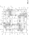
FIG. 2 is a top view of the fixture assembly ofFIG. 1 ; -
FIG. 3 is a top view of the fixture assembly ofFIG. 1 with a plurality of blanks positioned over the electromagnets; -
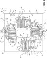
FIG. 4 is a top view of a second example embodiment of a fixture assembly having a second example arrangement of electromagnets; -
FIG. 5 is a perspective view of a pair of electromagnets of a third example embodiment of a fixture assembly; -
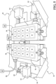
FIG. 6 is a perspective view of the third example embodiment of a fixture assembly; -
FIG. 7 is a perspective view of the fixture assembly ofFIG. 6 with a plurality of blanks positioned over the electromagnets; and -
FIG. 8 is a flow diagram of an example method of using a fixture assembly. - Referring to the Figures, wherein like numerals indicate corresponding parts throughout the several views, a
fixture assembly 20 is provided for laser welding a plurality ofblanks blanks fixture assembly 20 such that edges of theblanks 22 may be welded to one another. It should be appreciated, however, that thesubject fixture assembly 20 could be used to weldblanks blanks - As illustrated in
FIGs. 1-7 , thefixture assembly 20 includes aframe 26. In the example embodiment, theframe 26 is planar and generally square-shaped. Theframe 26 defines a perimeter with fouredges 24, fourcorners 28 and a center. Theframe 26 has anupper surface 30 and alower surface 32 and defines anopening 34 at its center. - A plurality of
electromagnets 36 are positioned on theupper surface 30 of theframe 26. Each of theelectromagnets 36 has a generally cuboid shape with atop face 38 for supporting the blank 22, 23, 25, 27 and for drawing the blank 22 toward thetop face 38. Acontroller 40 is electrically connected to theelectromagnets 36 and is configured to selectively activate theelectromagnets 36 to create a magnetic force for drawing the blank 22 toward theelectromagnet 36. - The plurality of
electromagnets 36 includes fourpairs electromagnets 36, with each pair positioned adjacent to one of theedges 24 of theframe 26. Namely, afirst pair 42, asecond pair 44, athird pair 46 and afourth pair 48 ofelectromagnets 36 are provided. Theelectromagnets 36 of each pair are aligned in spaced and parallel relationship with one another. It should be appreciated that more or fewer pairs ofelectromagnets 36 could be utilized. - A plurality of generally rectangular
shaped intensifiers 50 of a metal material, such as steel, are provided. Eachintensifier 50 overlies thetop face 38 of one of theelectromagnets 36 such that each of theelectromagnets 36 is covered by one of theintensifiers 50. Theintensifiers 50 are each positioned such that, when theelectromagnets 36 are activated, they are drawn toward thetop face 38 of theelectromagnet 36 over the blank 22 to clamp the blank 22, 23, 25, 27 in place in order to intensify the magnetic force provided by theelectromagnet 36, especially forblanks 22 that are of thin gauge metal. - A plurality of supports 54, 56 each interconnect one of the
intensifiers 50 with theupper surface 30 of theframe 26. Thesupports hydraulic lifting cylinder 54 for adjusting the height of theintensifier 50 in a vertical direction that is perpendicular to theframe 26, and a hydraulicrotary cylinder 56 for pivoting theintensifier 50 about a vertical axis A that extends in the vertical direction. It should be appreciated that therotary cylinder 56 allows theintensifier 50 to be pivoted between an overlying position in which it overlies theelectromagnet 36 / blank 22, 23, 25, 27, and a spaced position in which theintensifier 50 does not overly theelectromagnet 36 / blank 22, 23, 25, 27. - As best illustrated in
FIGS. 5-7 , a plurality of hydraulic lines 58 (schematically shown) are connected to thesupports support lifting cylinders 54 and therotary cylinders 56. Thehydraulic lines 58 are also connected to a fluid source 60 (schematically shown) for providing the fluid to thehydraulic lines 58. Thesupports controller 40 for selectively actuating the rotary andlifting cylinders - A plurality of
electromagnet adjusters frame 26 and theelectromagnets 36 for moving theelectromagnets 36 relative to theframe 26 into a desired position. Theelectromagnet adjusters rotary adjuster 62 positioned adjacent to one of theelectromagnets 36 of at least the first andsecond pairs electromagnets 36. Therotary adjusters 62 are configured to rotate the pair ofelectromagnets 36 about an upward axis B that extends parallel to the vertical axis A. Therotary adjusters 62 are connected to thehydraulic lines 58 for receiving hydraulic fluid. Therotary actuator adjusters controller 40 for selectively actuating therotary adjusters 62. Theelectromagnet adjusters adjusters 64 disposed adjacent to each of the pairs ofelectromagnets 36 for pushing the one of theelectromagnets 36 horizontally, i.e., parallel with theframe 26, relative to theother electromagnet 36 of the same pair. The slidingadjusters 64 may also be configured to push both of theelectromagnets 36 at the same time. Each of the slidingadjusters 64 are connected to thehydraulic lines 58 for receiving hydraulic fluid. Furthermore, each of the slidingadjusters 64 are electrically connected to thecontroller 40 for selectively actuating the slidingadjusters 64. - A hydraulic central
vertical adjustment pin 66 is positioned between each of thepairs electromagnets 36 for adjusting a vertical height of the blank 22 in the vertical direction. The central vertical adjustment pins 66 are connected to thehydraulic lines 58 and source ofhydraulic fluid 60 for receiving the hydraulic fluid. The central vertical adjustment pins 66 are also electrically connected to thecontroller 40 for selectively actuating the central vertical adjustment pins 66. - A hydraulic outer
vertical adjustment pin 68 is positioned adjacent to each of thepairs electromagnets 36 for also adjusting a vertical height of the blank 22, 23, 25, 27 in the vertical direction. The outer vertical adjustment pins 68 are connected to thehydraulic lines 58 for receiving hydraulic fluid. The outer vertical adjustment pins 68 are also electrically connected to thecontroller 40 for selectively actuating the outer vertical adjustment pins 68. - A
horizontal adjustment pin 70 is positioned adjacent to each of the outer vertical adjustment pins 68 for pushing anedge 24 of the blank 22, 23, 25, 27 to provide a rough alignment of the blank 22, 23, 25, 27 after it is positioned over theelectromagnets 36. The horizontal adjustment pins 70 are connected to thehydraulic lines 58 for receiving hydraulic fluid. The horizontal adjustment pins 70 are electrically connected to thecontroller 40 for selectively actuating the horizontal adjustment pins 70. - As best shown in
FIGs. 1-3 , a plurality ofplatforms 72 may also be disposed against theframe 26 for supporting theblanks - A method of operating the
subject fixture assembly 20 is presented inFIG. 8 . As illustrated, the method includes 100 arranging thefixture assembly 20 in a start position. Arranging thefixture assembly 20 in the start position includes deactivating allelectromagnets 36, retracting all liftingcylinders 54, extending the vertical adjustment pins 66, 68 and retracting the horizontal adjustment pins 70,rotary cylinders 56 androtary adjusters 62. Retracting therotary cylinders 56 pivots theintensifiers 50 into a pivoted position in which they do not overly theelectromagnet 36, as demonstrated byFIG. 6 . - The method continues with 102 positioning the
blanks electromagnets 36 in a rough position. More particularly, according to the example embodiment best presented inFIGs. 1-3 , a first blank 22 is positioned over one of theelectromagnets 36 of thefirst pair 42 and one of theelectromagnets 36 of thethird pair 46, a second blank 23 is positioned over one of theelectromagnets 36 of thefirst pair 42 and one of theelectromagnets 36 of thefourth pair 48, a third blank 25 is positioned over one of theelectromagnets 36 of thesecond pair 44 and one of theelectromagnets 36 of thefourth pair 48, and a fourth blank 27 is positioned over one of theelectromagnets 36 of thesecond pair 44 and one of theelectromagnets 36 of thethird pair 46. Theblanks - The method continues with 104 pushing the
blanks rotary cylinders 56 such that theintensifiers 50 are positioned over theblanks 22. The method proceeds with 108 activating theelectromagnets 36 of thefirst pair 42 and thesecond pair 44 ofelectromagnets 36. The method continues with 110 releasing the horizontal adjustment pins 70 such that they no longer engage theblanks 22, and 112 lifting theintensifiers 50 with the liftingcylinders 54. - The method proceeds with 114 activating the sliding
adjusters 64 of the first andsecond pairs electromagnets 36 such that any gap between the first andsecond blanks third blanks third pair 46 ofelectromagnets 36 is not activated during such movement, the first andfourth blanks third pair 46 ofelectromagnets 36. The method continues with 116 welding the first andsecond blanks third blanks intensifiers 50 over the first andsecond pair electromagnets 36 are in the lifted position at this time, welding material is able to flow to the gap between the first andsecond blanks third blanks intensifiers 50 with the liftingcylinders 54. - The method continues with 120 activating the
electromagnets 36 of the third andfourth pairs electromagnets 36. The method then proceeds with 122 releasing the slidingadjusters 64 of the first andsecond pairs electromagnets 36. The method then continues with 124 releasing theelectromagnets 36 of the first andsecond pairs electromagnets 36. The method then proceeds with 126 lifting theintensifiers 50 with the liftingcylinder 54. The method continues with 128 activating the slidingadjusters 64 of thethird pair 46 ofelectromagnets 36 such that any gap between the first andfourth blanks 22 is closed. It should be appreciated that because thefirst pair 42 of electromagnets is deactivated at this time, the first blank 22 is able to move relative to thefirst pair 42 ofelectromagnets 42. The method proceeds with 130 welding the first andfourth blanks intensifier 50 over thethird pair 46 ofelectromagnets 36 is in the lifted position, welding material is able to flow to the gap between the first andfourth blanks - The method continues with 132 releasing the sliding
adjusters 64 of thethird pair 46 ofelectromagnets 36. The method proceeds with 134 closing theintensifiers 50 with the liftingcylinders 54. The method continues with 136 releasing theelectromagnets 36 in thethird pair 46. The method proceeds with 138 lifting theintensifiers 50 with the liftingcylinders 54. The method continues with 140 activating the slidingadjusters 64 of thefourth pair 48 ofelectromagnets 36 such that any gap between the second andthird blanks third pair 46 ofelectromagnets 36 is deactivated at this time, the fourth blank 27 is able to move relative to thethird pair 46 ofelectromagnets 36. The method proceeds with 142 welding the second andthird blanks intensifier 50 over thethird pair 46 ofelectromagnets 36 is in the lifted position, welding material is able to flow to the gap between the second andthird blanks - The method continues with 144 releasing the sliding
adjusters 64 of thefourth pair 48 ofelectromagnets 36. The method proceeds with 146 deactivating thefourth electromagnet 36. The method continues with 148 lifting theintensifiers 50 with the liftingcylinders 54 and rotating theintensifiers 50 into a pivoted position such that they do not overly theelectromagnet 36. The method proceeds with 150 activating all of the slidingadjusters 64 such that theelectromagnets 36 are moved back to their original positions. Finally the method continues with 152 removing the coupledblanks 22 from thefixture assembly 20. - It should be appreciated that the
electromagnets 36 and various supports, adjusters, actuators, intensifiers, may be activated in different manners and in different orders in order to provide a desired alignment for differently shapedblanks 22 to be welded to one another. For example, therotary adjusters 62 may rotate theelectromagnets 36 at any point in the process to position theblanks - Obviously, many modifications and variations of the present invention are possible in light of the above teachings and may be practiced otherwise than as specifically described while within the scope of the appended claims. These antecedent recitations should be interpreted to cover any combination in which the inventive novelty exercises its utility. The use of the word "said" in the apparatus claims refers to an antecedent that is a positive recitation meant to be included in the coverage of the claims whereas the word "the" precedes a word not meant to be included in the coverage of the claims.
-
-
Embodiment 1. A fixture assembly for supporting a plurality of blanks during a welding operation, said fixture assembly including:- a frame;
- a plurality of electromagnets positioned on said frame for supporting the blanks and for drawing the blanks toward said electromagnets to inhibit relative movement between the blanks and said electromagnets upon being activated;
- a plurality of intensifiers moveably connected to said frame for selectively overlying said electromagnets for being drawn toward said electromagnets over the blank to clamp the blank in place and to intensify a magnetic force provided by said electromagnets when said electromagnets are activated;
- at least one adjusting pin connected to said frame and moveable relative to said frame for adjusting a position of the blanks relative to said electromagnets prior to activating the electromagnets; and
- a plurality of electromagnet adjusters each coupled to said frame and at least one of said electromagnets for moving said at least one of said electromagnets relative to said frame after said electromagnets have been activated for closing any gaps between said blanks.
-
Embodiment 2. The fixture assembly as set forth inEmbodiment 1 further including a plurality of supports each moveably connecting one of said intensifiers and said frame. -
Embodiment 3. The fixture assembly as set forth inEmbodiment 2 wherein said plurality of supports includes at least one lifting cylinder moveable in a vertical direction being generally perpendicularly to said frame for adjusting at least one of said intensifiers in the vertical direction. -
Embodiment 4. The fixture assembly as set forth inEmbodiment 2 wherein said plurality of supports includes at least one rotary cylinder pivotable about a vertical axis extending generally perpendicularly to said frame for pivoting at least one of said intensifiers about said vertical axis between an overlying position in which said intensifier overlies said electromagnet and a spaced position in which said intensifier does not overly said electromagnet. -
Embodiment 5. The fixture assembly as set forth inEmbodiment 1 wherein said plurality of electromagnet adjusters includes at least one rotary adjuster rotatable about an upward axis that extends generally perpendicularly to said frame. - Embodiment 6. The fixture assembly as set forth in
Embodiment 1 wherein said frame is generally disposed along a plane, and said plurality of electromagnet adjusters includes at least one sliding adjuster moveable along said plane of said frame for pushing said electromagnets along said plane. - Embodiment 7. The fixture assembly as set forth in
Embodiment 1 wherein said at least one adjustment pin includes at least one vertical adjustment pin moveable in a vertical direction being generally perpendicular to said frame for adjusting a vertical height of the blank in said vertical direction. - Embodiment 8. The fixture assembly as set forth in Embodiment 7 wherein said at least one vertical adjustment pin includes at least one central vertical adjustment pin positioned between a pair of said electromagnets.
- Embodiment 9. The fixture assembly as set forth in Embodiment 7 wherein said at least one vertical adjustment pin includes at least one outer vertical adjustment pin positioned adjacent to a pair of said electromagnets.
- Embodiment 10. The fixture assembly as set forth in
Embodiment 1 wherein said at least one adjustment pin includes at least one horizontal adjustment pin positioned moveable horizontally parallel to said frame for moving the blank horizontally. - Embodiment 11. The fixture assembly as set forth in
Embodiment 1 wherein said plurality of electromagnets includes a plurality of pairs of electromagnets with said electromagnets of each pair aligned in spaced and parallel relationship with one another. - Embodiment 12. The fixture assembly as set forth in Embodiment 11 wherein said frame is generally square shaped and extends along a plane, wherein said frame defines four edges and four corners, and wherein said plurality of pairs of electromagnets includes four pairs of electromagnets with each pair positioned adjacent to one of said edges of said frame.
- Embodiment 13. The fixture assembly as set forth in
Embodiment 1 further including a plurality of hydraulic lines coupled with said electromagnet adjusters and said at least one adjusting pin for actuating said electromagnet adjusters and said at least one adjusting pin. - Embodiment 14. A method for positioning a plurality of blanks on a frame for a welding operation, said method including:
- positioning at least two blanks on top of at least two electromagnets being positioned on top of the frame;
- pushing the at least two blanks relative to the frame into a preliminary position with at least one adjusting pin;
- positioning a plurality of intensifiers of a magnetic material over each of the electromagnets and blanks;
- activating the electromagnets to draw the blanks and intensifiers toward the electromagnets to inhibit relative movement between the blanks and the electromagnets; and
- moving at least one of the electromagnets from the preliminary position with at least one electromagnet adjuster to eliminate any gap between the pair of blanks such that the blanks may be welded to one another.
Claims (15)
- A fixture assembly for supporting a plurality of blanks during a welding operation, said fixture assembly including:a frame having an upper surface extending along a plane;a plurality of electromagnets positioned on the upper surface of the frame, each of the electromagnets having a top face extending along a plane being parallel to the plane of the frame for supporting one of the blanks and for drawing the blank toward the top face to inhibit relative movement between the blank and the electromagnet upon being activated;at least one adjusting pin connected to the frame and moveable relative to the frame for adjusting a position of at least one of the blanks relative to the electromagnets prior to activating the electromagnets; anda plurality of electromagnet adjusters coupled to the frame and configured to move the at least one of the electromagnets relative to the frame after the electromagnets have been activated for closing gaps between the blanks, wherein at least one of the electromagnet adjusters is configured to move the at least one of the electromagnets in a horizontal direction being parallel with the plane of the frame, and wherein at least one of the electromagnet adjusters is configured to rotate the at least one of the electromagnets.
- The fixture assembly as set forth in claim 1, wherein the plurality of electromagnet adjuster includes at least one sliding adjuster configured to push the at least one electromagnet in the horizontal direction, and at least one rotary adjuster configured to rotate the at least one of the electromagnet.
- The fixture assembly as set forth in claim 1, further including a plurality of intensifiers moveably connected to the frame each for selectively overlying one of the electromagnets for being drawn toward the electromagnet over the blank to clamp the blank in place and to intensify a magnetic force provided by the electromagnet when the electromagnets are activated.
- The fixture assembly as set forth in claim 3, further including a plurality of supports each moveably connecting one of the intensifiers and the frame.
- The fixture assembly as set forth in claim 4 wherein the plurality of supports includes at least one lifting cylinder moveable in a vertical direction being perpendicular to the frame, and wherein the lifting cylinder is configured to move at least one of the intensifiers in the vertical direction.
- The fixture assembly as set forth in claim 3 wherein the intensifiers are each pivotable about a vertical axis being perpendicular to the plane of the frame between an overlying position in which the intensifier overlies the electromagnet in a vertical direction of the vertical axis and a spaced position in which the intensifier does not overlie the electromagnet in the vertical direction for selectively clamping the blank to the electromagnet.
- The fixture assembly as set forth in claim 1 wherein the at least one adjusting pin includes at least one vertical adjustment pin moveable in a vertical direction being perpendicular to the plane of the frame and configured to adjust a vertical height of the blanks in the vertical direction.
- The fixture assembly as set forth in claim 7 wherein the at least one vertical adjustment pin includes at least one central vertical adjustment pin positioned in a region between a pair of the electromagnets.
- The fixture assembly as set forth in claim 8 wherein the at least one vertical adjustment pin includes at least one outer vertical adjustment pin positioned adjacent to a pair of the electromagnets outside of the region between the pair of the electromagnets.
- The fixture assembly as set forth in claim 1 wherein the at least one adjusting pin includes at least one horizontal adjustment pin moveable in the horizontal direction and configured to move the blanks in the horizontal direction.
- The fixture assembly as set forth in claim 1 wherein the plurality of electromagnets includes a plurality of pairs of electromagnets with the electromagnets of each pair aligned in spaced and parallel relationship with one another.
- The fixture assembly as set forth in claim 11 wherein the frame is square shaped, wherein the frame defines four edges and four corners, and wherein the plurality of pairs of electromagnets includes four pairs of electromagnets with each of the pairs of electromagnets positioned adjacent to one of the edges of the frame.
- A method for positioning a plurality of blanks for a welding operation, the method including:providing a frame having an upper surface extending along a plane;positioning a plurality of electromagnets on the upper surface of the frame, wherein each of the electromagnets has a top surface extending along a plane being parallel to the plane of the frame;positioning at least two blanks on top of the top surfaces of at least two of the electromagnets;pushing the at least two blanks relative to the frame into a preliminary position with at least one adjusting pin;activating at least one of the electromagnets to draw at least one of the blanks toward the at least one of the electromagnets to inhibit relative movement between the at least one of the blanks and the at least one of the electromagnets; andmoving at least one of the electromagnets in a horizontal direction being parallel with the plane of the frame with at least one electromagnet adjuster, and rotating at least one of the electromagnets with the at least one electromagnet adjustor to eliminate gaps between the plurality of blanks such that the blanks may be welded to one another.
- The method as set forth in claim 13, further including positioning a plurality of intensifiers of a magnetic material over each of the electromagnets and blanks, and activating the at least one of the intensifiers to further draw the at least one of the blanks toward the at least one of the electromagnets to inhibit relative movement between the at least one of the blanks and the at least one of the electromagnets.
- The method as set forth in claim 13, wherein the at least one electromagnet adjuster includes at least one sliding adjuster configured to push the at least one electromagnet in the horizontal direction and at least one rotary adjuster configured to rotate the at least one of the electromagnets.
Applications Claiming Priority (3)
| Application Number | Priority Date | Filing Date | Title |
|---|---|---|---|
| US201762591950P | 2017-11-29 | 2017-11-29 | |
| EP18884360.1A EP3717173B1 (en) | 2017-11-29 | 2018-11-29 | Fixture assembly and method for welding operations |
| PCT/CA2018/000229 WO2019104412A1 (en) | 2017-11-29 | 2018-11-29 | Fixture assembly for welding operations |
Related Parent Applications (1)
| Application Number | Title | Priority Date | Filing Date |
|---|---|---|---|
| EP18884360.1A Division EP3717173B1 (en) | 2017-11-29 | 2018-11-29 | Fixture assembly and method for welding operations |
Publications (2)
| Publication Number | Publication Date |
|---|---|
| EP4420821A2 true EP4420821A2 (en) | 2024-08-28 |
| EP4420821A3 EP4420821A3 (en) | 2025-01-01 |
Family
ID=66663751
Family Applications (2)
| Application Number | Title | Priority Date | Filing Date |
|---|---|---|---|
| EP24179898.2A Pending EP4420821A3 (en) | 2017-11-29 | 2018-11-29 | Fixture assembly and method for welding operations |
| EP18884360.1A Active EP3717173B1 (en) | 2017-11-29 | 2018-11-29 | Fixture assembly and method for welding operations |
Family Applications After (1)
| Application Number | Title | Priority Date | Filing Date |
|---|---|---|---|
| EP18884360.1A Active EP3717173B1 (en) | 2017-11-29 | 2018-11-29 | Fixture assembly and method for welding operations |
Country Status (7)
| Country | Link |
|---|---|
| US (1) | US11607755B2 (en) |
| EP (2) | EP4420821A3 (en) |
| CN (1) | CN111417490B (en) |
| CA (1) | CA3079095A1 (en) |
| ES (1) | ES2981378T3 (en) |
| HU (1) | HUE068004T2 (en) |
| WO (1) | WO2019104412A1 (en) |
Families Citing this family (12)
| Publication number | Priority date | Publication date | Assignee | Title |
|---|---|---|---|---|
| CN117157167A (en) | 2021-04-09 | 2023-12-01 | 麦格纳国际公司 | System for welding a plurality of blanks into a component |
| JP7541121B2 (en) * | 2022-01-14 | 2024-08-27 | 日銘電脳配件(上海)有限公司 | Welding jig and clamping method |
| CN114713983B (en) * | 2022-04-06 | 2023-05-23 | 无锡新松机器人自动化有限公司 | Automatic assembling clamp for automobile door ring laser tailor-welded steel plate and operation method |
| KR102706414B1 (en) * | 2022-06-24 | 2024-09-13 | 한국기계연구원 | Work holder having electro-permanent magnetic type for curved surface and work holder assembly having the same |
| CN115319286B (en) * | 2022-08-23 | 2023-05-23 | 珠海市歌雅门窗有限公司 | Aluminum skylight alloy frame destressing welding device |
| CN115592333B (en) * | 2022-11-23 | 2025-08-26 | 洛阳市锐创电气设备有限公司 | Adjustable cabinet frame welding fixture |
| CN116000446A (en) * | 2023-01-31 | 2023-04-25 | 广州优尼冲压有限公司 | Positioning and adjusting mechanism for laser welding of automobile parts |
| CN116900571A (en) * | 2023-08-31 | 2023-10-20 | 博众精工科技股份有限公司 | Carrier for welding and assembling |
| CN117773444B (en) * | 2023-11-24 | 2024-06-21 | 南京海高德新技术有限公司 | High-efficient welding set of coupling mount pad |
| CN118832335B (en) * | 2024-09-23 | 2024-12-03 | 贵州省公路工程集团有限公司 | Welding method of beret sheet |
| CN119973512B (en) * | 2025-03-13 | 2025-08-29 | 江苏艾珀耐尔节能科技有限公司 | Welding device for processing lighting and smoke exhaust skylights |
| CN120133873B (en) * | 2025-04-03 | 2025-09-30 | 东莞市简智电子有限公司 | Bimetal assembly and fixed plate forming welding equipment of temperature controller |
Family Cites Families (21)
| Publication number | Priority date | Publication date | Assignee | Title |
|---|---|---|---|---|
| US5023427A (en) * | 1990-04-12 | 1991-06-11 | Armco Steel Company, L.P. | Method and apparatus for automatically aligning proximal edges of sheets to be butt welded |
| DE4227848B4 (en) * | 1991-11-28 | 2009-05-07 | Robert Bosch Gmbh | Component carrier and method for holding a formed of a ferromagnetic material component |
| US5630269A (en) * | 1995-06-19 | 1997-05-20 | General Motors Corporation | Method for fixturing abutted sheet metal parts for welding |
| JP3586021B2 (en) * | 1995-11-28 | 2004-11-10 | 有限会社木村鉄工所 | Positioning jig for welding steel segments and welding equipment |
| CA2167111A1 (en) * | 1996-01-12 | 1997-07-13 | Bob Bishop | Method and apparatus for butt welding together sheet blanks |
| FR2749528B1 (en) * | 1996-06-07 | 1998-09-04 | Renault Automation | DEVICE FOR CLAMPING A SHEET PIECE AND DEVICE FOR FIXING TWO SHEETS APPLIED |
| DE19705553C1 (en) * | 1997-02-14 | 1998-04-02 | Daimler Benz Aerospace Airbus | Electromagnetic clamping system for fixing and clamping large parts esp. in aeroplane mfg. |
| US6031199A (en) * | 1997-10-28 | 2000-02-29 | Worthington Machine Technology | Combination laser cutting and blank welding apparatus and method |
| EP1874504B1 (en) * | 2005-04-25 | 2012-09-12 | Uttam Sarda | Magnetic and mechanical work holding apparatus with monolithic working face |
| US20090283946A1 (en) * | 2008-05-19 | 2009-11-19 | Gm Global Technology Operations, Inc. | Single-sided magnetic fixturing systems |
| WO2010071109A1 (en) * | 2008-12-16 | 2010-06-24 | 株式会社Ihi | Wewlding apparatus and method of welding using the apparatus |
| CN101491868A (en) * | 2009-03-03 | 2009-07-29 | 江苏圣丰建设有限公司 | Frame component of metal steel structure and anti-deforming welding method |
| US8912872B2 (en) * | 2012-04-30 | 2014-12-16 | The Boeing Company | Clamp assembly including permanent magnets and coils for selectively magnetizing and demagnetizing the magnets |
| US9555522B2 (en) * | 2013-01-25 | 2017-01-31 | Totota Motor Europe Nv/Sa | Systems and methods for welding |
| WO2015027346A1 (en) * | 2013-08-27 | 2015-03-05 | Andritz Soutec Ag | Method for continuously conveying and butt-welding sheet metal parts, and use of said method |
| EP3206831B1 (en) * | 2014-10-15 | 2020-05-06 | Autotech Engineering S.L. | Welding of steel blanks |
| US9969077B2 (en) * | 2014-11-11 | 2018-05-15 | Lincoln Global, Inc. | Workpiece positioning apparatus, and method of using same |
| US10821548B2 (en) * | 2015-03-20 | 2020-11-03 | Honda Motor Co., Ltd. | Plate-material abutting device |
| CN105234616B (en) * | 2015-11-16 | 2017-03-29 | 江苏凯宫机械股份有限公司 | The hydraulically operated fixture of welding robot workstation |
| KR101750376B1 (en) * | 2016-12-16 | 2017-06-23 | 화천기공 주식회사 | Electromagnet chuck mounting structure |
| CN106817666B (en) * | 2017-03-18 | 2019-08-27 | 歌尔股份有限公司 | The welding tooling and welding method of motor vibrator |
-
2018
- 2018-11-29 ES ES18884360T patent/ES2981378T3/en active Active
- 2018-11-29 CN CN201880076793.1A patent/CN111417490B/en active Active
- 2018-11-29 CA CA3079095A patent/CA3079095A1/en active Pending
- 2018-11-29 EP EP24179898.2A patent/EP4420821A3/en active Pending
- 2018-11-29 US US16/760,619 patent/US11607755B2/en active Active
- 2018-11-29 EP EP18884360.1A patent/EP3717173B1/en active Active
- 2018-11-29 WO PCT/CA2018/000229 patent/WO2019104412A1/en not_active Ceased
- 2018-11-29 HU HUE18884360A patent/HUE068004T2/en unknown
Also Published As
| Publication number | Publication date |
|---|---|
| WO2019104412A1 (en) | 2019-06-06 |
| CN111417490B (en) | 2023-02-28 |
| US11607755B2 (en) | 2023-03-21 |
| CA3079095A1 (en) | 2019-06-06 |
| EP3717173A4 (en) | 2021-09-22 |
| US20210178529A1 (en) | 2021-06-17 |
| ES2981378T3 (en) | 2024-10-08 |
| EP3717173A1 (en) | 2020-10-07 |
| EP3717173B1 (en) | 2024-06-05 |
| HUE068004T2 (en) | 2024-12-28 |
| CN111417490A (en) | 2020-07-14 |
| EP4420821A3 (en) | 2025-01-01 |
Similar Documents
| Publication | Publication Date | Title |
|---|---|---|
| US11607755B2 (en) | Fixture assembly for welding operations | |
| US12179293B2 (en) | Fixture assembly for supporting blanks during shearing and welding operations | |
| US20060191979A1 (en) | Device for tightly fastening at least two members | |
| KR100933638B1 (en) | Electromagnet jig device for laser welding | |
| EP4403296A2 (en) | System for welding multiple blanks into a component | |
| KR101648977B1 (en) | Jig device for floor frame assembling of special vehicle loading box | |
| CN111263677B (en) | Welding assembly, welding device and method for welding | |
| JP2011167703A (en) | Welding support stand for joint | |
| KR101857613B1 (en) | Frame making jig device for elevator weight | |
| US20240116143A1 (en) | Fastener welding apparatus | |
| CN210451548U (en) | A fixture for welding of switchgear or vacuum circuit breaker cabinet | |
| CN116900586A (en) | Edge holder for welding equipment and welding equipment including the edge holder | |
| US6988390B2 (en) | Method and installation for making a workpiece comprising at least a tubular section | |
| CN217890015U (en) | Crane beam body returns shape board welding jig | |
| CN116673676B (en) | Limiting device for sheet metal part welding processing | |
| CN109865972B (en) | Bending workpiece welding tooling | |
| CN211661357U (en) | A laser welding fixture | |
| KR20140106144A (en) | Apparatus for Preventing Welding Distortion | |
| CN108637116B (en) | Positioning device | |
| KR20160139178A (en) | Welding structure of vacuum valve and method and apparatus thereof | |
| CN119457929A (en) | Fixture | |
| CN121666288A (en) | Clamping device for workpieces | |
| JPH11771A (en) | Joining equipment |
Legal Events
| Date | Code | Title | Description |
|---|---|---|---|
| PUAI | Public reference made under article 153(3) epc to a published international application that has entered the european phase |
Free format text: ORIGINAL CODE: 0009012 |
|
| STAA | Information on the status of an ep patent application or granted ep patent |
Free format text: STATUS: THE APPLICATION HAS BEEN PUBLISHED |
|
| AC | Divisional application: reference to earlier application |
Ref document number: 3717173 Country of ref document: EP Kind code of ref document: P |
|
| AK | Designated contracting states |
Kind code of ref document: A2 Designated state(s): AL AT BE BG CH CY CZ DE DK EE ES FI FR GB GR HR HU IE IS IT LI LT LU LV MC MK MT NL NO PL PT RO RS SE SI SK SM TR |
|
| REG | Reference to a national code |
Ref country code: DE Ref legal event code: R079 Free format text: PREVIOUS MAIN CLASS: B23K0037047000 Ipc: B23K0037040000 |
|
| PUAL | Search report despatched |
Free format text: ORIGINAL CODE: 0009013 |
|
| RIC1 | Information provided on ipc code assigned before grant |
Ipc: B23K 101/18 20060101ALN20241119BHEP Ipc: B23K 26/26 20140101ALI20241119BHEP Ipc: B23K 37/047 20060101ALI20241119BHEP Ipc: B23K 26/242 20140101ALI20241119BHEP Ipc: B23Q 3/154 20060101ALI20241119BHEP Ipc: B23K 26/70 20140101ALI20241119BHEP Ipc: B23K 37/04 20060101AFI20241119BHEP |
|
| AK | Designated contracting states |
Kind code of ref document: A3 Designated state(s): AL AT BE BG CH CY CZ DE DK EE ES FI FR GB GR HR HU IE IS IT LI LT LU LV MC MK MT NL NO PL PT RO RS SE SI SK SM TR |
|
| RIC1 | Information provided on ipc code assigned before grant |
Ipc: B23K 101/18 20060101ALN20241122BHEP Ipc: B23K 26/26 20140101ALI20241122BHEP Ipc: B23K 37/047 20060101ALI20241122BHEP Ipc: B23K 26/242 20140101ALI20241122BHEP Ipc: B23Q 3/154 20060101ALI20241122BHEP Ipc: B23K 26/70 20140101ALI20241122BHEP Ipc: B23K 37/04 20060101AFI20241122BHEP |
|
| STAA | Information on the status of an ep patent application or granted ep patent |
Free format text: STATUS: REQUEST FOR EXAMINATION WAS MADE |
|
| 17P | Request for examination filed |
Effective date: 20250701 |
|
| STAA | Information on the status of an ep patent application or granted ep patent |
Free format text: STATUS: EXAMINATION IS IN PROGRESS |
|
| 17Q | First examination report despatched |
Effective date: 20251015 |