EP4419862B1 - Rückstoss-system - Google Patents
Rückstoss-system Download PDFInfo
- Publication number
- EP4419862B1 EP4419862B1 EP22793206.8A EP22793206A EP4419862B1 EP 4419862 B1 EP4419862 B1 EP 4419862B1 EP 22793206 A EP22793206 A EP 22793206A EP 4419862 B1 EP4419862 B1 EP 4419862B1
- Authority
- EP
- European Patent Office
- Prior art keywords
- wheel
- carriage
- field gun
- gun according
- recoil
- Prior art date
- Legal status (The legal status is an assumption and is not a legal conclusion. Google has not performed a legal analysis and makes no representation as to the accuracy of the status listed.)
- Active
Links
Images

Classifications
-
- F—MECHANICAL ENGINEERING; LIGHTING; HEATING; WEAPONS; BLASTING
- F41—WEAPONS
- F41A—FUNCTIONAL FEATURES OR DETAILS COMMON TO BOTH SMALLARMS AND ORDNANCE, e.g. CANNONS; MOUNTINGS FOR SMALLARMS OR ORDNANCE
- F41A23/00—Gun mountings, e.g. on vehicles; Disposition of guns on vehicles
- F41A23/34—Gun mountings, e.g. on vehicles; Disposition of guns on vehicles on wheeled or endless-track vehicles
-
- F—MECHANICAL ENGINEERING; LIGHTING; HEATING; WEAPONS; BLASTING
- F41—WEAPONS
- F41A—FUNCTIONAL FEATURES OR DETAILS COMMON TO BOTH SMALLARMS AND ORDNANCE, e.g. CANNONS; MOUNTINGS FOR SMALLARMS OR ORDNANCE
- F41A23/00—Gun mountings, e.g. on vehicles; Disposition of guns on vehicles
- F41A23/28—Wheeled-gun mountings; Endless-track gun mountings
-
- F—MECHANICAL ENGINEERING; LIGHTING; HEATING; WEAPONS; BLASTING
- F41—WEAPONS
- F41A—FUNCTIONAL FEATURES OR DETAILS COMMON TO BOTH SMALLARMS AND ORDNANCE, e.g. CANNONS; MOUNTINGS FOR SMALLARMS OR ORDNANCE
- F41A25/00—Gun mountings permitting recoil or return to battery, e.g. gun cradles; Barrel buffers or brakes
- F41A25/16—Hybrid systems
Definitions
- the present invention relates to a field gun with wheel carriage, specifically to a wheel carriage with regenerative braking system as part of the recoil system.
- the ordnance is aimed (i.e. has traverse or elevation varied) using a carriage and soleplate arrangement.
- the soleplate is a plate-like platform that sits on the ground so as to bear the weight of the Gun and oppose any forward tipping moments; forward tipping moments are greatest during counter recoil.
- the soleplate is provided with a carriage mounted on top.
- the soleplate and carriage are connected by a swivel joint, thus the carriage can swivel in the plane of the ground (e.g. when the ground is horizontal, the carriage will swivel in a horizontal plane) so as to vary the ordnance traverse.
- the carriage is connected to the ordnance by way of trunnions that extend laterally from the cradle thus the ordnance can rotate about the trunnion/saddle connection to vary the elevation.
- field guns are desired to be lightweight. Lightweight field guns are desirable because they can be transported by a wider range of vehicles and because a greater number of them may be carried by a given transport vehicle. Thus field guns can be deployed faster than heavier alternatives.
- US 6457396 B1 describes a self propelled gun comprising a vehicle possessing a source of primary power and a gun assembly movably attached to the vehicle.
- US 9481414 B1 describes a spherical tractor operating mobile platform (STOMP) for internally propelling and steering along an external surface
- STOMP spherical tractor operating mobile platform
- a field gun comprising:
- the regenerative device may be operably linked with the rechargeable electric storage device and the at least one wheel for dissipating the recoil of the field gun by decelerating the wheel, and additionally generating an electrical current.
- a processor connected to the brake control and to the rechargeable electric storage device such that in response to a first movement of the carriage, caused by the recoil from firing the gun, the processor causes the regenerative device to decelerate the wheel, and dissipate the energy of the recoil.
- the first movement being a movement caused by the recoil force from the firing of the projectile from the gun barrel.
- the carriage may be towed or self-propelled vehicle, preferably the carriage is a self-propelled vehicle.
- the carriage may be electrically powered or combustion engine powered. In a highly preferred arrangement the carriage is an electric powered vehicle or hybrid-electric powered vehicle.
- the electric storage may be a rechargeable battery and/or may comprise a fast charging capacitor.
- the capacitor may be able to accept a generated charge at a much faster rate than a rechargeable battery.
- the electric vehicle may comprise an electric motor operatively connected to a driving wheel and/or the at least one wheel to drive the driving wheel and/or at least one wheel; and a motor controller configured to connect the rechargeable electric storage device to the electric motor to power the motor.
- the electrical storage system may also provide electrical power to operate the electronic components on the gun system, such as, for example the fire control system, aiming, communications, loading ammunition, etc.
- the regenerative braking system may be used in combination with an internal combustion engine powered vehicle, wherein the electrical storage device is used to provide electrical power either as supplementary driving power and/or to operate the electronic components on the gun system, such as, for example the fire control system, aiming, communications, loading ammunition, etc.
- the vehicle may preferably have more than one wheel, preferably two or three; there may be at least four wheels, with at least one wheel comprising said regenerative braking system.
- Many military vehicles have 6, 8 or more wheels, with any one or all being driven wheels or at least one wheels.
- the vehicle may comprise wheels for steering and/or driving.
- the at least one wheel may also be a steering, driving or drop axle wheel(non-driving wheel).
- the at least one wheel may also be a drive wheel, road wheel or idler wheel (non-driving wheel) of a tracked vehicle.
- the regenerative braking system may preferably be applied to pairs of wheels, to allow a uniform braking force to be applied. It is desirable that braking is performed in a substantially straight line, to avoid the carriage and gun from moving sideways, which may cause tipping, (ie deceleration may preferably be only in the direction of the main axis which is defined as the axis of the gun and wheeled carriage). Steering may be locked during the firing of the gun, to confine movement in only the main axis, to mitigate tipping of the gun.
- the regenerative braking system may comprise an anti-lock braking system (ABS).
- ABS anti-lock braking system
- the regenerative braking, effect may be reduced or immediately removed when antilock braking is activated.
- the ABS ensures that the recoil force is reduced and does not cause the carriage to enter into a skid, which may be difficult to control should the recoil force cause any movement no along the main axis.
- the ABS may be an algorithm on the processer of the regenerative braking system or a separate ABS friction braking system.
- the elevating mass may comprise a piston recoil system and a piston recuperator system, applied to the barrel in a conventional manner.
- the regenerative braking system may be used as a primary means or secondary means of retarding ie absorbing the recoil force.
- the degree of resistance of the piston recoil system and regenerative braking system are controlled by the processor to ensure that the gun system has the recoil energy safely dissipated and to maximise the generation of electricity.
- the regenerative braking system may be applied progressively to increase the amount of braking force during the recoil force.
- the recoil force can be controlled by changing the buffer porting along the length of the stroke. This energy may be arranged to transfer a portion of the stored hydro-pneumatic system energy to the regen system.
- a hydro-pneumatic system comprising a valve arrangement, or means of variably controlling the port size/position adjustment in the hydro-pneumatic system may also allow the ratio of recoil force between the hydro-pneumatic system and the regenerative systems to be adjusted with respect to time, and further depending on the mass of the charge used to propel the ammunition.
- the response to the first movement of the vehicle may be any detected by a motion detector, either mounted on the vehicle, such as the wheel, or part of the regenerative braking system.
- the movement such as velocity and acceleration may be monitored to determine the amount of recoil force originating from the firing of the gun, and thereby to determine the counter opposing force required by the regenerative braking system and the piston recoil system.
- the vehicle comprises a regenerative braking system having at least one wheel, preferably at least a pair of front wheels and pair of rear wheels, wherein at least one set of wheels includes a drive wheel, an actuating device, a regenerative braking control circuit, and power electronics.
- the regenerative braking control circuit may include a transducer, such as for example a potentiometer or digital encoder, a process sensor, and the processor.
- the power electronics circuit includes a rechargeable electric power source, an electric motor, and a motor controller.
- the actuating device may be coupled to the transducer.
- the transducer and process sensors signal the processor which produces an output signal to the motor controller for regulating a regenerative braking torque to the at least one wheel.
- the braking system applies a regenerative braking torque to the at least one wheel when the transducer signals a regenerative braking command, and the process sensors receive a signal from the motion detector via the at least one wheel, that the velocity greater than zero.
- the braking torque increases with an increase in the transducer signal as detected by the motion detector, and the processor adjusts the braking torque.
- the motor acts as a generator supplying current to the battery which loads down the generator, thereby causing a braking action.
- the gearbox may increase the speed of the regenerative braking system, such as to increase the flux cutting in the regenerative system, to improve the braking force of the regenerative system.
- Wheeled vehicles typically comprise suspension systems, to allow the vehicle to traverse over uneven ground.
- the suspension systems may be passive or active, and may dissipate part of the recoil force.
- the carriage assembly may also comprise conventional passive recoil systems, such as physical components which are pushed into the ground to allow recoils forces to be directed into the ground; the carriage may further comprise
- the front stabilisers may extend to rest on the ground at a foremost ground contact point and the rear trails extend to rest on the ground at a backmost ground contact point such that the foremost ground contact point is situated below the barrel and substantially forwards of the field gun's centre of gravity so as to be able to oppose the tipping moment induced during counter-recoil.
- the rear trails may comprise a trail leg, a trail arm pivotally connected to said trail leg, a spade and a damper, wherein said damper is located between the trail leg and trail arm.
- the trail leg is required to maintain the rearward position of the spades relative to the elevating mass in order to achieve stability, particularly when firing at low elevation.
- a damper may be fitted into the trail leg and when deployed in the firing position the damper piston seats against the underside of the trail arm. The damper provides resilience between the leg and the arm and allows the spade to rotate about the trail leg/arm hinge to self-dig into the ground during firing.
- front stabilisers and rear trails are therefore at the periphery of the field gun's ground base and so they can oppose the forces that the howitzer experiences during firing so that the field gun does not topple
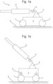
- a gun system 1 with a body 4, wheels 7.
- the body 4 comprising a trunnion 3 which provides a bearing for the gun barrel 8 to be mounted on.
- the gun barrel 8, further comprising a recoil/recuperator system 2, to absorb the energy.
- the wheels 7 being generally connected to the body 4, by means of vehicle suspension 9.
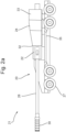
- Figure 2a is in a horizontal firing position 21, and Figure 2b provides a high angle elevation firing position 31.
- the field gun 20 comprising an elevating mass 28 with a barrel/ordnance 32 for firing a projectile.
- the barrel axis is the main axis of the vehicle and the gun barrel 32.
- the muzzle and muzzle brake 30 is located at the nominal front end of the field gun, with a breech 33 assembly at the rear end of the barrel.
- the cradle 34 holds the ordnance at a traverse and an elevation.
- the wheeled carriage 35 comprising at least one wheel 27.
- the wheels may be driven by a combustion engine electrical motors, or hybrid means (not shown). The wheels are linked to he carriage 35 by suspension 29.
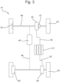
- a wheeled carriage 41 comprising a rechargeable electric storage device 51; and a regenerative braking system 42.
- the regenerative a system comprising a brake control (not shown) configured for applying a braking force to the wheel 43 in response to movement of the carriage 41 by a recoil force from the firing of the projectile from the gun barrel.
- the regenerative braking system 42 is located on an axle 48.
- a wheel hub mounted regenerative braking system 62 is located on each wheel. 43.
- the regenerative braking system 42, 62 may further comprise a gearbox 47 or variable transmission means to speed up the flux cutting in the regenerative braking system, so as to allow slow carriage velocities to still provide an effective regenerative braking force.
- the wheels 43 may also further comprise friction brakes 54, to provide greater stopping forces.
- the carriage 41 may be powered by a driven train 45, such as, an internal combustion engine, electric motor or hybrid, wherein the drive may be transferred by drive shafts 46.
- the carriage may be powered by electrical motors 44 located either proximate to or located within(hub motor) the wheels 43.
- the electrical power 52 may be provided by the rechargeable battery 51.
- the rechargeable battery 51 may be recharged by the action of the regenerative braking system 42, 62 which flows electricity 50 into the rechargeable battery 51.
Landscapes
- Engineering & Computer Science (AREA)
- General Engineering & Computer Science (AREA)
- Electric Propulsion And Braking For Vehicles (AREA)
- Rehabilitation Tools (AREA)
- Stopping Of Electric Motors (AREA)
Claims (9)
- Feldgeschütz (20), umfassend:i) eine Hebemasse (28), umfassend:eine Geschütz (32) zum Abfeuern eines Projektils, das Geschütz umfassend einen Lauf, der eine Laufachse definiert und eine Mündung (30) zu dem vorderen Ende des Feldgeschützes hin und eine Verschlussanordnung (33) an dem hinteren Ende des Laufs aufweist; undein Gestell (34) zum Halten des Geschützes in einer Traverse und einer Erhebung; undmindestens ein kooperatives Eingriffsmittel zum Koppeln des Gestells mit einem mit Rädern versehenen Transportmittel (41),ii) das mit Rädern versehene Transportmittel umfassendmindestens ein Rad (43);dadurch gekennzeichnet, dass das mit Rädern versehene Transportmittel ferner umfasst:eine wiederaufladbare elektrische Speichervorrichtung (51); undein regeneratives Bremssystem (42), umfassend:eine Bremssteuerung, die zum Ausüben einer Bremskraft auf das mindestens eine Rad als Reaktion auf eine Bewegung des mit Rädern versehenen Transportmittels aufgrund durch eine Rückstoßkraft von dem Abfeuern des Projektils aus dem Gewehrlauf konfiguriert ist.
- Feldgeschütz nach Anspruch 1, wobei die Regenerationsvorrichtung mit der wiederaufladbaren elektrischen Speichervorrichtung und dem mindestens einen Rad wirkgekoppelt ist, zum Erzeugen von elektrischem Strom durch Abbremsen des Rads und Ableiten des Rückstoßes des Feldgeschütz.
- Feldgeschütz nach Anspruch 1 oder 2, wobei ein Prozessor vorhanden ist, der mit der Bremssteuerung und mit der wiederaufladbaren elektrischen Speichervorrichtung verbunden ist, derart, dass als Reaktion auf eine erste Bewegung des Transportmittels der Prozessor die regenerative Vorrichtung veranlasst, das Rad abzubremsen.
- Feldgeschütz nach einem der vorstehenden Ansprüche, wobei das Transportmittel ein elektrisch angetriebenes Fahrzeug ist, das Fahrzeug umfassend einen Elektromotor (45), der mit dem mindestens einen Rad wirkverbunden ist, um das mindestens eine Rad anzutreiben; und eine Motorsteuerung, die konfiguriert ist, um die wiederaufladbare elektrische Speichervorrichtung mit dem Elektromotor zu verbinden, um den Motor mit Leistung zu versorgen.
- Feldgeschütz nach einem der vorstehenden Ansprüche, wobei das mindestens eine Rad ein Antiblockiersystem umfasst.
- Feldgeschütz nach einem der vorstehenden Ansprüche, wobei mindestens vier Räder vorhanden sind, mindestens ein Rad umfassend das regenerative Bremssystem.
- Feldgeschütz nach einem der vorstehenden Ansprüche, wobei die Hebemasse ein Kolbenrückstoßsystem und ein Kolbenrekuperatorsystem umfasst.
- Feldgeschütz nach einem der vorstehenden Ansprüche, wobei die Transmportmittelanordnung umfasst:iv) eine Körpereinheit, umfassendv) ein Paar Frontstabilisatoren,vi) ein Paar hintere Spuren;
- Feldgeschütz nach Anspruch 8, wobei die hinteren Spuren einen Spurschenkel, einen Spurarm, der mit dem Spurschenkel schwenkbar verbunden ist, einen Spaten und einen Dämpfer umfassen, wobei sich der Dämpfer zwischen dem Spurschenkel und dem Spurarm befindet.
Applications Claiming Priority (2)
| Application Number | Priority Date | Filing Date | Title |
|---|---|---|---|
| GB2115240.0A GB2612117A (en) | 2021-10-22 | 2021-10-22 | Recoil system |
| PCT/GB2022/052558 WO2023067300A1 (en) | 2021-10-22 | 2022-10-10 | Recoil system |
Publications (3)
| Publication Number | Publication Date |
|---|---|
| EP4419862A1 EP4419862A1 (de) | 2024-08-28 |
| EP4419862C0 EP4419862C0 (de) | 2025-04-30 |
| EP4419862B1 true EP4419862B1 (de) | 2025-04-30 |
Family
ID=78805923
Family Applications (1)
| Application Number | Title | Priority Date | Filing Date |
|---|---|---|---|
| EP22793206.8A Active EP4419862B1 (de) | 2021-10-22 | 2022-10-10 | Rückstoss-system |
Country Status (5)
| Country | Link |
|---|---|
| US (1) | US20240410670A1 (de) |
| EP (1) | EP4419862B1 (de) |
| AU (1) | AU2022370304A1 (de) |
| GB (1) | GB2612117A (de) |
| WO (1) | WO2023067300A1 (de) |
Families Citing this family (1)
| Publication number | Priority date | Publication date | Assignee | Title |
|---|---|---|---|---|
| WO2024018179A1 (en) * | 2022-07-20 | 2024-01-25 | Bae Systems Plc | Mobile gun system |
Family Cites Families (5)
| Publication number | Priority date | Publication date | Assignee | Title |
|---|---|---|---|---|
| US1485836A (en) * | 1919-03-22 | 1924-03-04 | Us Government | Vehicle mount |
| GB9822010D0 (en) * | 1998-10-08 | 1999-10-20 | Vickers Shipbuilding & Eng | Improvements in or relating to self-propelled guns |
| US20030158635A1 (en) * | 1999-07-30 | 2003-08-21 | Oshkosh Truck Corporation | Firefighting vehicle with network-assisted scene management |
| WO2006091240A2 (en) * | 2004-09-30 | 2006-08-31 | Champion Edwin J | Infantry combat weapons system |
| US9481414B1 (en) * | 2009-04-10 | 2016-11-01 | The United States Of America As Represented By The Secretary Of The Navy | Spherical tractor operating mobile platform |
-
2021
- 2021-10-22 GB GB2115240.0A patent/GB2612117A/en active Pending
-
2022
- 2022-10-10 EP EP22793206.8A patent/EP4419862B1/de active Active
- 2022-10-10 AU AU2022370304A patent/AU2022370304A1/en active Pending
- 2022-10-10 US US18/702,864 patent/US20240410670A1/en active Pending
- 2022-10-10 WO PCT/GB2022/052558 patent/WO2023067300A1/en not_active Ceased
Also Published As
| Publication number | Publication date |
|---|---|
| EP4419862A1 (de) | 2024-08-28 |
| GB2612117A (en) | 2023-04-26 |
| WO2023067300A1 (en) | 2023-04-27 |
| EP4419862C0 (de) | 2025-04-30 |
| GB202115240D0 (en) | 2021-12-08 |
| AU2022370304A1 (en) | 2024-05-02 |
| US20240410670A1 (en) | 2024-12-12 |
Similar Documents
| Publication | Publication Date | Title |
|---|---|---|
| EP4419862B1 (de) | Rückstoss-system | |
| US6843159B2 (en) | Mobile artillery system | |
| JP3908461B2 (ja) | 自走形大砲 | |
| US12467710B1 (en) | Self-propelled gun system | |
| EP4283239A1 (de) | Selbstfahrendes geschützsystem | |
| JP7815480B2 (ja) | 自走砲システム | |
| EP4283240A1 (de) | Verbessertes selbstfahrendes waffensystem | |
| WO2023227861A1 (en) | A self-propelled gun system | |
| GB2619084A (en) | A Self-Propelled Gun System | |
| GB2619085A (en) | Improved self-propelled gun system | |
| EP4310435A1 (de) | Mobiles waffensystem | |
| JP6017696B2 (ja) | フィールドガン(fieldgun) | |
| US20250377182A1 (en) | Mobile gun system | |
| Švásta et al. | Evaluation of Existing Unmanned Ground Vehicles Construction and Basic Preconditions for their Design | |
| GB2620758A (en) | Mobile gun system | |
| Roopchand et al. | Future Main Battle Tank-Mobility Requirement Poses a New Dimension to the Tank Design |
Legal Events
| Date | Code | Title | Description |
|---|---|---|---|
| STAA | Information on the status of an ep patent application or granted ep patent |
Free format text: STATUS: UNKNOWN |
|
| STAA | Information on the status of an ep patent application or granted ep patent |
Free format text: STATUS: THE INTERNATIONAL PUBLICATION HAS BEEN MADE |
|
| PUAI | Public reference made under article 153(3) epc to a published international application that has entered the european phase |
Free format text: ORIGINAL CODE: 0009012 |
|
| STAA | Information on the status of an ep patent application or granted ep patent |
Free format text: STATUS: REQUEST FOR EXAMINATION WAS MADE |
|
| 17P | Request for examination filed |
Effective date: 20240424 |
|
| AK | Designated contracting states |
Kind code of ref document: A1 Designated state(s): AL AT BE BG CH CY CZ DE DK EE ES FI FR GB GR HR HU IE IS IT LI LT LU LV MC ME MK MT NL NO PL PT RO RS SE SI SK SM TR |
|
| DAV | Request for validation of the european patent (deleted) | ||
| DAX | Request for extension of the european patent (deleted) | ||
| GRAP | Despatch of communication of intention to grant a patent |
Free format text: ORIGINAL CODE: EPIDOSNIGR1 |
|
| STAA | Information on the status of an ep patent application or granted ep patent |
Free format text: STATUS: GRANT OF PATENT IS INTENDED |
|
| INTG | Intention to grant announced |
Effective date: 20250217 |
|
| GRAS | Grant fee paid |
Free format text: ORIGINAL CODE: EPIDOSNIGR3 |
|
| GRAA | (expected) grant |
Free format text: ORIGINAL CODE: 0009210 |
|
| STAA | Information on the status of an ep patent application or granted ep patent |
Free format text: STATUS: THE PATENT HAS BEEN GRANTED |
|
| AK | Designated contracting states |
Kind code of ref document: B1 Designated state(s): AL AT BE BG CH CY CZ DE DK EE ES FI FR GB GR HR HU IE IS IT LI LT LU LV MC ME MK MT NL NO PL PT RO RS SE SI SK SM TR |
|
| REG | Reference to a national code |
Ref country code: CH Ref legal event code: EP Ref country code: GB Ref legal event code: FG4D |
|
| REG | Reference to a national code |
Ref country code: IE Ref legal event code: FG4D |
|
| REG | Reference to a national code |
Ref country code: DE Ref legal event code: R096 Ref document number: 602022014010 Country of ref document: DE |
|
| U01 | Request for unitary effect filed |
Effective date: 20250529 |
|
| U07 | Unitary effect registered |
Designated state(s): AT BE BG DE DK EE FI FR IT LT LU LV MT NL PT RO SE SI Effective date: 20250605 |
|
| PG25 | Lapsed in a contracting state [announced via postgrant information from national office to epo] |
Ref country code: ES Free format text: LAPSE BECAUSE OF FAILURE TO SUBMIT A TRANSLATION OF THE DESCRIPTION OR TO PAY THE FEE WITHIN THE PRESCRIBED TIME-LIMIT Effective date: 20250430 |
|
| PG25 | Lapsed in a contracting state [announced via postgrant information from national office to epo] |
Ref country code: GR Free format text: LAPSE BECAUSE OF FAILURE TO SUBMIT A TRANSLATION OF THE DESCRIPTION OR TO PAY THE FEE WITHIN THE PRESCRIBED TIME-LIMIT Effective date: 20250731 Ref country code: NO Free format text: LAPSE BECAUSE OF FAILURE TO SUBMIT A TRANSLATION OF THE DESCRIPTION OR TO PAY THE FEE WITHIN THE PRESCRIBED TIME-LIMIT Effective date: 20250730 |
|
| PG25 | Lapsed in a contracting state [announced via postgrant information from national office to epo] |
Ref country code: PL Free format text: LAPSE BECAUSE OF FAILURE TO SUBMIT A TRANSLATION OF THE DESCRIPTION OR TO PAY THE FEE WITHIN THE PRESCRIBED TIME-LIMIT Effective date: 20250430 |
|
| PG25 | Lapsed in a contracting state [announced via postgrant information from national office to epo] |
Ref country code: HR Free format text: LAPSE BECAUSE OF FAILURE TO SUBMIT A TRANSLATION OF THE DESCRIPTION OR TO PAY THE FEE WITHIN THE PRESCRIBED TIME-LIMIT Effective date: 20250430 |
|
| PG25 | Lapsed in a contracting state [announced via postgrant information from national office to epo] |
Ref country code: RS Free format text: LAPSE BECAUSE OF FAILURE TO SUBMIT A TRANSLATION OF THE DESCRIPTION OR TO PAY THE FEE WITHIN THE PRESCRIBED TIME-LIMIT Effective date: 20250731 |
|
| PG25 | Lapsed in a contracting state [announced via postgrant information from national office to epo] |
Ref country code: IS Free format text: LAPSE BECAUSE OF FAILURE TO SUBMIT A TRANSLATION OF THE DESCRIPTION OR TO PAY THE FEE WITHIN THE PRESCRIBED TIME-LIMIT Effective date: 20250830 |
|
| U20 | Renewal fee for the european patent with unitary effect paid |
Year of fee payment: 4 Effective date: 20250923 |
|
| PG25 | Lapsed in a contracting state [announced via postgrant information from national office to epo] |
Ref country code: SM Free format text: LAPSE BECAUSE OF FAILURE TO SUBMIT A TRANSLATION OF THE DESCRIPTION OR TO PAY THE FEE WITHIN THE PRESCRIBED TIME-LIMIT Effective date: 20250430 |
|
| PG25 | Lapsed in a contracting state [announced via postgrant information from national office to epo] |
Ref country code: CZ Free format text: LAPSE BECAUSE OF FAILURE TO SUBMIT A TRANSLATION OF THE DESCRIPTION OR TO PAY THE FEE WITHIN THE PRESCRIBED TIME-LIMIT Effective date: 20250430 |
|
| PG25 | Lapsed in a contracting state [announced via postgrant information from national office to epo] |
Ref country code: SK Free format text: LAPSE BECAUSE OF FAILURE TO SUBMIT A TRANSLATION OF THE DESCRIPTION OR TO PAY THE FEE WITHIN THE PRESCRIBED TIME-LIMIT Effective date: 20250430 |