EP4418522A1 - Power conversion device, method for controlling three-phase voltage-type inverter, and control program - Google Patents
Power conversion device, method for controlling three-phase voltage-type inverter, and control program Download PDFInfo
- Publication number
- EP4418522A1 EP4418522A1 EP21960636.5A EP21960636A EP4418522A1 EP 4418522 A1 EP4418522 A1 EP 4418522A1 EP 21960636 A EP21960636 A EP 21960636A EP 4418522 A1 EP4418522 A1 EP 4418522A1
- Authority
- EP
- European Patent Office
- Prior art keywords
- voltage command
- output voltage
- phase
- phases
- coefficient
- Prior art date
- Legal status (The legal status is an assumption and is not a legal conclusion. Google has not performed a legal analysis and makes no representation as to the accuracy of the status listed.)
- Pending
Links
Images


Classifications
-
- H—ELECTRICITY
- H02—GENERATION; CONVERSION OR DISTRIBUTION OF ELECTRIC POWER
- H02M—APPARATUS FOR CONVERSION BETWEEN AC AND AC, BETWEEN AC AND DC, OR BETWEEN DC AND DC, AND FOR USE WITH MAINS OR SIMILAR POWER SUPPLY SYSTEMS; CONVERSION OF DC OR AC INPUT POWER INTO SURGE OUTPUT POWER; CONTROL OR REGULATION THEREOF
- H02M1/00—Details of apparatus for conversion
- H02M1/0003—Details of control, feedback or regulation circuits
- H02M1/0012—Control circuits using digital or numerical techniques
-
- H—ELECTRICITY
- H02—GENERATION; CONVERSION OR DISTRIBUTION OF ELECTRIC POWER
- H02M—APPARATUS FOR CONVERSION BETWEEN AC AND AC, BETWEEN AC AND DC, OR BETWEEN DC AND DC, AND FOR USE WITH MAINS OR SIMILAR POWER SUPPLY SYSTEMS; CONVERSION OF DC OR AC INPUT POWER INTO SURGE OUTPUT POWER; CONTROL OR REGULATION THEREOF
- H02M7/00—Conversion of AC power input into DC power output; Conversion of DC power input into AC power output
- H02M7/42—Conversion of DC power input into AC power output without possibility of reversal
- H02M7/44—Conversion of DC power input into AC power output without possibility of reversal by static converters
- H02M7/48—Conversion of DC power input into AC power output without possibility of reversal by static converters using discharge tubes with control electrode or semiconductor devices with control electrode
- H02M7/53—Conversion of DC power input into AC power output without possibility of reversal by static converters using discharge tubes with control electrode or semiconductor devices with control electrode using devices of a triode or transistor type requiring continuous application of a control signal
- H02M7/537—Conversion of DC power input into AC power output without possibility of reversal by static converters using discharge tubes with control electrode or semiconductor devices with control electrode using devices of a triode or transistor type requiring continuous application of a control signal using semiconductor devices only, e.g. single switched pulse inverters
- H02M7/539—Conversion of DC power input into AC power output without possibility of reversal by static converters using discharge tubes with control electrode or semiconductor devices with control electrode using devices of a triode or transistor type requiring continuous application of a control signal using semiconductor devices only, e.g. single switched pulse inverters with automatic control of output wave form or frequency
- H02M7/5395—Conversion of DC power input into AC power output without possibility of reversal by static converters using discharge tubes with control electrode or semiconductor devices with control electrode using devices of a triode or transistor type requiring continuous application of a control signal using semiconductor devices only, e.g. single switched pulse inverters with automatic control of output wave form or frequency by pulse-width modulation
-
- H—ELECTRICITY
- H02—GENERATION; CONVERSION OR DISTRIBUTION OF ELECTRIC POWER
- H02M—APPARATUS FOR CONVERSION BETWEEN AC AND AC, BETWEEN AC AND DC, OR BETWEEN DC AND DC, AND FOR USE WITH MAINS OR SIMILAR POWER SUPPLY SYSTEMS; CONVERSION OF DC OR AC INPUT POWER INTO SURGE OUTPUT POWER; CONTROL OR REGULATION THEREOF
- H02M1/00—Details of apparatus for conversion
- H02M1/0003—Details of control, feedback or regulation circuits
- H02M1/0025—Arrangements for modifying reference values, feedback values or error values in the control loop of a converter
-
- H—ELECTRICITY
- H02—GENERATION; CONVERSION OR DISTRIBUTION OF ELECTRIC POWER
- H02M—APPARATUS FOR CONVERSION BETWEEN AC AND AC, BETWEEN AC AND DC, OR BETWEEN DC AND DC, AND FOR USE WITH MAINS OR SIMILAR POWER SUPPLY SYSTEMS; CONVERSION OF DC OR AC INPUT POWER INTO SURGE OUTPUT POWER; CONTROL OR REGULATION THEREOF
- H02M1/00—Details of apparatus for conversion
- H02M1/0048—Circuits or arrangements for reducing losses
-
- H—ELECTRICITY
- H02—GENERATION; CONVERSION OR DISTRIBUTION OF ELECTRIC POWER
- H02M—APPARATUS FOR CONVERSION BETWEEN AC AND AC, BETWEEN AC AND DC, OR BETWEEN DC AND DC, AND FOR USE WITH MAINS OR SIMILAR POWER SUPPLY SYSTEMS; CONVERSION OF DC OR AC INPUT POWER INTO SURGE OUTPUT POWER; CONTROL OR REGULATION THEREOF
- H02M7/00—Conversion of AC power input into DC power output; Conversion of DC power input into AC power output
- H02M7/42—Conversion of DC power input into AC power output without possibility of reversal
- H02M7/44—Conversion of DC power input into AC power output without possibility of reversal by static converters
- H02M7/48—Conversion of DC power input into AC power output without possibility of reversal by static converters using discharge tubes with control electrode or semiconductor devices with control electrode
- H02M7/53—Conversion of DC power input into AC power output without possibility of reversal by static converters using discharge tubes with control electrode or semiconductor devices with control electrode using devices of a triode or transistor type requiring continuous application of a control signal
- H02M7/537—Conversion of DC power input into AC power output without possibility of reversal by static converters using discharge tubes with control electrode or semiconductor devices with control electrode using devices of a triode or transistor type requiring continuous application of a control signal using semiconductor devices only, e.g. single switched pulse inverters
- H02M7/5387—Conversion of DC power input into AC power output without possibility of reversal by static converters using discharge tubes with control electrode or semiconductor devices with control electrode using devices of a triode or transistor type requiring continuous application of a control signal using semiconductor devices only, e.g. single switched pulse inverters in a bridge configuration
- H02M7/53871—Conversion of DC power input into AC power output without possibility of reversal by static converters using discharge tubes with control electrode or semiconductor devices with control electrode using devices of a triode or transistor type requiring continuous application of a control signal using semiconductor devices only, e.g. single switched pulse inverters in a bridge configuration with automatic control of output voltage or current
- H02M7/53873—Conversion of DC power input into AC power output without possibility of reversal by static converters using discharge tubes with control electrode or semiconductor devices with control electrode using devices of a triode or transistor type requiring continuous application of a control signal using semiconductor devices only, e.g. single switched pulse inverters in a bridge configuration with automatic control of output voltage or current with digital control
-
- H—ELECTRICITY
- H02—GENERATION; CONVERSION OR DISTRIBUTION OF ELECTRIC POWER
- H02M—APPARATUS FOR CONVERSION BETWEEN AC AND AC, BETWEEN AC AND DC, OR BETWEEN DC AND DC, AND FOR USE WITH MAINS OR SIMILAR POWER SUPPLY SYSTEMS; CONVERSION OF DC OR AC INPUT POWER INTO SURGE OUTPUT POWER; CONTROL OR REGULATION THEREOF
- H02M7/00—Conversion of AC power input into DC power output; Conversion of DC power input into AC power output
- H02M7/66—Conversion of AC power input into DC power output; Conversion of DC power input into AC power output with possibility of reversal
- H02M7/68—Conversion of AC power input into DC power output; Conversion of DC power input into AC power output with possibility of reversal by static converters
- H02M7/72—Conversion of AC power input into DC power output; Conversion of DC power input into AC power output with possibility of reversal by static converters using discharge tubes with control electrode or semiconductor devices with control electrode
- H02M7/79—Conversion of AC power input into DC power output; Conversion of DC power input into AC power output with possibility of reversal by static converters using discharge tubes with control electrode or semiconductor devices with control electrode using devices of a triode or transistor type requiring continuous application of a control signal
- H02M7/797—Conversion of AC power input into DC power output; Conversion of DC power input into AC power output with possibility of reversal by static converters using discharge tubes with control electrode or semiconductor devices with control electrode using devices of a triode or transistor type requiring continuous application of a control signal using semiconductor devices only
-
- Y—GENERAL TAGGING OF NEW TECHNOLOGICAL DEVELOPMENTS; GENERAL TAGGING OF CROSS-SECTIONAL TECHNOLOGIES SPANNING OVER SEVERAL SECTIONS OF THE IPC; TECHNICAL SUBJECTS COVERED BY FORMER USPC CROSS-REFERENCE ART COLLECTIONS [XRACs] AND DIGESTS
- Y02—TECHNOLOGIES OR APPLICATIONS FOR MITIGATION OR ADAPTATION AGAINST CLIMATE CHANGE
- Y02E—REDUCTION OF GREENHOUSE GAS [GHG] EMISSIONS, RELATED TO ENERGY GENERATION, TRANSMISSION OR DISTRIBUTION
- Y02E10/00—Energy generation through renewable energy sources
- Y02E10/50—Photovoltaic [PV] energy
- Y02E10/56—Power conversion systems, e.g. maximum power point trackers
Definitions
- the present invention relates to a power conversion device, a method of controlling a three-phase voltage inverter, and a control program.
- PWM pulse width modulation
- Superimposition of the third harmonic wave, which is at the frequency three times a fundamental wave, on each of the three phases of the voltage command signal causes a waveform of the voltage command signal to change, so that a condition of a gate pulse, that is, an ON-OFF ratio of an inverter output voltage is changed.
- a time ratio of a current which flows through a path having a switching element and a path having a diode in the inverter, is also changed.
- a difference in power loss may occur depending on paths of a current, a difference may eventually occur to conversion efficiency of the inverter.
- a procedure has been known in which in order to obtain a wide output voltage range, a value resulting from multiplication, by a coefficient, of the addition value of the maximum phase and the minimum phase of a sinusoidal output voltage command signal is subtracted from the output voltage command signal.
- the amplitude is most reduced in a case where the above coefficient is set to 0.5.
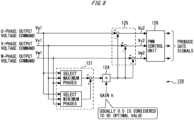
- Fig. 8 is a diagram for describing a control procedure of a three-phase voltage inverter in a control device 120 of a power conversion device 100 in related art.
- the control device 120 has an addition value calculation unit 121, a control amount calculation unit 124, an output voltage command signal control unit 125, and a PWM control unit 126.
- the addition value calculation unit 121 selects maximum phases and minimum phases of three phases of sinusoidal output voltage command signals Vu1, Vv1, and Vw1 and calculates respective addition values of the selected maximum phases and minimum phases.
- the control amount calculation unit 124 multiplies, by a coefficient k (gain k), the addition values obtained by the addition value calculation unit 121 and obtains control amounts for the output voltage command signals Vu1, Vv1, and Vw1. As described above, in a case where the coefficient k (gain k) is 0.5, the amplitude is most reduced.
- the output voltage command signal control unit 125 obtains output voltage command signals Vu2, Vv2, and Vw2 which result from subtraction of the control amounts obtained by the control amount calculation unit 124 from the three phases of the output voltage command signals Vu1, Vv1, and Vw1.
- the PWM control unit 126 compares the output voltage command signals Vu2, Vv2, and Vw2 obtained by the output voltage command signal control unit 125 with a carrier signal as a triangle wave, performs PWM control, and produces gate signals.
- a coefficient k (gain k) of 0.5 is considered to be optimal in order to obtain a more output voltage amplitude.
- a reason why 0.5 is optimal will be described.
- PV photovoltaics
- ESS energy storage system
- the above third harmonic superimposition is realized by subtracting k ⁇ (maximum phase + minimum phase) (k is a coefficient) from each phase of three phases of sinusoidal waves.
- k denotes the coefficient
- ⁇ sin ⁇ + sin( ⁇ + 2 ⁇ /3) ⁇ denotes (maximum phase + minimum phase) in ⁇ /6 ⁇ ⁇ ⁇ ⁇ /2.
- k which minimizes the amplitude is obtained
- a numerical value of 0.5 comes out.
- the optimal value of the coefficient k becomes 0.5.
- the above problem is an extreme value problem in calculus. That is, the above problem is an extremum problem which has two stages and in which when a function of f( ⁇ ) is given, this function is differentiated, ⁇ is obtained at which the derivative value becomes zero, and k is then obtained which minimizes the obtained value.
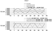
- Fig. 9 is a diagram for describing a reason why 0.5 is optimal as the gain k in the control procedure illustrated in Fig. 8 .
- Fig. 9A is a diagram illustrating states of sinusoidal waves of U phase, V phase, and W phase and k ⁇ (maximum phase + minimum phase) in a case where k is 0.5.
- Fig. 9B is a diagram illustrating states of changes in the function of f( ⁇ ) in a case where k is 0.5.
- a sinusoidal wave by a solid line represents the U phase as sin ⁇
- a sinusoidal wave by a broken line with short dashes represents the V phase as sin( ⁇ - 2 ⁇ /3)
- a sinusoidal wave by a rough broken line represents the W phase as sin( ⁇ - 4 ⁇ /3).
- a one-dot chain line represents k ⁇ (maximum phase + minimum phase) in a case where k is 0.5.
- a solid line represents the U phase as sin ⁇ - k ⁇ (maximum phase + minimum phase)
- a broken line with short dashes represents the V phase as sin( ⁇ - 2 ⁇ /3) - k ⁇ (maximum phase + minimum phase)
- a rough broken line represents the W phase as sin( ⁇ - 4 ⁇ /3) - k ⁇ (maximum phase + minimum phase).
- Fig. 9B illustrates the results of subtraction of the control amounts from the sinusoidal output voltage command signals.
- Fig. 9B illustrates shapes of sinusoidal waves in which peaks are slightly recessed.
- k 0.5.
- the recesses in the peaks of the sinusoidal waves are decreased.
- k is increased like 0.6, 0.7, 0.8, ..., conversely, the recesses in the peaks of the sinusoidal waves are excessively increased.
- the fact that 0.5 is optimal as the gain k only means that 0.5 is optimal for the purpose of earning the output voltage amplitude as much as possible.
- the gain k of 0.5 is not necessarily optimal.
- an object of the present disclosure is to improve conversion efficiency of a three-phase voltage inverter by a simpler procedure than a procedure in related art in which an amplitude of the third harmonic wave is superimposed.
- a power conversion device includes: a three-phase voltage inverter which converts a DC voltage from a DC power source to three-phase AC voltages and outputs the three-phase AC voltages to a power system; an addition value calculation unit which obtains addition values of maximum phases and minimum phases of first output voltage command signals as three phases of sinusoidal output voltage command signals in the three-phase AC voltages; an effective value calculation unit which obtains an effective value of an output voltage command based on the three phases of the first output voltage command signals; coefficient determination means for determining a coefficient which minimizes power loss of the three-phase voltage inverter based on the effective value obtained by the effective value calculation unit, a value of the DC voltage, and an output power factor command corresponding to a request for an output to the power system; a control amount calculation unit which obtains control amounts by multiplying the addition values obtained by the addition value calculation unit by the coefficient determined by the coefficient determination means; an output voltage command signal control unit which obtains second output voltage command signals as signals resulting from subtraction of the control amounts obtained by the control
- the effective value calculation unit may obtain the effective value by converting the three phases of the first output voltage command signals to a d-axis voltage command signal and a q-axis voltage command signal and by taking a square root of a sum of a square of the d-axis voltage command signal resulting from conversion and a square of the q-axis voltage command signal resulting from the conversion.
- the coefficient determination means may determine the coefficient corresponding to a combination of the effective value, the value of the DC voltage, and the output power factor command based on a coefficient table which defines a relationship among the effective value, the value of the DC voltage, the output power factor command, and the coefficient which minimizes the power loss of the three-phase voltage inverter.
- the coefficient determination means may determine the coefficient which minimizes the power loss of the three-phase voltage inverter based on a function which has, as parameters, the effective value, the value of the DC voltage, and the output power factor command.
- a method of controlling a three-phase voltage inverter is a method of controlling a three-phase voltage inverter in a power conversion device which includes the three-phase voltage inverter converting a DC voltage from a DC power source to three-phase AC voltages and outputting the three-phase AC voltages to a power system, the method including: an addition value calculation step of obtaining addition values of maximum phases and minimum phases of first output voltage command signals as three phases of sinusoidal output voltage command signals in the three-phase AC voltages; an effective value calculation step of obtaining an effective value of an output voltage command based on the three phases of the first output voltage command signals; a coefficient determination step of determining a coefficient which minimizes power loss of the three-phase voltage inverter based on the effective value obtained by the effective value calculation step, a value of the DC voltage, and an output power factor command corresponding to a request for an output to the power system; a control amount calculation step of obtaining control amounts by multiplying the addition values obtained by the addition value calculation step by the coefficient determined by the
- a control program of a three-phase voltage inverter causes a computer to execute processes of the method of controlling a three-phase voltage inverter.
- conversion efficiency of a three-phase voltage inverter can be improved by a simpler procedure than a procedure in related art in which an amplitude of the third harmonic wave is superimposed.
- a power conversion device, a method of controlling a three-phase voltage inverter, and a control program of the present disclosure will hereinafter be described by using drawings.
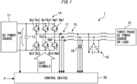
- Fig. 1 is a diagram illustrating a configuration example of a power conversion device 1 according to a first embodiment.
- the power conversion device (PCS: power conditioning subsystem) 1 is connected with a DC power source 11 and a power system 12.
- the power conversion device 1 converts DC power supplied from the DC power source 11 to AC power via a three-phase voltage inverter 14 described later and outputs that to the power system 12.
- the DC power source 11 is connected with a DC end of the power conversion device 1 and supplies DC power to the power conversion device 1 via the DC end of the power conversion device 1.
- the DC power source 11 is a solar power generation device (PV) including a solar panel, a storage battery (ESS), or the like, for example.
- PV solar power generation device
- ESS storage battery
- the DC power source 11 may be a DC power source system or the like formed with a wind power generator, an AC/DC converter, and so forth, for example.
- the power system 12 is connected with an AC end of the power conversion device 1 and is connected with a power plant, a factory, or the like (a three-phase AC power source, a load, or the like) via power transmission lines.
- the power conversion device 1 has to conform to a presently requested power factor in power transmission to the power system 12.
- the power conversion device 1 has a smoothing capacitor 13, the three-phase voltage inverter 14, a reactor 15, a capacitor 16, an ammeter 17, and a voltmeter 18.
- the smoothing capacitor 13 is a capacitor which is connected between a positive electrode side and a negative electrode side of the DC power source 11 and is for smoothing a fluctuation in a voltage VH across terminals.
- the three-phase voltage inverter 14 converts a DC voltage from the DC power source 11 to three-phase AC voltages and outputs those to the power system 12.
- the three-phase voltage inverter 14 has a circuit in which three legs (U-phase leg, V-phase leg, and W-phase leg) are connected in parallel. Each of the legs is formed by connecting, in series, two arms in each of which a switching element and a freewheeling diode are connected in reversely parallel. Each of the legs is in parallel connected between the positive electrode side and the negative electrode side of the DC power source 11.
- the U-phase leg has a switching element Qu1 and a switching element Qu2.
- the switching element Qu1 and the switching element Qu2 are connected in series in order from the positive electrode side of the DC power source 11.
- An intermediate point between the switching element Qu1 and the switching element Qu2 is electrically connected with a U-phase terminal of the power system 12.
- the switching element Qu1 and a freewheeling diode Du1 are connected in reversely parallel.
- the switching element Qu2 and a freewheeling diode Du2 are connected in reversely parallel.
- the V-phase leg has a switching element Qv1 and a switching element Qv2.
- the switching element Qv1 and the switching element Qv2 are connected in series in order from the positive electrode side of the DC power source 11.
- An intermediate point between the switching element Qv1 and the switching element Qv2 is electrically connected with a V-phase terminal of the power system 12.
- the switching element Qv1 and a freewheeling diode Dv1 are connected in reversely parallel.
- the switching element Qv2 and a freewheeling diode Dv2 are connected in reversely parallel.
- the W-phase leg has a switching element Qw1 and a switching element Qw2.
- the switching element Qw1 and the switching element Qw2 are connected in series in order from the positive electrode side of the DC power source 11.
- An intermediate point between the switching element Qw1 and the switching element Qw2 is electrically connected with a W-phase terminal of the power system 12.
- the switching element Qw1 and a freewheeling diode Dw1 are connected in reversely parallel.
- the switching element Qw2 and a freewheeling diode Dw2 are connected in reversely parallel.
- each of the switching elements Qu1 to Qw2 an IGBT (insulated gate bipolar transistor) is employed.
- a switching element is not limited to this, but a MOSFET (metal-oxide-semiconductor field-effect transistor) or the like may be used.
- the reactor 15 is a smoothing element provided between the intermediate point of each of the legs of the three-phase voltage inverter 14 and the power system 12.
- the capacitor 16 constitutes, together with the reactor 15, a filter circuit which reduces a ripple.
- the ammeter 17 detects an output current of the three-phase voltage inverter 14. A value of the detected output current is obtained by the control device 20.
- the voltmeter 18 detects an output voltage (line voltage) of the three-phase voltage inverter 14. A value of the detected output voltage is obtained by the control device 20.
- the control device 20 has a processor, which is not illustrated, such as a CPU (central processing unit) or a GPU (graphics processing unit) which acts by execution of a program, for example.
- the control device 20 causes the processor not illustrated to act by executing a predetermined program stored in a storage unit 30 (see Fig. 2 ) described later and thereby integrally controls an action of the power conversion device 1, for example.
- control device 20 is provided to an internal portion or an external portion of the power conversion device 1 and is electrically connected with elements, including the three-phase voltage inverter 14, of the power conversion device 1 in a wired or wireless manner although wiring or the like is not illustrated in Fig. 1 .
- control device 20 may be realized as a function of an inverter control circuit which is not illustrated.
- the control device 20 obtains the voltage VH across terminals which is detected by a voltmeter not illustrated, the output current detected by the ammeter 17, the line voltage detected by the voltmeter 18, and a power command P.
- the power command P is a command corresponding to a request for an output to the power system 12 and is obtained from an external portion (for example, a host device or the like) of the power conversion device 1.
- the control device 20 generates a gate signal for driving each of the switching elements Qu1 to Qw2. An action of the three-phase voltage inverter 14 is controlled by the generated gate signals.
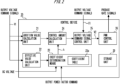
- Fig. 2 is a diagram illustrating a configuration example of the control device 20 in the power conversion device 1 illustrated in Fig. 1 .
- the control device 20 functions as an addition value calculation unit 21, an effective value calculation unit 22, coefficient determination means 23, a control amount calculation unit 24, an output voltage command signal control unit 25, and a PWM control unit 26. Further, the control device 20 has the storage unit 30.
- the addition value calculation unit 21 obtains three phases of sinusoidal output voltage command signals V1 in the three-phase AC voltages, selects maximum phases and minimum phases of the obtained three phases of the output voltage command signals V1, and calculates addition values of the selected maximum phases and minimum phases.
- the output voltage command signals V1 are indicated by one line but are actually divided into three phases of a U-phase output voltage command signal Vu1, a V-phase output voltage command signal Vv1, and a W-phase output voltage command signal Vw1.
- the addition value calculation unit 21 outputs the obtained addition values to the control amount calculation unit 24.
- the three phases of the output voltage command signals V1 (the U-phase output voltage command signal Vu1, the V-phase output voltage command signal Vv1, and the W-phase output voltage command signal Vw1) are one example of "first output voltage command signal".
- the effective value calculation unit 22 obtains an effective value of an output voltage command based on the three phases of the sinusoidal output voltage command signals V1 (the U-phase output voltage command signal Vu1, the V-phase output voltage command signal Vv1, and the W-phase output voltage command signal Vw1) in the three-phase AC voltages.
- the effective value calculation unit 22 converts the three phases of the output voltage command signals V1 (the U-phase output voltage command signal Vu1, the V-phase output voltage command signal Vv1, and the W-phase output voltage command signal Vw1) to a d-axis voltage command signal Vd and a q-axis voltage command signal Vq.
- the effective value calculation unit 22 takes the square root of the sum of the square of the d-axis voltage command signal Vd and the square of the q-axis voltage command signal Vq, the d-axis voltage command signal Vd and the q-axis voltage command signal Vq resulting from the conversion, and thereby obtains the effective value.
- the effective value calculation unit 22 outputs the obtained effective value of the output voltage command to the coefficient determination means 23.
- the coefficient determination means 23 determines a coefficient k which minimizes power loss of the three-phase voltage inverter 14 based on the effective value obtained by the effective value calculation unit 22, the value of the DC voltage, and an output power factor command corresponding to the request for the output to the power system.
- the determined coefficient k will also be referred to as "gain k". Note that the output power factor command is obtained from an external portion such as a host device not illustrated.
- the coefficient determination means 23 has a coefficient table 23a which defines the relationship among the above effective value, the value of the DC voltage, the output power factor command, and the coefficient which minimizes the power loss of the three-phase voltage inverter. Note that contents of the coefficient table 23a are in advance obtained based on analyses and actual operation data such that the efficiency becomes highest in each condition. Note that the coefficient table 23a may be retained by the storage unit 30.
- the coefficient determination means 23 determines the coefficient k which minimizes the power loss of the three-phase voltage inverter 14 and which corresponds to a combination of the above effective value, the value of the DC voltage, and the output power factor command.
- the coefficient determination means 23 outputs the determined coefficient k to the control amount calculation unit 24.
- the control amount calculation unit 24 obtains the addition values obtained by the addition value calculation unit 21 and the coefficient k determined by the coefficient determination means 23, multiplies the obtained addition values by the coefficient k, and thereby obtains control amounts for the output voltage command signals V1.
- the control amount calculation unit 24 outputs the obtained control amounts to the output voltage command signal control unit 25.
- the output voltage command signal control unit 25 respectively subtracts the control amounts obtained by the control amount calculation unit 24 from the three phases of the output voltage command signals V1 and thereby obtains three phases of output voltage command signals V2 as signals resulting from the subtraction.
- the output voltage command signals V2 are indicated by one line but are actually divided into three phases of a U-phase output voltage command signal Vu2, a V-phase output voltage command signal Vv2, and a W-phase output voltage command signal Vw2.
- the output voltage command signal control unit 25 outputs the obtained output voltage command signals V2 (the U-phase output voltage command signal Vu2, the V-phase output voltage command signal Vv2, and the W-phase output voltage command signal Vw2) to the PWM control unit 26.
- the three phases of the output voltage command signals V2 are one example of "second output voltage command signal".
- the PWM control unit 26 generates the gate signals based on the three phases of the output voltage command signals V2 obtained by the output voltage command signal control unit 25 and a triangle-wave-shaped carrier signal.
- the PWM control unit 26 outputs the generated gate signals to the three-phase voltage inverter 14.
- the storage unit 30 is a volatile or non-volatile storage medium such as an HDD (hard disk drive), an SDD (solid state drive), or a semiconductor memory, for example, and stores programs necessary for actions of units of the control device 20, for example. Further, the storage unit 30 stores values obtained and results calculated by the units of the control device 20, coefficient tables and functions which are necessary for calculation, and so forth.
- the storage unit 30 is connected with the units of the control device 20 by a bus or the like not illustrated, for example. Note that the storage unit 30 may be provided to an external portion of the control device 20, may be connected with the control device 20 in a wired or wireless manner, and may be an external storage medium or the like such as a memory card or a DVD (digital versatile disc) or an online storage or the like.
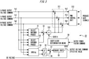
- Fig. 3 is a diagram for describing a control procedure in the control device 20 illustrated in Fig. 2 .
- the control in Fig. 3 is started when an operation of the power conversion device 1 is started, for example. In the following, the control illustrated in Fig. 3 will be described (see also Fig. 2 , appropriately).
- step S1 the addition value calculation unit 21 of the control device 20 selects the maximum phases of the three phases of the output voltage command signals V1 (the U-phase output voltage command signal Vu1, the V-phase output voltage command signal Vv1, and the W-phase output voltage command signal Vw1).
- step S2 the addition value calculation unit 21 of the control device 20 selects the minimum phases of the three phases of the output voltage command signals V1 (the U-phase output voltage command signal Vu1, the V-phase output voltage command signal Vv1, and the W-phase output voltage command signal Vw1).
- step S3 the addition value calculation unit 21 of the control device 20 adds the maximum phases selected in step S 1 to the minimum phases selected in step S2 and thereby obtains the addition values.
- step S4 the effective value calculation unit 22 of the control device 20 performs conversion from three phases to two phases (dq conversion) for the three phases of the output voltage command signals V1 (the U-phase output voltage command signal Vu1, the V-phase output voltage command signal Vv1, and the W-phase output voltage command signal Vw1). Accordingly, the effective value calculation unit 22 converts the three phases of the output voltage command signals V1 (the U-phase output voltage command signal Vu1, the V-phase output voltage command signal Vv1, and the W-phase output voltage command signal Vw1) to the d-axis voltage command signal Vd and the q-axis voltage command signal Vq.
- step S5 the effective value calculation unit 22 of the control device 20 obtains the square value of the value of the d-axis voltage command signal Vd.
- step S6 the effective value calculation unit 22 of the control device 20 obtains the square value of the value of the q-axis voltage command signal Vq.
- step S7 the effective value calculation unit 22 of the control device 20 obtains the value resulting from addition of the value obtained in step S5 and the value obtained in step S6.
- step S8 the effective value calculation unit 22 of the control device 20 obtains the value of the square root of the value obtained in step S7.
- the value obtained in step S8 becomes the effective value (amplitude) of the output voltage command.
- step S9 the coefficient determination means 23 of the control device 20 determines the coefficient k (gain k) which minimizes the power loss of the three-phase voltage inverter 14 based on the effective value obtained in step S8, the value of the DC voltage, and the output power factor command corresponding to the request for the output to the power system 12.
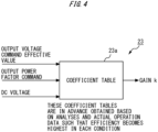
- Fig. 4 is a diagram for describing a coefficient determination procedure in the coefficient determination means 23, which is indicated by step S9 in Fig. 3 .
- the coefficient determination means 23 has the coefficient table 23a which defines the relationship among the effective value (amplitude) of the output voltage command, the value of the DC voltage, the output power factor command, and the coefficient which minimizes the power loss of the three-phase voltage inverter.
- the output power factor command is obtained from an external portion such as a host device not illustrated.
- the contents of the coefficient table 23a are in advance obtained based on analyses and actual operation data such that the efficiency becomes highest in each condition.
- the coefficient determination means 23 determines the gain k which minimizes the power loss of the three-phase voltage inverter 14 and which corresponds to the combination of the effective value, the value of the DC voltage, and the output power factor command.
- step S10 the control amount calculation unit 24 of the control device 20 obtains the control amounts by multiplying the addition values obtained in step S3 by the gain k obtained in step S10.
- step S 11 the output voltage command signal control unit 25 of the control device 20 respectively subtracts the control amounts obtained in step S10 from the three phases of the output voltage command signals V1 (the U-phase output voltage command signal Vu1, the V-phase output voltage command signal Vv1, and the W-phase output voltage command signal Vw1). Accordingly, the output voltage command signal control unit 25 obtains the output voltage command signals V2 (the U-phase output voltage command signal Vu2, the V-phase output voltage command signal Vv2, and the W-phase output voltage command signal Vw2).
- step S12 the PWM control unit 26 of the control device 20 compares the output voltage command signals V2 (the U-phase output voltage command signal Vu2, the V-phase output voltage command signal Vv2, and the W-phase output voltage command signal Vw2) obtained in step S11 with the triangle-wave-shaped carrier signal.
- the PWM control unit 26 performs a comparison in magnitude between the U-phase output voltage command signal Vu2 and a carrier signal C (triangular waveform) having a predetermined carrier frequency f. Then, the PWM control unit 26 generates the gate signal such that the switching element Qu1 related to an upper arm is turned ON when the triangular waveform is smaller and the switching element Qu2 related to a lower arm is turned ON when the triangular waveform is larger. Note that the same applies to the V phase and the W phase. Accordingly, the gate signals are produced which maximizes the efficiency of the three-phase voltage inverter 14.
- the coefficient determination means 23 determines the gain k which minimizes the power loss of the three-phase voltage inverter 14 and which corresponds to the combination of the effective value of the output voltage command, the value of the DC voltage, and the output power factor command (S9). Then, the control amount calculation unit 24 obtains the control amounts by multiplying, by the gain k, the addition values of the maximum phases and the minimum phases of the three phases of the output voltage command signals V1 (S10). Then, the output voltage command signal control unit 25 subtracts the control amounts from the three phases of the output voltage command signals V1 and thereby obtains the output voltage command signals V2 (S 11). Then, the PWM control unit 26 generates the gate signals based on the output voltage command signals V2 and the triangle-wave-shaped carrier signal (S12).
- the gain k which maximizes the efficiency of the three-phase voltage inverter 14 can be obtained by simpler computation than a procedure in related art in which an amplitude of the third harmonic wave is superimposed. Accordingly, conversion efficiency of the three-phase voltage inverter can be improved by a simpler procedure than a procedure in related art in which an amplitude of the third harmonic wave is superimposed.
- Fig. 5 is a diagram illustrating a configuration example of a control device 20B in a power conversion device 1B according to a second embodiment.
- the same reference characters are given to configurations similar to the first embodiment illustrated in Fig. 1 to Fig. 4 , and detailed descriptions thereof will not be repeated or will be simplified.
- the coefficient determination means 23B determines the coefficient k (gain k) which minimizes the power loss of the three-phase voltage inverter 14 based on a function 23b which has, as parameters, an effective value (voltage command amplitude) x of the output voltage command, a value y of the DC voltage, and an output power factor command z. That is, in step S9 in Fig. 3 , the coefficient determination means 23B determines the coefficient k (gain k) based on the function 23b which has, as the parameters, the effective value x obtained in step S8, the value y of the DC voltage, and the output power factor command z corresponding to the request for the output to the power system 12. The coefficient determination means 23B outputs the determined coefficient k to the control amount calculation unit 24.
- Fig. 6 is a diagram for describing a coefficient determination procedure in the coefficient determination means 23B, which is illustrated in Fig. 5 .
- the coefficient determination means 23B has the function 23b which has, as the parameters, the effective value (voltage command amplitude) x of the output voltage command, the value y of the DC voltage, and the output power factor command z.
- the function 23b is a function which approximates numerical values of the coefficient table 23a in the first embodiment illustrated in Fig. 1 to Fig. 4 (approximation function). Contents of the function 23b are in advance obtained based on analyses and actual operation data such that the efficiency becomes highest in each condition.
- the function 23b may be retained by the coefficient determination means 23B or may be retained by the storage unit 30. Further, the function 23b may in advance be obtained by computation or the like or may be obtained each time by computation or the like by the coefficient determination means 23B such that the efficiency becomes highest in each condition or based on the contents of the coefficient table 23a.
- the second embodiment illustrated in Fig. 5 and Fig. 6 provides similar effects to the first embodiment illustrated in Fig. 1 to Fig. 4 .
- the capacity of a memory can be saved more than the first embodiment illustrated in Fig. 1 to Fig. 4 .
- the coefficient table 23a in the embodiment illustrated in Fig. 1 to Fig. 4 has three parameters, and because the three parameters have respective fluctuation ranges, the coefficient table 23a has to retain information of the coefficient k for the amount corresponding to the three parameters which respectively fluctuate.
- the coefficient table 23a in the embodiment illustrated in Fig. 1 to Fig. 4 consumes a much more capacity of the memory than a usual case.
- the coefficient determination means 23B which has obtained the three parameters (x, y, z) performs computation about the three parameters (x, y, z) based on the function 23b and thereby determines the numerical values which approximate the numerical values of the coefficient table 23a illustrated in Fig. 1 to Fig. 4 by the function.
- the capacity of the memory can be saved more than the embodiment illustrated in Fig. 1 to Fig. 4 .
- Fig. 7 is a conceptual diagram illustrating a hardware configuration example of a processing circuit provided to the control devices 20 and 20B in the embodiments illustrated in Fig. 1 to Fig. 6 .
- the processing circuit includes at least one processor 91 and at least one memory 92.
- the processing circuit includes at least one piece of dedicated hardware 93.
- each of the functions is realized by software, firmware, or a combination of software and firmware. At least one of the software and the firmware is described as a program. At least one of the software and the firmware is stored in the memory 92.
- the processor 91 realizes each of the functions by reading out and executing programs stored in the memory 92.
- the processing circuit includes the dedicated hardware 93
- the processing circuit is provided as a single circuit, a composite circuit, a processor formed as a program, or a combination of those, for example.
- Each of the functions is realized by the processing circuit.
- control devices 20 and 20B may be implemented with hardware or may be implemented as a program to be executed by the processor. That is, the control devices 20 and 20B are capable of being realized by a computer and a program, and the program is capable of being stored in a storage medium and of being provided through a network.
- the embodiments illustrated in Fig. 1 to Fig. 7 are separated into the first embodiment illustrated in Fig. 1 to Fig. 4 and the second embodiment illustrated in Fig. 5 and Fig. 6 ; however, a part or whole of each of those embodiments may be combined in series or in parallel. That is, the control device 20 or 20B may have the coefficient determination means 23 and the coefficient determination means 23B as being combined in series or in parallel, and the coefficient k may be determined by combining those determination procedures in series or in parallel.
- the embodiments are combined, and the combined embodiments can thereby provide functions and effects to be provided by each of the embodiments which have not yet been combined.
- the two-level three-phase voltage inverter 14 having a circuit in which three legs are connected in parallel, the leg having two arms in each of which the switching element and the freewheeling diode are connected in reversely parallel and which are connected in series; however, embodiments are not limited to this.
- the present disclosure is applicable to a neutral-point clamped three-level inverter or a neutral-point switching three-level inverter, for example, as long as an inverter is a three-phase voltage inverter which converts a direct current to a three-phase alternating current.
- the present disclosure is also capable of being realized as a method of controlling a three-phase voltage inverter in which processing steps in the units of the control devices 20 and 20B are performed.
- the present disclosure is also capable of being realized as a control program of a three-phase voltage inverter, the control program causing a computer to execute processing steps in the units of the control devices 20 and 20B.
- control program may be distributed while being stored in a removable disk or the like such as a CD (compact disc), a DVD (digital versatile disc), or a USB (universal serial bus) memory.
- control program may be uploaded to a network via a network interface or the like which is provided to the control device 20 or 20B and is not illustrated or may be downloaded from a network and stored in the storage unit 30 or the like.
Landscapes
- Engineering & Computer Science (AREA)
- Power Engineering (AREA)
- Inverter Devices (AREA)
- Physics & Mathematics (AREA)
- Electromagnetism (AREA)
Abstract
Description
- The present invention relates to a power conversion device, a method of controlling a three-phase voltage inverter, and a control program.
- In related art, as a manner of controlling an inverter, PWM (pulse width modulation) control has been known. In a three-phase voltage inverter, a voltage command signal of a sinusoidal wave is generated in each phase of U phase, V phase, and W phase of three phases, and each of those three phases of the voltage command signals is compared with a carrier signal as a triangle wave for achieving the PWM control of the three phases.
- Superimposition of the third harmonic wave, which is at the frequency three times a fundamental wave, on each of the three phases of the voltage command signal causes a waveform of the voltage command signal to change, so that a condition of a gate pulse, that is, an ON-OFF ratio of an inverter output voltage is changed. As a result, a time ratio of a current, which flows through a path having a switching element and a path having a diode in the inverter, is also changed. Further, because a difference in power loss may occur depending on paths of a current, a difference may eventually occur to conversion efficiency of the inverter.
- Thus, there has been suggested a manner of controlling an inverter in which in order to improve conversion efficiency of a three-phase voltage inverter, an amplitude of the third harmonic wave which minimizes power loss is determined and the determined amplitude of the third harmonic wave is superimposed on three phases of voltage command signals (for example, see PTL 1).
- [PTL 1]
JP 6733816 B - However, in a manner in related art in which an amplitude of the third harmonic wave at the frequency three times a fundamental wave is superimposed on three phases of voltage command signals, computation possibly becomes complicated.
- Meanwhile, in related art, as for a three-phase voltage inverter, a procedure has been known in which in order to obtain a wide output voltage range, a value resulting from multiplication, by a coefficient, of the addition value of the maximum phase and the minimum phase of a sinusoidal output voltage command signal is subtracted from the output voltage command signal. In this case, the fact has been known that the amplitude is most reduced in a case where the above coefficient is set to 0.5.
-
Fig. 8 is a diagram for describing a control procedure of a three-phase voltage inverter in acontrol device 120 of apower conversion device 100 in related art. InFig. 8 , thecontrol device 120 has an additionvalue calculation unit 121, a controlamount calculation unit 124, an output voltage commandsignal control unit 125, and aPWM control unit 126. - The addition
value calculation unit 121 selects maximum phases and minimum phases of three phases of sinusoidal output voltage command signals Vu1, Vv1, and Vw1 and calculates respective addition values of the selected maximum phases and minimum phases. - The control
amount calculation unit 124 multiplies, by a coefficient k (gain k), the addition values obtained by the additionvalue calculation unit 121 and obtains control amounts for the output voltage command signals Vu1, Vv1, and Vw1. As described above, in a case where the coefficient k (gain k) is 0.5, the amplitude is most reduced. - The output voltage command
signal control unit 125 obtains output voltage command signals Vu2, Vv2, and Vw2 which result from subtraction of the control amounts obtained by the controlamount calculation unit 124 from the three phases of the output voltage command signals Vu1, Vv1, and Vw1. - The
PWM control unit 126 compares the output voltage command signals Vu2, Vv2, and Vw2 obtained by the output voltage commandsignal control unit 125 with a carrier signal as a triangle wave, performs PWM control, and produces gate signals. - As described above, a coefficient k (gain k) of 0.5 is considered to be optimal in order to obtain a more output voltage amplitude. Here, a reason why 0.5 is optimal will be described. For example, in third harmonic superimposition which is actually practiced in solar power generation (PV: photovoltaics), a storage battery (ESS: energy storage system), and so forth, not a sinusoidal wave at a three times higher frequency but a signal which is a modulated wave itself being processed is used. Thus, the above third harmonic superimposition which is actually practiced is not "third harmonic superimposition", strictly speaking.
- Specifically, the above third harmonic superimposition is realized by subtracting k × (maximum phase + minimum phase) (k is a coefficient) from each phase of three phases of sinusoidal waves. In this case, the optimal value of the coefficient k can be obtained by solving a problem of "obtaining the value of k which minimizes the amplitude of f(θ) = sinθ - k{ sinθ + sin(θ + 2π/3)} in π/6 ≤ θ ≤ π/2".
- In the formula in the above problem, k denotes the coefficient, and {sinθ + sin(θ + 2π/3)} denotes (maximum phase + minimum phase) in π/6 ≤ θ ≤ π/2. In the above formula, when k which minimizes the amplitude is obtained, a numerical value of 0.5 comes out. Thus, the optimal value of the coefficient k becomes 0.5. Note that the above problem is an extreme value problem in calculus. That is, the above problem is an extremum problem which has two stages and in which when a function of f(θ) is given, this function is differentiated, θ is obtained at which the derivative value becomes zero, and k is then obtained which minimizes the obtained value.
-
Fig. 9 is a diagram for describing a reason why 0.5 is optimal as the gain k in the control procedure illustrated inFig. 8 .Fig. 9A is a diagram illustrating states of sinusoidal waves of U phase, V phase, and W phase and k × (maximum phase + minimum phase) in a case where k is 0.5.Fig. 9B is a diagram illustrating states of changes in the function of f(θ) in a case where k is 0.5. - In
Fig. 9A , a sinusoidal wave by a solid line represents the U phase as sinθ, a sinusoidal wave by a broken line with short dashes represents the V phase as sin(θ - 2π/3), and a sinusoidal wave by a rough broken line represents the W phase as sin(θ - 4π/3). Further, a one-dot chain line represents k × (maximum phase + minimum phase) in a case where k is 0.5. - Further, in
Fig. 9B , a solid line represents the U phase as sinθ - k × (maximum phase + minimum phase), a broken line with short dashes represents the V phase as sin(θ - 2π/3) - k × (maximum phase + minimum phase), and a rough broken line represents the W phase as sin(θ - 4π/3) - k × (maximum phase + minimum phase). - That is,
Fig. 9B illustrates the results of subtraction of the control amounts from the sinusoidal output voltage command signals.Fig. 9B illustrates shapes of sinusoidal waves in which peaks are slightly recessed. The example illustrated inFig. 9B is an example of a case where k = 0.5. Here, for example, in a case where k is decreased like 0.4, 0.3, 0.2, ..., the recesses in the peaks of the sinusoidal waves are decreased. On the other hand, for example, in a case where k is increased like 0.6, 0.7, 0.8, ..., conversely, the recesses in the peaks of the sinusoidal waves are excessively increased. Thus, as illustrated inFig. 9B , the optimally recessed situation is obtained when k = 0.5. - When superimposition is performed for a sinusoidal wave with a unit amplitude with the gain k being 0.5, the local maximum value becomes (√3)/2. Accordingly, in an ideal state (where even a modulation degree of one can be used without taking into consideration dead time or the like), because an output of a fundamental wave amplitude of 2/(√3) = 1.1547 is possible, effects can be obtained which are equivalent to third harmonic superimposition of "a type in which the third harmonic wave is actually added". Thus, as a procedure of simply realizing a method which can obtain effects equivalent to the above-described method of superimposing a three times higher frequency (as known as third harmonic superimposition), a procedure is employed in which the gain k is set to 0.5.
- However, the fact that 0.5 is optimal as the gain k only means that 0.5 is optimal for the purpose of earning the output voltage amplitude as much as possible. However, for the purpose of maximizing efficiency of a three-phase voltage inverter, the gain k of 0.5 is not necessarily optimal.
- Accordingly, an object of the present disclosure is to improve conversion efficiency of a three-phase voltage inverter by a simpler procedure than a procedure in related art in which an amplitude of the third harmonic wave is superimposed.
- A power conversion device according to one aspect includes: a three-phase voltage inverter which converts a DC voltage from a DC power source to three-phase AC voltages and outputs the three-phase AC voltages to a power system; an addition value calculation unit which obtains addition values of maximum phases and minimum phases of first output voltage command signals as three phases of sinusoidal output voltage command signals in the three-phase AC voltages; an effective value calculation unit which obtains an effective value of an output voltage command based on the three phases of the first output voltage command signals; coefficient determination means for determining a coefficient which minimizes power loss of the three-phase voltage inverter based on the effective value obtained by the effective value calculation unit, a value of the DC voltage, and an output power factor command corresponding to a request for an output to the power system; a control amount calculation unit which obtains control amounts by multiplying the addition values obtained by the addition value calculation unit by the coefficient determined by the coefficient determination means; an output voltage command signal control unit which obtains second output voltage command signals as signals resulting from subtraction of the control amounts obtained by the control amount calculation unit respectively from the three phases of the first output voltage command signals; and a PWM control unit which generates gate signals based on the second output voltage command signals obtained by the output voltage command signal control unit and a triangle-wave-shaped carrier signal.
- Note that in the power conversion device according to one aspect, the effective value calculation unit may obtain the effective value by converting the three phases of the first output voltage command signals to a d-axis voltage command signal and a q-axis voltage command signal and by taking a square root of a sum of a square of the d-axis voltage command signal resulting from conversion and a square of the q-axis voltage command signal resulting from the conversion.
- Further, in the power conversion device according to one aspect, the coefficient determination means may determine the coefficient corresponding to a combination of the effective value, the value of the DC voltage, and the output power factor command based on a coefficient table which defines a relationship among the effective value, the value of the DC voltage, the output power factor command, and the coefficient which minimizes the power loss of the three-phase voltage inverter.
- Further, in the power conversion device according to one aspect, the coefficient determination means may determine the coefficient which minimizes the power loss of the three-phase voltage inverter based on a function which has, as parameters, the effective value, the value of the DC voltage, and the output power factor command.
- A method of controlling a three-phase voltage inverter according to one aspect is a method of controlling a three-phase voltage inverter in a power conversion device which includes the three-phase voltage inverter converting a DC voltage from a DC power source to three-phase AC voltages and outputting the three-phase AC voltages to a power system, the method including: an addition value calculation step of obtaining addition values of maximum phases and minimum phases of first output voltage command signals as three phases of sinusoidal output voltage command signals in the three-phase AC voltages; an effective value calculation step of obtaining an effective value of an output voltage command based on the three phases of the first output voltage command signals; a coefficient determination step of determining a coefficient which minimizes power loss of the three-phase voltage inverter based on the effective value obtained by the effective value calculation step, a value of the DC voltage, and an output power factor command corresponding to a request for an output to the power system; a control amount calculation step of obtaining control amounts by multiplying the addition values obtained by the addition value calculation step by the coefficient determined by the coefficient determination step; an output voltage command signal control step of obtaining second output voltage command signals as signals resulting from subtraction of the control amounts obtained by the control amount calculation step respectively from the three phases of the first output voltage command signals; and a PWM control step of generating gate signals based on the second output voltage command signals obtained by the output voltage command signal control step and a triangle-wave-shaped carrier signal.
- A control program of a three-phase voltage inverter according to one aspect causes a computer to execute processes of the method of controlling a three-phase voltage inverter.
- In the present disclosure, conversion efficiency of a three-phase voltage inverter can be improved by a simpler procedure than a procedure in related art in which an amplitude of the third harmonic wave is superimposed.
-
- [
Fig. 1 ]
Fig. 1 is a diagram illustrating a configuration example of a power conversion device according to a first embodiment. - [
Fig. 2 ]
Fig. 2 is a diagram illustrating a configuration example of a control device in the power conversion device illustrated inFig. 1 . - [
Fig. 3 ]
Fig. 3 is a diagram for describing a control procedure of a three-phase voltage inverter in the control device illustrated inFig. 2 . - [
Fig. 4 ]
Fig. 4 is a diagram for describing a coefficient determination procedure in coefficient determination means, which is indicated by step S9 inFig. 3 . - [
Fig. 5 ]
Fig. 5 is a diagram illustrating a configuration example of a control device in a power conversion device according to a second embodiment. - [
Fig. 6 ]
Fig. 6 is a diagram for describing a coefficient determination procedure in coefficient determination means, which is illustrated inFig. 5 . - [
Fig. 7 ]
Fig. 7 is a conceptual diagram illustrating a hardware configuration example of a processing circuit provided to the control devices in the embodiments illustrated inFig. 1 to Fig. 6 . - [
Fig. 8 ]
Fig. 8 is a diagram for describing a control procedure of a three-phase voltage inverter in a control device of a power conversion device in related art. - [
Fig. 9 ]
Fig. 9 is a diagram for describing a reason why 0.5 is optimal as a gain k in the control procedure illustrated inFig. 8 . - A power conversion device, a method of controlling a three-phase voltage inverter, and a control program of the present disclosure will hereinafter be described by using drawings.
-
Fig. 1 is a diagram illustrating a configuration example of apower conversion device 1 according to a first embodiment. - As illustrated in
Fig. 1 , the power conversion device (PCS: power conditioning subsystem) 1 is connected with aDC power source 11 and apower system 12. Thepower conversion device 1 converts DC power supplied from theDC power source 11 to AC power via a three-phase voltage inverter 14 described later and outputs that to thepower system 12. - The
DC power source 11 is connected with a DC end of thepower conversion device 1 and supplies DC power to thepower conversion device 1 via the DC end of thepower conversion device 1. TheDC power source 11 is a solar power generation device (PV) including a solar panel, a storage battery (ESS), or the like, for example. Note that theDC power source 11 may be a DC power source system or the like formed with a wind power generator, an AC/DC converter, and so forth, for example. - The
power system 12 is connected with an AC end of thepower conversion device 1 and is connected with a power plant, a factory, or the like (a three-phase AC power source, a load, or the like) via power transmission lines. Thepower conversion device 1 has to conform to a presently requested power factor in power transmission to thepower system 12. - The
power conversion device 1 has a smoothingcapacitor 13, the three-phase voltage inverter 14, areactor 15, acapacitor 16, anammeter 17, and avoltmeter 18. - The smoothing
capacitor 13 is a capacitor which is connected between a positive electrode side and a negative electrode side of theDC power source 11 and is for smoothing a fluctuation in a voltage VH across terminals. - The three-
phase voltage inverter 14 converts a DC voltage from theDC power source 11 to three-phase AC voltages and outputs those to thepower system 12. For example, the three-phase voltage inverter 14 has a circuit in which three legs (U-phase leg, V-phase leg, and W-phase leg) are connected in parallel. Each of the legs is formed by connecting, in series, two arms in each of which a switching element and a freewheeling diode are connected in reversely parallel. Each of the legs is in parallel connected between the positive electrode side and the negative electrode side of theDC power source 11. - Specifically, the U-phase leg has a switching element Qu1 and a switching element Qu2. The switching element Qu1 and the switching element Qu2 are connected in series in order from the positive electrode side of the
DC power source 11. An intermediate point between the switching element Qu1 and the switching element Qu2 is electrically connected with a U-phase terminal of thepower system 12. Further, the switching element Qu1 and a freewheeling diode Du1 are connected in reversely parallel. The switching element Qu2 and a freewheeling diode Du2 are connected in reversely parallel. - The V-phase leg has a switching element Qv1 and a switching element Qv2. The switching element Qv1 and the switching element Qv2 are connected in series in order from the positive electrode side of the
DC power source 11. An intermediate point between the switching element Qv1 and the switching element Qv2 is electrically connected with a V-phase terminal of thepower system 12. Further, the switching element Qv1 and a freewheeling diode Dv1 are connected in reversely parallel. The switching element Qv2 and a freewheeling diode Dv2 are connected in reversely parallel. - The W-phase leg has a switching element Qw1 and a switching element Qw2. The switching element Qw1 and the switching element Qw2 are connected in series in order from the positive electrode side of the
DC power source 11. An intermediate point between the switching element Qw1 and the switching element Qw2 is electrically connected with a W-phase terminal of thepower system 12. Further, the switching element Qw1 and a freewheeling diode Dw1 are connected in reversely parallel. The switching element Qw2 and a freewheeling diode Dw2 are connected in reversely parallel. - Note that in this embodiment, as each of the switching elements Qu1 to Qw2, an IGBT (insulated gate bipolar transistor) is employed. However, a switching element is not limited to this, but a MOSFET (metal-oxide-semiconductor field-effect transistor) or the like may be used.
- The
reactor 15 is a smoothing element provided between the intermediate point of each of the legs of the three-phase voltage inverter 14 and thepower system 12. - The
capacitor 16 constitutes, together with thereactor 15, a filter circuit which reduces a ripple. - The
ammeter 17 detects an output current of the three-phase voltage inverter 14. A value of the detected output current is obtained by thecontrol device 20. - The
voltmeter 18 detects an output voltage (line voltage) of the three-phase voltage inverter 14. A value of the detected output voltage is obtained by thecontrol device 20. - The
control device 20 has a processor, which is not illustrated, such as a CPU (central processing unit) or a GPU (graphics processing unit) which acts by execution of a program, for example. Thecontrol device 20 causes the processor not illustrated to act by executing a predetermined program stored in a storage unit 30 (seeFig. 2 ) described later and thereby integrally controls an action of thepower conversion device 1, for example. - For example, the
control device 20 is provided to an internal portion or an external portion of thepower conversion device 1 and is electrically connected with elements, including the three-phase voltage inverter 14, of thepower conversion device 1 in a wired or wireless manner although wiring or the like is not illustrated inFig. 1 . Note that thecontrol device 20 may be realized as a function of an inverter control circuit which is not illustrated. - The
control device 20 obtains the voltage VH across terminals which is detected by a voltmeter not illustrated, the output current detected by theammeter 17, the line voltage detected by thevoltmeter 18, and a power command P. Note that the power command P is a command corresponding to a request for an output to thepower system 12 and is obtained from an external portion (for example, a host device or the like) of thepower conversion device 1. Thecontrol device 20 generates a gate signal for driving each of the switching elements Qu1 to Qw2. An action of the three-phase voltage inverter 14 is controlled by the generated gate signals. -
Fig. 2 is a diagram illustrating a configuration example of thecontrol device 20 in thepower conversion device 1 illustrated inFig. 1 . - The
control device 20 functions as an additionvalue calculation unit 21, an effectivevalue calculation unit 22, coefficient determination means 23, a controlamount calculation unit 24, an output voltage commandsignal control unit 25, and aPWM control unit 26. Further, thecontrol device 20 has thestorage unit 30. - The addition
value calculation unit 21 obtains three phases of sinusoidal output voltage command signals V1 in the three-phase AC voltages, selects maximum phases and minimum phases of the obtained three phases of the output voltage command signals V1, and calculates addition values of the selected maximum phases and minimum phases. InFig. 2 , the output voltage command signals V1 are indicated by one line but are actually divided into three phases of a U-phase output voltage command signal Vu1, a V-phase output voltage command signal Vv1, and a W-phase output voltage command signal Vw1. The additionvalue calculation unit 21 outputs the obtained addition values to the controlamount calculation unit 24. Note that the three phases of the output voltage command signals V1 (the U-phase output voltage command signal Vu1, the V-phase output voltage command signal Vv1, and the W-phase output voltage command signal Vw1) are one example of "first output voltage command signal". - Note that the effective
value calculation unit 22 obtains an effective value of an output voltage command based on the three phases of the sinusoidal output voltage command signals V1 (the U-phase output voltage command signal Vu1, the V-phase output voltage command signal Vv1, and the W-phase output voltage command signal Vw1) in the three-phase AC voltages. The effectivevalue calculation unit 22 converts the three phases of the output voltage command signals V1 (the U-phase output voltage command signal Vu1, the V-phase output voltage command signal Vv1, and the W-phase output voltage command signal Vw1) to a d-axis voltage command signal Vd and a q-axis voltage command signal Vq. The effectivevalue calculation unit 22 takes the square root of the sum of the square of the d-axis voltage command signal Vd and the square of the q-axis voltage command signal Vq, the d-axis voltage command signal Vd and the q-axis voltage command signal Vq resulting from the conversion, and thereby obtains the effective value. The effectivevalue calculation unit 22 outputs the obtained effective value of the output voltage command to the coefficient determination means 23. - The coefficient determination means 23 determines a coefficient k which minimizes power loss of the three-
phase voltage inverter 14 based on the effective value obtained by the effectivevalue calculation unit 22, the value of the DC voltage, and an output power factor command corresponding to the request for the output to the power system. The determined coefficient k will also be referred to as "gain k". Note that the output power factor command is obtained from an external portion such as a host device not illustrated. - The coefficient determination means 23 has a coefficient table 23a which defines the relationship among the above effective value, the value of the DC voltage, the output power factor command, and the coefficient which minimizes the power loss of the three-phase voltage inverter. Note that contents of the coefficient table 23a are in advance obtained based on analyses and actual operation data such that the efficiency becomes highest in each condition. Note that the coefficient table 23a may be retained by the
storage unit 30. - Based on the coefficient table 23a, the coefficient determination means 23 determines the coefficient k which minimizes the power loss of the three-
phase voltage inverter 14 and which corresponds to a combination of the above effective value, the value of the DC voltage, and the output power factor command. The coefficient determination means 23 outputs the determined coefficient k to the controlamount calculation unit 24. - The control
amount calculation unit 24 obtains the addition values obtained by the additionvalue calculation unit 21 and the coefficient k determined by the coefficient determination means 23, multiplies the obtained addition values by the coefficient k, and thereby obtains control amounts for the output voltage command signals V1. The controlamount calculation unit 24 outputs the obtained control amounts to the output voltage commandsignal control unit 25. - The output voltage command
signal control unit 25 respectively subtracts the control amounts obtained by the controlamount calculation unit 24 from the three phases of the output voltage command signals V1 and thereby obtains three phases of output voltage command signals V2 as signals resulting from the subtraction. Note that inFig. 2 , the output voltage command signals V2 are indicated by one line but are actually divided into three phases of a U-phase output voltage command signal Vu2, a V-phase output voltage command signal Vv2, and a W-phase output voltage command signal Vw2. The output voltage commandsignal control unit 25 outputs the obtained output voltage command signals V2 (the U-phase output voltage command signal Vu2, the V-phase output voltage command signal Vv2, and the W-phase output voltage command signal Vw2) to thePWM control unit 26. Note that the three phases of the output voltage command signals V2 (the U-phase output voltage command signal Vu2, the V-phase output voltage command signal Vv2, and the W-phase output voltage command signal Vw2) are one example of "second output voltage command signal". - The
PWM control unit 26 generates the gate signals based on the three phases of the output voltage command signals V2 obtained by the output voltage commandsignal control unit 25 and a triangle-wave-shaped carrier signal. ThePWM control unit 26 outputs the generated gate signals to the three-phase voltage inverter 14. - The
storage unit 30 is a volatile or non-volatile storage medium such as an HDD (hard disk drive), an SDD (solid state drive), or a semiconductor memory, for example, and stores programs necessary for actions of units of thecontrol device 20, for example. Further, thestorage unit 30 stores values obtained and results calculated by the units of thecontrol device 20, coefficient tables and functions which are necessary for calculation, and so forth. Thestorage unit 30 is connected with the units of thecontrol device 20 by a bus or the like not illustrated, for example. Note that thestorage unit 30 may be provided to an external portion of thecontrol device 20, may be connected with thecontrol device 20 in a wired or wireless manner, and may be an external storage medium or the like such as a memory card or a DVD (digital versatile disc) or an online storage or the like. -
Fig. 3 is a diagram for describing a control procedure in thecontrol device 20 illustrated inFig. 2 . The control inFig. 3 is started when an operation of thepower conversion device 1 is started, for example. In the following, the control illustrated inFig. 3 will be described (see alsoFig. 2 , appropriately). - In step S1, the addition
value calculation unit 21 of thecontrol device 20 selects the maximum phases of the three phases of the output voltage command signals V1 (the U-phase output voltage command signal Vu1, the V-phase output voltage command signal Vv1, and the W-phase output voltage command signal Vw1). - In step S2, the addition
value calculation unit 21 of thecontrol device 20 selects the minimum phases of the three phases of the output voltage command signals V1 (the U-phase output voltage command signal Vu1, the V-phase output voltage command signal Vv1, and the W-phase output voltage command signal Vw1). - In step S3, the addition
value calculation unit 21 of thecontrol device 20 adds the maximum phases selected instep S 1 to the minimum phases selected in step S2 and thereby obtains the addition values. - In step S4, the effective
value calculation unit 22 of thecontrol device 20 performs conversion from three phases to two phases (dq conversion) for the three phases of the output voltage command signals V1 (the U-phase output voltage command signal Vu1, the V-phase output voltage command signal Vv1, and the W-phase output voltage command signal Vw1). Accordingly, the effectivevalue calculation unit 22 converts the three phases of the output voltage command signals V1 (the U-phase output voltage command signal Vu1, the V-phase output voltage command signal Vv1, and the W-phase output voltage command signal Vw1) to the d-axis voltage command signal Vd and the q-axis voltage command signal Vq. - In step S5, the effective
value calculation unit 22 of thecontrol device 20 obtains the square value of the value of the d-axis voltage command signal Vd. - In step S6, the effective
value calculation unit 22 of thecontrol device 20 obtains the square value of the value of the q-axis voltage command signal Vq. - In step S7, the effective
value calculation unit 22 of thecontrol device 20 obtains the value resulting from addition of the value obtained in step S5 and the value obtained in step S6. - In step S8, the effective
value calculation unit 22 of thecontrol device 20 obtains the value of the square root of the value obtained in step S7. The value obtained in step S8 becomes the effective value (amplitude) of the output voltage command. - In step S9, the coefficient determination means 23 of the
control device 20 determines the coefficient k (gain k) which minimizes the power loss of the three-phase voltage inverter 14 based on the effective value obtained in step S8, the value of the DC voltage, and the output power factor command corresponding to the request for the output to thepower system 12. -
Fig. 4 is a diagram for describing a coefficient determination procedure in the coefficient determination means 23, which is indicated by step S9 inFig. 3 . - The coefficient determination means 23 has the coefficient table 23a which defines the relationship among the effective value (amplitude) of the output voltage command, the value of the DC voltage, the output power factor command, and the coefficient which minimizes the power loss of the three-phase voltage inverter. Note that the output power factor command is obtained from an external portion such as a host device not illustrated. The contents of the coefficient table 23a are in advance obtained based on analyses and actual operation data such that the efficiency becomes highest in each condition.
- Based on the correlation defined by the coefficient table 23a, the coefficient determination means 23 determines the gain k which minimizes the power loss of the three-
phase voltage inverter 14 and which corresponds to the combination of the effective value, the value of the DC voltage, and the output power factor command. - Returning to
Fig. 3 , in step S10, the controlamount calculation unit 24 of thecontrol device 20 obtains the control amounts by multiplying the addition values obtained in step S3 by the gain k obtained in step S10. - In
step S 11, the output voltage commandsignal control unit 25 of thecontrol device 20 respectively subtracts the control amounts obtained in step S10 from the three phases of the output voltage command signals V1 (the U-phase output voltage command signal Vu1, the V-phase output voltage command signal Vv1, and the W-phase output voltage command signal Vw1). Accordingly, the output voltage commandsignal control unit 25 obtains the output voltage command signals V2 (the U-phase output voltage command signal Vu2, the V-phase output voltage command signal Vv2, and the W-phase output voltage command signal Vw2). - In step S12, the
PWM control unit 26 of thecontrol device 20 compares the output voltage command signals V2 (the U-phase output voltage command signal Vu2, the V-phase output voltage command signal Vv2, and the W-phase output voltage command signal Vw2) obtained in step S11 with the triangle-wave-shaped carrier signal. - Specifically, with respect to the U phase, the
PWM control unit 26 performs a comparison in magnitude between the U-phase output voltage command signal Vu2 and a carrier signal C (triangular waveform) having a predetermined carrier frequency f. Then, thePWM control unit 26 generates the gate signal such that the switching element Qu1 related to an upper arm is turned ON when the triangular waveform is smaller and the switching element Qu2 related to a lower arm is turned ON when the triangular waveform is larger. Note that the same applies to the V phase and the W phase. Accordingly, the gate signals are produced which maximizes the efficiency of the three-phase voltage inverter 14. - As described above, in the first embodiment illustrated in
Fig. 1 to Fig. 4 , based on the coefficient table 23a, the coefficient determination means 23 determines the gain k which minimizes the power loss of the three-phase voltage inverter 14 and which corresponds to the combination of the effective value of the output voltage command, the value of the DC voltage, and the output power factor command (S9). Then, the controlamount calculation unit 24 obtains the control amounts by multiplying, by the gain k, the addition values of the maximum phases and the minimum phases of the three phases of the output voltage command signals V1 (S10). Then, the output voltage commandsignal control unit 25 subtracts the control amounts from the three phases of the output voltage command signals V1 and thereby obtains the output voltage command signals V2 (S 11). Then, thePWM control unit 26 generates the gate signals based on the output voltage command signals V2 and the triangle-wave-shaped carrier signal (S12). - Accordingly, in the first embodiment illustrated in
Fig. 1 to Fig. 4 , the gain k which maximizes the efficiency of the three-phase voltage inverter 14 can be obtained by simpler computation than a procedure in related art in which an amplitude of the third harmonic wave is superimposed. Accordingly, conversion efficiency of the three-phase voltage inverter can be improved by a simpler procedure than a procedure in related art in which an amplitude of the third harmonic wave is superimposed. -
Fig. 5 is a diagram illustrating a configuration example of acontrol device 20B in a power conversion device 1B according to a second embodiment. InFig. 5 , the same reference characters are given to configurations similar to the first embodiment illustrated inFig. 1 to Fig. 4 , and detailed descriptions thereof will not be repeated or will be simplified. - In
Fig. 5 , the coefficient determination means 23 in the first embodiment which is illustrated inFig. 2 is replaced by coefficient determination means 23B. - The coefficient determination means 23B determines the coefficient k (gain k) which minimizes the power loss of the three-
phase voltage inverter 14 based on afunction 23b which has, as parameters, an effective value (voltage command amplitude) x of the output voltage command, a value y of the DC voltage, and an output power factor command z. That is, in step S9 inFig. 3 , the coefficient determination means 23B determines the coefficient k (gain k) based on thefunction 23b which has, as the parameters, the effective value x obtained in step S8, the value y of the DC voltage, and the output power factor command z corresponding to the request for the output to thepower system 12. The coefficient determination means 23B outputs the determined coefficient k to the controlamount calculation unit 24. -
Fig. 6 is a diagram for describing a coefficient determination procedure in the coefficient determination means 23B, which is illustrated inFig. 5 . - The coefficient determination means 23B has the
function 23b which has, as the parameters, the effective value (voltage command amplitude) x of the output voltage command, the value y of the DC voltage, and the output power factor command z. Thefunction 23b is a function which approximates numerical values of the coefficient table 23a in the first embodiment illustrated inFig. 1 to Fig. 4 (approximation function). Contents of thefunction 23b are in advance obtained based on analyses and actual operation data such that the efficiency becomes highest in each condition. - Note that the
function 23b may be retained by the coefficient determination means 23B or may be retained by thestorage unit 30. Further, thefunction 23b may in advance be obtained by computation or the like or may be obtained each time by computation or the like by the coefficient determination means 23B such that the efficiency becomes highest in each condition or based on the contents of the coefficient table 23a. - As described above, the second embodiment illustrated in
Fig. 5 andFig. 6 provides similar effects to the first embodiment illustrated inFig. 1 to Fig. 4 . - Further, in the second embodiment illustrated in
Fig. 5 andFig. 6 , the capacity of a memory can be saved more than the first embodiment illustrated inFig. 1 to Fig. 4 . - That is, the coefficient table 23a in the embodiment illustrated in
Fig. 1 to Fig. 4 has three parameters, and because the three parameters have respective fluctuation ranges, the coefficient table 23a has to retain information of the coefficient k for the amount corresponding to the three parameters which respectively fluctuate. Thus, the coefficient table 23a in the embodiment illustrated inFig. 1 to Fig. 4 consumes a much more capacity of the memory than a usual case. - On the other hand, in the embodiment illustrated in
Fig. 5 andFig. 6 , the coefficient determination means 23B which has obtained the three parameters (x, y, z) performs computation about the three parameters (x, y, z) based on thefunction 23b and thereby determines the numerical values which approximate the numerical values of the coefficient table 23a illustrated inFig. 1 to Fig. 4 by the function. Thus, because consumption of the memory can be made smaller in the embodiment illustrated inFig. 5 andFig. 6 than the embodiment illustrated inFig. 1 to Fig. 4 , the capacity of the memory can be saved more than the embodiment illustrated inFig. 1 to Fig. 4 . -
Fig. 7 is a conceptual diagram illustrating a hardware configuration example of a processing circuit provided to thecontrol devices Fig. 1 to Fig. 6 . Each of the above-described functions is realized by the processing circuit. As one form, the processing circuit includes at least oneprocessor 91 and at least onememory 92. As another form, the processing circuit includes at least one piece ofdedicated hardware 93. - In a case where the processing circuit includes the
processor 91 and thememory 92, each of the functions is realized by software, firmware, or a combination of software and firmware. At least one of the software and the firmware is described as a program. At least one of the software and the firmware is stored in thememory 92. Theprocessor 91 realizes each of the functions by reading out and executing programs stored in thememory 92. - In a case where the processing circuit includes the
dedicated hardware 93, the processing circuit is provided as a single circuit, a composite circuit, a processor formed as a program, or a combination of those, for example. Each of the functions is realized by the processing circuit. - A part or whole of each of the functions provided to the
control devices control devices - As described above, the embodiments illustrated in
Fig. 1 to Fig. 7 are separated into the first embodiment illustrated inFig. 1 to Fig. 4 and the second embodiment illustrated inFig. 5 andFig. 6 ; however, a part or whole of each of those embodiments may be combined in series or in parallel. That is, thecontrol device - Further, a description is made about, as an example, the two-level three-
phase voltage inverter 14 having a circuit in which three legs are connected in parallel, the leg having two arms in each of which the switching element and the freewheeling diode are connected in reversely parallel and which are connected in series; however, embodiments are not limited to this. The present disclosure is applicable to a neutral-point clamped three-level inverter or a neutral-point switching three-level inverter, for example, as long as an inverter is a three-phase voltage inverter which converts a direct current to a three-phase alternating current. - Further, in the embodiments illustrated in
Fig. 1 to Fig. 7 , descriptions are made about aspects of the present disclosure by using, as examples, thepower conversion devices 1 and 1B and thecontrol devices power conversion devices 1 and 1B; however, embodiments are not limited to those. The present disclosure is also capable of being realized as a method of controlling a three-phase voltage inverter in which processing steps in the units of thecontrol devices - Further, the present disclosure is also capable of being realized as a control program of a three-phase voltage inverter, the control program causing a computer to execute processing steps in the units of the
control devices - Further, the present disclosure is also capable of being realized as a storage medium (non-transitory computer-readable medium) which stores the control program. The control program may be distributed while being stored in a removable disk or the like such as a CD (compact disc), a DVD (digital versatile disc), or a USB (universal serial bus) memory. Note that the control program may be uploaded to a network via a network interface or the like which is provided to the
control device storage unit 30 or the like. - The detailed descriptions in the foregoing will make clear the features and advantages of the embodiments. It is intended that the claims encompass the features and advantages of the above-described embodiments without departing from the spirit and scope of rights. Further, a person having ordinary skill in the art would be able to easily conceive any improvements and changes. Accordingly, it is not intended that the scope of embodiments having inventiveness be not limited to the above-described embodiments, and embodiments may be based on appropriate improvements and equivalents included in the scope disclosed in the embodiments. Reference Signs List
-
- 1, 1B power conversion device (PCS) 1
- 11 DC power source
- 12 power system
- 13 smoothing capacitor
- 14 three-phase voltage inverter
- 15 reactor
- 16 capacitor
- 17 ammeter
- 18 voltmeter
- 20, 20B control device
- 21 addition value calculation unit
- 22 effective value calculation unit
- 23, 23B coefficient determination means
- 24 control amount calculation unit
- 25 output voltage command signal control unit
- 26 PWM control unit
- 30 storage unit
- 91 processor
- 92 memory
- 93 hardware
- 100 power conversion device
- 120 control device
- 121 addition value calculation unit
- 124 control amount calculation unit
- 125 output voltage command signal control unit
- 126 PWM control unit
- C carrier signal
- Du1, Du2, Dv1, Dv2, Dw1, Dw2 freewheeling diode
- f carrier frequency
- k coefficient (gain)
- P power command
- Qu1, Qu2, Qv1, Qv2, Qw1, Qw2 switching element
- V1 output voltage command signal (first output voltage command signal)
- V2 output voltage command signal (second output voltage command signal)
- Vd d-axis voltage command signal
- VH voltage across terminals
- Vq q-axis voltage command signal
- Vu1 U-phase output voltage command signal
- Vv1 V-phase output voltage command signal
- Vw1 W-phase output voltage command signal
- Vu2 U-phase output voltage command signal
- Vv2 V-phase output voltage command signal
- Vw2 W-phase output voltage command signal
- x effective value (amplitude, voltage command amplitude) of output voltage command
- y value of DC voltage
- z output power factor command
Claims (6)
- A power conversion device comprising:a three-phase voltage inverter which converts a DC voltage from a DC power source to three-phase AC voltages and outputs the three-phase AC voltages to a power system;an addition value calculation unit which obtains addition values of maximum phases and minimum phases of first output voltage command signals as three phases of sinusoidal output voltage command signals in the three-phase AC voltages;an effective value calculation unit which obtains an effective value of an output voltage command based on the three phases of the first output voltage command signals;coefficient determination means for determining a coefficient which minimizes power loss of the three-phase voltage inverter based on the effective value obtained by the effective value calculation unit, a value of the DC voltage, and an output power factor command corresponding to a request for an output to the power system;a control amount calculation unit which obtains control amounts by multiplying the addition values obtained by the addition value calculation unit by the coefficient determined by the coefficient determination means;an output voltage command signal control unit which obtains second output voltage command signals as signals resulting from subtraction of the control amounts obtained by the control amount calculation unit respectively from the three phases of the first output voltage command signals; anda PWM control unit which generates gate signals based on the second output voltage command signals obtained by the output voltage command signal control unit and a triangle-wave-shaped carrier signal.
- The power conversion device according to claim 1, wherein
the effective value calculation unit obtains the effective value by converting the three phases of the first output voltage command signals to a d-axis voltage command signal and a q-axis voltage command signal and by taking a square root of a sum of a square of the d-axis voltage command signal resulting from conversion and a square of the q-axis voltage command signal resulting from the conversion. - The power conversion device according to claim 1 or 2, wherein
the coefficient determination means determines the coefficient corresponding to a combination of the effective value, the value of the DC voltage, and the output power factor command based on a coefficient table which defines a relationship among the effective value, the value of the DC voltage, the output power factor command, and the coefficient which minimizes the power loss of the three-phase voltage inverter. - The power conversion device according to claim 1 or 2, wherein
the coefficient determination means determines the coefficient which minimizes the power loss of the three-phase voltage inverter based on a function which has, as parameters, the effective value, the value of the DC voltage, and the output power factor command. - A method of controlling a three-phase voltage inverter in a power conversion device which includes the three-phase voltage inverter converting a DC voltage from a DC power source to three-phase AC voltages and outputting the three-phase AC voltages to a power system, the method comprising:an addition value calculation step of obtaining addition values of maximum phases and minimum phases of first output voltage command signals as three phases of sinusoidal output voltage command signals in the three-phase AC voltages;an effective value calculation step of obtaining an effective value of an output voltage command based on the three phases of the first output voltage command signals;a coefficient determination step of determining a coefficient which minimizes power loss of the three-phase voltage inverter based on the effective value obtained by the effective value calculation step, a value of the DC voltage, and an output power factor command corresponding to a request for an output to the power system;a control amount calculation step of obtaining control amounts by multiplying the addition values obtained by the addition value calculation step by the coefficient determined by the coefficient determination step;an output voltage command signal control step of obtaining second output voltage command signals as signals resulting from subtraction of the control amounts obtained by the control amount calculation step respectively from the three phases of the first output voltage command signals; anda PWM control step of generating gate signals based on the second output voltage command signals obtained by the output voltage command signal control step and a triangle-wave-shaped carrier signal.
- A control program of a three-phase voltage inverter, the control program causing a computer to execute
processes of the method of controlling a three-phase voltage inverter according to claim 5.
Applications Claiming Priority (1)
| Application Number | Priority Date | Filing Date | Title |
|---|---|---|---|
| PCT/JP2021/038053 WO2023062779A1 (en) | 2021-10-14 | 2021-10-14 | Power conversion device, method for controlling three-phase voltage-type inverter, and control program |
Publications (2)
| Publication Number | Publication Date |
|---|---|
| EP4418522A1 true EP4418522A1 (en) | 2024-08-21 |
| EP4418522A4 EP4418522A4 (en) | 2025-07-30 |
Family
ID=85987335
Family Applications (1)
| Application Number | Title | Priority Date | Filing Date |
|---|---|---|---|
| EP21960636.5A Pending EP4418522A4 (en) | 2021-10-14 | 2021-10-14 | POWER CONVERSION DEVICE, THREE-PHASE VOLTAGE TYPE INVERTER CONTROL METHOD AND CONTROL PROGRAM |
Country Status (5)
| Country | Link |
|---|---|
| US (1) | US12531465B2 (en) |
| EP (1) | EP4418522A4 (en) |
| JP (1) | JP7559970B2 (en) |
| CN (1) | CN117413454A (en) |
| WO (1) | WO2023062779A1 (en) |
Families Citing this family (1)
| Publication number | Priority date | Publication date | Assignee | Title |
|---|---|---|---|---|
| CN119134365B (en) * | 2024-11-11 | 2025-04-04 | 国网山东省电力公司电力科学研究院 | Island distribution transformer area voltage control method and system with fixed frequency energy storage converter |
Family Cites Families (12)
| Publication number | Priority date | Publication date | Assignee | Title |
|---|---|---|---|---|
| US6995992B2 (en) * | 2003-06-20 | 2006-02-07 | Wisconsin Alumni Research Foundation | Dual bridge matrix converter |
| JP2005045846A (en) * | 2003-07-22 | 2005-02-17 | Hitachi Ltd | Power converter |
| JP5768957B2 (en) * | 2010-12-29 | 2015-08-26 | 富士電機株式会社 | Control device for three-phase V-connection inverter |
| TWI434506B (en) * | 2011-03-02 | 2014-04-11 | Nat Univ Chung Cheng | Method for controlling the three-phase current converter |
| JP5830298B2 (en) | 2011-08-04 | 2015-12-09 | 株式会社ダイヘン | Grid-connected inverter device |
| JP5975822B2 (en) * | 2012-09-28 | 2016-08-23 | 株式会社日立製作所 | PWM control method and drive system for AC motor |
| JP5962804B1 (en) * | 2015-03-18 | 2016-08-03 | ダイキン工業株式会社 | Power converter control device |
| JP6521326B2 (en) * | 2016-07-22 | 2019-05-29 | 東芝三菱電機産業システム株式会社 | AC-DC converter and control method thereof |
| EP3637608B1 (en) * | 2017-05-18 | 2022-12-14 | Toshiba Mitsubishi-Electric Industrial Systems Corporation | Power conversion device |
| US11063544B2 (en) * | 2017-07-04 | 2021-07-13 | Mitsubishi Electric Corporation | Inverter device and electric power steering apparatus |
| JP6585872B1 (en) * | 2018-10-30 | 2019-10-02 | 東芝三菱電機産業システム株式会社 | Power converter |
| US11873039B2 (en) * | 2019-11-26 | 2024-01-16 | Nsk Ltd. | Motor control device, electric actuator product, and electric power steering device |
-
2021
- 2021-10-14 JP JP2023553846A patent/JP7559970B2/en active Active
- 2021-10-14 EP EP21960636.5A patent/EP4418522A4/en active Pending
- 2021-10-14 CN CN202180098860.1A patent/CN117413454A/en active Pending
- 2021-10-14 WO PCT/JP2021/038053 patent/WO2023062779A1/en not_active Ceased
- 2021-10-14 US US18/291,385 patent/US12531465B2/en active Active
Also Published As
| Publication number | Publication date |
|---|---|
| US12531465B2 (en) | 2026-01-20 |
| US20250105719A1 (en) | 2025-03-27 |
| EP4418522A4 (en) | 2025-07-30 |
| JP7559970B2 (en) | 2024-10-02 |
| JPWO2023062779A1 (en) | 2023-04-20 |
| WO2023062779A1 (en) | 2023-04-20 |
| CN117413454A (en) | 2024-01-16 |
Similar Documents
| Publication | Publication Date | Title |
|---|---|---|
| EP2151916B1 (en) | Power converter | |
| US10153714B2 (en) | Adaptive pulse width modulation in motor control systems | |
| JP5276390B2 (en) | Power converter and motor drive system | |
| KR102109574B1 (en) | Apparatus for controlling inverter | |
| EP3522358B1 (en) | Inverter control device | |
| Nian et al. | Investigation of open-winding PMSG system with the integration of fully controlled and uncontrolled converter | |
| US11267503B2 (en) | Motor control device | |
| JP4379427B2 (en) | Control device for multiphase rotating electrical machine | |
| CN111837327A (en) | Power conversion device, motor drive system, and control method | |
| US11063532B2 (en) | Power conversion device superimposing a tertiary harmonic wave | |
| CN111758215B (en) | Motor control method and motor control device | |
| US11303224B2 (en) | Inverter device with high follow-up capability | |
| CN111133670A (en) | Controlling a voltage source converter in a DC system | |
| US12531465B2 (en) | Power conversion device, method of controlling three-phase voltage inverter, and control program | |
| JP4556108B2 (en) | Control device for power converter | |
| JP2018088750A (en) | Power converter | |
| CN107710585B (en) | power conversion device | |
| JP7251336B2 (en) | motor controller | |
| JP2017153277A (en) | Self-excited reactive power compensation apparatus | |
| JP2024017192A (en) | Power converter, control method, and control program | |
| Zheng et al. | An improved neutral-point voltage balancing algorithm for the NPC three-level inverter based on virtual space vector PWM | |
| US12438491B2 (en) | Double-reference pulse-width modulation for torque minimization of AC machines | |
| JP2024022201A (en) | Inverter device and motor drive device | |
| EP4228139A1 (en) | Control device of power converter device | |
| Nayeemuddin et al. | Level Shifted Discontinuous PWM Algorithms to Minimize Common Mode Voltage for Cascaded Multilevel Inverter Fed Induction Motor Drive |
Legal Events
| Date | Code | Title | Description |
|---|---|---|---|
| STAA | Information on the status of an ep patent application or granted ep patent |
Free format text: STATUS: THE INTERNATIONAL PUBLICATION HAS BEEN MADE |
|
| PUAI | Public reference made under article 153(3) epc to a published international application that has entered the european phase |
Free format text: ORIGINAL CODE: 0009012 |
|
| STAA | Information on the status of an ep patent application or granted ep patent |
Free format text: STATUS: REQUEST FOR EXAMINATION WAS MADE |
|
| 17P | Request for examination filed |
Effective date: 20240416 |
|
| AK | Designated contracting states |
Kind code of ref document: A1 Designated state(s): AL AT BE BG CH CY CZ DE DK EE ES FI FR GB GR HR HU IE IS IT LI LT LU LV MC MK MT NL NO PL PT RO RS SE SI SK SM TR |
|
| DAV | Request for validation of the european patent (deleted) | ||
| DAX | Request for extension of the european patent (deleted) | ||
| REG | Reference to a national code |
Ref country code: DE Ref legal event code: R079 Free format text: PREVIOUS MAIN CLASS: H02M0007480000 Ipc: H02M0007539500 |
|
| A4 | Supplementary search report drawn up and despatched |
Effective date: 20250701 |
|
| RIC1 | Information provided on ipc code assigned before grant |
Ipc: H02M 7/5395 20060101AFI20250625BHEP Ipc: H02M 1/00 20060101ALI20250625BHEP |