EP4418502A1 - Rotating electric machine and industrial machine - Google Patents
Rotating electric machine and industrial machine Download PDFInfo
- Publication number
- EP4418502A1 EP4418502A1 EP22880574.3A EP22880574A EP4418502A1 EP 4418502 A1 EP4418502 A1 EP 4418502A1 EP 22880574 A EP22880574 A EP 22880574A EP 4418502 A1 EP4418502 A1 EP 4418502A1
- Authority
- EP
- European Patent Office
- Prior art keywords
- stator core
- axial direction
- bobbin
- back yoke
- rotating electric
- Prior art date
- Legal status (The legal status is an assumption and is not a legal conclusion. Google has not performed a legal analysis and makes no representation as to the accuracy of the status listed.)
- Pending
Links
Images










Classifications
-
- H—ELECTRICITY
- H02—GENERATION; CONVERSION OR DISTRIBUTION OF ELECTRIC POWER
- H02K—DYNAMO-ELECTRIC MACHINES
- H02K3/00—Details of windings
- H02K3/46—Fastening of windings on the stator or rotor structure
- H02K3/48—Fastening of windings on the stator or rotor structure in slots
-
- H—ELECTRICITY
- H02—GENERATION; CONVERSION OR DISTRIBUTION OF ELECTRIC POWER
- H02K—DYNAMO-ELECTRIC MACHINES
- H02K1/00—Details of the magnetic circuit
- H02K1/06—Details of the magnetic circuit characterised by the shape, form or construction
- H02K1/12—Stationary parts of the magnetic circuit
- H02K1/16—Stator cores with slots for windings
-
- H—ELECTRICITY
- H02—GENERATION; CONVERSION OR DISTRIBUTION OF ELECTRIC POWER
- H02K—DYNAMO-ELECTRIC MACHINES
- H02K1/00—Details of the magnetic circuit
- H02K1/06—Details of the magnetic circuit characterised by the shape, form or construction
- H02K1/12—Stationary parts of the magnetic circuit
- H02K1/16—Stator cores with slots for windings
- H02K1/165—Shape, form or location of the slots
-
- H—ELECTRICITY
- H02—GENERATION; CONVERSION OR DISTRIBUTION OF ELECTRIC POWER
- H02K—DYNAMO-ELECTRIC MACHINES
- H02K15/00—Processes or apparatus specially adapted for manufacturing, assembling, maintaining or repairing of dynamo-electric machines
- H02K15/12—Impregnating, moulding insulation, heating or drying of windings, stators, rotors or machines
- H02K15/121—Impregnating, moulding insulation, heating or drying of windings, stators, rotors or machines of cores
-
- H—ELECTRICITY
- H02—GENERATION; CONVERSION OR DISTRIBUTION OF ELECTRIC POWER
- H02K—DYNAMO-ELECTRIC MACHINES
- H02K3/00—Details of windings
- H02K3/04—Windings characterised by the conductor shape, form or construction, e.g. with bar conductors
- H02K3/12—Windings characterised by the conductor shape, form or construction, e.g. with bar conductors arranged in slots
-
- H—ELECTRICITY
- H02—GENERATION; CONVERSION OR DISTRIBUTION OF ELECTRIC POWER
- H02K—DYNAMO-ELECTRIC MACHINES
- H02K3/00—Details of windings
- H02K3/46—Fastening of windings on the stator or rotor structure
- H02K3/50—Fastening of winding heads, equalising connectors, or connections thereto
-
- H—ELECTRICITY
- H02—GENERATION; CONVERSION OR DISTRIBUTION OF ELECTRIC POWER
- H02K—DYNAMO-ELECTRIC MACHINES
- H02K2203/00—Specific aspects not provided for in the other groups of this subclass relating to the windings
- H02K2203/12—Machines characterised by the bobbins for supporting the windings
-
- H—ELECTRICITY
- H02—GENERATION; CONVERSION OR DISTRIBUTION OF ELECTRIC POWER
- H02K—DYNAMO-ELECTRIC MACHINES
- H02K3/00—Details of windings
- H02K3/46—Fastening of windings on the stator or rotor structure
- H02K3/48—Fastening of windings on the stator or rotor structure in slots
- H02K3/487—Slot-closing devices
Definitions
- the present invention relates to a rotating electric machine and an industrial machine.
- Suppressing a copper loss by reducing the resistance value of a coil is effective means for a reduction in loss. Accordingly, a rotating electric machine has been developed which suppresses the copper loss by using a rectangular wire, which can reduce the resistance value by increasing the cross-sectional area of the coil and increasing a ratio of the coil to the cross-sectional area of a slot of a stator core (space factor).
- Patent Document 1 PCT Patent Publication No. WO2020/017133
- the electric connection of a part in which the rectangular wires are connected to each other may be weakened due to a Lorentz force, a vibration, a temperature change, or the like.
- the inventor(s) has conceived suppressing a weakening of the electric connection of the connecting portion by integrating the stator core and the coil with each other by a resin, and has fabricated a prototype. Then, it has been found that at a time of resin molding processing, the resin may weaken the electric connection of the connecting portion by intruding between the stator core and bobbins, pressing the bobbins, and deforming the coil within the bobbins.
- a rotating electric machine including: a rotor; a stator core having a slot provided with an opening portion on a side of the rotor; a bobbin that is fitted into the slot, and into which a coil is inserted; a projecting portion disposed on a side of the opening portion in the bobbin; and a resin that fixes the stator core, the coil, and the bobbin to each other.
- the intrusion of the resin between the stator core and the bobbin at a time of resin molding processing can be suppressed, so that a weakening of the electric connection of the connecting portion due to a deformation of the coil can be suppressed.
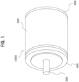
- FIG. 1 is an external perspective view of a rotating electric machine 1000 according to a first embodiment of the present invention.
- the rotating electric machine 1000 is a motor that rotates a rotor by making a direct-current magnetic field generated by a permanent magnet within the rotor and a rotating magnetic field emitted from a coil attract and repel each other.
- the rotating electric machine 1000 is a radial gap type motor used as a power source of a compressor.
- the rotating electric machine 1000 includes a housing 500 in a cylindrical shape, end brackets 400 in a disk shape which end brackets are provided at both ends of the housing 500, and a shaft 300 that projects from the center of one of the end brackets 400.
- FIG. 2 is a perspective view of a stator 100 of the rotating electric machine 1000 according to the present embodiment and a rotor 200 disposed within the stator 100. That is, FIG. 2 depicts an internal structure of the rotating electric machine 1000 with the housing 500, the end brackets 400, and the shaft 300 removed from FIG. 1 .
- the rotating electric machine 1000 includes the stator 100 in an annular shape and the rotor 200 disposed within the stator 100.
- the stator 100 includes a stator core 110 and a resin 160 in a cylindrical shape which resin is provided on both sides in an axial direction of the stator core 110.
- the periphery of the stator core 110 is fixed to the housing 500 depicted in FIG. 1 .
- the rotor 200 includes a rotor core 220 in a cylindrical shape and a plurality of permanent magnets 210 arranged circumferentially within the rotor core 220.
- the shaft 300 depicted in FIG. 1 is provided at the central axis of the rotor 200.
- the shaft 300 is rotatably fixed to the end bracket 400 via a bearing not depicted.
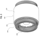
- FIG. 3 is a perspective view in which the resin 160 is removed from the stator 100 depicted in FIG. 2 .
- the stator 100 before resin molding processing includes the stator core 110, a coil 140, and bobbins 150.
- the coil 140 (for example, rectangular wire) is wound (for example, wave winding distributed winding) in the stator core 110 via the bobbins 150.
- FIG. 4 is a partial enlarged plan view of the stator core 110 according to the present embodiment.
- the stator core 110 includes a back yoke 130 in an annular shape and a plurality of teeth 120 projecting from an inner circumferential surface of the back yoke 130 to the rotor 200 side and arranged at equal intervals in a circumferential direction.
- the back yoke 130 is a cylindrical body obtained by laminating thin disks.
- the back yoke 130 has an inner wall 132 provided with a plurality of recessed portions 131 fitted with one ends of the teeth 120.
- the thin disks can be fabricated by, for example, stamping electromagnetic steel sheets by press working.
- the teeth 120 are columnar bodies obtained by laminating trapezoidal thin plates. An end portion 121 on a base side of a tooth 120 is fitted into a recessed portion 131 of the back yoke 130. The tooth 120 is thereby coupled to the back yoke 130.
- the trapezoidal thin plates can be fabricated by processing thin plates of an iron-base amorphous metal, for example.
- stator core 110 has a plurality of slots 111 each sandwiched by the inner wall 132 of the back yoke 130 and side walls 122 of two teeth 120 adjacent to each other in the circumferential direction of the stator core 110 and provided with an opening portion 112 on the rotor 200 side.
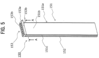
- FIG. 5 is an external perspective view of a bobbin 150 according to the present embodiment.
- the bobbin 150 is a part that insulates the coil 140 and the stator core 110 from each other.
- the bobbin 150 has the coil 140 inserted therein, and has a plurality of coil insertion holes 154 (to be described later).
- the bobbin 150 is fitted into a slot 111.
- Usable as a material for the bobbin 150 is a resin, for example, a liquid crystal polymer (LCP) that has a high strength, is suitable for small thickness molding, and has a high heat resistance.
- LCP liquid crystal polymer
- the bobbin 150 is provided with a tubular portion 151, a projecting portion 152, and a flange portion 153.
- FIG. 6 is a partial sectional perspective view of the stator 100 in which the bobbins 150 according to the present embodiment are fitted in the slots 111 of the stator core 110.
- the tubular portion 151 is a part fitted to the slot 111, and the tubular portion 151 has three side walls facing inner walls of the slot 111 and one side wall facing the opening portion 112 of the slot 111.
- the tubular portion 151 has a first side wall 151a along the inner wall 132 of the back yoke 130, two second side walls 151b along the side walls 122 of two teeth 120 adjacent to each other in the circumferential direction of the stator core 110, and a third side wall 151c facing the opening portion 112 (see FIGS.
- an air gap is formed between the opening portion 112 and the side wall that faces the opening portion 112 (third side wall 151c).
- the air gap forms an axial direction flow passage 161 (see FIG. 12 ) through which a liquid resin 162 flows in the axial direction of the stator 100 at a time of resin molding processing.
- the projecting portion 152 is a part that projects from the third side wall 151c to the rotor side (inward in the radial direction of the stator).
- the projecting portion 152 is a ridge that extends from one end to another end in the axial direction of the slot 111.
- the flange portion 153 is a part that is provided to one of end portions in the axial direction of the tubular portion 151, and covers a clearance formed between the slot 111 and the tubular portion 151 from an end surface side in the axial direction of the stator core 110 (which end surface will hereinafter be referred to as a core end surface).
- the flange portion 153 includes: a back yoke side part 153a that covers a part of an end surface in the axial direction of the back yoke 130 located radially outward of the slot 111; and two tooth side parts 153b that cover parts of respective end surfaces in the axial direction of the two teeth 120 sandwiching the slot 111 from the circumferential direction.
- the flange portion 153 is provided to one of the end portions in the axial direction of the tubular portion 151.
- flange portions 153 may be provided to both ends in the axial direction of the tubular portion 151.
- FIG. 7 is a sectional view taken in the direction of arrows along a line A-A of FIG. 5 .
- a length d2 for which the back yoke side part 153a extends from the tubular portion 151 in the radial direction of the stator core 110 is longer than a length d1 for which each of the two tooth side parts 153b extends from the tubular portion 151 in the circumferential direction of the stator core 110.
- the position of the bobbin 150 fitted in the slot 111 is determined in the axial direction of the stator core 110 by the abutting of the flange portion 153 against the stator core 110. Then, when the bobbin 150 is fitted into the slot 111, the clearance between the slot 111 and the tubular portion 151 is covered by the flange portion 153 from the outside in the axial direction of the stator core 110.
- FIG. 8 is an enlarged perspective view of an upper end of the bobbin 150 accordingto the present embodiment.
- the upper end of the bobbin 150 is provided with a plurality of coil insertion holes 154 (six coil insertion holes 154 in the present embodiment) for the insertion of the coil 140 (rectangular wire in the present embodiment).
- the coil insertion holes 154 reach a lower end of the bobbin 150, and thus penetrate the bobbin 150.
- the plurality of coil insertion holes 154 (six coil insertion holes 154 in the present embodiment) are provided within the tubular portion 151.
- the coil insertion holes 154 are holes having a substantially rectangular sectional shape.
- the outside in the axial direction of the back yoke side part 153a of the flange portion 153 forms a slope 155.
- the slope 155 has a rising gradient from the outside to the inside in the radial direction of the stator core 110 when the bobbin 150 is fitted in the slot 111.
- FIG. 9 is a sectional perspective view of the stator 100 having the coil 140 wound in the stator core 110 fitted with the bobbins 150 according to the present embodiment.
- the coil 140 has connecting portions 141 within the bobbins 150. That is, the coil 140 includes a first rectangular wire 142 and a second rectangular wire 143 (plurality of segment conductors), and the first rectangular wire 142 and the second rectangular wire 143 are connected to each other within the tubular portion 151 of a bobbin 150 fitted to the slot 111.
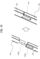
- FIG. 10 is an enlarged perspective view depicting the shapes of one ends of two segment conductors (the first rectangular wire 142 and the second rectangular wire 143) according to the present embodiment and the two segment conductors before being connected to each other (left side) and after being connected to each other (right side).
- the first rectangular wire 142 has a projecting portion 142a at one end thereof.
- the second rectangular wire 143 has a groove portion 143a at one end thereof.
- Each of the projecting portion 142a and the groove portion 143a has two faces substantially parallel with the axial direction of the conductors.
- the electric resistance of the connecting portion 141 can be reduced by connecting the two substantially parallel faces without a clearance.
- the first rectangular wire 142 and the second rectangular wire 143 are respectively inserted into the coil insertion hole 154 from opposite sides, and are coupled to each other within the tubular portion 151, such that the two faces of the projecting portion 142a and the two faces of the groove portion 143a, the faces being substantially parallel with the axial direction, are respectively superposed on each other.
- the resin 160 is a resin molded by mold processing (for example, transfer mold processing).
- a varnish molded by vacuum-pressurized impregnation processing for example, can also be used.
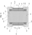
- FIG. 11 is a sectional view of a molding die 600 used for resin molding processing of the stator 100 according to the present embodiment and the stator 100 placed in the molding die 600.
- the molding die 600 includes a core die 610 in a cylindrical shape and a lower die 620 and an upper die 630 in a disk shape, the lower die 620 and the upper die 630 having a cylindrical portion.
- the core die 610 has a lower end thereof fitted in a circular hole 621 provided at the center of the lower die 620. The core die 610 is thus mounted on the lower die 620. Then, a hollow portion of the stator 100 is fitted onto the core die 610.
- a radially outward part of a lower end surface 134 in the axial direction of the back yoke 130 abuts against a distal end surface 623 of a cylindrical portion 622 projecting upward from an outer circumferential portion of the lower die 620.
- the coil end 144 at a lower portion of the stator 100 is thereby covered by the lower die 620.
- an upper end portion of the core die 610 is fitted into a circular hole 631 of the upper die 630.
- the upper die 630 is thus mounted on the core die 610.
- An end surface 633 of a cylindrical portion 632 projecting downward from an outer circumferential portion of the upper die 630 mounted on the core die 610 abuts against a radially outward part of an end surface 133 on an upper side in the axial direction of the back yoke 130.
- the coil end 144 at an upper portion of the stator 100 is thereby covered by the upper die 630.
- the stator 100 is fixed by being sandwiched between the lower die 620 and the upper die 630.
- a cavity (filling chamber) enclosed by the stator 100, the core die 610, and the lower die 620 or the upper die 630 is formed.
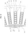
- an upper cavity 710 formed by the stator 100, the core die 610, and the upper die 630 and a lower cavity 720 formed by the stator 100, the core die 610, and the lower die 620 communicate with each other through axial direction flow passages 161 depicted in FIG. 12 .
- An axial direction flow passage 161 is enclosed by the third side wall 151c of the tubular portion 151 of the bobbin 150, the side walls 122 in the circumferential direction of the two teeth 120 adjacent to each other, and an outer peripheral wall of the core die 610. It is to be noted that the projecting portion 152 of the bobbin 150 abuts against the outer peripheral wall of the core die 610, and that the bobbin 150 is thereby inhibited from moving radially inward within the slot 111 and closing the axial direction flow passage 161.
- the liquid resin 162 (for example, a thermosetting resin such as unsaturated polyester) is heated to 100 to 150°C, and is injected into the upper cavity 710 under a pressure of a few MPa from injection ports (gates) 634 provided in the upper die 630.
- the liquid resin 162 injected into the upper cavity 710 flows into the lower cavity 720 via the axial direction flow passages 161, and is filled into the upper cavity 710, the lower cavity 720, and the axial direction flow passages 161.
- the liquid resin 162 is filled also into the clearance formed between the recessed portion 131 of the back yoke 130 and the end portions 121 of the teeth 120.
- stator 100 and the molding die 600 in which the upper cavity 710, the lower cavity 720, and the axial direction flow passages 161 are filled with the liquid resin 162 are heated to cure the liquid resin 162. After the liquid resin 162 is cured, the stator 100 is removed from the molding die 600, and the stator 100 depicted in FIG. 2 is formed.
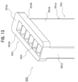
- FIG. 13 is an enlarged perspective view of an upper end of a bobbin according to a comparative example. As depicted in FIG. 13 , a third side wall 951c of a tubular portion 951 does not have the projecting portion 152, and a back yoke side part 953a of a flange portion 953 does not have the slope 155.
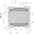
- FIG. 14 is a sectional view of a molding die 600 used for resin molding processing of a stator 900 according to the comparative example of the present invention and the stator 900 placed in the molding die 600.
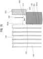
- FIG. 15 is an enlarged view of an A part in FIG. 14 .
- FIG. 16 is a sectional view of the stator according to the comparative example of the present invention, the sectional view schematically depicting a pressure Pr applied to the connecting portion 141 of the coil 140 when the liquid resin 162 intrudes between the back yoke 130 and a bobbin 950 of the stator 900.
- the stator 900 according to the comparative example as in the stator 100 according to the first embodiment of the present invention, the first rectangular wire 142 and the second rectangular wire. 143 are connected to each other within the slot 111, and the connecting portion 141 is included within the tubular portion 951 of the bobbin 950. Moreover, as depicted in FIG. 14 , as with the stator 100 according to the first embodiment of the present invention, the stator 900 according to the comparative example is fixed to the molding die 600, and the liquid resin 162 is injected from the gates 634 of the upper die 630.
- the bobbin 950 does not have the projecting portion 152 on the third side wall 951c of the tubular portion 951, as depicted in FIG. 13 . Therefore, the securing of the axial direction flow passage 161 through the abutment of the projecting portion 152 against the outer peripheral wall of the core die 610 as in FIG. 12 is not realized.
- the tubular portion 951 may move in the direction of the core die 610 depicted in FIG. 14 .
- a clearance may be formed between a first side wall 951a and the inner wall 132 of the back yoke 130.
- the liquid resin 162 is sufficiently heated, and is injected in a state of low viscosity. Therefore, the liquid resin 162 may intrude into a clearance between the first side wall 951a of the tubular portion 951 of the bobbin 950 and the inner wall 132 of the back yoke 130 from a clearance between the back yoke side part 953a of the flange portion 953 and the back yoke 130.
- the annular coil ends 144 specific to distributed winding are formed, and are restricted with regard to deformation in the radial direction. Therefore, when the liquid resin 162 intrudes between the tubular portion 951 and the back yoke 130, a radially inward pressing force Pr is applied only to the coil 140 within the slot 111. Consequently, when the connecting portion 141 is separated, or a contact area is decreased, an increase in contact resistance is invited, and there is a fear of causing local heat generation due to an increase in Joule loss and faults such as a melting or a loss of bobbins, conduction between the coil 140 and the stator core 110, and a ground fault.
- the rotating electric machine 1000 according to the present invention is subjected to resin molding processing such that the stator core 110, the bobbins 150, and the coil 140 are integrated with each other by the resin 160 in order to suppress a weakening of electric connection of the connecting portion 141 of the coil 140.
- the core die 610 is placed in the hollow portion of the stator 100, and the upper die 630 and the lower die 620 covering the coil ends 144 sandwich the stator 100 from both sides in the axial direction.
- the liquid resin 162 is injected from the gates 634 into the cavity (the filling chamber) formed between the core die 610, the upper die 630 or the lower die 620, and the stator 100.
- the electric connection of the connecting portion 141 of the coil 140 may be weakened.
- the rotating electric machine 1000 has the projecting portion 152 provided to the third side wall 151c of the bobbin 150.
- the projecting portion 152 abuts against the outer peripheral wall of the core die 610 placed in a hollow portion of the stator core 110 at the time of the resin molding processing, and prevents the bobbin 150 from moving toward the opening portion 112 (see FIG. 4 ) of the slot 111. It is therefore possible to prevent the formation of a clearance between the stator core 110 and the bobbin 150 through which clearance the liquid resin 162 intrudes easily.
- the intrusion of the liquid resin 162 between the stator core 110 and the bobbin 150 at the time of the resin molding processing can be suppressed, so that a weakening of the electric connection of the connecting portion 141 due to a deformation of the coil 140 can be suppressed.
- the projecting portion 152 abuts against the core die 610, and thereby the axial direction flow passage 161 of the liquid resin 162 is formed on the periphery of the projecting portion 152 within the slot 111. Then, the liquid resin 162 flowing into the axial direction flow passage 161 during the resin molding processing presses the tubular portion 151 of the bobbin 150 against the inner wall 132 on the outside diameter side of the slot 111.
- the intrusion of the liquid resin 162 between the stator core 110 and the bobbin 150 can be suppressed, so that a weakening of the electric connection of the connecting portion 141 due to a deformation of the coil 140 can be suppressed.
- the projecting portion 152 is a ridge that extends from one end to the other end in the axial direction of the slot 111. Therefore, the tubular portion 151 can be pressed against the inner wall 132 on the outside diameter side of the slot 111 over an extent from one end to the other end in the axial direction of the slot 111. Hence, the intrusion of the liquid resin 162 between the stator core 110 and the bobbin 150 can be further suppressed, so that a weakening of the electric connection of the connecting portion 141 due to a deformation of the coil 140 can be further suppressed.
- the length d2 for which the back yoke side part 153a according to the present embodiment extends from the tubular portion 151 in the radial direction of the stator core 110 is longer than the length d1 for which each of the two tooth side parts 153b extends from the tubular portion 151 in the circumferential direction of the stator core 110. It is therefore possible. to suppress the intrusion of the liquid resin 162 between the inner wall 132 of the back yoke 130 and the first side wall 151a of the bobbin 150 from between the side walls 122 of the two teeth 120 adjacent to each other in the circumferential direction and the two second side walls 151b of the bobbin 150.
- the bobbin 150 is prevented from moving inward in the radial direction within the slot 111 and forming a clearance between the back yoke side part (flange portion) and the stator core, and thereby the intrusion of the resin between the stator core and the bobbin can be suppressed, so that a weakening of the electric connection of the connecting portion due to a deformation of the coil can be suppressed.
- the face 155 on the outside in the axial direction of the back yoke side part 153a provided to the flange portion 153 of the bobbin 150 according to the present embodiment is a slope with a rising gradient from the outside to the inside in the radial direction of the stator core 110. Therefore, as depicted in FIG. 17 , a pressure Pr with which the liquid resin 162 presses the back yoke side part 153a of the flange portion 153 from the outside in the radial direction can be decomposed into a pressure Pr' perpendicular to the slope 155 and a pressure Pr" horizontal to the slope 155.
- the pressure Pr' perpendicular to the slope 155 can be decomposed into a pressure Pr'1 perpendicular to the end surface 133 of the back yoke 130 and a pressure Pr"2 (not depicted) horizontal to the end surface 133.
- an intra-slot connection system is adopted in which the coil 140 according to the present embodiment includes a plurality of segment conductors, and the plurality of segment conductors are connected to each other within the tubular portion 151 of the bobbin 150 fitted in the slot 111. Therefore, as compared with a coil end connection system in which the coil is connected at the coil ends of the coil by welding, a need for bending processing and welding at the coil ends is obviated. It is therefore possible to achieve higher production and miniaturization of the rotating electric machine.
- the plurality of segment conductors of the coil 140 include the first rectangular wire 142 having the projecting portion 142a at one end thereof, the second rectangular wire 143 having the groove portion 143a at one end thereof, and the connecting portion 141 in which the projecting portion 142a is fitted to the groove portion 143a. Therefore, the projecting portion 142a and the groove portion 143a are fitted to each other by merely pushing the projecting portion 142a into the groove portion 143a, and the projecting portion 142a and the groove portion 143a (that is, the first rectangular wire 142 and the second rectangular wire 143) can be easily connected to each other.
- stator core 110 includes: a recessed portion 131 provided to the inner circumferential surface of the back yoke 130 in a cylindrical shape and extending in the axial direction of the back yoke 130; and a tooth 120 having the end portion 121 fitted in the recessed portion 131.
- the liquid resin 162 (resin 160) is filled into a clearance in the radial direction which clearance is formed between the recessed portion 131 and the end portion 121 of the tooth 120.
- the tooth 120 is pressed inward in the radial direction, so that a clearance in the circumferential direction which clearance is formed between the recessed portion 131 of the back yoke 130 and the end portion 121 of the tooth 120 fitted in the recessed portion 131 can be made smaller than a clearance therebetween in the radial direction. Therefore, a magnetic flux flowing within the tooth 120 from another end 123 of the tooth 120 to the end portion 121 flows from the end portion 121 of the tooth 120 to the recessed portion 131 of the back yoke 130 in the circumferential direction.
- the tooth 120 in the present embodiment is a trapezoidal column that can be formed by an amorphous metal, the iron loss can be further reduced.
- the rotating electric machine 1000 according to the present embodiment can be used as a power source of a compressor.
- the compressor using the low-loss rotating electric machine 1000 according to the present embodiment as a power source thereof can achieve an energy saving.
- FIG. 18 is an enlarged perspective view of an upper end of the bobbin 2150 according to the second embodiment of the present invention.
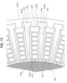
- FIG. 19 is a partial plan view depicting a state in which bobbins 2150 according to the second embodiment of the present invention are fitted to the slots 111 of the stator core 110.
- the bobbin 2150 according to the present embodiment is different from the bobbin 150 according to the first embodiment in the following respects. Specifically, a face 2156 on the outside in the axial direction of each of two tooth side parts 2153b of a flange portion 2153 of the bobbin 2150 is a slope with a rising gradient from an end surface in the axial direction of the teeth 120 to the slot 111.
- FIG. 19 is a partial plan view of the stator 100 in which the bobbins 2150 according to the present embodiment are fitted in the slots 111 of the stator core 110. Because the face 2156 on the outside in the axial direction of each of the tooth side parts 2153b (see FIG. 18 ) of the flange portion 2153 is a slope, the width of radial direction flow passages 163 on the teeth 120 in the circumferential direction of a stator 2100 is increased on an upper side, and the flow passage sectional area of the radial direction flow passages 163 is increased on the upper side.
- the face 2156 on the outside in the axial direction of each of the tooth side parts 2153b of the flange portion 2153 is a slope, the width of the radial direction flow passages 163 on the teeth 120 in the circumferential direction of the stator 2100 is increased on the upper side, and the flow passage cross-sectional area of the radial direction flow passages 163 is increased on the upper side.
- a pressure loss (friction loss) when the liquid resin 162 flows through the radial direction flow passages 163 can be reduced, so that the liquid resin 162 flows to the axial direction flow passage 161 easily. It is thereby possible to suppress a decrease in the strength of the resin 160 due to a molding defect such as voids (air bubbles) or a decrease in density.
- the liquid resin 162 filled into the upper cavity 710 presses the slopes 2156 of the two tooth side parts 2153b of the flange portion 2153 of the bobbin 2150.
- Forces perpendicular to the slopes 2156 are generated at the tooth side parts 2153b having the slopes 2156 pressed by the liquid resin 162, so that surfaces of the tooth side parts 2153b which surfaces face the end surfaces in the axial direction of the teeth 120 are pressed against the end surfaces in the axial direction of the teeth 120. Therefore, a movement of the bobbin 2150 in the radial direction is suppressed. It is thereby possible to suppress the formation of a clearance between the tubular portion 151 of the bobbin 2150 and the inner wall of the slot 111 of the stator core 110. Hence, the intrusion of the liquid resin 162 between the stator core 110 and the bobbin 2150 can be suppressed, so that a weakening of the electric connection of the connecting portion due to a deformation of the coil 140 can be suppressed.
- FIG. 20 is an external perspective view of a bobbin 3150 according to a third embodiment of the present invention.
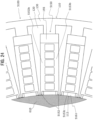
- FIG. 21 is a partial plan view of a stator 3100 in which bobbins 3150 according to the third embodiment of the present invention are fitted in the slots 111 of the stator core 110.
- the bobbin 3150 according to the present embodiment is different from the bobbin 150 according to the first embodiment in terms of projecting portions 3152.
- the projecting portion 152 according to the first embodiment is one ridge that projects from the third side wall 151c facing the opening portion 112 of the tubular portion 151, and extends from one end to another end in the axial direction of the slot 111.
- the projecting portions 3152 according to the present embodiment are two ridges that project from the third side wall 151c and extend along the side walls 122 (see FIG. 4 ) of the two teeth 120 sandwiching the slot 111.
- the projecting portions 3152 of the bobbin 3150 according to the present embodiment are two ridges that extend along the side surfaces of the two teeth 120 sandwiching the slot 111. Therefore, an axial direction flow passage 3161 is one flow passage having a larger cross-sectional area than the axial direction flow passage 161 according to the first embodiment which flow passage is divided into two by the projecting portion 152. Therefore, the liquid resin 162 flows through the axial direction flow passage 3161 easily. It is consequently possible to suppress a decrease in the strength of the resin 160 due to a molding defect such as voids (air bubbles) or a decrease in density.
- FIG. 22 is an enlarged perspective view of an upper end of a bobbin 4150 according to a fourth embodiment of the present invention.
- the bobbin 4150 according to the present embodiment is different from the bobbin 150 according to the first embodiment in terms of the shape and position of a projecting portion 4152.
- the projecting portion 152 is one ridge that projects from the third side wall 151c facing the opening portion 112 of the tubular portion 151, and extends from one end to another end in the axial direction of the slot 111.
- the projecting portion 4152 according to the present embodiment is a projection provided to an external wall 4151d on the opening portion 112 side in a flange portion 4153.
- the projecting portion 4152 is a projection provided to the external wall 4151d on the opening portion 112 side in the flange portion 4153. Therefore, an axial direction flow passage 4161 is not divided into two in the axial direction by the projecting portion 152 unlike the axial direction flow passage 161 according to the first embodiment, but includes one flow passage having a large cross-sectional area. Hence, a pressure loss (friction loss) caused by the flow passage can be reduced, so that the liquid resin 162 flows through the axial direction flow passage 3161 easily. It is thereby possible to suppress a decrease in the strength of the resin 160 due to a molding defect such as voids (air bubbles) or a decrease in density.
- the projecting portion 4152 abuts against the core die 610.
- the bobbin 4150 cannot move inward in the radial direction.
- the liquid resin 162 intrudes into the axial direction flow passage 161, so that the bobbin 4150 is pressed outward in the radial direction.
- the intrusion of the liquid resin 162 between the stator core 110 and the bobbin 4150 can be suppressed, so that a weakening of the electric connection of the connecting portion 141 due to a deformation of the coil 140 can be suppressed.
- FIG. 23 is an enlarged perspective view of an upper end of a bobbin 5150 according to a fifth embodiment of the present invention.
- FIG. 24 is a partial plan view of a stator 5100 in which bobbins 5150 according to the fifth embodiment of the present invention are fitted in the slots 111 of the stator core 110.
- the bobbin 5150 according to the present embodiment is different from the bobbin 4150 according to the fourth embodiment in terms of positions at which projecting portions 5152 are provided and the number thereof.
- one projecting portion 4152 is provided to the external wall 4151d on the opening portion 112 side in the flange portion 4153.
- the projecting portions 5152 are provided to external walls 5153d on the opening portion 112 side in two respective.tooth side parts 5153b of a flange portion 5153. That is, one projecting portion 4152 according to the fourth embodiment is provided to the external wall 4151d of the flange portion 4153.
- a total of two projecting portions 5152 according to the fifth embodiment are provided, one to each of the external walls 5153d of the two tooth side parts 5153b of the flange portion 5153.
- the projecting portions 5152 may be two ridges that are located at both ends of the flange portion 5153 in the circumferential direction of the stator core 110, and project radially inward of the stator core 110.
- the projecting portions 5152 according to the present embodiment are provided to the external walls 5153d on the inside in the radial direction of the stator core 110 in the two respective tooth side parts 5153b of the flange portion 5153. Therefore, base portions are thick, thus enabling rigidity to be increased, and the base portions can be molded easily.
- the projecting portions 5152 are provided to the two tooth side parts 5153b that cover parts of the end surfaces in the axial direction of the two respective teeth 120 sandwiching the slot 111 from the circumferential direction. Therefore, the inlet of an axial direction flow passage 5161 is not divided into two unlike the projecting portion 4152 according to the fourth embodiment.
- the projecting portions 5152 are two ridges that are located at both ends of the flange portion 5153 in the circumferential direction of the stator core 110, and project radially inward of the stator core 110, the inlet of the axial direction flow passage 5161 can be opened wide, as depicted in FIG. 24 . Therefore, the liquid resin 162 flows into the axial direction flow passage 5161 easily.
- a pressure loss (friction loss) caused by the flow passage can be further reduced, so that the liquid resin 162 flows through the axial direction flow passage 5161 easily. It is thereby possible to suppress a decrease in the strength of the resin 160 due to a molding defect such as voids (air bubbles) or a decrease in density.
- a molding pressure for filling the cavities 710 and 720 with the liquid resin 162 at a predetermined density and therefore suppress a deformation of the coil 140 or the like due to the pressing force of the liquid resin 162. Consequently, a weakening of the electric connection of the connecting portion due to a deformation of the coil can be suppressed. Further, because the shape of the bobbin 4150 can be simplified, moldability can be improved.
- the projecting portions 5152 abut against the core die 610.
- the bobbin 5150 cannot move inward in the radial direction.
- the liquid resin 162 intrudes into the axial direction flow passage 5161, so that the bobbin 5150 is pressed outward in the radial direction.
- the intrusion of the liquid resin 162 between the stator core 110 and the bobbin 5150 can be suppressed, so that a weakening of the electric connection of the connecting portion 141 due to a deformation of the coil 140 can be suppressed.
- FIG. 25 is an external perspective view of a bobbin 6150 according to the present embodiment.
- FIG. 26 is a sectional view depicting a state in which a stator 6100 using bobbins 6150 according to the sixth embodiment of the present invention is placed in the molding die 600.
- FIG. 27 is an enlarged view of an A part in FIG. 30.
- FIG. 28 is a partial plan view of the stator 6100 according to the present embodiment.
- the bobbin 6150 according to the present embodiment is different from the bobbin 150 according to the first embodiment in terms of the shape of a back yoke side part 6153a of a flange portion 6153.
- the back yoke side part 6153a does not have the slope 155 on the outside in the axial direction, but an outer surface in the axial direction of the flange portion 6153 extends.
- an outer end surface 6155 on the outside in the radial direction of the stator core 110 in the back yoke side part 6153a is located more to the outside of the stator core 110 in the radial direction than an outermost inner circumferential wall 6341 of a gate 634 in the radial direction of the stator core 110.
- the outer end surface 6155 is located more outward in the radial direction of the stator core 110 than a gate mark 164 formed on the surface of the resin 160.
- the gate mark 164 may be formed on, for example, a side surface as an inclined surface of the resin 160.
- the outer end surface 6155 can be brought into close contact with an inner circumferential wall 6321 of the upper die 630. In this case, the outer end surface 6155 is exposed from the resin 160.
- the position of a resin injection port (gate 634) of a mold (upper die 630) used at a time of the resin molding processing appears as a gate mark on the surface of the resin 160.
- the end surface on the outside in the radial direction of the stator core 110 in the back yoke side part 6153a (which end surface will hereinafter be referred to as an outer end surface) 6155 is located more outward in the radial direction of the stator core than the gate mark as in the present embodiment
- the liquid resin 162 at the time of the resin molding processing is injected in the direction of the flange portion 6153 from a position more inward in the radial direction than the outer end surface 6155 of the back yoke side part 6153a.
- the liquid resin.162 presses a surface 6156 on the outside in the axial direction as compared with the outer end surface 6155 of the back yoke side part 6153a.
- the back yoke side part (flange portion) can be easily pressed toward the stator core. Consequently, a clearance is prevented from being formed between the back yoke side part (flange portion) and the stator core.
- the intrusion of the resin between the stator core and the bobbin can be suppressed, so that a weakening of the electric connection of the connecting portion 141 due to a deformation of the coil 140 can be suppressed.
- the outer end surface 6155 is not covered by the resin 160, but is exposed from the resin 160.
- the outer end surface 6155 is not pressed by the liquid resin 162 injected from the gate 634 of the upper die 630.
- the present invention is not limited to the foregoing embodiments, but includes various modifications.
- the foregoing embodiments are described in detail to describe the present invention in an easily understandable manner, and are not necessarily limited to embodiments including all of the described configurations.
- a part of a configuration of a certain embodiment can be replaced with a configuration of another embodiment, and a configuration of another embodiment can be added to a configuration of a certain embodiment.
- addition of another configuration, deletion, or substitution with another configuration is also possible.
- an embodiment of the present invention may be the following mode.
- the rotating electric machine 1000 is a wave winding distributed winding radial gap type motor used as a power source of a compressor.
- the rotating electric machine 1000 may be applied as a generator rather than a motor.
- the wave winding distributed winding but another winding method may be adopted.
- the rotating electric machine 1000 may be used as a power source for an industrial machine such as an industrial robot, a press machine, or a hydraulic machine other than a compressor as well as an automobile, a household electric appliance, or the like.
- a slot combination of the number of poles and the number of slots, the materials of the stator core and the resin, the shapes of the projecting portions and the flange portions of the bobbins, and the like are not limited to the foregoing embodiments.
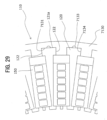
- a second recessed portion 7133 may be provided to the bottom surface of a first recessed portion 7131 of a back yoke 7130 which bottom surface faces a radially outward surface 121a of a tooth 120. Consequently, with the second recessed portion 7133 as a starting point, the liquid resin 162 is filled between the radially outward surface 121a of the teeth 120 and the bottom surface of the first recessed portion 7131 of the back yoke 7130. The liquid resin 162 pressurizes the tooth 120 inward in the radial direction.
- the side walls 122 of the tooth 120 in the circumferential direction of a stator core 7110 are pressed against circumferential direction side walls 7134 of the first recessed portion 7131 of the back yoke 7130.
- the tooth 120 is further pressed inward in the radial direction, so that a clearance in the circumferential direction which clearance is formed between the recessed portion of the back yoke and one end of the tooth fitted in the recessed portion can be made smaller than a clearance therebetween in the radial direction. Therefore, a magnetic flux flowing within the tooth from another end of the tooth to the one end further flows from the one end of the tooth to the recessed portion of the back yoke in the circumferential direction.
- a stator core is divided into a back yoke and a plurality of teeth
- a stator core may include a back yoke and teeth integral with each other.
- the teeth are formed as a trapezoidal column
- a widening portion may be provided to distal ends of the teeth, and thereby the slots are semi-closed.
- the resin is preferably a thermosetting resin
- the resin may be a resin for pressure molding.
- the resin may be a thermoplastic resin.
- a resin exhibiting a small curing shrinkage and having a linear expansion coefficient close to that of an iron core is preferably used in order to reduce an effect exerted on the connecting portions of the coil.
Landscapes
- Engineering & Computer Science (AREA)
- Power Engineering (AREA)
- Manufacturing & Machinery (AREA)
- Insulation, Fastening Of Motor, Generator Windings (AREA)
Abstract
Description
- The present invention relates to a rotating electric machine and an industrial machine.
- Demands for energy saving have been rising against the backdrop of global warming and the exhaustion of fossil fuels. Energy saving has been promoted also in rotating electric machines used in many fields of industrial machines, automobiles, household electric appliances, and the like, and a reduction in loss has been an important development challenge.
- Suppressing a copper loss by reducing the resistance value of a coil is effective means for a reduction in loss. Accordingly, a rotating electric machine has been developed which suppresses the copper loss by using a rectangular wire, which can reduce the resistance value by increasing the cross-sectional area of the coil and increasing a ratio of the coil to the cross-sectional area of a slot of a stator core (space factor).
- The rotating electric machine using this rectangular wire presents a problem in that distributed winding of the coil causes coil ends to be raised. However, a rotating electric machine has been disclosed in which the coil ends are lowered by connecting rectangular wires divided into predetermined segments to each other on the inside and outside of the slots of the stator core (for example, Patent Document 1).
- Patent Document 1:
PCT Patent Publication No. WO2020/017133 - However, the electric connection of a part in which the rectangular wires are connected to each other (connecting portion) may be weakened due to a Lorentz force, a vibration, a temperature change, or the like. Accordingly, the inventor(s) has conceived suppressing a weakening of the electric connection of the connecting portion by integrating the stator core and the coil with each other by a resin, and has fabricated a prototype. Then, it has been found that at a time of resin molding processing, the resin may weaken the electric connection of the connecting portion by intruding between the stator core and bobbins, pressing the bobbins, and deforming the coil within the bobbins.
- It is an object of the present invention to provide a rotating electric machine that can suppress the intrusion of a resin between a stator core and bobbins at a time of resin molding processing.
- In order to achieve the above object, there is provided a rotating electric machine including: a rotor; a stator core having a slot provided with an opening portion on a side of the rotor; a bobbin that is fitted into the slot, and into which a coil is inserted; a projecting portion disposed on a side of the opening portion in the bobbin; and a resin that fixes the stator core, the coil, and the bobbin to each other.
- According to the present invention, the intrusion of the resin between the stator core and the bobbin at a time of resin molding processing can be suppressed, so that a weakening of the electric connection of the connecting portion due to a deformation of the coil can be suppressed. Problems, configurations, and effects other than those described above will be made apparent by the following description of embodiments.
-
-
FIG. 1 is an external perspective view of a rotating electric machine according to a first embodiment of the present invention. -
FIG. 2 is a perspective view of a stator according to the first embodiment of the present invention and a rotor disposed within the stator. -
FIG. 3 is a perspective view in which a resin is removed from the stator depicted inFIG. 2 . -
FIG. 4 is a partial enlarged plan view of a stator core according to the first embodiment of the present invention. -
FIG. 5 is an external perspective view of a bobbin according to the first embodiment of the present invention. -
FIG. 6 is a partial sectional perspective view of the stator in which bobbins according to the first embodiment of the present invention are fitted in slots of the stator core. -
FIG. 7 is a sectional view taken in the direction of arrows along a line A-A ofFIG. 5 . -
FIG. 8 is an enlarged perspective view of an upper end of the bobbin according to the first embodiment of the present invention. -
FIG. 9 is a sectional perspective view of the stator in which the bobbins according to the first embodiment of the present invention are fitted in the stator core, and a coil is wound in the stator core. -
FIG. 10 is an enlarged perspective view depicting the shapes of one ends of two segment conductors according to the first embodiment of the present invention and the two segment conductors before being connected to each other (left side) and after being connected to each other (right side). -
FIG. 11 is a sectional view of a molding die used for resin molding processing of the stator according to the first embodiment of the present invention and the stator placed in the molding die. -
FIG. 12 is a fragmentary sectional view taken in the direction of arrows along a line A-A ofFIG. 11 . -
FIG. 13 is an enlarged perspective view of an upper end of a bobbin according to a comparative example of the present invention. -
FIG. 14 is a sectional view of a molding die used for resin molding processing of a stator according to the comparative example of the present invention and the stator placed in the molding die. -
FIG. 15 is an enlarged view of an A part inFIG. 16 . -
FIG. 16 is a sectional view of the stator according to the comparative example of the present invention, the sectional view schematically depicting a pressure applied to the connecting portion of the coil when the liquid resin intrudes between a back yoke and a bobbin of the stator. -
FIG. 17 is an enlarged view of a B part inFIG. 11 . -
FIG. 18 is an enlarged perspective view of an upper end of a bobbin according to a second embodiment of the present invention. -
FIG. 19 is a partial plan view of a stator in which bobbins according to the second embodiment of the present invention are fitted in the slots of the stator core. -
FIG. 20 is an external perspective view of a bobbin according to a third embodiment of the present invention. -
FIG. 21 is a partial plan view of stator in which bobbins according to the third embodiment of the present invention are fitted in the slots of the stator core. -
FIG. 22 is an enlarged perspective view of an upper end of a bobbin according to a fourth embodiment of the present invention. -
FIG. 23 is an enlarged perspective view of an upper end of a bobbin according to a fifth embodiment of the present invention. -
FIG. 24 is a partial plan view of a stator in which bobbins according to the fifth embodiment of the present invention are fitted in the slots of the stator core. -
FIG. 25 is an external perspective view of a bobbin according to a sixth embodiment of the present invention. -
FIG. 26 is a sectional view depicting a state in which a stator using bobbins according to the sixth embodiment of the present invention is placed in the molding die. -
FIG. 27 is an enlarged view of an A part inFIG. 26 . -
FIG. 28 is a partial plan view of the stator according to the sixth embodiment of the present invention. -
FIG. 29 is a partial enlarged plan view of a stator in which bobbins are fitted in a stator core according to another embodiment of the present invention. - In the following, rotating
electric machines 1000 according to a first to a sixth embodiment of the present invention will be described with reference to the drawings. Incidentally, in each figure, identical reference numerals denote identical parts. -
FIG. 1 is an external perspective view of a rotatingelectric machine 1000 according to a first embodiment of the present invention. The rotatingelectric machine 1000 is a motor that rotates a rotor by making a direct-current magnetic field generated by a permanent magnet within the rotor and a rotating magnetic field emitted from a coil attract and repel each other. For example, the rotatingelectric machine 1000 is a radial gap type motor used as a power source of a compressor. - The rotating
electric machine 1000 includes ahousing 500 in a cylindrical shape,end brackets 400 in a disk shape which end brackets are provided at both ends of thehousing 500, and ashaft 300 that projects from the center of one of theend brackets 400. -
FIG. 2 is a perspective view of astator 100 of the rotatingelectric machine 1000 according to the present embodiment and arotor 200 disposed within thestator 100. That is,FIG. 2 depicts an internal structure of the rotatingelectric machine 1000 with thehousing 500, theend brackets 400, and theshaft 300 removed fromFIG. 1 . The rotatingelectric machine 1000 includes thestator 100 in an annular shape and therotor 200 disposed within thestator 100. - As depicted in
FIG. 2 , thestator 100 includes astator core 110 and aresin 160 in a cylindrical shape which resin is provided on both sides in an axial direction of thestator core 110. The periphery of thestator core 110 is fixed to thehousing 500 depicted inFIG. 1 . - The
rotor 200 includes arotor core 220 in a cylindrical shape and a plurality ofpermanent magnets 210 arranged circumferentially within therotor core 220. Theshaft 300 depicted inFIG. 1 is provided at the central axis of therotor 200. Theshaft 300 is rotatably fixed to theend bracket 400 via a bearing not depicted. -
FIG. 3 is a perspective view in which theresin 160 is removed from thestator 100 depicted inFIG. 2 . As depicted inFIG. 3 , thestator 100 before resin molding processing includes thestator core 110, acoil 140, andbobbins 150. The coil 140 (for example, rectangular wire) is wound (for example, wave winding distributed winding) in thestator core 110 via thebobbins 150. -
FIG. 4 is a partial enlarged plan view of thestator core 110 according to the present embodiment. Thestator core 110 includes aback yoke 130 in an annular shape and a plurality ofteeth 120 projecting from an inner circumferential surface of theback yoke 130 to therotor 200 side and arranged at equal intervals in a circumferential direction. - The
back yoke 130 is a cylindrical body obtained by laminating thin disks. Theback yoke 130 has aninner wall 132 provided with a plurality of recessedportions 131 fitted with one ends of theteeth 120. The thin disks can be fabricated by, for example, stamping electromagnetic steel sheets by press working. - The
teeth 120 are columnar bodies obtained by laminating trapezoidal thin plates. Anend portion 121 on a base side of atooth 120 is fitted into a recessedportion 131 of theback yoke 130. Thetooth 120 is thereby coupled to theback yoke 130. The trapezoidal thin plates can be fabricated by processing thin plates of an iron-base amorphous metal, for example. - In addition, the
stator core 110 has a plurality ofslots 111 each sandwiched by theinner wall 132 of theback yoke 130 andside walls 122 of twoteeth 120 adjacent to each other in the circumferential direction of thestator core 110 and provided with anopening portion 112 on therotor 200 side. -
FIG. 5 is an external perspective view of abobbin 150 according to the present embodiment. Thebobbin 150 is a part that insulates thecoil 140 and thestator core 110 from each other. Thebobbin 150 has thecoil 140 inserted therein, and has a plurality of coil insertion holes 154 (to be described later). Thebobbin 150 is fitted into aslot 111. Usable as a material for thebobbin 150 is a resin, for example, a liquid crystal polymer (LCP) that has a high strength, is suitable for small thickness molding, and has a high heat resistance. As depicted inFIG. 5 , thebobbin 150 is provided with atubular portion 151, a projectingportion 152, and aflange portion 153. -
FIG. 6 is a partial sectional perspective view of thestator 100 in which thebobbins 150 according to the present embodiment are fitted in theslots 111 of thestator core 110. As depicted inFIG. 6 , thetubular portion 151 is a part fitted to theslot 111, and thetubular portion 151 has three side walls facing inner walls of theslot 111 and one side wall facing theopening portion 112 of theslot 111. Specifically, thetubular portion 151 has afirst side wall 151a along theinner wall 132 of theback yoke 130, twosecond side walls 151b along theside walls 122 of twoteeth 120 adjacent to each other in the circumferential direction of thestator core 110, and athird side wall 151c facing the opening portion 112 (seeFIGS. 4 and5 ). Incidentally, an air gap is formed between the openingportion 112 and the side wall that faces the opening portion 112 (third side wall 151c). The air gap forms an axial direction flow passage 161 (seeFIG. 12 ) through which aliquid resin 162 flows in the axial direction of thestator 100 at a time of resin molding processing. - The projecting
portion 152 is a part that projects from thethird side wall 151c to the rotor side (inward in the radial direction of the stator). In the present embodiment, the projectingportion 152 is a ridge that extends from one end to another end in the axial direction of theslot 111. - In addition, the
flange portion 153 is a part that is provided to one of end portions in the axial direction of thetubular portion 151, and covers a clearance formed between theslot 111 and thetubular portion 151 from an end surface side in the axial direction of the stator core 110 (which end surface will hereinafter be referred to as a core end surface). Specifically, theflange portion 153 includes: a backyoke side part 153a that covers a part of an end surface in the axial direction of theback yoke 130 located radially outward of theslot 111; and twotooth side parts 153b that cover parts of respective end surfaces in the axial direction of the twoteeth 120 sandwiching theslot 111 from the circumferential direction. Incidentally, in the present embodiment., theflange portion 153 is provided to one of the end portions in the axial direction of thetubular portion 151. However,flange portions 153 may be provided to both ends in the axial direction of thetubular portion 151. -
FIG. 7 is a sectional view taken in the direction of arrows along a line A-A ofFIG. 5 . As depicted inFIG. 7 , a length d2 for which the backyoke side part 153a extends from thetubular portion 151 in the radial direction of thestator core 110 is longer than a length d1 for which each of the twotooth side parts 153b extends from thetubular portion 151 in the circumferential direction of thestator core 110. - In addition, as depicted in
FIG. 6 , the position of thebobbin 150 fitted in theslot 111 is determined in the axial direction of thestator core 110 by the abutting of theflange portion 153 against thestator core 110. Then, when thebobbin 150 is fitted into theslot 111, the clearance between theslot 111 and thetubular portion 151 is covered by theflange portion 153 from the outside in the axial direction of thestator core 110. -
FIG. 8 is an enlarged perspective view of an upper end of thebobbin 150 accordingto the present embodiment. As depicted inFIG. 8 , the upper end of thebobbin 150 is provided with a plurality of coil insertion holes 154 (six coil insertion holes 154 in the present embodiment) for the insertion of the coil 140 (rectangular wire in the present embodiment). - The coil insertion holes 154 reach a lower end of the
bobbin 150, and thus penetrate thebobbin 150. Hence, the plurality of coil insertion holes 154 (six coil insertion holes 154 in the present embodiment) are provided within thetubular portion 151. Incidentally, because a rectangular wire is used as thecoil 140 in the present embodiment, the coil insertion holes 154 are holes having a substantially rectangular sectional shape. - In addition, as depicted in
FIG. 8 , the outside in the axial direction of the backyoke side part 153a of theflange portion 153 forms aslope 155. Theslope 155 has a rising gradient from the outside to the inside in the radial direction of thestator core 110 when thebobbin 150 is fitted in theslot 111. -
FIG. 9 is a sectional perspective view of thestator 100 having thecoil 140 wound in thestator core 110 fitted with thebobbins 150 according to the present embodiment. As depicted inFIG. 9 , thecoil 140 has connectingportions 141 within thebobbins 150. That is, thecoil 140 includes a firstrectangular wire 142 and a second rectangular wire 143 (plurality of segment conductors), and the firstrectangular wire 142 and the secondrectangular wire 143 are connected to each other within thetubular portion 151 of abobbin 150 fitted to theslot 111. -
FIG. 10 is an enlarged perspective view depicting the shapes of one ends of two segment conductors (the firstrectangular wire 142 and the second rectangular wire 143) according to the present embodiment and the two segment conductors before being connected to each other (left side) and after being connected to each other (right side). - The first
rectangular wire 142 has a projectingportion 142a at one end thereof. The secondrectangular wire 143 has agroove portion 143a at one end thereof. Each of the projectingportion 142a and thegroove portion 143a has two faces substantially parallel with the axial direction of the conductors. The electric resistance of the connectingportion 141 can be reduced by connecting the two substantially parallel faces without a clearance. Hence, the firstrectangular wire 142 and the secondrectangular wire 143 are respectively inserted into thecoil insertion hole 154 from opposite sides, and are coupled to each other within thetubular portion 151, such that the two faces of the projectingportion 142a and the two faces of thegroove portion 143a, the faces being substantially parallel with the axial direction, are respectively superposed on each other. - In the
stator 100 having thecoil 140 wound (for example, wave winding distributed winding) in thestator core 110 via thebobbins 150, coil ends 144 (seeFIG. 9 ) are covered by theresin 160, and thestator core 110, thecoil 140, and thebobbins 150 are molded integrally and fixed to each other by theresin 160. Incidentally, theresin 160 according to the present embodiment is a resin molded by mold processing (for example, transfer mold processing). However, there is no limitation to this, but a varnish molded by vacuum-pressurized impregnation processing, for example, can also be used. -
FIG. 11 is a sectional view of a molding die 600 used for resin molding processing of thestator 100 according to the present embodiment and thestator 100 placed in the molding die 600. The molding die 600 includes a core die 610 in a cylindrical shape and alower die 620 and anupper die 630 in a disk shape, thelower die 620 and theupper die 630 having a cylindrical portion. - The core die 610 has a lower end thereof fitted in a
circular hole 621 provided at the center of thelower die 620. The core die 610 is thus mounted on thelower die 620. Then, a hollow portion of thestator 100 is fitted onto the core die 610. - In the
stator 100 fitted onto the core die 610, a radially outward part of alower end surface 134 in the axial direction of theback yoke 130 abuts against adistal end surface 623 of acylindrical portion 622 projecting upward from an outer circumferential portion of thelower die 620. Thecoil end 144 at a lower portion of thestator 100 is thereby covered by thelower die 620. - Then, an upper end portion of the core die 610 is fitted into a
circular hole 631 of theupper die 630. Theupper die 630 is thus mounted on the core die 610. Anend surface 633 of acylindrical portion 632 projecting downward from an outer circumferential portion of theupper die 630 mounted on the core die 610 abuts against a radially outward part of anend surface 133 on an upper side in the axial direction of theback yoke 130. Thecoil end 144 at an upper portion of thestator 100 is thereby covered by theupper die 630. - The
stator 100 is fixed by being sandwiched between thelower die 620 and theupper die 630. A cavity (filling chamber) enclosed by thestator 100, the core die 610, and thelower die 620 or theupper die 630 is formed. Moreover, anupper cavity 710 formed by thestator 100, the core die 610, and theupper die 630 and alower cavity 720 formed by thestator 100, the core die 610, and thelower die 620 communicate with each other through axial direction flowpassages 161 depicted inFIG. 12 . - An axial
direction flow passage 161 is enclosed by thethird side wall 151c of thetubular portion 151 of thebobbin 150, theside walls 122 in the circumferential direction of the twoteeth 120 adjacent to each other, and an outer peripheral wall of the core die 610. It is to be noted that the projectingportion 152 of thebobbin 150 abuts against the outer peripheral wall of the core die 610, and that thebobbin 150 is thereby inhibited from moving radially inward within theslot 111 and closing the axialdirection flow passage 161. - Then, the liquid resin 162 (for example, a thermosetting resin such as unsaturated polyester) is heated to 100 to 150°C, and is injected into the
upper cavity 710 under a pressure of a few MPa from injection ports (gates) 634 provided in theupper die 630. Theliquid resin 162 injected into theupper cavity 710 flows into thelower cavity 720 via the axial direction flowpassages 161, and is filled into theupper cavity 710, thelower cavity 720, and the axial direction flowpassages 161. In addition, at this time, theliquid resin 162 is filled also into the clearance formed between the recessedportion 131 of theback yoke 130 and theend portions 121 of theteeth 120. - The
stator 100 and the molding die 600 in which theupper cavity 710, thelower cavity 720, and the axial direction flowpassages 161 are filled with theliquid resin 162 are heated to cure theliquid resin 162. After theliquid resin 162 is cured, thestator 100 is removed from the molding die 600, and thestator 100 depicted inFIG. 2 is formed. -
FIG. 13 is an enlarged perspective view of an upper end of a bobbin according to a comparative example. As depicted inFIG. 13 , athird side wall 951c of atubular portion 951 does not have the projectingportion 152, and a backyoke side part 953a of aflange portion 953 does not have theslope 155. -
FIG. 14 is a sectional view of a molding die 600 used for resin molding processing of astator 900 according to the comparative example of the present invention and thestator 900 placed in the molding die 600.FIG. 15 is an enlarged view of an A part inFIG. 14 . In addition,FIG. 16 is a sectional view of the stator according to the comparative example of the present invention, the sectional view schematically depicting a pressure Pr applied to the connectingportion 141 of thecoil 140 when theliquid resin 162 intrudes between theback yoke 130 and abobbin 950 of thestator 900. - Also in the
stator 900 according to the comparative example, as in thestator 100 according to the first embodiment of the present invention, the firstrectangular wire 142 and the second rectangular wire. 143 are connected to each other within theslot 111, and the connectingportion 141 is included within thetubular portion 951 of thebobbin 950. Moreover, as depicted inFIG. 14 , as with thestator 100 according to the first embodiment of the present invention, thestator 900 according to the comparative example is fixed to the molding die 600, and theliquid resin 162 is injected from thegates 634 of theupper die 630. - At this time, the
bobbin 950 according to the comparative example does not have the projectingportion 152 on thethird side wall 951c of thetubular portion 951, as depicted inFIG. 13 . Therefore, the securing of the axialdirection flow passage 161 through the abutment of the projectingportion 152 against the outer peripheral wall of the core die 610 as inFIG. 12 is not realized. Hence, when anend surface 955 of the backyoke side part 953a is pressed by theliquid resin 162, as depicted inFIG. 15 , thetubular portion 951 may move in the direction of the core die 610 depicted inFIG. 14 . When thetubular portion 951 moves in the direction of the core die 610, a clearance may be formed between afirst side wall 951a and theinner wall 132 of theback yoke 130. - In addition, the
liquid resin 162 is sufficiently heated, and is injected in a state of low viscosity. Therefore, theliquid resin 162 may intrude into a clearance between thefirst side wall 951a of thetubular portion 951 of thebobbin 950 and theinner wall 132 of theback yoke 130 from a clearance between the backyoke side part 953a of theflange portion 953 and theback yoke 130. - At both ends of the
coil 140, the annular coil ends 144 specific to distributed winding are formed, and are restricted with regard to deformation in the radial direction. Therefore, when theliquid resin 162 intrudes between thetubular portion 951 and theback yoke 130, a radially inward pressing force Pr is applied only to thecoil 140 within theslot 111. Consequently, when the connectingportion 141 is separated, or a contact area is decreased, an increase in contact resistance is invited, and there is a fear of causing local heat generation due to an increase in Joule loss and faults such as a melting or a loss of bobbins, conduction between thecoil 140 and thestator core 110, and a ground fault. - The rotating
electric machine 1000 according to the present invention is subjected to resin molding processing such that thestator core 110, thebobbins 150, and thecoil 140 are integrated with each other by theresin 160 in order to suppress a weakening of electric connection of the connectingportion 141 of thecoil 140. At a time of the resin molding processing, the core die 610 is placed in the hollow portion of thestator 100, and theupper die 630 and thelower die 620 covering the coil ends 144 sandwich thestator 100 from both sides in the axial direction. Then, theliquid resin 162 is injected from thegates 634 into the cavity (the filling chamber) formed between the core die 610, theupper die 630 or thelower die 620, and thestator 100. At this time, when the injectedliquid resin 162 intrudes between thestator core 110 and thebobbin 950, the electric connection of the connectingportion 141 of thecoil 140 may be weakened. - However, the rotating
electric machine 1000 according to the present embodiment has the projectingportion 152 provided to thethird side wall 151c of thebobbin 150. The projectingportion 152 abuts against the outer peripheral wall of the core die 610 placed in a hollow portion of thestator core 110 at the time of the resin molding processing, and prevents thebobbin 150 from moving toward the opening portion 112 (seeFIG. 4 ) of theslot 111. It is therefore possible to prevent the formation of a clearance between thestator core 110 and thebobbin 150 through which clearance theliquid resin 162 intrudes easily. - That is, according to the present embodiment, the intrusion of the
liquid resin 162 between thestator core 110 and thebobbin 150 at the time of the resin molding processing can be suppressed, so that a weakening of the electric connection of the connectingportion 141 due to a deformation of thecoil 140 can be suppressed. - In addition, on the
opening portion 112 side of theslot 111, the projectingportion 152 abuts against the core die 610, and thereby the axialdirection flow passage 161 of theliquid resin 162 is formed on the periphery of the projectingportion 152 within theslot 111. Then, theliquid resin 162 flowing into the axialdirection flow passage 161 during the resin molding processing presses thetubular portion 151 of thebobbin 150 against theinner wall 132 on the outside diameter side of theslot 111. That is, also from this aspect, the intrusion of theliquid resin 162 between thestator core 110 and thebobbin 150 can be suppressed, so that a weakening of the electric connection of the connectingportion 141 due to a deformation of thecoil 140 can be suppressed. - In addition, the projecting
portion 152 according to the present embodiment is a ridge that extends from one end to the other end in the axial direction of theslot 111. Therefore, thetubular portion 151 can be pressed against theinner wall 132 on the outside diameter side of theslot 111 over an extent from one end to the other end in the axial direction of theslot 111. Hence, the intrusion of theliquid resin 162 between thestator core 110 and thebobbin 150 can be further suppressed, so that a weakening of the electric connection of the connectingportion 141 due to a deformation of thecoil 140 can be further suppressed. - In addition, the length d2 for which the back
yoke side part 153a according to the present embodiment extends from thetubular portion 151 in the radial direction of thestator core 110 is longer than the length d1 for which each of the twotooth side parts 153b extends from thetubular portion 151 in the circumferential direction of thestator core 110. It is therefore possible. to suppress the intrusion of theliquid resin 162 between theinner wall 132 of theback yoke 130 and thefirst side wall 151a of thebobbin 150 from between theside walls 122 of the twoteeth 120 adjacent to each other in the circumferential direction and the twosecond side walls 151b of thebobbin 150. Consequently, thebobbin 150 is prevented from moving inward in the radial direction within theslot 111 and forming a clearance between the back yoke side part (flange portion) and the stator core, and thereby the intrusion of the resin between the stator core and the bobbin can be suppressed, so that a weakening of the electric connection of the connecting portion due to a deformation of the coil can be suppressed. - In addition, the
face 155 on the outside in the axial direction of the backyoke side part 153a provided to theflange portion 153 of thebobbin 150 according to the present embodiment is a slope with a rising gradient from the outside to the inside in the radial direction of thestator core 110. Therefore, as depicted inFIG. 17 , a pressure Pr with which theliquid resin 162 presses the backyoke side part 153a of theflange portion 153 from the outside in the radial direction can be decomposed into a pressure Pr' perpendicular to theslope 155 and a pressure Pr" horizontal to theslope 155. Further, the pressure Pr' perpendicular to theslope 155 can be decomposed into a pressure Pr'1 perpendicular to theend surface 133 of theback yoke 130 and a pressure Pr"2 (not depicted) horizontal to theend surface 133. - Incidentally, letting θ° be an angle of the
slope 155 with respect to theend surface 133. of theback yoke 130, the following expressions can be made:

- Hence, when the
face 155 on the outside in the axial direction of the backyoke side part 153a is inclined, the pressure Pr'1 perpendicular to theend surface 133 of theback yoke 130 is generated at the backyoke side part 153a of theflange portion 153. Therefore, a surface of the backyoke side part 153a which surface faces the back yoke is pressed against the back yoke. The-formation of a clearance between the backyoke side part 153a (flange portion) and thestator core 110 is thereby prevented. Hence, the intrusion of theresin 160 between thestator core 110 and thebobbin 150 can be suppressed, so that a weakening of the electric connection of the connectingportion 141 due to a deformation of thecoil 140 can be suppressed. - In addition, an intra-slot connection system is adopted in which the
coil 140 according to the present embodiment includes a plurality of segment conductors, and the plurality of segment conductors are connected to each other within thetubular portion 151 of thebobbin 150 fitted in theslot 111. Therefore, as compared with a coil end connection system in which the coil is connected at the coil ends of the coil by welding, a need for bending processing and welding at the coil ends is obviated. It is therefore possible to achieve higher production and miniaturization of the rotating electric machine. - In addition, the plurality of segment conductors of the
coil 140 include the firstrectangular wire 142 having the projectingportion 142a at one end thereof, the secondrectangular wire 143 having thegroove portion 143a at one end thereof, and the connectingportion 141 in which the projectingportion 142a is fitted to thegroove portion 143a. Therefore, the projectingportion 142a and thegroove portion 143a are fitted to each other by merely pushing the projectingportion 142a into thegroove portion 143a, and the projectingportion 142a and thegroove portion 143a (that is, the firstrectangular wire 142 and the second rectangular wire 143) can be easily connected to each other. - In addition, the
stator core 110 includes: a recessedportion 131 provided to the inner circumferential surface of theback yoke 130 in a cylindrical shape and extending in the axial direction of theback yoke 130; and atooth 120 having theend portion 121 fitted in the recessedportion 131. The liquid resin 162 (resin 160) is filled into a clearance in the radial direction which clearance is formed between the recessedportion 131 and theend portion 121 of thetooth 120. - In the thus formed
stator core 110, thetooth 120 is pressed inward in the radial direction, so that a clearance in the circumferential direction which clearance is formed between the recessedportion 131 of theback yoke 130 and theend portion 121 of thetooth 120 fitted in the recessedportion 131 can be made smaller than a clearance therebetween in the radial direction. Therefore, a magnetic flux flowing within thetooth 120 from anotherend 123 of thetooth 120 to theend portion 121 flows from theend portion 121 of thetooth 120 to the recessedportion 131 of theback yoke 130 in the circumferential direction. Consequently, a flow of the magnetic flux to the outside diameter side of theback yoke 130 can be suppressed, so that an iron loss occurring in theback yoke 130 can be reduced. Particularly because thetooth 120 in the present embodiment is a trapezoidal column that can be formed by an amorphous metal, the iron loss can be further reduced. - In addition, the rotating
electric machine 1000 according to the present embodiment can be used as a power source of a compressor. The compressor using the low-loss rotatingelectric machine 1000 according to the present embodiment as a power source thereof can achieve an energy saving. -
FIG. 18 is an enlarged perspective view of an upper end of thebobbin 2150 according to the second embodiment of the present invention. In addition,FIG. 19 is a partial plan view depicting a state in whichbobbins 2150 according to the second embodiment of the present invention are fitted to theslots 111 of thestator core 110. - The
bobbin 2150 according to the present embodiment is different from thebobbin 150 according to the first embodiment in the following respects. Specifically, aface 2156 on the outside in the axial direction of each of twotooth side parts 2153b of aflange portion 2153 of thebobbin 2150 is a slope with a rising gradient from an end surface in the axial direction of theteeth 120 to theslot 111. -
FIG. 19 is a partial plan view of thestator 100 in which thebobbins 2150 according to the present embodiment are fitted in theslots 111 of thestator core 110. Because theface 2156 on the outside in the axial direction of each of thetooth side parts 2153b (seeFIG. 18 ) of theflange portion 2153 is a slope, the width of radial direction flowpassages 163 on theteeth 120 in the circumferential direction of astator 2100 is increased on an upper side, and the flow passage sectional area of the radial direction flowpassages 163 is increased on the upper side. - A part of the
liquid resin 162 injected from thegates 634 flows to the axial direction flowpassages 161 on the inside in the radial direction along the end surfaces in the axial direction of theteeth 120. At this time, because theface 2156 on the outside in the axial direction of each of thetooth side parts 2153b of theflange portion 2153 is a slope, the width of the radial direction flowpassages 163 on theteeth 120 in the circumferential direction of thestator 2100 is increased on the upper side, and the flow passage cross-sectional area of the radial direction flowpassages 163 is increased on the upper side. Therefore, a pressure loss (friction loss) when theliquid resin 162 flows through the radial direction flowpassages 163 can be reduced, so that theliquid resin 162 flows to the axialdirection flow passage 161 easily. It is thereby possible to suppress a decrease in the strength of theresin 160 due to a molding defect such as voids (air bubbles) or a decrease in density. In addition, it is possible to reduce a molding pressure for filling thecavities liquid resin 162 at a predetermined density, and therefore suppress a deformation of thecoil 140 or the like due to the pressing force of theliquid resin 162. Consequently, a weakening of the electric connection of the connecting portion due to a deformation of thecoil 140 can be suppressed. - In addition, the
liquid resin 162 filled into theupper cavity 710 presses theslopes 2156 of the twotooth side parts 2153b of theflange portion 2153 of thebobbin 2150. Forces perpendicular to theslopes 2156 are generated at thetooth side parts 2153b having theslopes 2156 pressed by theliquid resin 162, so that surfaces of thetooth side parts 2153b which surfaces face the end surfaces in the axial direction of theteeth 120 are pressed against the end surfaces in the axial direction of theteeth 120. Therefore, a movement of thebobbin 2150 in the radial direction is suppressed. It is thereby possible to suppress the formation of a clearance between thetubular portion 151 of thebobbin 2150 and the inner wall of theslot 111 of thestator core 110. Hence, the intrusion of theliquid resin 162 between thestator core 110 and thebobbin 2150 can be suppressed, so that a weakening of the electric connection of the connecting portion due to a deformation of thecoil 140 can be suppressed. -
FIG. 20 is an external perspective view of abobbin 3150 according to a third embodiment of the present invention.FIG. 21 is a partial plan view of astator 3100 in whichbobbins 3150 according to the third embodiment of the present invention are fitted in theslots 111 of thestator core 110. - The
bobbin 3150 according to the present embodiment is different from thebobbin 150 according to the first embodiment in terms of projectingportions 3152. Specifically, the projectingportion 152 according to the first embodiment is one ridge that projects from thethird side wall 151c facing theopening portion 112 of thetubular portion 151, and extends from one end to another end in the axial direction of theslot 111. On the other hand, the projectingportions 3152 according to the present embodiment are two ridges that project from thethird side wall 151c and extend along the side walls 122 (seeFIG. 4 ) of the twoteeth 120 sandwiching theslot 111. - The projecting
portions 3152 of thebobbin 3150 according to the present embodiment are two ridges that extend along the side surfaces of the twoteeth 120 sandwiching theslot 111. Therefore, an axialdirection flow passage 3161 is one flow passage having a larger cross-sectional area than the axialdirection flow passage 161 according to the first embodiment which flow passage is divided into two by the projectingportion 152. Therefore, theliquid resin 162 flows through the axialdirection flow passage 3161 easily. It is consequently possible to suppress a decrease in the strength of theresin 160 due to a molding defect such as voids (air bubbles) or a decrease in density. In addition, it is possible to reduce a molding pressure for filling thecavities liquid resin 162 at a predetermined density, and therefore suppress a deformation of thecoil 140 or the like due to the pressing force of theliquid resin 162. Consequently, a weakening of the electric connection of the connecting portion due to a deformation of the coil can be suppressed. -
FIG. 22 is an enlarged perspective view of an upper end of abobbin 4150 according to a fourth embodiment of the present invention. Thebobbin 4150 according to the present embodiment is different from thebobbin 150 according to the first embodiment in terms of the shape and position of a projectingportion 4152. - Specifically, the projecting
portion 152 according to the first embodiment is one ridge that projects from thethird side wall 151c facing theopening portion 112 of thetubular portion 151, and extends from one end to another end in the axial direction of theslot 111. On the other hand, the projectingportion 4152 according to the present embodiment is a projection provided to anexternal wall 4151d on theopening portion 112 side in a flange portion 4153. - The projecting
portion 4152 according to the present embodiment is a projection provided to theexternal wall 4151d on theopening portion 112 side in the flange portion 4153. Therefore, an axial direction flow passage 4161 is not divided into two in the axial direction by the projectingportion 152 unlike the axialdirection flow passage 161 according to the first embodiment, but includes one flow passage having a large cross-sectional area. Hence, a pressure loss (friction loss) caused by the flow passage can be reduced, so that theliquid resin 162 flows through the axialdirection flow passage 3161 easily. It is thereby possible to suppress a decrease in the strength of theresin 160 due to a molding defect such as voids (air bubbles) or a decrease in density. In addition, it is possible to reduce a molding pressure for filling thecavities liquid resin 162 at a predetermined density, and therefore suppress a deformation of thecoil 140 or the like due to the pressing force of theliquid resin 162. Consequently, a weakening of the electric connection of the connecting portion due to a deformation of the coil can be suppressed. Further, because the shape of thebobbin 4150 can be simplified, moldability can be improved. - In addition, when the stator is placed in the molding die 600 in order to perform the resin molding processing, the projecting
portion 4152 abuts against the core die 610. Thus, even when theliquid resin 162 is injected from thegates 634, thebobbin 4150 cannot move inward in the radial direction. Meanwhile, theliquid resin 162 intrudes into the axialdirection flow passage 161, so that thebobbin 4150 is pressed outward in the radial direction. Hence, the intrusion of theliquid resin 162 between thestator core 110 and thebobbin 4150 can be suppressed, so that a weakening of the electric connection of the connectingportion 141 due to a deformation of thecoil 140 can be suppressed. -
FIG. 23 is an enlarged perspective view of an upper end of abobbin 5150 according to a fifth embodiment of the present invention. In addition,FIG. 24 is a partial plan view of astator 5100 in whichbobbins 5150 according to the fifth embodiment of the present invention are fitted in theslots 111 of thestator core 110. - The
bobbin 5150 according to the present embodiment is different from thebobbin 4150 according to the fourth embodiment in terms of positions at which projectingportions 5152 are provided and the number thereof. Specifically, in the fourth embodiment, one projectingportion 4152 is provided to theexternal wall 4151d on theopening portion 112 side in the flange portion 4153. On the other hand, in the present embodiment, the projectingportions 5152 are provided toexternal walls 5153d on theopening portion 112 side in two respective.tooth side parts 5153b of aflange portion 5153. That is, one projectingportion 4152 according to the fourth embodiment is provided to theexternal wall 4151d of the flange portion 4153. On the other hand, a total of two projectingportions 5152 according to the fifth embodiment are provided, one to each of theexternal walls 5153d of the twotooth side parts 5153b of theflange portion 5153. - Incidentally, the projecting
portions 5152 may be two ridges that are located at both ends of theflange portion 5153 in the circumferential direction of thestator core 110, and project radially inward of thestator core 110. - The projecting
portions 5152 according to the present embodiment are provided to theexternal walls 5153d on the inside in the radial direction of thestator core 110 in the two respectivetooth side parts 5153b of theflange portion 5153. Therefore, base portions are thick, thus enabling rigidity to be increased, and the base portions can be molded easily. - In addition, the projecting
portions 5152 are provided to the twotooth side parts 5153b that cover parts of the end surfaces in the axial direction of the tworespective teeth 120 sandwiching theslot 111 from the circumferential direction. Therefore, the inlet of an axialdirection flow passage 5161 is not divided into two unlike the projectingportion 4152 according to the fourth embodiment. In particular, in a case where the projectingportions 5152 are two ridges that are located at both ends of theflange portion 5153 in the circumferential direction of thestator core 110, and project radially inward of thestator core 110, the inlet of the axialdirection flow passage 5161 can be opened wide, as depicted inFIG. 24 . Therefore, theliquid resin 162 flows into the axialdirection flow passage 5161 easily. Hence, a pressure loss (friction loss) caused by the flow passage can be further reduced, so that theliquid resin 162 flows through the axialdirection flow passage 5161 easily. It is thereby possible to suppress a decrease in the strength of theresin 160 due to a molding defect such as voids (air bubbles) or a decrease in density. In addition, it is possible to reduce a molding pressure for filling thecavities liquid resin 162 at a predetermined density, and therefore suppress a deformation of thecoil 140 or the like due to the pressing force of theliquid resin 162. Consequently, a weakening of the electric connection of the connecting portion due to a deformation of the coil can be suppressed. Further, because the shape of thebobbin 4150 can be simplified, moldability can be improved. - In addition, when the
stator 100 is placed in the molding die 600 in order to perform the resin molding processing, the projectingportions 5152 abut against the core die 610. Thus, even when theliquid resin 162 is injected from thegates 634, thebobbin 5150 cannot move inward in the radial direction. Meanwhile, theliquid resin 162 intrudes into the axialdirection flow passage 5161, so that thebobbin 5150 is pressed outward in the radial direction. Hence, the intrusion of theliquid resin 162 between thestator core 110 and thebobbin 5150 can be suppressed, so that a weakening of the electric connection of the connectingportion 141 due to a deformation of thecoil 140 can be suppressed. -
FIG. 25 is an external perspective view of abobbin 6150 according to the present embodiment.FIG. 26 is a sectional view depicting a state in which astator 6100 usingbobbins 6150 according to the sixth embodiment of the present invention is placed in the molding die 600.FIG. 27 is an enlarged view of an A part in FIG. 30.FIG. 28 is a partial plan view of thestator 6100 according to the present embodiment. - The
bobbin 6150 according to the present embodiment is different from thebobbin 150 according to the first embodiment in terms of the shape of a backyoke side part 6153a of aflange portion 6153. First, the backyoke side part 6153a does not have theslope 155 on the outside in the axial direction, but an outer surface in the axial direction of theflange portion 6153 extends. Second, anouter end surface 6155 on the outside in the radial direction of thestator core 110 in the backyoke side part 6153a is located more to the outside of thestator core 110 in the radial direction than an outermost innercircumferential wall 6341 of agate 634 in the radial direction of thestator core 110. Therefore, as depicted inFIG. 28 , theouter end surface 6155 is located more outward in the radial direction of thestator core 110 than agate mark 164 formed on the surface of theresin 160. It is to be noted that while the embodiment has been illustrated in which thegate mark 164 is formed on the upper surface ofthe.resin 160, there is no limitation to this, but thegate mark 164 may be formed on, for example, a side surface as an inclined surface of theresin 160. - In addition, the
outer end surface 6155 can be brought into close contact with an innercircumferential wall 6321 of theupper die 630. In this case, theouter end surface 6155 is exposed from theresin 160. - The position of a resin injection port (gate 634) of a mold (upper die 630) used at a time of the resin molding processing appears as a gate mark on the surface of the
resin 160. In a case where the end surface on the outside in the radial direction of thestator core 110 in the backyoke side part 6153a (which end surface will hereinafter be referred to as an outer end surface) 6155 is located more outward in the radial direction of the stator core than the gate mark as in the present embodiment, theliquid resin 162 at the time of the resin molding processing is injected in the direction of theflange portion 6153 from a position more inward in the radial direction than theouter end surface 6155 of the backyoke side part 6153a. Therefore, the liquid resin.162 presses asurface 6156 on the outside in the axial direction as compared with theouter end surface 6155 of the backyoke side part 6153a. As a result, the back yoke side part (flange portion) can be easily pressed toward the stator core. Consequently, a clearance is prevented from being formed between the back yoke side part (flange portion) and the stator core. Thus, the intrusion of the resin between the stator core and the bobbin can be suppressed, so that a weakening of the electric connection of the connectingportion 141 due to a deformation of thecoil 140 can be suppressed. - In addition, in a case where the
outer end surface 6155 is in close contact with the innercircumferential wall 6321 of theupper die 630, theouter end surface 6155 is not covered by theresin 160, but is exposed from theresin 160. On the other hand, in this case, theouter end surface 6155 is not pressed by theliquid resin 162 injected from thegate 634 of theupper die 630. Hence, it is possible to suppress the intrusion of the resin between the stator core and the bobbin from between a lower portion of the end surface on the outside diameter side of the flange portion and the end surface in the axial direction of the back yoke. Consequently, a weakening of the electric connection of the connecting portion due to a deformation of the coil can be suppressed. - It is to be noted that the present invention is not limited to the foregoing embodiments, but includes various modifications. For example, the foregoing embodiments are described in detail to describe the present invention in an easily understandable manner, and are not necessarily limited to embodiments including all of the described configurations. In addition, a part of a configuration of a certain embodiment can be replaced with a configuration of another embodiment, and a configuration of another embodiment can be added to a configuration of a certain embodiment. In addition, for a part of a configuration of each embodiment, addition of another configuration, deletion, or substitution with another configuration is also possible.
- Incidentally, an embodiment of the present invention may be the following mode. Specifically, an embodiment has been illustrated in which the rotating
electric machine 1000 is a wave winding distributed winding radial gap type motor used as a power source of a compressor. However, there is no limitation to this. For example, the rotatingelectric machine 1000 may be applied as a generator rather than a motor. There is no limitation to the wave winding distributed winding, but another winding method may be adopted. The rotatingelectric machine 1000 may be used as a power source for an industrial machine such as an industrial robot, a press machine, or a hydraulic machine other than a compressor as well as an automobile, a household electric appliance, or the like. - In addition, a slot combination of the number of poles and the number of slots, the materials of the stator core and the resin, the shapes of the projecting portions and the flange portions of the bobbins, and the like are not limited to the foregoing embodiments.
- For example, as depicted in
FIG. 29 , a second recessedportion 7133 may be provided to the bottom surface of a first recessedportion 7131 of aback yoke 7130 which bottom surface faces a radiallyoutward surface 121a of atooth 120. Consequently, with the second recessedportion 7133 as a starting point, theliquid resin 162 is filled between the radiallyoutward surface 121a of theteeth 120 and the bottom surface of the first recessedportion 7131 of theback yoke 7130. Theliquid resin 162 pressurizes thetooth 120 inward in the radial direction. Thus, theside walls 122 of thetooth 120 in the circumferential direction of a stator core 7110 are pressed against circumferentialdirection side walls 7134 of the first recessedportion 7131 of theback yoke 7130. In the thus formed stator core 7110, thetooth 120 is further pressed inward in the radial direction, so that a clearance in the circumferential direction which clearance is formed between the recessed portion of the back yoke and one end of the tooth fitted in the recessed portion can be made smaller than a clearance therebetween in the radial direction. Therefore, a magnetic flux flowing within the tooth from another end of the tooth to the one end further flows from the one end of the tooth to the recessed portion of the back yoke in the circumferential direction. Consequently, a flow of the magnetic flux to the outside diameter side of the back yoke can be further suppressed, so that an iron loss occurring in the back yoke can be reduced more. In addition, by making the positions in the axial direction of thegate 634 of the molding die 600 and the second recessedportion 7133 overlap each other, it is possible to further fill the liquid resin between the radiallyoutward surface 121a of thetooth 120 and the bottom surface of the first recessedportion 7131 of theback yoke 7130. Consequently, a flow of the magnetic flux to the outside diameter side of the back yoke can be further suppressed, so that an iron loss occurring in the back yoke can be reduced more. - In addition, while the above description has illustrated embodiments in which a stator core is divided into a back yoke and a plurality of teeth, there is no limitation to this. For example, a stator core may include a back yoke and teeth integral with each other.
- In addition, while the above description has illustrated embodiments in which the teeth are formed as a trapezoidal column, there is no limitation to this. For example, a widening portion may be provided to distal ends of the teeth, and thereby the slots are semi-closed.
- In addition, while.the resin is preferably a thermosetting resin, there is no limitation to this. It suffices for the resin to be a resin for pressure molding. The resin may be a thermoplastic resin. Incidentally, a resin exhibiting a small curing shrinkage and having a linear expansion coefficient close to that of an iron core is preferably used in order to reduce an effect exerted on the connecting portions of the coil.
-
- 1000: Rotating electric machine
- 100, 2100, 3100, 5100, 6100, 900: Stator
- 110, 7110: Stator core
- 111: Slot
- 112: Opening portion
- 120: Teeth
- 122: Side wall
- 130, 7130: Back yoke
- 131: Recessed portion
- 132: Inner wall
- 140: Coil
- 141: Connecting portion
- 142: First rectangular wire
- 142a: Projecting portion
- 143: Second rectangular wire
- 143a: Groove portion
- 144: Coil end
- 150, 2150, 3150, 4150, 5150: Bobbin
- 151, 4151: Tubular portion
- 151a: First side wall
- 151b: Second side wall
- 151c: Third side wall
- 152, 3152, 4152, 5152: Projecting portion
- 153, 2153, 4153, 5153, 953: Flange portion
- 153a, 6153a, 953a: Back yoke side part
- 153b, 2153b, 5153b: Tooth side part
- 155, 2156: Surface on the outside in an axial direction, slope
- 6155: Outer end surface
- 160: Resin
- 161, 3161, 4161, 5161: Axial direction flow passage
- 162: Liquid resin
- 163: Radial direction flow passage
- 164: Gate mark
- 200: Rotor
- 600: Molding die
- 610: Core die
- 620: Lower die
- 630: Upper die
- 634: Injection port (gate)
- 710: Upper cavity
- 720: Lower cavity
Claims (15)
- A rotating electric machine comprising:a rotor;a stator core having a slot provided with an opening portion on a side of the rotor;a bobbin that is fitted into the slot, and into which a coil is inserted;a projecting portion disposed on a side of the opening portion in the bobbin; anda resin that fixes the stator core, the coil, and the bobbin to each other.
- The rotating electric machine according to claim 1, wherein
the projecting portion is a ridge that extends from one end to another end in an axial direction of the slot. - The rotating electric machine according to claim 2, wherein
the projecting portion is two ridges that extend along side surfaces of two teeth sandwiching the slot. - The rotating electric machine according to claim 1, whereinthe bobbin includes a tubular portion into which the coil is inserted and a flange portion provided to at least one of end portions in an axial direction of the tubular portion,the flange portion includes a back yoke side part that covers a part of an end surface in the axial direction of a back yoke located radially outward of the slot, anda face on an outside in an axial direction in the back yoke side part is a slope with a rising gradient from an outside to an inside in a radial direction of the stator core.
- The rotating electric machine according to claim 4, whereinthe flange portion includes two tooth side parts that cover parts of end surfaces in the axial direction of two respective teeth sandwiching the slot from a circumferential direction, anda face on the outside in the axial direction of each of the two tooth side parts is a slope with a rising gradient from an end surface in the axial direction of the two teeth to the slot.
- The rotating electric machine according to claim 1, whereinthe bobbin includes a tubular portion into which the coil is inserted and a flange portion provided to at least one of end portions in an axial direction of the tubular portion, andthe projecting portion is provided to an external wall on the opening portion side in the flange portion.
- The rotating electric machine according to claim 1, whereinthe bobbin includes a tubular portion into which the coil is inserted and a flange portion provided to at least one of end portions in an axial direction of the tubular portion,the flange portion includes two tooth side parts that cover a part of an end surface in the axial direction of each of two teeth sandwiching the slot from a circumferential direction of the stator core, andthe projecting portion is provided to an external wall on the opening portion side in each of the two tooth side parts.
- The rotating electric machine according to claim 7, wherein
the projecting portion is two ridges that are located at both ends of the flange portion in the circumferential direction of the stator core, and project radially inward of the stator core. - The rotating electric machine according to claim 1, whereinthe bobbin includes a tubular portion into which the coil is inserted and a flange portion provided to at least one of end portions in an axial direction of the tubular portion,the flange portion includes a back yoke side part that covers a part of an end surface in the axial direction of a back yoke located radially outward of the slot and two tooth side parts that cover parts of end surfaces in the axial direction of each of two teeth sandwiching the slot from a circumferential direction of the stator core, anda length for which the back yoke side part extends from the tubular portion in a radial direction of the stator core is longer than a length for which each of the two tooth side parts extends from the tubular portion in the circumferential direction of the stator core.
- The rotating electric machine according to claim 9, wherein
an outer end surface in the radial direction of the stator core in the back yoke side part is located more outward in the radial direction of the stator core than a gate mark formed on a surface of the resin. - The rotating electric machine according to claim 10, wherein
the outer end surface in the radial direction of the stator core in the back yoke side part is exposed from the resin. - The rotating electric machine according to claim 1, whereinthe coil includes a plurality of segment conductors, andthe plurality of segment conductors are connected to each other within the bobbin.
- The rotating electric machine according to claim 12, wherein
the plurality of segment conductors includea first rectangular wire having a projecting portion at one end of the first rectangular wire,a second rectangular wire having a groove portion at one end of the second rectangular wire, anda connecting portion in which the projecting portion is fitted into the groove portion. - The rotating electric machine according to claim 1, whereinthe stator core includes a back yoke in a cylindrical shape, the back yoke being located radially outward of the slot, a recessed portion provided to an inner circumferential surface of the back yoke and extending in an axial direction of the back yoke, and a tooth having one end fitted to the recessed portion, andthe resin is filled into a clearance in a radial direction formed between the recessed portion and the one end of the tooth.
- An industrial machine comprising the rotating electric machine according to claim 1.
Applications Claiming Priority (2)
| Application Number | Priority Date | Filing Date | Title |
|---|---|---|---|
| JP2021167711A JP7805743B2 (en) | 2021-10-12 | 2021-10-12 | Rotating electrical machines and industrial machinery |
| PCT/JP2022/022678 WO2023062868A1 (en) | 2021-10-12 | 2022-06-03 | Rotating electric machine and industrial machine |
Publications (2)
| Publication Number | Publication Date |
|---|---|
| EP4418502A1 true EP4418502A1 (en) | 2024-08-21 |
| EP4418502A4 EP4418502A4 (en) | 2025-08-13 |
Family
ID=85988247
Family Applications (1)
| Application Number | Title | Priority Date | Filing Date |
|---|---|---|---|
| EP22880574.3A Pending EP4418502A4 (en) | 2021-10-12 | 2022-06-03 | ELECTRIC LATHE AND INDUSTRIAL MACHINE |
Country Status (5)
| Country | Link |
|---|---|
| US (1) | US20250253731A1 (en) |
| EP (1) | EP4418502A4 (en) |
| JP (1) | JP7805743B2 (en) |
| CN (1) | CN118020233A (en) |
| WO (1) | WO2023062868A1 (en) |
Family Cites Families (7)
| Publication number | Priority date | Publication date | Assignee | Title |
|---|---|---|---|---|
| JP4797728B2 (en) * | 2006-03-22 | 2011-10-19 | トヨタ自動車株式会社 | Stator for rotating electrical machine, parts used for stator and method for manufacturing stator for rotating electrical machine |
| JP2007336650A (en) | 2006-06-13 | 2007-12-27 | Toyota Motor Corp | Rotating electric machine stator |
| JP5590045B2 (en) * | 2009-12-23 | 2014-09-17 | トヨタ自動車株式会社 | Stator structure of rotating electrical machine |
| WO2020017133A1 (en) | 2018-07-18 | 2020-01-23 | 株式会社日立製作所 | Distributed-winding, radial-gap-type rotary electric machine and stator thereof |
| JP2020025418A (en) * | 2018-08-08 | 2020-02-13 | 日立オートモティブシステムズ株式会社 | Stator of rotating electric machine and rotating electric machine provided with the stator |
| DE102019122469A1 (en) * | 2019-08-21 | 2021-02-25 | Schaeffler Technologies AG & Co. KG | STATOR COOLING |
| JP7344807B2 (en) * | 2020-02-10 | 2023-09-14 | 株式会社日立ハイテク | Coil bobbin, stator core of distributed winding radial gap type rotating electrical machine, and distributed winding radial gap type rotating electrical machine |
-
2021
- 2021-10-12 JP JP2021167711A patent/JP7805743B2/en active Active
-
2022
- 2022-06-03 EP EP22880574.3A patent/EP4418502A4/en active Pending
- 2022-06-03 WO PCT/JP2022/022678 patent/WO2023062868A1/en not_active Ceased
- 2022-06-03 US US18/693,995 patent/US20250253731A1/en active Pending
- 2022-06-03 CN CN202280065816.5A patent/CN118020233A/en active Pending
Also Published As
| Publication number | Publication date |
|---|---|
| JP7805743B2 (en) | 2026-01-26 |
| US20250253731A1 (en) | 2025-08-07 |
| CN118020233A (en) | 2024-05-10 |
| WO2023062868A1 (en) | 2023-04-20 |
| JP2023057947A (en) | 2023-04-24 |
| EP4418502A4 (en) | 2025-08-13 |
| WO2023062868A9 (en) | 2024-02-29 |
Similar Documents
| Publication | Publication Date | Title |
|---|---|---|
| US9178394B2 (en) | Rotor and manufacturing process of rotor | |
| KR102075338B1 (en) | Rotor of rotating electric machine and manufacturing method of the same | |
| JP5879121B2 (en) | Axial gap rotating electric machine | |
| JP5533285B2 (en) | Insulating member and stator manufacturing method | |
| JP5731338B2 (en) | Rotating electric machine | |
| JP4998450B2 (en) | Stator manufacturing method | |
| JP5267091B2 (en) | Stator for rotating electrical machine | |
| EP2667489A2 (en) | Motor | |
| JP7363296B2 (en) | Holder, rotor, motor, and rotor manufacturing method | |
| CN108604845B (en) | Axial gap type rotating electric machine | |
| KR20150077444A (en) | A stator or rotor | |
| JP3882721B2 (en) | Cooling structure for rotating electrical machine and method for manufacturing the same | |
| JP2011217434A (en) | Motor | |
| JPWO2017141361A1 (en) | Rotating electric machine and method of manufacturing rotating electric machine | |
| CN111181261A (en) | Axial Flux Motor Stator and Axial Flux Permanent Magnet Synchronous Motor | |
| JP2014023387A (en) | Motor and manufacturing method of the same | |
| JP2014057433A (en) | Rotating electric machine | |
| CN120836133A (en) | Axial flow machine with stator and optimized pole shoe cooling | |
| JP6076288B2 (en) | Rotor manufacturing method, rotor and motor | |
| EP4418502A1 (en) | Rotating electric machine and industrial machine | |
| WO2020071532A1 (en) | Method for manufacturing coil component, method for manufacturing electric machine, coil component, and electric machine | |
| JP7363295B2 (en) | Holder, rotor, motor, and rotor manufacturing method | |
| JP2011239626A (en) | Rotating electrical machine | |
| JP6285019B2 (en) | Axial gap type rotating electrical machine | |
| CN223451687U (en) | Stator assembly and motor |
Legal Events
| Date | Code | Title | Description |
|---|---|---|---|
| STAA | Information on the status of an ep patent application or granted ep patent |
Free format text: STATUS: THE INTERNATIONAL PUBLICATION HAS BEEN MADE |
|
| PUAI | Public reference made under article 153(3) epc to a published international application that has entered the european phase |
Free format text: ORIGINAL CODE: 0009012 |
|
| STAA | Information on the status of an ep patent application or granted ep patent |
Free format text: STATUS: REQUEST FOR EXAMINATION WAS MADE |
|
| 17P | Request for examination filed |
Effective date: 20240319 |
|
| AK | Designated contracting states |
Kind code of ref document: A1 Designated state(s): AL AT BE BG CH CY CZ DE DK EE ES FI FR GB GR HR HU IE IS IT LI LT LU LV MC MK MT NL NO PL PT RO RS SE SI SK SM TR |
|
| DAV | Request for validation of the european patent (deleted) | ||
| DAX | Request for extension of the european patent (deleted) | ||
| REG | Reference to a national code |
Ref country code: DE Ref legal event code: R079 Free format text: PREVIOUS MAIN CLASS: H02K0003340000 Ipc: H02K0003480000 |
|
| A4 | Supplementary search report drawn up and despatched |
Effective date: 20250711 |
|
| RIC1 | Information provided on ipc code assigned before grant |
Ipc: H02K 3/48 20060101AFI20250707BHEP Ipc: H02K 3/50 20060101ALI20250707BHEP Ipc: H02K 15/121 20250101ALI20250707BHEP Ipc: H02K 3/487 20060101ALI20250707BHEP Ipc: H02K 1/16 20060101ALI20250707BHEP |