EP4417898A1 - Heat medium circulation system - Google Patents
Heat medium circulation system Download PDFInfo
- Publication number
- EP4417898A1 EP4417898A1 EP22880685.7A EP22880685A EP4417898A1 EP 4417898 A1 EP4417898 A1 EP 4417898A1 EP 22880685 A EP22880685 A EP 22880685A EP 4417898 A1 EP4417898 A1 EP 4417898A1
- Authority
- EP
- European Patent Office
- Prior art keywords
- heating device
- electric heating
- refrigerant
- heat medium
- heat exchanger
- Prior art date
- Legal status (The legal status is an assumption and is not a legal conclusion. Google has not performed a legal analysis and makes no representation as to the accuracy of the status listed.)
- Granted
Links
Images



Classifications
-
- F—MECHANICAL ENGINEERING; LIGHTING; HEATING; WEAPONS; BLASTING
- F25—REFRIGERATION OR COOLING; COMBINED HEATING AND REFRIGERATION SYSTEMS; HEAT PUMP SYSTEMS; MANUFACTURE OR STORAGE OF ICE; LIQUEFACTION SOLIDIFICATION OF GASES
- F25B—REFRIGERATION MACHINES, PLANTS OR SYSTEMS; COMBINED HEATING AND REFRIGERATION SYSTEMS; HEAT PUMP SYSTEMS
- F25B13/00—Compression machines, plants or systems, with reversible cycle
-
- F—MECHANICAL ENGINEERING; LIGHTING; HEATING; WEAPONS; BLASTING
- F24—HEATING; RANGES; VENTILATING
- F24D—DOMESTIC- OR SPACE-HEATING SYSTEMS, e.g. CENTRAL HEATING SYSTEMS; DOMESTIC HOT-WATER SUPPLY SYSTEMS; ELEMENTS OR COMPONENTS THEREFOR
- F24D17/00—Domestic hot-water supply systems
- F24D17/02—Domestic hot-water supply systems using heat pumps
-
- F—MECHANICAL ENGINEERING; LIGHTING; HEATING; WEAPONS; BLASTING
- F24—HEATING; RANGES; VENTILATING
- F24D—DOMESTIC- OR SPACE-HEATING SYSTEMS, e.g. CENTRAL HEATING SYSTEMS; DOMESTIC HOT-WATER SUPPLY SYSTEMS; ELEMENTS OR COMPONENTS THEREFOR
- F24D19/00—Details
- F24D19/0095—Devices for preventing damage by freezing
-
- F—MECHANICAL ENGINEERING; LIGHTING; HEATING; WEAPONS; BLASTING
- F24—HEATING; RANGES; VENTILATING
- F24D—DOMESTIC- OR SPACE-HEATING SYSTEMS, e.g. CENTRAL HEATING SYSTEMS; DOMESTIC HOT-WATER SUPPLY SYSTEMS; ELEMENTS OR COMPONENTS THEREFOR
- F24D19/00—Details
- F24D19/08—Arrangements for drainage, venting or aerating
- F24D19/082—Arrangements for drainage, venting or aerating for water heating systems
- F24D19/088—Draining arrangements
-
- F—MECHANICAL ENGINEERING; LIGHTING; HEATING; WEAPONS; BLASTING
- F24—HEATING; RANGES; VENTILATING
- F24F—AIR-CONDITIONING; AIR-HUMIDIFICATION; VENTILATION; USE OF AIR CURRENTS FOR SCREENING
- F24F11/00—Control or safety arrangements
- F24F11/30—Control or safety arrangements for purposes related to the operation of the system, e.g. for safety or monitoring
- F24F11/32—Responding to malfunctions or emergencies
- F24F11/36—Responding to malfunctions or emergencies to leakage of heat-exchange fluid
-
- F—MECHANICAL ENGINEERING; LIGHTING; HEATING; WEAPONS; BLASTING
- F24—HEATING; RANGES; VENTILATING
- F24H—FLUID HEATERS, e.g. WATER OR AIR HEATERS, HAVING HEAT-GENERATING MEANS, e.g. HEAT PUMPS, IN GENERAL
- F24H15/00—Control of fluid heaters
- F24H15/10—Control of fluid heaters characterised by the purpose of the control
- F24H15/12—Preventing or detecting fluid leakage
-
- F—MECHANICAL ENGINEERING; LIGHTING; HEATING; WEAPONS; BLASTING
- F24—HEATING; RANGES; VENTILATING
- F24H—FLUID HEATERS, e.g. WATER OR AIR HEATERS, HAVING HEAT-GENERATING MEANS, e.g. HEAT PUMPS, IN GENERAL
- F24H15/00—Control of fluid heaters
- F24H15/10—Control of fluid heaters characterised by the purpose of the control
- F24H15/136—Defrosting or de-icing; Preventing freezing
-
- F—MECHANICAL ENGINEERING; LIGHTING; HEATING; WEAPONS; BLASTING
- F24—HEATING; RANGES; VENTILATING
- F24H—FLUID HEATERS, e.g. WATER OR AIR HEATERS, HAVING HEAT-GENERATING MEANS, e.g. HEAT PUMPS, IN GENERAL
- F24H15/00—Control of fluid heaters
- F24H15/10—Control of fluid heaters characterised by the purpose of the control
- F24H15/144—Measuring or calculating energy consumption
-
- F—MECHANICAL ENGINEERING; LIGHTING; HEATING; WEAPONS; BLASTING
- F24—HEATING; RANGES; VENTILATING
- F24H—FLUID HEATERS, e.g. WATER OR AIR HEATERS, HAVING HEAT-GENERATING MEANS, e.g. HEAT PUMPS, IN GENERAL
- F24H15/00—Control of fluid heaters
- F24H15/20—Control of fluid heaters characterised by control inputs
-
- F—MECHANICAL ENGINEERING; LIGHTING; HEATING; WEAPONS; BLASTING
- F24—HEATING; RANGES; VENTILATING
- F24H—FLUID HEATERS, e.g. WATER OR AIR HEATERS, HAVING HEAT-GENERATING MEANS, e.g. HEAT PUMPS, IN GENERAL
- F24H15/00—Control of fluid heaters
- F24H15/20—Control of fluid heaters characterised by control inputs
- F24H15/242—Pressure
-
- F—MECHANICAL ENGINEERING; LIGHTING; HEATING; WEAPONS; BLASTING
- F24—HEATING; RANGES; VENTILATING
- F24H—FLUID HEATERS, e.g. WATER OR AIR HEATERS, HAVING HEAT-GENERATING MEANS, e.g. HEAT PUMPS, IN GENERAL
- F24H15/00—Control of fluid heaters
- F24H15/20—Control of fluid heaters characterised by control inputs
- F24H15/254—Room temperature
-
- F—MECHANICAL ENGINEERING; LIGHTING; HEATING; WEAPONS; BLASTING
- F24—HEATING; RANGES; VENTILATING
- F24H—FLUID HEATERS, e.g. WATER OR AIR HEATERS, HAVING HEAT-GENERATING MEANS, e.g. HEAT PUMPS, IN GENERAL
- F24H15/00—Control of fluid heaters
- F24H15/20—Control of fluid heaters characterised by control inputs
- F24H15/281—Input from user
-
- F—MECHANICAL ENGINEERING; LIGHTING; HEATING; WEAPONS; BLASTING
- F24—HEATING; RANGES; VENTILATING
- F24H—FLUID HEATERS, e.g. WATER OR AIR HEATERS, HAVING HEAT-GENERATING MEANS, e.g. HEAT PUMPS, IN GENERAL
- F24H15/00—Control of fluid heaters
- F24H15/30—Control of fluid heaters characterised by control outputs; characterised by the components to be controlled
- F24H15/305—Control of valves
- F24H15/31—Control of valves of valves having only one inlet port and one outlet port, e.g. flow rate regulating valves
-
- F—MECHANICAL ENGINEERING; LIGHTING; HEATING; WEAPONS; BLASTING
- F24—HEATING; RANGES; VENTILATING
- F24H—FLUID HEATERS, e.g. WATER OR AIR HEATERS, HAVING HEAT-GENERATING MEANS, e.g. HEAT PUMPS, IN GENERAL
- F24H15/00—Control of fluid heaters
- F24H15/30—Control of fluid heaters characterised by control outputs; characterised by the components to be controlled
- F24H15/345—Control of fans, e.g. on-off control
-
- F—MECHANICAL ENGINEERING; LIGHTING; HEATING; WEAPONS; BLASTING
- F24—HEATING; RANGES; VENTILATING
- F24H—FLUID HEATERS, e.g. WATER OR AIR HEATERS, HAVING HEAT-GENERATING MEANS, e.g. HEAT PUMPS, IN GENERAL
- F24H15/00—Control of fluid heaters
- F24H15/30—Control of fluid heaters characterised by control outputs; characterised by the components to be controlled
- F24H15/375—Control of heat pumps
- F24H15/38—Control of compressors of heat pumps
-
- F—MECHANICAL ENGINEERING; LIGHTING; HEATING; WEAPONS; BLASTING
- F24—HEATING; RANGES; VENTILATING
- F24H—FLUID HEATERS, e.g. WATER OR AIR HEATERS, HAVING HEAT-GENERATING MEANS, e.g. HEAT PUMPS, IN GENERAL
- F24H15/00—Control of fluid heaters
- F24H15/30—Control of fluid heaters characterised by control outputs; characterised by the components to be controlled
- F24H15/395—Information to users, e.g. alarms
-
- F—MECHANICAL ENGINEERING; LIGHTING; HEATING; WEAPONS; BLASTING
- F24—HEATING; RANGES; VENTILATING
- F24H—FLUID HEATERS, e.g. WATER OR AIR HEATERS, HAVING HEAT-GENERATING MEANS, e.g. HEAT PUMPS, IN GENERAL
- F24H15/00—Control of fluid heaters
- F24H15/40—Control of fluid heaters characterised by the type of controllers
- F24H15/414—Control of fluid heaters characterised by the type of controllers using electronic processing, e.g. computer-based
- F24H15/45—Control of fluid heaters characterised by the type of controllers using electronic processing, e.g. computer-based remotely accessible
-
- F—MECHANICAL ENGINEERING; LIGHTING; HEATING; WEAPONS; BLASTING
- F25—REFRIGERATION OR COOLING; COMBINED HEATING AND REFRIGERATION SYSTEMS; HEAT PUMP SYSTEMS; MANUFACTURE OR STORAGE OF ICE; LIQUEFACTION SOLIDIFICATION OF GASES
- F25B—REFRIGERATION MACHINES, PLANTS OR SYSTEMS; COMBINED HEATING AND REFRIGERATION SYSTEMS; HEAT PUMP SYSTEMS
- F25B47/00—Arrangements for preventing or removing deposits or corrosion, not provided for in another subclass
- F25B47/006—Arrangements for preventing or removing deposits or corrosion, not provided for in another subclass for preventing frost
-
- F—MECHANICAL ENGINEERING; LIGHTING; HEATING; WEAPONS; BLASTING
- F25—REFRIGERATION OR COOLING; COMBINED HEATING AND REFRIGERATION SYSTEMS; HEAT PUMP SYSTEMS; MANUFACTURE OR STORAGE OF ICE; LIQUEFACTION SOLIDIFICATION OF GASES
- F25B—REFRIGERATION MACHINES, PLANTS OR SYSTEMS; COMBINED HEATING AND REFRIGERATION SYSTEMS; HEAT PUMP SYSTEMS
- F25B49/00—Arrangement or mounting of control or safety devices
- F25B49/005—Arrangement or mounting of control or safety devices of safety devices
-
- F—MECHANICAL ENGINEERING; LIGHTING; HEATING; WEAPONS; BLASTING
- F24—HEATING; RANGES; VENTILATING
- F24D—DOMESTIC- OR SPACE-HEATING SYSTEMS, e.g. CENTRAL HEATING SYSTEMS; DOMESTIC HOT-WATER SUPPLY SYSTEMS; ELEMENTS OR COMPONENTS THEREFOR
- F24D2200/00—Heat sources or energy sources
- F24D2200/08—Electric heater
-
- F—MECHANICAL ENGINEERING; LIGHTING; HEATING; WEAPONS; BLASTING
- F24—HEATING; RANGES; VENTILATING
- F24D—DOMESTIC- OR SPACE-HEATING SYSTEMS, e.g. CENTRAL HEATING SYSTEMS; DOMESTIC HOT-WATER SUPPLY SYSTEMS; ELEMENTS OR COMPONENTS THEREFOR
- F24D2200/00—Heat sources or energy sources
- F24D2200/12—Heat pump
- F24D2200/123—Compression type heat pumps
-
- F—MECHANICAL ENGINEERING; LIGHTING; HEATING; WEAPONS; BLASTING
- F25—REFRIGERATION OR COOLING; COMBINED HEATING AND REFRIGERATION SYSTEMS; HEAT PUMP SYSTEMS; MANUFACTURE OR STORAGE OF ICE; LIQUEFACTION SOLIDIFICATION OF GASES
- F25B—REFRIGERATION MACHINES, PLANTS OR SYSTEMS; COMBINED HEATING AND REFRIGERATION SYSTEMS; HEAT PUMP SYSTEMS
- F25B2313/00—Compression machines, plants or systems with reversible cycle not otherwise provided for
- F25B2313/003—Indoor unit with water as a heat sink or heat source
-
- F—MECHANICAL ENGINEERING; LIGHTING; HEATING; WEAPONS; BLASTING
- F25—REFRIGERATION OR COOLING; COMBINED HEATING AND REFRIGERATION SYSTEMS; HEAT PUMP SYSTEMS; MANUFACTURE OR STORAGE OF ICE; LIQUEFACTION SOLIDIFICATION OF GASES
- F25B—REFRIGERATION MACHINES, PLANTS OR SYSTEMS; COMBINED HEATING AND REFRIGERATION SYSTEMS; HEAT PUMP SYSTEMS
- F25B2313/00—Compression machines, plants or systems with reversible cycle not otherwise provided for
- F25B2313/029—Control issues
- F25B2313/0294—Control issues related to the outdoor fan, e.g. controlling speed
-
- F—MECHANICAL ENGINEERING; LIGHTING; HEATING; WEAPONS; BLASTING
- F25—REFRIGERATION OR COOLING; COMBINED HEATING AND REFRIGERATION SYSTEMS; HEAT PUMP SYSTEMS; MANUFACTURE OR STORAGE OF ICE; LIQUEFACTION SOLIDIFICATION OF GASES
- F25B—REFRIGERATION MACHINES, PLANTS OR SYSTEMS; COMBINED HEATING AND REFRIGERATION SYSTEMS; HEAT PUMP SYSTEMS
- F25B2400/00—Component parts or details not otherwise provided for in this subclass
- F25B2400/12—Inflammable refrigerants
-
- F—MECHANICAL ENGINEERING; LIGHTING; HEATING; WEAPONS; BLASTING
- F25—REFRIGERATION OR COOLING; COMBINED HEATING AND REFRIGERATION SYSTEMS; HEAT PUMP SYSTEMS; MANUFACTURE OR STORAGE OF ICE; LIQUEFACTION SOLIDIFICATION OF GASES
- F25B—REFRIGERATION MACHINES, PLANTS OR SYSTEMS; COMBINED HEATING AND REFRIGERATION SYSTEMS; HEAT PUMP SYSTEMS
- F25B2500/00—Problems to be solved
- F25B2500/22—Preventing, detecting or repairing leaks of refrigeration fluids
Definitions
- the present disclosure relates to a heat medium circulation system.
- Patent Document 1 discloses an outdoor unit using a flammable refrigerant.
- an electric heating device is provided on an upper surface of a bottom plate. The electric heating device is energized when an outdoor blower is rotating.
- Patent Document 1 Japanese Patent Application Laid-open No.2015-055455
- the present disclosure provides a heat medium circulation system in which safety is further improved by controlling power consumption while ventilating an atmospheric gas of an electric heating device.
- a heat medium circulation system in this disclosure comprises a refrigerant circuit in which a compressor, use-side heat exchanger, an expander, and a heat source-side heat exchanger are connected annularly using a flammable refrigerant; a blower for flowing air to the heat source-side heat exchanger; at least a casing for accommodating the refrigerant circuit and the blower; an electric heating device provided on the surface of the bottom plate of the casing; a control device, wherein the control device simultaneously starts operation of the blower and energization of the electric heating device, and controls such that such that power consumption of the electric heating device is lower than power consumption in a stable state for a predetermined time from start of energization of the electric heating device.
- the operation of the blower device and the energization of the electric heating device are simultaneously started, and power consumption of the electric heating device is controlled to be lower than power consumption in a stable state for a predetermined time from start of energization of the electric heating device.
- the electric heating device can be ventilated to exhaust the leaked refrigerant while suppressing the temperature drop of the bottom plate. This provides a heat medium circulation system that further improves reliability and safety of device.
- a heat medium circulation system 100 includes a refrigerant circuit 110, a heat medium circuit 120 and a control device 130.
- the refrigerant circuit 110 is a vapor compression type refrigeration cycle.
- the refrigerant circuit 110 is configured by sequentially connecting a compressor 111, a use-side heat exchanger 112, an expander 113 and a heat source-side heat exchanger 114 to one another through a pipe 116.
- refrigerant propane which is flammable refrigerant is used.
- the refrigerant circuit 110 is provided with a four-way valve 115.
- the four-way valve 115 switches between a heating operation to produce warm water and a cooling operation to produce cold water.
- the refrigerant circuit 110 is housed in an outdoor casing 140.
- the casing 140 includes an air blower 117 that flows outdoor air to the heat source-side heat exchanger 114.
- the heat medium circuit 120 is configured by sequentially connecting the use-side heat exchanger 112, a use-side terminal 122, switching valves 124a, 124b, and a conveyance pump 121 with a heat medium pipe 126.
- the switching valves 124a, 124b selectively switch the circuit of heat medium.
- the conveyance pump 121 is a conveyance device for the heat medium. Water or antifreeze is used as the heat medium.
- the heat medium circuit 120 includes a hot water storage tank 123 in parallel with the use-side terminal 122.
- the hot water storage tank 123 is connected through the heat medium pipe 126 that branches from the switching valve 124b and joins the switching valve 124a.
- a water heating device 127 having a heater element is provided on the downstream side of the use-side heat exchanger 112.
- a deaerating device 128 which is capable of discharging gases flowing in the heat medium circuit 120 to the outside is provided.
- a discharge port of the deaerating device 128 is open to the outdoor atmosphere.
- a shut-off valve 129a for stopping a flow of the heat medium is provided between the conveying device 121 and the use-side heat exchanger 112.
- a shut-off valve 129b is provided between the use-side heat exchanger 112 and the water heating device 127.
- a flow direction of the refrigerant during the heating operation is indicated by a solid arrow
- a flow direction of the refrigerant during the cooling operation is indicated by a broken arrow.
- high pressure refrigerant (point a) discharged from the compressor 111 flows into the use-side heat exchanger 112 through the four-way valve 115, and radiates heat to heat medium which flows through the use-side heat exchanger 112.
- the high pressure refrigerant (point b) after it radiates heat in the use-side heat exchanger 112 is decompressed and expanded by the expander 113 and then, the refrigerant flows into the heat source-side heat exchanger 114.
- the low pressure refrigerant (point c) which flows into the heat source-side heat exchanger 114 absorbs heat from outside air and evaporates, and again returns to a suction side (point d) of the compressor 111 through the four-way valve 115.
- high pressure refrigerant (point a) discharged from the compressor 111 flows into the heat source-side heat exchanger 114 through the four-way valve 115, and radiates heat to the outside air in the heat source-side heat exchanger 114.
- the high pressure refrigerant (point b) after it radiates heat in the heat source-side heat exchanger 114 is decompressed and expanded by the expander 113 and then, the refrigerant flows into the use-side heat exchanger 112.
- the low pressure refrigerant (point c) which flows into the use-side heat exchanger 112 absorbs heat from the heat medium which flows through the use-side heat exchanger 112 and evaporates, and again returns to the suction side (point d) of the compressor 111 through the four-way valve 115.
- heat medium is heated by high temperature refrigerant in the use-side heat exchanger 112, and the heat medium is circulated by the conveying device 121.
- the heat medium radiates heat, in the use-side terminal 122, for example, to the air in the living space.
- the heat medium is utilized for heating a use-side load.
- the heat medium which radiates heat in the use-side terminal 122 and whose temperature is lowered is again heated by the use-side heat exchanger 112.
- an amount of heating in the use-side heat exchanger 112 is less than an amount of heat that can sufficiently heat the use-side load, the heater element of the water heating device 127 is energized, and the heat medium flowing into the water heating device 127 is directly heated.
- High temperature heat medium heated by the use-side heat exchanger 112 circulates through the hot water tank 123 by switching operations of the switching valve 124a and the switching valve 124b.
- the high temperature heat medium is introduced from an upper portion of the hot water tank 123 into the hot water tank 123, and lower temperature heat medium is derived from a lower portion of the hot water tank 123, and is heated by the use-side heat exchanger 112.
- heat medium is cooled by the use-side heat exchanger 112, and the heat medium is circulated by the conveying device 121. According to this, the heat medium absorbs heat in the use-side terminal 122, and is utilized for cooling a use-side load. The heat medium which absorbs heat in the use-side terminal 122 and whose temperature rises is again cooled by the use-side heat exchanger 112.
- the control device 130 is provided in the casing 140 of the heat medium circulation system 100.
- the control device 130 controls a rotation speed of the compressor 111, a rotation speed of the conveying device 121, a throttle amount of the expander 113, and applied voltage of the water heating device 127.
- the control device 130 also switches the four-way valve 115 and the switching valves 124a and 124b. By doing this, the efficiency of the vapor compression refrigeration cycle is increased.
- Typical defrosting methods include reverse cycle defrosting and hot gas defrosting.
- Reverse cycle defrosting is a method of reversing the direction of refrigerant circulation by switching the four-way valve 115, introducing the high-temperature and high-pressure gas refrigerant discharged from the compressor 111 into the heat source-side heat exchanger 114, and melting the frost with the condensation heat of the gas refrigerant.
- Hot gas defrosting is a method of increasing the opening of the expander 113 without switching the four-way valve 115, introducing the high-temperature and high-pressure gas refrigerant discharged from the compressor 111 into the heat source-side heat exchanger 114 without reducing the pressure, and melting the frost with the heat of the gas refrigerant.
- frost adheres to the surface of the heat transfer tubes and fins of the heat source-side heat exchanger 114 during heating operation.
- the frost on the heat source-side heat exchanger 114 is heated and melted.
- the melted drain water flows down the fin surface of the heat source-side heat exchanger 114 from the lower side of the heat source-side heat exchanger 114 to a bottom plate 141 of the outdoor casing 140.
- the drain water flows out of the casing 140 to the outside through a drain hole 142 provided in the bottom plate 141.
- the electric heating device 143 can be composed of, for example, a sheathed heater, a silicone rubber heater, or a PTC heater. It is desirable to position the electric heating device 143 in a suitable location with a heater length corresponding to the area of the bottom plate 141 so that the temperature of the bottom plate 141 can rise sufficiently.
- a heater with a power density of 2 W/cm 2 is used for the electric heating device 143 when the rated voltage is applied.
- the control device 130 is composed of a controller 131, a user interface 132, a high pressure-side pressure sensor 133, a discharge temperature sensor 134, a heat source-side heat exchange temperature sensor 135, an outside air temperature sensor 136, a water-entering temperature sensor 137, a water-going temperature sensor 138 and a gas sensor 139.
- the controller 131 is provided with a microcomputer and a memory.
- the user interface 132 allows users to input information such as starting or stopping the operation of the device and setting the temperature of the heat medium to be generated.
- the high pressure-side pressure sensor 133 is provided in a discharge-side pipe of the compressor 111, and detects discharge-side pressure.
- the discharge temperature sensor 134 detects discharged refrigerant temperature.
- the heat source-side heat exchange temperature sensor 135 is provided in a refrigerant pipe of the heat source-side heat exchanger 114, and detects saturation temperature of refrigerant which flows through the heat source-side heat exchanger 114.
- the outside air temperature sensor 136 is provided on an outer surface of the casing 140 of the heat medium circulation system 100, and detects outside air temperature.
- the water-entering temperature sensor 137 detects temperature of heat medium which flows into the use-side heat exchanger 112 provided in the heat medium circuit 120.
- the water-going temperature sensor 138 detects temperature of heat medium which flows out from the use-side heat exchanger 112.
- the gas sensor 139 is provided at the bottom of the casing 140, and detects the concentration of flammable gas.
- the controller 131 carries out the heating operation or the cooling operation based on input information from the user interface 132. During operation, the controller 131 controls the compressor 111 based on the detection value of the outside air temperature sensor 136, the detection value of the water-going temperature sensor 138, and the rotation speed of the compressor 11 based on the water-going temperature setting value of the user interface 132. Further, the controller 131 controls the throttling amount of the expander 113 while comparing it with the detection value of the discharge temperature sensor 134 so that the discharge refrigerant temperature becomes the discharge temperature target value. The discharge temperature target value is determined based on the detection value of the high pressure-side pressure sensor 133 and the detection value of the heat source-side heat exchange temperature sensor 135.
- the controller 131 controls the rotation speed of the conveyance pump 121 so that the difference between the detection value of the water-going temperature sensor 138 and the detection value of the water-entering temperature sensor 137 becomes a predetermined temperature difference.
- the controller 131 controls the applied voltage of the heater element of the water heating device 127 so that the detection value of the water-going temperature sensor 138 becomes the water-going temperature setting value.
- the opening of the expander 113 is set to an initial value, the conveyance pump 121 is operated, and the heat medium in the heat medium circuit 120 is circulated. Thereafter, the air blower 117 is operated, and the air that has passed through the heat source-side heat exchanger 114 passes through the casing 140 and is discharged to the outside. Further, at the same time as the operation of the air blower 117, energization of the electric heating device 143 is started, and the bottom plate 141 is heated. However, the applied voltage is controlled lower than the rated voltage so that the power density is 1 W/cm 2 , and the surface temperature of the electric heating device 143 is kept lower than normal, and the electric heating device 143 is operated.
- the applied voltage is raised to the rated voltage to further raise the temperature of the bottom plate 141.
- the applied voltage of the electric heating device 143 is lowered so that the power density is 2 W/cm 2 to 1 W/cm 2 , and the surface temperature is kept low. Then, the defrosting operation is completed and the heating operation is started.
- the rotation speed of the air blower 117 becomes a rotation speed that becomes a preset air volume
- the applied voltage is raised to the rated voltage to keep the surface temperature of the electric heating device 143 high.
- the energization of the electric heating device 143 is stopped and the surface temperature of the electric heating device 143 is lowered.
- Fig. 5 is a graph showing the relationship between the power density and the surface temperature of the heater (electric heating device). Until the air volume passing through the electric heating device 143 is sufficiently secured, the heater applied voltage is 1 W/cm 2 at a heater surface temperature well below the propane flash point of 432 °C. Then, after the air volume is sufficiently secured, the heater applied voltage is lower than the flash point of propane and the electric heating device 143 is operated at a surface temperature of 2 W/cm 2 , which is sufficient to heat the bottom plate 141. In this way, the voltage applied to the heater is controlled.
- the control device 130 operates the air blower 117 and at the same time applies a voltage having a power density of 1 W/cm 2 to the electric heating device 143 (step S2). Then, the compressor 111 and the conveyance pump 121 are operated, their rotation speed is controlled, and the opening degree of the expander 113 is adjusted (step S3).
- the control device 130 detects the refrigerant concentration Cr in the casing 140 by the gas sensor 139 (step S4). Then, preset refrigerant concentration Ca and the refrigerant concentration Cr are compared in advance, and it is determined whether or not the refrigerant concentration Cr is equal to or higher than the refrigerant concentration Ca (step S5).
- step S5 If the refrigerant concentration Cr is equal to or higher than the refrigerant concentration Ca (YES in step S5), it is determined that a refrigerant leak has occurred in the refrigerant circuit 110. Then, the power supply to the electric heating device 143 is interrupted while the air blower 117 continues to operate (step S6). At the same time, the compressor 111 and the conveyance pump 121 are stopped (step S7). Next, the shut-off valves 129a and 129b are energized to actuate them in the closing direction, thereby stopping the flow of the heat medium (step S8).
- step S5 If the refrigerant concentration Cr is less than the refrigerant concentration Ca (NO in step S5), it is determined that the flammable refrigerant has not leaked from the refrigerant circuit 110, and the operation is continued. Then, it is determined whether the air blower 117 has operated for a predetermined time (step S9). If it is determined that the blower has operated for a predetermined time and a sufficient air flow has been secured (YES in step S9), the voltage is increased so that the power density of the electric heating device 143 becomes 2 W/cm 2 (step S10).
- step S11 preset defrost start temperature Tds and detection temperature Te of the heat source-side heat exchange temperature sensor 135 are compared, and it is determined whether the detection temperature Te, which is the heat exchange temperature, is lower than the defrost start temperature Tds (step S11).
- step S11 If the heat exchange temperature Te is equal to or higher than the defrost start temperature Tds (NO in step S11), it is determined that the frost amount on the heat source side heat exchanger 114 is small and defrosting operation is not necessary, and the heating operation is continued.
- step S11 if the heat exchange temperature Te is lower than the defrost start temperature Tds (YES in step S11), it is determined that the amount of frost on the heat source-side heat exchanger 114 is large due to the heating operation and defrosting operation is necessary. Then, the four-way valve 115 is switched to the cooling position and the air blower 117 is stopped to start the defrost operation (step S12).
- the applied voltage is lowered so that the power density of the electric heating device 143 is lowered to 1 W/cm 2 , at the same time as the air blower 117 is stopped (step S13).
- step S14 if the heat exchange temperature Te is equal to or higher than the defrost end temperature Tde (YES in step S14), it is determined that the frost on the heat source-side heat exchanger 114 has completely melted and defrosting is complete. Then, the four-way valve 115 is switched to the heating position and the air blower 117 is operated to start the heating operation (step S15).
- the electric heating device 143 is energized at the same time as the air blower 117 is started, and is controlled to be lower than the power consumption in the stable state for a predetermined time after the start of energization.
- the electric heating device 143 is energized at the same time as the air blower 117 is started. Therefore, the temperature drop of the bottom plate 141 due to air blow is prevented, and the temperature of the base plate 141 rises rapidly.
- the wind speed is low immediately after the air blower 117 starts, and the stagnant gas is difficult to diffuse.
- the power consumption of the electric heating device 143 is controlled to be lower than the power consumption in the stable state. Therefore, the power density of the electric heating device 143 is low for a predetermined time after the air blower 117 starts, and the surface temperature of the electric heating device 143 is kept low until the atmosphere gas of the electric heating device 143 is ventilated.
- the power density of the electric heating device 143 is 2 W/cm 2 or less, and the power density may be controlled to be less than 1 W/cm 2 for a predetermined time after energization.
- the power density of the electric heating device 143 is low during the period when the wind speed is low after the air blower 117 starts, and the surface temperature is kept at a temperature sufficiently lower than the ignition temperature of propane. Therefore, even if flammable gas is stagnant, it will not ignite.
- the predetermined time period for controlling the power consumption of the electric heating device 143 to be low may be set to the time until the wind speed of the air blower 117 reaches a predetermined wind speed that can sufficiently exhaust the stagnant gas.
- the flammable gas that has leaked from the refrigerant circuit 110 and is stagnant near the electric heating device 143 is diffused by the wind generated by the air blower 117.
- the surface temperature of the electric heating device 143 is kept at a temperature sufficiently lower than the ignition temperature of propane, so that the flammable gas will not ignite even if it stagnates.
- the air blower 117 may be kept operating and the power supply to the electric heating device 143 may be shut off.
- the flammable refrigerant may be propane or a mixed refrigerant containing propane. This can lower the global warming potential (GWP) and suppress the adverse effects on the environment in the event of a refrigerant leak. Therefore, the environmental impact is improved.
- GWP global warming potential
- a cooling and heating water heater is described as an example of the heat medium circulation system 100.
- the heat medium circulation system 100 may be any system that can cool or heat a liquid. Therefore, the heat medium circulation system 100 is not limited to cooling and heating water heaters. However, if a cooling and heating water heater is used as the heat medium circulation system 100, it can meet the annual heat demand of a house.
- a chiller may also be used as the heat medium circulation system 100. If a chiller is used as the heat medium circulation system 100, it can meet the heating and cooling load used in factories, etc. Therefore, the energy efficiency of factories can be improved.
- a refrigerant concentration sensor is described as an example of a leak sensor.
- the leak sensor may be any sensor that can detect the leakage of refrigerant from the refrigerant circuit 110 to the heat medium circuit 120. Therefore, the leak sensor is not limited to a refrigerant concentration sensor. However, if a refrigerant concentration sensor is used as a leak sensor, it can be realized with a simple configuration.
- a pressure sensor that detects the pressure of the refrigerant circuit 110 or a thermistor that detects the operating temperature of the refrigerant can also be used as a leak sensor. If the pressure or temperature of the refrigerant circuit 110 is detected, the sensor for operating control can be shared. Therefore, it can be manufactured inexpensively.
- an example of the installation position of the electric heating device 143 is described, in which it is installed on the surface of the bottom plate 141 of the casing 140.
- the installation position of the electric heating device 143 may be any position where the temperature of the bottom plate 141 rises when the electric heating device 143 is energized, and the drain water does not freeze. Therefore, the installation position of the electric heating device 143 is not limited to the surface of the bottom plate 141.
- the electric heating device 143 is installed on the surface of the bottom plate 141, the bottom plate 141 and the drain water can be directly heated, so that the heat exchange efficiency can be improved. Further, the electric heating device 143 may also be installed on the back surface of the bottom plate 141. If the electric heating device 143 is installed on the back surface of the bottom plate 141, the refrigerant gas will not come into direct contact with it in case of a short circuit and sparking of the electric heating device 143. Therefore, it has the effect of more reliably preventing ignition, such as in the event of sparking.
- shut-off valves 129a and 129b which is installed between the conveying device 121 and the user-side heat exchanger 112 or between the user-side heat exchanger 112 and the water heating device 127.
- the shut-off valves 129a and 129b should be installed in a position where the refrigerant does not flow into the living space when the refrigerant leaks into the heat medium circuit 120. Therefore, the installation position of the shut-off valves 129a and 129b is not limited to between the conveying device 121 and the user-side heat exchanger 112 or between the user-side heat exchanger 112 and the water heating device 127.
- shut-off valves 129a and 129b downstream of the discharge device, the leaked refrigerant that exists in the heat medium circuit 120 between the shut-off valves 129a and 129b can be discharged into the atmosphere even after the shut-off. Therefore, safety is further improved.
- the present disclosure is applicable to a heat medium circulation system using a flammable refrigerant in a refrigerant circuit. Specifically, the present disclosure is applicable to hot water heaters, commercial chillers, and the like.
Landscapes
- Engineering & Computer Science (AREA)
- Physics & Mathematics (AREA)
- Mechanical Engineering (AREA)
- General Engineering & Computer Science (AREA)
- Thermal Sciences (AREA)
- Chemical & Material Sciences (AREA)
- Combustion & Propulsion (AREA)
- Computer Hardware Design (AREA)
- Fluid Mechanics (AREA)
- Heat-Pump Type And Storage Water Heaters (AREA)
Abstract
Description
- The present disclosure relates to a heat medium circulation system.
-
Patent Document 1 discloses an outdoor unit using a flammable refrigerant. In this outdoor unit, an electric heating device is provided on an upper surface of a bottom plate. The electric heating device is energized when an outdoor blower is rotating. - [Patent Document 1]
Japanese Patent Application Laid-open No.2015-055455 - The present disclosure provides a heat medium circulation system in which safety is further improved by controlling power consumption while ventilating an atmospheric gas of an electric heating device.
- A heat medium circulation system in this disclosure comprises a refrigerant circuit in which a compressor, use-side heat exchanger, an expander, and a heat source-side heat exchanger are connected annularly using a flammable refrigerant; a blower for flowing air to the heat source-side heat exchanger; at least a casing for accommodating the refrigerant circuit and the blower; an electric heating device provided on the surface of the bottom plate of the casing; a control device, wherein the control device simultaneously starts operation of the blower and energization of the electric heating device, and controls such that such that power consumption of the electric heating device is lower than power consumption in a stable state for a predetermined time from start of energization of the electric heating device.
- In the heat medium circulation system in the present disclosure, surface temperature of the electric heating device is kept low until the atmospheric gas of the electric heating device is ventilated, so that safety is further improved. In addition, freezing of the bottom plate is prevented.
-
-
Fig. 1 is a block diagram of a heat medium circulation system in an embodiment of the present invention; -
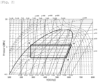
Fig. 2 is a pressure-enthalpy diagram (P-h diagram) of the heat medium circulation system in the embodiment; -
Fig. 3 is a schematic diagram of an installation configuration of an electric heating device in the embodiment; -
Fig. 4 is a block diagram of a control system of the heat medium circulation system in the embodiment; -
Fig. 5 is a correlation diagram of a power density and heater surface temperature of the electric heating device of the heat medium circulation system in the embodiment; and -
Fig. 6 is a flowchart for explaining a control operation of a blower and the electric heating device of the heat medium circulation system in the embodiment. - When an electric heating device is not energized until flammable refrigerant is ventilated by an outdoor blower, temperature of a bottom plate may drop and moisture on a surface of the bottom plate freezes. As a result, damage to a drainpipe may occur.
- Therefore, in the present disclosure, the operation of the blower device and the energization of the electric heating device are simultaneously started, and power consumption of the electric heating device is controlled to be lower than power consumption in a stable state for a predetermined time from start of energization of the electric heating device. As a result, even if the flammable refrigerant leaks, an amount of heat that does not ignite the flammable refrigerant is suppressed. By doing so, the electric heating device can be ventilated to exhaust the leaked refrigerant while suppressing the temperature drop of the bottom plate. This provides a heat medium circulation system that further improves reliability and safety of device.
- The embodiment will be described below in detail with reference to the drawings. Excessively detailed description will be omitted in some cases. For example, detailed description of already well-known matters, or redundant description of substantially the same configuration will be omitted in some cases. This is for preventing the following description becoming redundant more than necessary, and for making it easy for a person skilled in the art to understand.
- The accompanying drawing and the following description are provided so that the person skilled in the art can sufficiently understand the present disclosure, and it is not intended that they limit the subject matter described in claims.
- An embodiment of the present invention will be described below using
Figs. 1 to 5 . - In
Fig. 1 , a heatmedium circulation system 100 includes arefrigerant circuit 110, aheat medium circuit 120 and acontrol device 130. - The
refrigerant circuit 110 is a vapor compression type refrigeration cycle. Therefrigerant circuit 110 is configured by sequentially connecting acompressor 111, a use-side heat exchanger 112, anexpander 113 and a heat source-side heat exchanger 114 to one another through apipe 116. As refrigerant, propane which is flammable refrigerant is used. - The
refrigerant circuit 110 is provided with a four-way valve 115. The four-way valve 115 switches between a heating operation to produce warm water and a cooling operation to produce cold water. - The
refrigerant circuit 110 is housed in anoutdoor casing 140. Thecasing 140 includes anair blower 117 that flows outdoor air to the heat source-side heat exchanger 114. - The
heat medium circuit 120 is configured by sequentially connecting the use-side heat exchanger 112, a use-side terminal 122,switching valves conveyance pump 121 with aheat medium pipe 126. Theswitching valves conveyance pump 121 is a conveyance device for the heat medium. Water or antifreeze is used as the heat medium. - Further, the
heat medium circuit 120 includes a hotwater storage tank 123 in parallel with the use-side terminal 122. The hotwater storage tank 123 is connected through theheat medium pipe 126 that branches from theswitching valve 124b and joins theswitching valve 124a. - In the
heat medium circuit 120, awater heating device 127 having a heater element is provided on the downstream side of the use-side heat exchanger 112. At the highest position of thewater heating device 127, adeaerating device 128 which is capable of discharging gases flowing in theheat medium circuit 120 to the outside is provided. A discharge port of the deaeratingdevice 128 is open to the outdoor atmosphere. - Further, in the
heat medium circuit 120, a shut-offvalve 129a for stopping a flow of the heat medium is provided between theconveying device 121 and the use-side heat exchanger 112. In addition, a shut-off valve 129b is provided between the use-side heat exchanger 112 and thewater heating device 127. - In
Fig. 1 , a flow direction of the refrigerant during the heating operation is indicated by a solid arrow, and a flow direction of the refrigerant during the cooling operation is indicated by a broken arrow. - A state change of refrigerant in the heating operation and the cooling operation will be described using
Fig. 2 . - At the time of the heating operation, high pressure refrigerant (point a) discharged from the
compressor 111 flows into the use-side heat exchanger 112 through the four-way valve 115, and radiates heat to heat medium which flows through the use-side heat exchanger 112. The high pressure refrigerant (point b) after it radiates heat in the use-side heat exchanger 112 is decompressed and expanded by theexpander 113 and then, the refrigerant flows into the heat source-side heat exchanger 114. The low pressure refrigerant (point c) which flows into the heat source-side heat exchanger 114 absorbs heat from outside air and evaporates, and again returns to a suction side (point d) of thecompressor 111 through the four-way valve 115. - On the other hand, at the time of the cooling operation, high pressure refrigerant (point a) discharged from the
compressor 111 flows into the heat source-side heat exchanger 114 through the four-way valve 115, and radiates heat to the outside air in the heat source-side heat exchanger 114. The high pressure refrigerant (point b) after it radiates heat in the heat source-side heat exchanger 114 is decompressed and expanded by theexpander 113 and then, the refrigerant flows into the use-side heat exchanger 112. The low pressure refrigerant (point c) which flows into the use-side heat exchanger 112 absorbs heat from the heat medium which flows through the use-side heat exchanger 112 and evaporates, and again returns to the suction side (point d) of thecompressor 111 through the four-way valve 115. - Next, change of a state of heat medium in the
heat medium circuit 120 will be described. - First, at the time of the heating operation, heat medium is heated by high temperature refrigerant in the use-
side heat exchanger 112, and the heat medium is circulated by the conveyingdevice 121. The heat medium radiates heat, in the use-side terminal 122, for example, to the air in the living space. The heat medium is utilized for heating a use-side load. The heat medium which radiates heat in the use-side terminal 122 and whose temperature is lowered is again heated by the use-side heat exchanger 112. - Here, if an amount of heating in the use-
side heat exchanger 112 is less than an amount of heat that can sufficiently heat the use-side load, the heater element of thewater heating device 127 is energized, and the heat medium flowing into thewater heating device 127 is directly heated. - High temperature heat medium heated by the use-
side heat exchanger 112 circulates through thehot water tank 123 by switching operations of the switchingvalve 124a and the switchingvalve 124b. The high temperature heat medium is introduced from an upper portion of thehot water tank 123 into thehot water tank 123, and lower temperature heat medium is derived from a lower portion of thehot water tank 123, and is heated by the use-side heat exchanger 112. - On the other hand, at the time of the cooling operation, heat medium is cooled by the use-
side heat exchanger 112, and the heat medium is circulated by the conveyingdevice 121. According to this, the heat medium absorbs heat in the use-side terminal 122, and is utilized for cooling a use-side load. The heat medium which absorbs heat in the use-side terminal 122 and whose temperature rises is again cooled by the use-side heat exchanger 112. - The
control device 130 is provided in thecasing 140 of the heatmedium circulation system 100. Thecontrol device 130 controls a rotation speed of thecompressor 111, a rotation speed of the conveyingdevice 121, a throttle amount of theexpander 113, and applied voltage of thewater heating device 127. Thecontrol device 130 also switches the four-way valve 115 and the switchingvalves - In addition, when heating operation is performed, moisture in the air, etc., freezes and forms frost on the heat source-
side heat exchanger 114. As a result, the heating capacity and coefficient of performance decrease due to the deterioration of the heat transfer performance of the heat source-side heat exchanger 114. In such cases, the degree of frosting is determined from external temperature, operating time, or the temperature of the heat source-side heat exchanger 114, and the frost is melted and removed by the heat of the refrigerant. This is called defrosting operation. - Typical defrosting methods include reverse cycle defrosting and hot gas defrosting. Reverse cycle defrosting is a method of reversing the direction of refrigerant circulation by switching the four-
way valve 115, introducing the high-temperature and high-pressure gas refrigerant discharged from thecompressor 111 into the heat source-side heat exchanger 114, and melting the frost with the condensation heat of the gas refrigerant. Hot gas defrosting is a method of increasing the opening of theexpander 113 without switching the four-way valve 115, introducing the high-temperature and high-pressure gas refrigerant discharged from thecompressor 111 into the heat source-side heat exchanger 114 without reducing the pressure, and melting the frost with the heat of the gas refrigerant. - Next, the flow of drain water during defrosting operation will be described, using
Fig. 3 . - First, frost adheres to the surface of the heat transfer tubes and fins of the heat source-
side heat exchanger 114 during heating operation. In defrosting operation, the frost on the heat source-side heat exchanger 114 is heated and melted. The melted drain water flows down the fin surface of the heat source-side heat exchanger 114 from the lower side of the heat source-side heat exchanger 114 to abottom plate 141 of theoutdoor casing 140. The drain water flows out of thecasing 140 to the outside through adrain hole 142 provided in thebottom plate 141. - During defrosting operation, certain amount of the drain water that falls onto the
bottom plate 141 flows out through thedrain hole 142, but due to installation variations of thecasing 140 and structural constraints of thebottom plate 141, some of the drain water may stagnate in areas with a small slope to thedrain hole 142. Therefore, there is a possibility that the stagnant drain water will freeze during heating operation under environmental conditions below freezing. - If defrosting operation and heating operation are repeated in this state, ice will accumulate on the
bottom plate 141. In the worst case, the accumulated ice may come into contact with the fan blade of theair blower 117, causing theair blower 117 to malfunction. In addition, it may be occurred a problem such that ice may come into contact with a refrigerant pipe and cause damage to the refrigerant pipe. Therefore, there is a risk that reliability and safety will not be ensured. - Therefore, it is generally common practice to install an
electric heating device 143 on the surface of thebottom plate 141 to heat thebottom plate 141 and prevent the drain water from freezing. - The
electric heating device 143 can be composed of, for example, a sheathed heater, a silicone rubber heater, or a PTC heater. It is desirable to position theelectric heating device 143 in a suitable location with a heater length corresponding to the area of thebottom plate 141 so that the temperature of thebottom plate 141 can rise sufficiently. - In this embodiment, a heater with a power density of 2 W/cm2 is used for the
electric heating device 143 when the rated voltage is applied. - Next, configuration of the
control device 130 will be described usingFig. 4 . - The
control device 130 is composed of acontroller 131, auser interface 132, a high pressure-side pressure sensor 133, adischarge temperature sensor 134, a heat source-side heatexchange temperature sensor 135, an outsideair temperature sensor 136, a water-enteringtemperature sensor 137, a water-goingtemperature sensor 138 and agas sensor 139. Thecontroller 131 is provided with a microcomputer and a memory. Theuser interface 132 allows users to input information such as starting or stopping the operation of the device and setting the temperature of the heat medium to be generated. The high pressure-side pressure sensor 133 is provided in a discharge-side pipe of thecompressor 111, and detects discharge-side pressure. Thedischarge temperature sensor 134 detects discharged refrigerant temperature. The heat source-side heatexchange temperature sensor 135 is provided in a refrigerant pipe of the heat source-side heat exchanger 114, and detects saturation temperature of refrigerant which flows through the heat source-side heat exchanger 114. The outsideair temperature sensor 136 is provided on an outer surface of thecasing 140 of the heatmedium circulation system 100, and detects outside air temperature. The water-enteringtemperature sensor 137 detects temperature of heat medium which flows into the use-side heat exchanger 112 provided in theheat medium circuit 120. The water-goingtemperature sensor 138 detects temperature of heat medium which flows out from the use-side heat exchanger 112. Thegas sensor 139 is provided at the bottom of thecasing 140, and detects the concentration of flammable gas. - Action of the heat
medium circulation system 100 configured as described above will be described below. - The
controller 131 carries out the heating operation or the cooling operation based on input information from theuser interface 132. During operation, thecontroller 131 controls thecompressor 111 based on the detection value of the outsideair temperature sensor 136, the detection value of the water-goingtemperature sensor 138, and the rotation speed of thecompressor 11 based on the water-going temperature setting value of theuser interface 132. Further, thecontroller 131 controls the throttling amount of theexpander 113 while comparing it with the detection value of thedischarge temperature sensor 134 so that the discharge refrigerant temperature becomes the discharge temperature target value. The discharge temperature target value is determined based on the detection value of the high pressure-side pressure sensor 133 and the detection value of the heat source-side heatexchange temperature sensor 135. - In addition, during operation, the
controller 131 controls the rotation speed of theconveyance pump 121 so that the difference between the detection value of the water-goingtemperature sensor 138 and the detection value of the water-enteringtemperature sensor 137 becomes a predetermined temperature difference. - Furthermore, during the heating operation, the
controller 131 controls the applied voltage of the heater element of thewater heating device 127 so that the detection value of the water-goingtemperature sensor 138 becomes the water-going temperature setting value. - Operation of the
electric heating device 143 in heating and defrosting operations will be described. - When the heating operation is input to the
user interface 132, the opening of theexpander 113 is set to an initial value, theconveyance pump 121 is operated, and the heat medium in theheat medium circuit 120 is circulated. Thereafter, theair blower 117 is operated, and the air that has passed through the heat source-side heat exchanger 114 passes through thecasing 140 and is discharged to the outside. Further, at the same time as the operation of theair blower 117, energization of theelectric heating device 143 is started, and thebottom plate 141 is heated. However, the applied voltage is controlled lower than the rated voltage so that the power density is 1 W/cm2, and the surface temperature of theelectric heating device 143 is kept lower than normal, and theelectric heating device 143 is operated. - Then, when the rotation speed of the
air blower 117 becomes a rotation speed that becomes a preset air volume, the applied voltage is raised to the rated voltage to further raise the temperature of thebottom plate 141. - Further, when frosting is deposited on the heat source-
side heat exchanger 114 by heating operation, defrosting operation is started, but when reverse cycle defrosting is executed, theair blower 117 is stopped. - At this time, the applied voltage of the
electric heating device 143 is lowered so that the power density is 2 W/cm2 to 1 W/cm2, and the surface temperature is kept low. Then, the defrosting operation is completed and the heating operation is started. When the rotation speed of theair blower 117 becomes a rotation speed that becomes a preset air volume, the applied voltage is raised to the rated voltage to keep the surface temperature of theelectric heating device 143 high. - Furthermore, when the detection concentration of the
gas sensor 139 becomes higher than a predetermined concentration during heating operation, the energization of theelectric heating device 143 is stopped and the surface temperature of theelectric heating device 143 is lowered. - Here,
Fig. 5 is a graph showing the relationship between the power density and the surface temperature of the heater (electric heating device). Until the air volume passing through theelectric heating device 143 is sufficiently secured, the heater applied voltage is 1 W/cm2 at a heater surface temperature well below the propane flash point of 432 °C. Then, after the air volume is sufficiently secured, the heater applied voltage is lower than the flash point of propane and theelectric heating device 143 is operated at a surface temperature of 2 W/cm2, which is sufficient to heat thebottom plate 141. In this way, the voltage applied to the heater is controlled. - The operation at this time will be described in more detail using the flowchart shown in
Fig. 6 . First, the user instructs to start the heating operation by the operation of the user interface 132 (step S1). Then, according to the instruction, thecontrol device 130 operates theair blower 117 and at the same time applies a voltage having a power density of 1 W/cm2 to the electric heating device 143 (step S2). Then, thecompressor 111 and theconveyance pump 121 are operated, their rotation speed is controlled, and the opening degree of theexpander 113 is adjusted (step S3). Next, thecontrol device 130 detects the refrigerant concentration Cr in thecasing 140 by the gas sensor 139 (step S4). Then, preset refrigerant concentration Ca and the refrigerant concentration Cr are compared in advance, and it is determined whether or not the refrigerant concentration Cr is equal to or higher than the refrigerant concentration Ca (step S5). - If the refrigerant concentration Cr is equal to or higher than the refrigerant concentration Ca (YES in step S5), it is determined that a refrigerant leak has occurred in the
refrigerant circuit 110. Then, the power supply to theelectric heating device 143 is interrupted while theair blower 117 continues to operate (step S6). At the same time, thecompressor 111 and theconveyance pump 121 are stopped (step S7). Next, the shut-offvalves 129a and 129b are energized to actuate them in the closing direction, thereby stopping the flow of the heat medium (step S8). - If the refrigerant concentration Cr is less than the refrigerant concentration Ca (NO in step S5), it is determined that the flammable refrigerant has not leaked from the
refrigerant circuit 110, and the operation is continued. Then, it is determined whether theair blower 117 has operated for a predetermined time (step S9). If it is determined that the blower has operated for a predetermined time and a sufficient air flow has been secured (YES in step S9), the voltage is increased so that the power density of theelectric heating device 143 becomes 2 W/cm2 (step S10). - Then, preset defrost start temperature Tds and detection temperature Te of the heat source-side heat
exchange temperature sensor 135 are compared, and it is determined whether the detection temperature Te, which is the heat exchange temperature, is lower than the defrost start temperature Tds (step S11). - If the heat exchange temperature Te is equal to or higher than the defrost start temperature Tds (NO in step S11), it is determined that the frost amount on the heat source
side heat exchanger 114 is small and defrosting operation is not necessary, and the heating operation is continued. - On the other hand, if the heat exchange temperature Te is lower than the defrost start temperature Tds (YES in step S11), it is determined that the amount of frost on the heat source-
side heat exchanger 114 is large due to the heating operation and defrosting operation is necessary. Then, the four-way valve 115 is switched to the cooling position and theair blower 117 is stopped to start the defrost operation (step S12). - At this time, the applied voltage is lowered so that the power density of the
electric heating device 143 is lowered to 1 W/cm2, at the same time as theair blower 117 is stopped (step S13). - Then, the preset defrost end temperature Tde and the detected temperature Te of the heat source-side heat
exchange temperature sensor 135 are compared, and it is determined whether the heat exchange temperature Te is equal to or higher than the defrost end temperature Tde (step S14). If the heat exchange temperature Te is lower than the defrost end temperature Tde (NO in step S14), it is judged that frost remains on the heat sourceside heat exchanger 114, and the defrosting operation is continued. - On the other hand, if the heat exchange temperature Te is equal to or higher than the defrost end temperature Tde (YES in step S14), it is determined that the frost on the heat source-
side heat exchanger 114 has completely melted and defrosting is complete. Then, the four-way valve 115 is switched to the heating position and theair blower 117 is operated to start the heating operation (step S15). - As described above, in the embodiment of the present invention, the heat
medium circulation system 100 comprises arefrigerant circuit 110, aheat medium circuit 120, acontrol device 130, anair blower 117, abottom plate 141, and anelectric heating device 143. Therefrigerant circuit 110 is a vapor compression refrigeration cycle using a flammable refrigerant. Therefrigerant circuit 110 formed by annularly connecting acompressor 111, a use-side heat exchanger 112, anexpander 113, and a heat source-side heat exchanger 114. Theheat medium circuit 120 flows a liquid heat medium that heats and cools the use-side load. Theair blower 117 circulates outdoor air to the heat source-side heat exchanger 114. Theelectric heating device 143 is provided on the surface of thebottom plate 141 and electrically heats thebottom plate 141. - The
electric heating device 143 is energized at the same time as theair blower 117 is started, and is controlled to be lower than the power consumption in the stable state for a predetermined time after the start of energization. - As a result, the
electric heating device 143 is energized at the same time as theair blower 117 is started. Therefore, the temperature drop of thebottom plate 141 due to air blow is prevented, and the temperature of thebase plate 141 rises rapidly. - In addition, in the event that gas leaks and stagnates on the
bottom plate 141 while the operation is stopped, the wind speed is low immediately after theair blower 117 starts, and the stagnant gas is difficult to diffuse. However, the power consumption of theelectric heating device 143 is controlled to be lower than the power consumption in the stable state. Therefore, the power density of theelectric heating device 143 is low for a predetermined time after theair blower 117 starts, and the surface temperature of theelectric heating device 143 is kept low until the atmosphere gas of theelectric heating device 143 is ventilated. - Therefore, it is possible to simultaneously prevent ignition of the leaked refrigerant by the heat of the
electric heating device 143 and prevent freezing of thebottom plate 141. As a result, the safety against leakage of flammable refrigerant is further improved. - As in the embodiment of the present invention, the power density of the
electric heating device 143 is 2 W/cm2 or less, and the power density may be controlled to be less than 1 W/cm2 for a predetermined time after energization. - As a result, the power density of the
electric heating device 143 is low during the period when the wind speed is low after theair blower 117 starts, and the surface temperature is kept at a temperature sufficiently lower than the ignition temperature of propane. Therefore, even if flammable gas is stagnant, it will not ignite. - Therefore, it is possible to simultaneously prevent ignition of the leaked refrigerant by the heat of the
electric heating device 143 and prevent freezing of thebottom plate 141. As a result, the safety against leakage of flammable refrigerant is further improved. - In the embodiment of the present invention, the predetermined time period for controlling the power consumption of the
electric heating device 143 to be low may be set to the time until the wind speed of theair blower 117 reaches a predetermined wind speed that can sufficiently exhaust the stagnant gas. - As a result, the flammable gas that has leaked from the
refrigerant circuit 110 and is stagnant near theelectric heating device 143 is diffused by the wind generated by theair blower 117. Until the flammable gas is exhausted outside thecasing 140, the surface temperature of theelectric heating device 143 is kept at a temperature sufficiently lower than the ignition temperature of propane, so that the flammable gas will not ignite even if it stagnates. - In the embodiment of the present invention, if the gas concentration detected by the
gas sensor 139 exceeds a predetermined gas concentration, theair blower 117 may be kept operating and the power supply to theelectric heating device 143 may be shut off. - This allows for a reliable determination that a flammable refrigerant has leaked. In the event of a gas leak, the
air blower 117 will exhaust the flammable gas and the surface temperature will drop rapidly due to the interruption of the power supply to theelectric heating device 143. This further enhances safety. - In the embodiment of the present invention, the flammable refrigerant may be propane or a mixed refrigerant containing propane. This can lower the global warming potential (GWP) and suppress the adverse effects on the environment in the event of a refrigerant leak. Therefore, the environmental impact is improved.
- The foregoing embodiments have been described by way of example of the technology disclosed in the present application. However, the technology disclosed herein is not limited thereto, and can be applied to embodiments with modifications, replacements, additions, and omissions. It is also possible to combine the various components described in the above embodiments to create new embodiments.
- Therefore, other embodiments are exemplified below.
- In this embodiment, a cooling and heating water heater is described as an example of the heat
medium circulation system 100. The heatmedium circulation system 100 may be any system that can cool or heat a liquid. Therefore, the heatmedium circulation system 100 is not limited to cooling and heating water heaters. However, if a cooling and heating water heater is used as the heatmedium circulation system 100, it can meet the annual heat demand of a house. A chiller may also be used as the heatmedium circulation system 100. If a chiller is used as the heatmedium circulation system 100, it can meet the heating and cooling load used in factories, etc. Therefore, the energy efficiency of factories can be improved. - In this embodiment, a refrigerant concentration sensor is described as an example of a leak sensor. The leak sensor may be any sensor that can detect the leakage of refrigerant from the
refrigerant circuit 110 to theheat medium circuit 120. Therefore, the leak sensor is not limited to a refrigerant concentration sensor. However, if a refrigerant concentration sensor is used as a leak sensor, it can be realized with a simple configuration. A pressure sensor that detects the pressure of therefrigerant circuit 110 or a thermistor that detects the operating temperature of the refrigerant can also be used as a leak sensor. If the pressure or temperature of therefrigerant circuit 110 is detected, the sensor for operating control can be shared. Therefore, it can be manufactured inexpensively. - In this embodiment, an example of the installation position of the
electric heating device 143 is described, in which it is installed on the surface of thebottom plate 141 of thecasing 140. The installation position of theelectric heating device 143 may be any position where the temperature of thebottom plate 141 rises when theelectric heating device 143 is energized, and the drain water does not freeze. Therefore, the installation position of theelectric heating device 143 is not limited to the surface of thebottom plate 141. - However, if the
electric heating device 143 is installed on the surface of thebottom plate 141, thebottom plate 141 and the drain water can be directly heated, so that the heat exchange efficiency can be improved. Further, theelectric heating device 143 may also be installed on the back surface of thebottom plate 141. If theelectric heating device 143 is installed on the back surface of thebottom plate 141, the refrigerant gas will not come into direct contact with it in case of a short circuit and sparking of theelectric heating device 143. Therefore, it has the effect of more reliably preventing ignition, such as in the event of sparking. - In this embodiment, a circuit is described as an example of the installation position of shut-off
valves 129a and 129b, which is installed between the conveyingdevice 121 and the user-side heat exchanger 112 or between the user-side heat exchanger 112 and thewater heating device 127. The shut-offvalves 129a and 129b should be installed in a position where the refrigerant does not flow into the living space when the refrigerant leaks into theheat medium circuit 120. Therefore, the installation position of the shut-offvalves 129a and 129b is not limited to between the conveyingdevice 121 and the user-side heat exchanger 112 or between the user-side heat exchanger 112 and thewater heating device 127. However, by installing the shut-offvalves 129a and 129b downstream of the discharge device, the leaked refrigerant that exists in theheat medium circuit 120 between the shut-offvalves 129a and 129b can be discharged into the atmosphere even after the shut-off. Therefore, safety is further improved. - The present disclosure is applicable to a heat medium circulation system using a flammable refrigerant in a refrigerant circuit. Specifically, the present disclosure is applicable to hot water heaters, commercial chillers, and the like.
-
- 100
- heat medium circulation system
- 110
- refrigerant circuit
- 111
- compressor
- 112
- use-side heat exchanger
- 113
- expander
- 114
- heat source-side heat exchanger
- 115
- four-way valve
- 116
- pipe
- 117
- air blower
- 120
- heat medium circuit
- 121
- conveying pump
- 122
- use-side terminal
- 123
- hot water tank
- 124a
- switching valve
- 124b
- switching valve B
- 126
- heat medium pipe
- 127
- water heating device
- 128
- deaerating device
- 129a
- shut-off valve
- 129b
- switching valve
- 130
- control device
- 131
- controller
- 132
- user interface
- 133
- high pressure-side pressure sensor
- 134
- discharge temperature sensor
- 135
- heat source-side heat exchange temperature sensor
- 136
- outside air temperature sensor
- 137
- water-entering temperature sensor
- 138
- water-going temperature sensor
- 139
- gas sensor
- 140
- casing
- 141
- bottom plate
- 142
- drain hole
- 143
- electric heating device
Claims (5)
- A heat medium circulation system comprising:a refrigerant circuit in which a compressor, a use-side heat exchanger, an expander, and a heat source-side heat exchanger are connected annularly and a flammable refrigerant is used;an air blower for flowing air to the heat source-side heat exchanger;a casing accommodating at least the refrigerant circuit and the air blower;an electric heating device provided on a surface of a bottom plate of the casing; anda control device, whereinthe control device simultaneously starts operation of the air blower and energization of the electric heating device, and controls such that power consumption of the electric heating device is lower than power consumption in a stable state for a predetermined time from start of energization of the electric heating device.
- The heat medium circulation system according to claim 1, wherein a power density of the electric heating device is 2 W/cm2 or less, and
the control device controls the power density to be less than 1 W/cm2 during the predetermined time. - The heat medium circulation system according to claim 1 or claim 2, wherein the predetermined time is a time until an air volume generated by the air blower becomes a predetermined air volume or more.
- The heat medium circulation system according to any one of claims 1 to 3, comprising:a leak sensor which detects leakage of the flammable refrigerant in the casing, whereinwhen the leak sensor detects the leakage of the flammable refrigerant, the control device continues operation of the air blower and stops energization of the electric heating device.
- The heat medium circulation system according to any one of claims 1 to 4, wherein the flammable refrigerant is propane or a mixed refrigerant containing the propane.
Applications Claiming Priority (2)
| Application Number | Priority Date | Filing Date | Title |
|---|---|---|---|
| JP2021167893 | 2021-10-13 | ||
| PCT/JP2022/033866 WO2023062989A1 (en) | 2021-10-13 | 2022-09-09 | Heat medium circulation system |
Publications (3)
| Publication Number | Publication Date |
|---|---|
| EP4417898A1 true EP4417898A1 (en) | 2024-08-21 |
| EP4417898A4 EP4417898A4 (en) | 2025-01-15 |
| EP4417898B1 EP4417898B1 (en) | 2026-02-25 |
Family
ID=85987450
Family Applications (1)
| Application Number | Title | Priority Date | Filing Date |
|---|---|---|---|
| EP22880685.7A Active EP4417898B1 (en) | 2021-10-13 | 2022-09-09 | Heat medium circulation system |
Country Status (3)
| Country | Link |
|---|---|
| EP (1) | EP4417898B1 (en) |
| JP (1) | JP7788647B2 (en) |
| WO (1) | WO2023062989A1 (en) |
Families Citing this family (1)
| Publication number | Priority date | Publication date | Assignee | Title |
|---|---|---|---|---|
| CN117190332A (en) * | 2023-10-13 | 2023-12-08 | 青岛海尔智慧楼宇科技有限公司 | Chassis components for air conditioners, air conditioner outdoor units and air conditioners |
Family Cites Families (10)
| Publication number | Priority date | Publication date | Assignee | Title |
|---|---|---|---|---|
| JP4269896B2 (en) * | 2003-10-31 | 2009-05-27 | パナソニック株式会社 | Vending machine cooling and heating device |
| JP2009079818A (en) * | 2007-09-26 | 2009-04-16 | Panasonic Corp | vending machine |
| JP5484937B2 (en) * | 2010-02-01 | 2014-05-07 | 三菱重工業株式会社 | Outdoor unit and air conditioner |
| JP5487053B2 (en) * | 2010-08-25 | 2014-05-07 | 日立アプライアンス株式会社 | refrigerator |
| JP5215367B2 (en) * | 2010-10-04 | 2013-06-19 | 日立アプライアンス株式会社 | refrigerator |
| JP2015055455A (en) | 2013-09-13 | 2015-03-23 | 三菱電機株式会社 | Outdoor unit and air conditioner |
| JP6452961B2 (en) * | 2014-06-05 | 2019-01-16 | 日立ジョンソンコントロールズ空調株式会社 | Air conditioner |
| JP6557085B2 (en) * | 2015-07-27 | 2019-08-07 | シャープ株式会社 | Air conditioner |
| CN106568134A (en) * | 2015-10-08 | 2017-04-19 | 孙海潮 | Refrigerating and heating pump type frostless air conditioner outdoor unit |
| JP6611928B2 (en) * | 2016-05-17 | 2019-11-27 | 三菱電機株式会社 | Air conditioner |
-
2022
- 2022-09-09 JP JP2023555021A patent/JP7788647B2/en active Active
- 2022-09-09 EP EP22880685.7A patent/EP4417898B1/en active Active
- 2022-09-09 WO PCT/JP2022/033866 patent/WO2023062989A1/en not_active Ceased
Also Published As
| Publication number | Publication date |
|---|---|
| JP7788647B2 (en) | 2025-12-19 |
| WO2023062989A1 (en) | 2023-04-20 |
| EP4417898B1 (en) | 2026-02-25 |
| EP4417898A4 (en) | 2025-01-15 |
| JPWO2023062989A1 (en) | 2023-04-20 |
Similar Documents
| Publication | Publication Date | Title |
|---|---|---|
| EP4075078A1 (en) | Heat medium circulation system | |
| EP2395302B1 (en) | Heat pump-type hot-water supply and air-conditioning device | |
| JP4867749B2 (en) | Heat pump water heater | |
| EP2940407A1 (en) | Heat pump hot water heater | |
| CN104654495A (en) | Hot and cold water air conditioning system | |
| JP5053430B2 (en) | Air conditioner | |
| EP4443075A1 (en) | Heat medium circulation system | |
| JP2002107014A (en) | Air conditioner | |
| JPWO2017029695A1 (en) | Air conditioner | |
| JP2009036485A (en) | Water heater | |
| JP2013119954A (en) | Heat pump hot water heater | |
| CN114909699B (en) | Defrosting control method, central controller and heating system | |
| US6263686B1 (en) | Defrost control method and apparatus | |
| CN105247293A (en) | Heat pump system | |
| EP4417898A1 (en) | Heat medium circulation system | |
| KR100712196B1 (en) | Heat pump system and outdoor unit defrosting method | |
| JP2011252621A (en) | Heat pump type hot water supplying/air conditioning apparatus | |
| EP3865802B1 (en) | Plate heat exchanger and heat pump apparatus | |
| JP4622990B2 (en) | Air conditioner | |
| JP3876721B2 (en) | Water heater | |
| JP2018066515A (en) | Method of controlling heat pump hot water heating system | |
| JP7554995B2 (en) | Heat Transfer Medium Circulation System | |
| KR101689967B1 (en) | Heat pump device | |
| JP2008224067A (en) | Heat pump water heater | |
| JP5516332B2 (en) | Heat pump type hot water heater |
Legal Events
| Date | Code | Title | Description |
|---|---|---|---|
| STAA | Information on the status of an ep patent application or granted ep patent |
Free format text: STATUS: THE INTERNATIONAL PUBLICATION HAS BEEN MADE |
|
| PUAI | Public reference made under article 153(3) epc to a published international application that has entered the european phase |
Free format text: ORIGINAL CODE: 0009012 |
|
| STAA | Information on the status of an ep patent application or granted ep patent |
Free format text: STATUS: REQUEST FOR EXAMINATION WAS MADE |
|
| 17P | Request for examination filed |
Effective date: 20240320 |
|
| AK | Designated contracting states |
Kind code of ref document: A1 Designated state(s): AL AT BE BG CH CY CZ DE DK EE ES FI FR GB GR HR HU IE IS IT LI LT LU LV MC MK MT NL NO PL PT RO RS SE SI SK SM TR |
|
| A4 | Supplementary search report drawn up and despatched |
Effective date: 20241212 |
|
| DAV | Request for validation of the european patent (deleted) | ||
| DAX | Request for extension of the european patent (deleted) | ||
| GRAP | Despatch of communication of intention to grant a patent |
Free format text: ORIGINAL CODE: EPIDOSNIGR1 |
|
| STAA | Information on the status of an ep patent application or granted ep patent |
Free format text: STATUS: GRANT OF PATENT IS INTENDED |
|
| RIC1 | Information provided on ipc code assigned before grant |
Ipc: F25B 1/00 20060101AFI20250912BHEP Ipc: F25B 47/02 20060101ALI20250912BHEP Ipc: F25B 49/02 20060101ALI20250912BHEP Ipc: F24D 19/00 20060101ALI20250912BHEP Ipc: F24D 19/08 20060101ALI20250912BHEP Ipc: F24H 15/12 20220101ALI20250912BHEP Ipc: F24H 15/136 20220101ALI20250912BHEP Ipc: F24H 15/144 20220101ALI20250912BHEP Ipc: F24D 17/02 20060101ALI20250912BHEP Ipc: F24F 11/36 20180101ALI20250912BHEP Ipc: F24H 15/20 20220101ALI20250912BHEP Ipc: F24H 15/242 20220101ALI20250912BHEP Ipc: F24H 15/254 20220101ALI20250912BHEP Ipc: F24H 15/281 20220101ALI20250912BHEP Ipc: F24H 15/31 20220101ALI20250912BHEP Ipc: F24H 15/345 20220101ALI20250912BHEP Ipc: F24H 15/38 20220101ALI20250912BHEP Ipc: F24H 15/395 20220101ALI20250912BHEP Ipc: F24H 15/45 20220101ALI20250912BHEP Ipc: F25B 13/00 20060101ALI20250912BHEP |
|
| INTG | Intention to grant announced |
Effective date: 20251001 |
|
| GRAS | Grant fee paid |
Free format text: ORIGINAL CODE: EPIDOSNIGR3 |
|
| GRAA | (expected) grant |
Free format text: ORIGINAL CODE: 0009210 |
|
| STAA | Information on the status of an ep patent application or granted ep patent |
Free format text: STATUS: THE PATENT HAS BEEN GRANTED |
|
| AK | Designated contracting states |
Kind code of ref document: B1 Designated state(s): AL AT BE BG CH CY CZ DE DK EE ES FI FR GB GR HR HU IE IS IT LI LT LU LV MC MK MT NL NO PL PT RO RS SE SI SK SM TR |
|
| REG | Reference to a national code |
Ref country code: CH Ref legal event code: F10 Free format text: ST27 STATUS EVENT CODE: U-0-0-F10-F00 (AS PROVIDED BY THE NATIONAL OFFICE) Effective date: 20260225 Ref country code: GB Ref legal event code: FG4D |
|
| REG | Reference to a national code |
Ref country code: DE Ref legal event code: R096 Ref document number: 602022031341 Country of ref document: DE |
|
| REG | Reference to a national code |
Ref country code: IE Ref legal event code: FG4D |