EP4417819A1 - Verstellsystem für einen verdichter - Google Patents
Verstellsystem für einen verdichter Download PDFInfo
- Publication number
- EP4417819A1 EP4417819A1 EP24154204.2A EP24154204A EP4417819A1 EP 4417819 A1 EP4417819 A1 EP 4417819A1 EP 24154204 A EP24154204 A EP 24154204A EP 4417819 A1 EP4417819 A1 EP 4417819A1
- Authority
- EP
- European Patent Office
- Prior art keywords
- actuator
- valve
- adjustment system
- adjusting
- locking
- Prior art date
- Legal status (The legal status is an assumption and is not a legal conclusion. Google has not performed a legal analysis and makes no representation as to the accuracy of the status listed.)
- Pending
Links
- 230000000903 blocking effect Effects 0.000 claims description 12
- 230000008054 signal transmission Effects 0.000 claims description 2
- 239000012530 fluid Substances 0.000 description 10
- 238000002485 combustion reaction Methods 0.000 description 2
- 238000005299 abrasion Methods 0.000 description 1
- 230000001419 dependent effect Effects 0.000 description 1
- 238000012986 modification Methods 0.000 description 1
- 230000004048 modification Effects 0.000 description 1
Images


Classifications
-
- F—MECHANICAL ENGINEERING; LIGHTING; HEATING; WEAPONS; BLASTING
- F04—POSITIVE - DISPLACEMENT MACHINES FOR LIQUIDS; PUMPS FOR LIQUIDS OR ELASTIC FLUIDS
- F04D—NON-POSITIVE-DISPLACEMENT PUMPS
- F04D29/00—Details, component parts, or accessories
- F04D29/40—Casings; Connections of working fluid
- F04D29/52—Casings; Connections of working fluid for axial pumps
- F04D29/54—Fluid-guiding means, e.g. diffusers
- F04D29/56—Fluid-guiding means, e.g. diffusers adjustable
- F04D29/563—Fluid-guiding means, e.g. diffusers adjustable specially adapted for elastic fluid pumps
-
- F—MECHANICAL ENGINEERING; LIGHTING; HEATING; WEAPONS; BLASTING
- F01—MACHINES OR ENGINES IN GENERAL; ENGINE PLANTS IN GENERAL; STEAM ENGINES
- F01D—NON-POSITIVE DISPLACEMENT MACHINES OR ENGINES, e.g. STEAM TURBINES
- F01D9/00—Stators
- F01D9/02—Nozzles; Nozzle boxes; Stator blades; Guide conduits, e.g. individual nozzles
- F01D9/04—Nozzles; Nozzle boxes; Stator blades; Guide conduits, e.g. individual nozzles forming ring or sector
- F01D9/041—Nozzles; Nozzle boxes; Stator blades; Guide conduits, e.g. individual nozzles forming ring or sector using blades
-
- F—MECHANICAL ENGINEERING; LIGHTING; HEATING; WEAPONS; BLASTING
- F01—MACHINES OR ENGINES IN GENERAL; ENGINE PLANTS IN GENERAL; STEAM ENGINES
- F01D—NON-POSITIVE DISPLACEMENT MACHINES OR ENGINES, e.g. STEAM TURBINES
- F01D17/00—Regulating or controlling by varying flow
- F01D17/10—Final actuators
- F01D17/12—Final actuators arranged in stator parts
- F01D17/14—Final actuators arranged in stator parts varying effective cross-sectional area of nozzles or guide conduits
- F01D17/16—Final actuators arranged in stator parts varying effective cross-sectional area of nozzles or guide conduits by means of nozzle vanes
-
- F—MECHANICAL ENGINEERING; LIGHTING; HEATING; WEAPONS; BLASTING
- F01—MACHINES OR ENGINES IN GENERAL; ENGINE PLANTS IN GENERAL; STEAM ENGINES
- F01D—NON-POSITIVE DISPLACEMENT MACHINES OR ENGINES, e.g. STEAM TURBINES
- F01D17/00—Regulating or controlling by varying flow
- F01D17/10—Final actuators
- F01D17/12—Final actuators arranged in stator parts
- F01D17/14—Final actuators arranged in stator parts varying effective cross-sectional area of nozzles or guide conduits
- F01D17/16—Final actuators arranged in stator parts varying effective cross-sectional area of nozzles or guide conduits by means of nozzle vanes
- F01D17/162—Final actuators arranged in stator parts varying effective cross-sectional area of nozzles or guide conduits by means of nozzle vanes for axial flow, i.e. the vanes turning around axes which are essentially perpendicular to the rotor centre line
-
- F—MECHANICAL ENGINEERING; LIGHTING; HEATING; WEAPONS; BLASTING
- F05—INDEXING SCHEMES RELATING TO ENGINES OR PUMPS IN VARIOUS SUBCLASSES OF CLASSES F01-F04
- F05D—INDEXING SCHEME FOR ASPECTS RELATING TO NON-POSITIVE-DISPLACEMENT MACHINES OR ENGINES, GAS-TURBINES OR JET-PROPULSION PLANTS
- F05D2270/00—Control
- F05D2270/60—Control system actuates means
- F05D2270/64—Hydraulic actuators
Definitions
- the invention relates to an adjustment system for a compressor in a gas turbine, in particular in an aircraft gas turbine, for adjusting adjustable guide vanes, comprising an actuator device with a first actuator for adjusting the guide vanes, an adjusting device with a first control valve for hydraulically actuating the first actuator, and wherein the adjusting device can adjust and fix the first actuator by the hydraulic actuation.
- An adjustment system has an actuator device with a first actuator for adjusting the guide vanes and an adjusting device with a first control valve for hydraulically actuating the first actuator, wherein the adjusting device can adjust and fix the first actuator by means of the hydraulic actuation.
- the actuator device is assigned a locking device for additional fixation and can be fixed in a position by the locking device.
- the additional fixation can prevent or at least reduce movement of the actuators or the actuator device and thus of the guide vanes, thus advantageously reducing the load and wear on the bearings of the guide vanes.
- the control valve is not completely sealed in the zero position. In this case, it is pushed out of the zero position by the forces from the engine. After a threshold value is exceeded, the controller intervenes and triggers a return movement. Depending on the leakage in the control valve, this can happen more often per second, which can lead to constant, very small movements in the system.
- the actuator device can have a second actuator, which can also be hydraulically controlled by the first actuating device.
- the first and second actuators can form a master-slave system in this configuration, whereby only the position of the first actuator as master is decisive for the control of the actuator device.
- the two actuators can be fluidly connected to one another, whereby the respective interior of the actuators is divided into two chambers by an actuator piston and one of the two of one actuator is fluidly connected to one of the two chambers of the other actuator. This means that the two actuators can be easily controlled and moved together.
- the locking device can hydraulically lock and release the actuator device, in particular the first actuator.
- a particularly simple system is created by hydraulic fixation, since no further actuators or modifications to the actuators are required.
- the locking device can achieve a mechanical locking of the actuator device and can be controlled hydraulically or electronically for this purpose.
- the actuator can be electromagnetically locked by the locking device.
- the adjustment system can be developed in such a way that the locking device comprises a first locking valve.
- the additional fixation of the actuator device can be achieved particularly easily by means of a locking valve.
- the first locking valve is arranged in a hydraulic line between the first control valve and the first actuator This makes it particularly easy and cost-effective to separate and fix the first actuator from the rest of the hydraulic system.
- the adjustment system can be developed in such a way that the locking device locks a hydraulic line between the first actuator and the first control valve in a blocking position of the blocking valve in order to fix the first actuator. This additionally fixes the blocking position and prevents the blocking valve from drifting.
- the adjustment system can comprise a control unit for controlling the first control valve, whereby the locking device can be locked and released by the control unit.
- the control unit can be programmed depending on flight conditions and mission types or can react to correspondingly received sensor data and thus achieve the best possible control of the control valve and the locking device.
- the locking device can be locked and released electrically, electromechanically, electrohydraulically and/or electromagnetically by the control unit. This achieves robust control.
- the first actuator has a first sensor for detecting a position of the first actuator, wherein the sensor is electronically connected to the control unit for signal transmission, and that the locking device is locked or released by the control unit depending on the position of the first actuator.
- the first control valve can be a continuous valve, in particular a servo valve, particularly preferably an electrically controlled, hydraulically operated servo valve in a 4/3-way valve with a middle blocking position.
- Continuous valves allow very good control of the adjustment system and servo valves in particular represent a very precise and robust way of controlling the hydraulic flow of the control system.
- Servo valves can be used to overcome the high forces occurring in the flow channel of the gas turbine very well and the guide vanes can still be adjusted precisely. In particular in combination with an additional locking device, the forces occurring in a blocking position in which the servo valve is only intended to seal can also be reduced or avoided. This can advantageously avoid readjustment.
- the actuator device can comprise a second actuator, wherein the actuating device can comprise a second control valve for hydraulically actuating the second actuator, and wherein the second control valve can adjust and fix the second actuator by means of the hydraulic actuation.
- the actuating device can comprise a second control valve for hydraulically actuating the second actuator, and wherein the second control valve can adjust and fix the second actuator by means of the hydraulic actuation.
- the locking device can comprise a second locking valve, wherein the second locking valve can be arranged in a second hydraulic line between the second control valve and the second actuator. This allows the actuators to be advantageously fixed separately, which allows particularly precise control of the adjustment system.
- a gas turbine 1 designed as an aircraft gas turbine which comprises a compressor 2, the stator stages of which are adjustable and are controlled by an actuating system 3 according to the invention.
- Each stator stage comprises several adjustable guide vanes 4, which can be adjusted by the actuating system 3 via an adjusting ring 5 and an adjusting lever 6.
- a plurality of adjusting levers 6 are provided on each adjusting ring 5 for controlling the respective guide vanes 4.
- a group of adjusting rings 5 can be provided, of which one adjusting ring 5 is assigned to a guide vane stage or a stator stage.
- the guide vanes 4 are rotatably mounted about their axis of rotation, which is formed by a bearing pin (not shown), and can be rotated by the respective adjusting lever 6, which in turn is rotated by the respective adjusting ring 5.
- the gas turbine 1 further comprises, downstream of the compressor 2, a combustion chamber 7 and a turbine 8, which are arranged together with the compressor 2 in a flow channel 9, in particular a core flow channel, of the gas turbine 1.
- Fig. 2a shows a schematic representation of the first embodiment of the adjustment system 3.
- the adjustment system 3 comprises an actuator device 10 for moving and adjusting the adjusting ring 5 or the group of adjusting rings 5, wherein a plurality of adjusting levers 6 are arranged on each of the adjusting rings 5 and wherein each of the adjusting rings 5 is connected via one of the adjusting levers 6 to one of the guide vanes 4 from the plurality of guide vanes 4.
- the adjustment system 3 further comprises an adjusting device 20 which is hydraulically connected to the actuator device 10 and is controlled by a control unit 40. Furthermore, the actuator device 10 is assigned a locking device 30 which can additionally lock the actuator device 10.
- the actuator device 10 is supplied with hydraulic fluid by a hydraulic system 50 and can communicate with the control unit 40 via an electrical system 60, wherein the control unit 40 controls the adjusting device 20 based on a position of the actuator device 10.
- the adjusting device 20 controls the flow of hydraulic fluid into the actuator device 10 based on the control by the control unit 40.
- the actuator device 10 comprises a first actuator 11 and a second actuator 12.
- the two actuators 11, 12 are both designed as double-acting cylinders, wherein the actuators 11, 12 each have an actuator piston 15, 16, which is connected and moves via a respective piston rod 15', 16' and a respective linkage 15", 16" arranged on the corresponding piston rod with an adjusting ring 5 or with a group of adjusting rings 5.
- a group of adjusting rings 5 are in Fig. 2b shown schematically.
- the actuators 11, 12 are arranged distributed around the adjusting ring 5 or the group of adjusting rings 5.
- Fig.1 two adjusting rings 5 are shown schematically, but it is the same adjusting ring 5, whereby the actuators are not arranged next to each other as shown, but rather at different positions around the adjusting ring 5 or the group of adjusting rings 5 and move.
- the first actuator 11 in the present embodiment has a sensor 13 which detects the adjustment path of the actuator piston 15 and signals it to the control unit 40.
- Both actuators 11, 12 have, due to their design an actuator interior 17, 18 in which the respective actuator piston 15, 16 moves, whereby two chambers separated by the respective actuator piston 15, 16 are formed.
- Both chambers of the respective actuator piston 15, 16 are each connected to a separate hydraulic line 51, which is each individually controlled by the hydraulic system 50 with hydraulic fluid.
- the two actuators 11, 12 or one of their chambers is in fluid communication with one of the two chambers of the other actuator, whereby pressure equalization can take place and the two actuators are hydraulically controlled evenly.
- the flow of the hydraulic fluid is controlled via the actuating device 20, for which purpose the actuating device 20 has a first control valve 21.
- the first control valve 21, designed as a servo valve is a 4/3-way valve with a middle blocking position and is connected to one of the two hydraulic lines 51 to the chambers of the respective actuator.
- a first position allows flow in a first direction
- the second middle position is designed as a blocking position
- a third position allows flow in a second opposite direction.
- the blocking position serves to hold the actuators 11, 12 in position, while the first and third positions apply a force to the actuator pistons 15, 16 and move them, which ultimately adjusts the guide vanes 4.
- the first control valve 21 is adjusted to the three positions electrohydraulically by the control unit 40.
- the hydraulic system 50 provides the necessary pressure in the hydraulic lines 51 and to the actuator device 10 or the actuating device 20 via a hydraulic pump 54 from a hydraulic accumulator 53, with a pressure sequence valve 55 being connected between the hydraulic pump 54 connected to a supply line (IN) and a discharge line (OUT), which makes it possible to pump hydraulic fluid into the discharge line (OUT) even if the pressure in the discharge line is too low. This enables hydraulic fluid to flow back or be sucked in from the hydraulic accumulator 53 into the actuator device 10 in both hydraulic lines.
- the actuator device 10 during operation of the gas turbine 1 is subjected to constant feedback by a flow impingement of the Guide vanes 4 are exposed to. This leads to a constant movement of the actuator device 10 and the adjusting device 20 and consequently a constant compensation and readjustment of the adjustment system 3 by the control unit 40. It has also been found that the constantly occurring minimal movements lead to a constant load and abrasion of the bearings of the adjustable guide vanes 4.
- a locking device 30 is therefore additionally arranged according to the invention between the actuating device 20 and the actuator device 10, the locking device 30 also being controlled by the control unit 40.
- the control unit 40 is connected to the first actuator 11, the first control valve 21 and the locking device 30 via electrical lines 61 in order to send the control signals or to receive the stroke position of the actuator 11.
- the locking device 30 can block the actuator device 10 and thus fix a position of the actuators or prevent movement of the actuators 11, 12.
- the locking device 30 can be designed as a separating device and separate a hydraulic connection between the actuator device and the actuating device. This fixes the volume of the hydraulic fluid present in the actuator device 10 and prevents feedback in the direction of the actuating device 20, the hydraulic pump 54 or the follow-up valve 55.
- the locking device 30 comprises a first locking valve 31, which can be operated in a flow position and a blocking position.
- the first locking valve 31 is controlled and adjusted electrically by the control unit 40 via an electrical line 61.
- the blocking position is then selected by the control unit 40 when the actuators 11, 12 are to be held in position. This separates the hydraulic connection between the actuators 11, 12 and the first control valve 21, whereby the actuators 11, 12 and thus the adjustable guide vanes 4 are held in position in a simple manner.
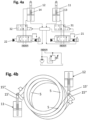
- Fig. 4a and Fig. 4b a third embodiment of an adjustment system 3 according to the invention is shown.
- the actuator device 10 has two individually controllable actuators 11, 12, each of which is assigned its own control valve 21, 22 via a hydraulic line. Unlike in the previous embodiments, no compensation lines are provided between the interior spaces 17, 18 of the two actuators 11, 12.
- the first actuator 11 can be controlled by the first control valve 21 and the second actuator 12 can be controlled by the second control valve 22 independently of one another.
- the two control valves 21, 22 are each as in the embodiment in Fig.3 described by the control unit 40 electrically controlled and electrohydraulically adjusted.
- Each of the two actuators 11, 12 is designed with its own sensor 13, 14, which signals the stroke position of the corresponding actuator 11, 12 to the control unit 40.
- the control unit 40 can control and adjust the actuators 11, 12 individually.
- a first locking valve 31 or second locking valve 32 of the locking device 30 is arranged between each of the actuators 11, 12 and the respective hydraulically associated first control valve 21 or second control valve 22.
- the first locking valve 31 is arranged between the first actuator 11 and the first control valve 21.
- the second locking valve 32 is arranged between the second actuator 12 and the second control valve 22.
- the two locking valves 31, 32 can be individually controlled and adjusted by the control unit 40, like the locking valve 31 described in the second embodiment. As a result, each actuator 11, 12 can be individually hydraulically separated from the rest of the hydraulic system 50 and thus additionally fixed.
- the control unit 40 is connected via electrical lines 61 to the first actuator 11 and the second actuator 12, the first control valve 21 and the second control valve 22 and the two locking valves 31, 32 in order to send the control signals or to receive the stroke position of the actuators 11, 12.
Landscapes
- Engineering & Computer Science (AREA)
- Mechanical Engineering (AREA)
- General Engineering & Computer Science (AREA)
- Control Of Turbines (AREA)
Abstract
Die Erfindung betrifft ein Verstellsystem (3) für einen Verdichter (2) in einer Gasturbine (1), insbesondere in einer Fluggasturbine, zur Verstellung von verstellbaren Leitschaufeln (4), umfassend eine Aktuatorvorrichtung (10) mit einem ersten Aktuator (11) zur Verstellung der Leitschaufeln (4), eine Stellvorrichtung (20) mit einem ersten Stellventil (21) zur hydraulischen Betätigung des ersten Aktuators (11), und wobei die Stellvorrichtung (20) den ersten Aktuator (11) durch die hydraulische Betätigung verstellen und feststellen kann, dadurch gekennzeichnet, dass der Aktuatorvorrichtung (10) eine Feststellvorrichtung (30) zur zusätzlichen Fixierung zugewiesen ist und durch die Feststellvorrichtung (30) in einer Position fixiert werden kann.
Description
- Die Erfindung betrifft ein Verstellsystem für einen Verdichter in einer Gasturbine, insbesondere in einer Fluggasturbine, zur Verstellung von verstellbaren Leitschaufeln, umfassend eine Aktuatorvorrichtung mit einem ersten Aktuator zur Verstellung der Leitschaufeln, eine Stellvorrichtung mit einem ersten Stellventil zur hydraulischen Betätigung des ersten Aktuators, und wobei die Stellvorrichtung den ersten Aktuator durch die hydraulische Betätigung verstellen und feststellen kann.
- Derartige Verstellsysteme sind hohen Belastungen seitens des Strömungskanals ausgesetzt, was zu Verschleiß der beteiligten Komponenten führen kann.
- Es ist daher die Aufgabe der Erfindung ein Verstellsystem anzugeben, das einen verringerten Verschleiß aufweist.
- Ein erfindungsgemäßes Verstellsystem weist zur Verstellung von verstellbaren Leitschaufeln eine Aktuatorvorrichtung mit einem ersten Aktuator zur Verstellung der Leitschaufeln, und eine Stellvorrichtung mit einem ersten Stellventil zur hydraulischen Betätigung des ersten Aktuators auf, wobei die Stellvorrichtung den ersten Aktuator durch die hydraulische Betätigung verstellen und feststellen kann.
- Die Aufgabe wird von dem erfindungsgemäßen Verstellsystem des Anspruchs 1 dadurch gelöst, dass der Aktuatorvorrichtung eine Feststellvorrichtung zur zusätzlichen Fixierung zugewiesen ist und durch die Feststellvorrichtung in einer Position fixiert werden kann. Durch die zusätzliche Fixierung kann eine Bewegung der Aktuatoren beziehungsweise der Aktuatorvorrichtung und damit der Leitschaufeln verhindert oder zumindest reduziert werden und so die Belastung und der Verschleiß der Lager der Leitschaufeln vorteilhaft verringert werden. Dies ist insbesondere dann von Vorteil, wenn das Stellventil in Nullstellung nicht vollständig dicht ist. In diesem Fall wird es durch die Kräfte aus dem Triebwerk aus der Nullstellung gedrückt. Nach Überschreiten eines Schwellwertes greift der Regler ein und löst eine Rückbewegung aus. Je nach Leckage im Stellventil kann das häufiger pro Sekunde passieren, was zu dauernden sehr kleinen Bewegungen im System führen kann. Diese Bewegungen führen zu einem Verschleiß, der durch die erfindungsgemäße Lösung erfolgreich verringert oder vermieden wird. Die Aktuatorvorrichtung kann einen zweiten Aktuator aufweisen, der von der ersten Stellvorrichtung ebenfalls hydraulisch angesteuert werden kann. Der erste und der zweite Aktuator können in dieser Konfiguration ein Master-Slave-System bilden, wobei nur die Stellung des ersten Aktuators als Master ausschlaggebend für die Steuerung der Aktuatorvorrichtung ist. Die beiden Aktuatoren können in Fluidverbindung miteinander stehen, wobei der jeweilige Innenraum der Aktuatoren durch einen Aktuatorkolben in zwei Kammern unterteilt ist und jeweils eine der beiden des einen Aktuators mit einer der beiden Kammern des andern Aktuators in Fluidverbindung steht. Dadurch können die beiden Aktuatoren auf einfache Weise gemeinsam angesteuert und bewegt werden.
- Weitere Vorteile und Merkmale ergeben sich aus der nachfolgenden Beschreibung einiger bevorzugter Ausführungsbeispiele sowie den abhängigen Ansprüchen.
- In einer weiteren Ausführungsform des Verstellsystems ist vorgesehen, dass die Feststellvorrichtung die Aktuatorvorrichtung, insbesondere den ersten Aktuator hydraulisch feststellen und lösen kann. Durch eine hydraulische Fixierung ist ein besonders einfaches System geschaffen, da hierzu keine weiteren Stellglieder oder Modifikationen der Aktuatoren nötig sind. In einer alternativen Ausführung kann die Feststellvorrichtung eine mechanische Verriegelung der Aktuatorvorrichtung bewerkstelligen und zu diesem Zweck hydraulisch oder elektronisch ansteuerbar sein. In einer weiteren Ausführungsform kann der Aktuator durch die Feststellvorrichtung elektromagnetisch verriegelt werden.
- In einer vorteilhaften Weiterbildung kann das Verstellsystem derart weitergebildet sein, dass die Feststellvorrichtung ein erstes Feststellventil umfasst. Durch ein Feststellventil lässt sich die zusätzliche Fixierung der Aktuatorvorrichtung besonders einfach erzielen.
- Ergänzend kann vorgesehen sein, dass das erste Feststellventil in einer Hydraulikleitung zwischen dem ersten Stellventil und dem ersten Aktuator angeordnet ist. Dadurch lässt sich der erste Aktuator besonders einfache und kostengünstig von dem übrigen Hydrauliksystem trennen und fixieren.
- Ferner kann in einer weiteren Ausführungsform das Verstellsystem so weitergebildet sein, dass die Feststellvorrichtung eine Hydraulikleitung zwischen dem ersten Aktuator und dem ersten Stellventil in einer Sperrstellung des Sperrventils verriegelt, um so den ersten Aktuator zu fixieren. Dadurch wird die Sperrstellung zusätzlich fixiert und ein Abdriften des Sperrventils verhindert.
- Darüber hinaus kann das Verstellsystem ein Steuergerät zur Steuerung des ersten Stellventils umfassen, wobei die Feststellvorrichtung von dem Steuergerät festgestellt und gelöst werden kann. Das Steuergerät kann in Abhängigkeit von Flugzuständen und Missionstypen programmiert sein oder auf entsprechend zugetragene Sensordaten reagieren und so eine möglichst optimale Ansteuerung des Stellventils und der Feststellvorrichtung erzielen.
- In einer weiteren Ausführungsform kann die Feststellvorrichtung durch das Steuergerät elektrisch, elektromechanisch, elektrohydraulisch und/oder elektromagnetisch festgestellt und gelöst werden. Hierdurch wird eine robuste Ansteuerung erzielt.
- Ferner kann in einer weiteren Ausführungsform vorgesehen sein, dass der erste Aktuator einen ersten Sensor zur Erfassung einer Stellung des ersten Aktuators aufweist, wobei der Sensor elektronisch mit dem Steuergerät zur Signalübertragung verbunden ist, und dass die Feststellvorrichtung durch das Steuergerät in Abhängigkeit der Stellung des ersten Aktuators festgestellt oder gelöst wird. Dies ermöglicht vorteilhaft eine präzise Regelung des Verstellsystems. In Verbindung mit der Fluidverbindung der beiden oben beschriebenen Aktuatoren in einem Master-Slave-System ist so auch eine einfache Regelung mehrerer in Reihe geschalteter Aktuatoren am Umfang eines einzelnen Stellrings oder einer Gruppe von Stellringen möglich, wobei der Slave-Aktuator nicht aktiv geregelt wird, sondern nur an einer zweiten Stelle am Umfang des Stellrings oder der Gruppe der Stellringe die Verstellkraft überträgt.
- In einer vorteilhaften Weiterbildung des Verstellsystems kann das erste Stellventil ein Stetigventil sein, insbesondere ein Servoventil, besonders bevorzugt ein elektrisch angesteuertes, hydraulisch betätigtes Servoventil in einer 4/3-Wegeventil mit einer mittleren Sperrstellung. Stetigventile erlauben eine sehr gute Steuerung des Verstellsystems und insbesondere Servoventile stellen eine sehr präzise und robuste Möglichkeit zur Steuerung des Hydraulikflusses des Stellsystems dar. Durch Servoventile lassen sich die hohen im Strömungskanal der Gasturbine auftretenden Kräfte sehr gut überwinden und die Leitschaufeln dennoch präzise verstellen. Insbesondere in Kombination mit einer zusätzlichen Feststellvorrichtung lassen sich auch die in einer Sperrstellung auftretenden Kräfte, in der das Servoventil nur dichten soll, verringern oder vermeiden. Dadurch kann eine Nachregelung vorteilhaft vermieden werden.
- Ferner kann die Aktuatorvorrichtung einen zweiten Aktuator umfassen, wobei die Stellvorrichtung ein zweites Stellventil zur hydraulischen Betätigung des zweiten Aktuators umfassen kann, und wobei das zweite Stellventil den zweiten Aktuator durch die hydraulische Betätigung verstellen und feststellen kann. Dadurch wird eine unabhängige Ansteuerung der beiden Aktuatoren geschaffen. Dies ist von Vorteil, wenn beispielsweise mehrere Stellringe einzeln durch jeweils einen eigenen Aktuator angesteuert werden sollen. Darüber hinaus können auch mehr als zwei Aktuatoren vorgesehen sein, die in analoger Weise ausgeführt sind. Ferner können auch zwei oder mehr Aktuatoren einen oder mehrere Stellringe gleichzeitig analog zur obigen Beschreibung ansteuern, wobei dann die Aktuatoren vorteilhaft gleichmäßig um den einen oder die mehreren Stellringe verteilt angeordnet sind.
- Schließlich kann die Feststellvorrichtung in einer weiteren Ausführung ein zweites Feststellventil umfassen, wobei das zweite Feststellventil in einer zweiten Hydraulikleitung zwischen dem zweiten Stellventil und dem zweiten Aktuator angeordnet sein kann. Dadurch können die Aktuatoren vorteilhaft separat fixiert werden, was eine besonders genaue Steuerung des Verstellsystems erlaubt.
- Die Erfindung wird bezüglich der nachfolgenden Zeichnungen anhand einiger bevorzugter Ausführungsbeispiele der Erfindung näher erläutert.
- Fig. 1
- zeigt ein erstes Ausführungsbeispiels eines erfindungsgemäßen Stellsystems dargestellt in einem Meridianschnitt einer Fluggasturbine
- Fig. 2a
- zeigt das erste Ausführungsbeispiel eines erfindungsgemäßen Stellsystems in einer schematischen Darstellung
- Fig. 2b
- zeigt das erste Ausführungsbeispiel eines erfindungsgemäßen Stellsystems in einer schematischen Darstellung mit einer Gruppe von Stellringen
- Fig. 3
- zeigt ein zweites Ausführungsbeispiel eines erfindungsgemäßen Stellsystems in einer schematischen Darstellung
- Fig. 4a
- zeigt ein drittes Ausführungsbeispiel eines erfindungsgemäßen Stellsystems in einer schematischen Darstellung
- Fig. 4b
- zeigt das erste Ausführungsbeispiel eines erfindungsgemäßen Stellsystems in einer schematischen Darstellung mit einer Gruppe von Stellringen
- In
Fig. 1 ist eine als Fluggasturbine ausgebildete Gasturbine 1 dargestellt, die einen Verdichter 2 umfasst, dessen Statorstufen verstellbar ausgebildet sind und von einem erfindungsgemäßen Stellsystem 3 angesteuert werden. Jede Statorstufe umfasst mehrere verstellbare Leitschaufeln 4, die über jeweils einen Stellring 5 und jeweils einen Stellhebel 6 durch das Stellsystem 3 verstellt werden können. Dabei sind an jedem Stellring 5 eine Vielzahl an Stellhebeln 6 zur Ansteuerung der jeweiligen Leitschaufeln 4 vorgesehen. Sind wie inFig. 1 dargestellt mehrere Leitschaufelstufen beziehungsweise Statorstufen zu verstellen, so kann eine Gruppe von Stellringe 5 vorgesehen sein, von denen jeweils eine Stellring 5 einer Leitschaufelstufe beziehungsweise einer Statorstufe zugeordnet ist. Die Leitschaufeln 4 sind um ihre Drehachse, welche durch einen nicht dargestellten Lagerzapfen gebildet ist, drehbar gelagert und können durch den jeweiligen Stellhebel 6, welcher seinerseits von dem jeweiligen Stellring 5 verdreht wird, gedreht werden. - Die Gasturbine 1 umfasst ferner stromabwärts des Verdichters 2 eine Brennkammer 7 und eine Turbine 8, die gemeinsam mit dem Verdichter 2 in einem Strömungskanal 9, insbesondere einem Kernströmungskanal, der Gasturbine 1 angeordnet sind.
- Anhand der in
Fig. 2a bis 4b dargestellten schematischen Darstellungen wird nun die Erfindung noch näher erläutert. -
Fig. 2a zeigt eine schematische Darstellung des ersten Ausführungsbeispiels des Verstellsystems 3. Das Verstellsystem 3 umfasst eine Aktuatorvorrichtung 10 zur Bewegung und Verstellung des Stellrings 5 oder der Gruppe von Stellringen 5, wobei an jedem der Stellringe 5 eine Vielzahl der Stellhebel 6 angeordnet sind und wobei jeder der Stellringe 5 über jeweils einen der Stellhebel 6 mit jeweils einer der Leitschaufeln 4 aus der Vielzahl der Leitschaufeln 4 verbunden sind. - Das Verstellsystem 3 umfasst ferner eine Stellvorrichtung 20, die mit der Aktuatorvorrichtung 10 hydraulisch verbunden ist und durch ein Steuergerät 40 angesteuert wird. Ferner ist der Aktuatorvorrichtung 10 eine Feststellvorrichtung 30 zugeordnet, welche die Aktuatorvorrichtung 10 zusätzlich feststellen kann. Die Aktuatorvorrichtung 10 wird durch ein Hydrauliksystem 50 mit Hydraulikflüssigkeit versorgt und kann über ein elektrisches System 60 mit dem Steuergerät 40 kommunizieren, wobei das Steuergerät 40 basierend auf einer Stellung der Aktuatorvorrichtung 10 die Stellvorrichtung 20 steuert. Die Stellvorrichtung 20 steuert basierend auf der Ansteuerung durch das Steuergerät 40 den Fluss der Hydraulikflüssigkeit in die Aktuatorvorrichtung 10.
- Die Aktuatorvorrichtung 10 umfasst einen ersten Aktuator 11 und einen zweiten Aktuator 12. Die beiden Aktuatoren 11, 12 sind beide als doppelt wirkende Zylinder ausgebildet, wobei die Aktuatoren 11, 12 jeweils einen Aktuatorkolben 15, 16 aufweisen, der über eine jeweilige Kolbenstange 15', 16' und ein an der entsprechenden Kolbenstange angeordnetes jeweiliges Gestänge 15", 16" mit einem Stellring 5 oder mit einer Gruppe von Stellringen 5 verbunden sind und bewegen. Eine Gruppe von Stellringen 5 sind dabei in
Fig. 2b schematisch dargestellt. Dabei sind die Aktuatoren 11, 12 um den Stellring 5 beziehungsweise die Gruppe von Stellringen 5 verteilt angeordnet. InFig. 1 sind zwei Stellringe 5 schematisch dargestellt, es handelt sich aber um denselben Stellring 5, wobei die Aktuatoren nicht wie dargestellt nebeneinander, sondern an unterschiedlichen Positionen um den Stellring 5 beziehungsweise die Gruppe von Stellringen 5 angeordnet sind und bewegen. Der erste Aktuator 11 weist in dem vorliegenden Ausführungsbeispiel einen Sensor 13 auf, der den Verstellweg des Aktuatorkolbens 15 erfasst und an das Steuergerät 40 signalisiert. Beide Aktuatoren 11, 12 weisen aufgrund ihrer Bauweise einen Aktautorinnenraum 17, 18 auf, in dem sich der jeweilige Aktuatorkolben 15, 16 bewegt, wodurch zwei durch den jeweiligen Aktuatorkolben 15, 16 getrennte Kammern gebildet sind. Beide Kammern des jeweiligen Aktuatorkolbens 15, 16 sind jeweils an eine separate Hydraulikleitung 51 angeschlossen, die jeweils einzeln von dem Hydrauliksystem 50 mit Hydraulikflüssigkeit angesteuert wird. In dem vorliegenden Ausführungsbeispiel stehen die beiden Aktuatoren 11, 12 beziehungsweise jeweils eine ihrer Kammern mit einer der beiden Kammern des anderen Aktuators in Fluidverbindung, wodurch ein Druckausgleich stattfinden kann und die beiden Aktuatoren gleichmäßig hydraulisch angesteuert werden. Der Fluss der Hydraulikflüssigkeit wird über die Stellvorrichtung 20 gesteuert, wozu die Stellvorrichtung 20 ein erstes Steuerventil 21 aufweist. Das als Servoventil ausgebildete erste Steuerventil 21 ist ein 4/3-Wegeventil mit einer mittleren Sperrstellung und mit jeweils einem Anschluss an eine der beiden Hydraulikleitungen 51 zu den Kammern des jeweiligen Aktuators angeschlossen. Eine erste Stellung erlaubt einen Durchfluss in eine erste Richtung, die zweite mittlere Stellung ist als Sperrstellung ausgebildet und eine dritte Stellung erlaubt einen Durchfluss in eine zweite umgekehrte Richtung. Die Sperrstellung dient dazu, die Aktuatoren 11, 12 in Position zu halten, während die erste und dritte Stellung die Aktuatorkolben 15, 16 mit einer Kraft beaufschlagt und verschiebt, wodurch im Endeffekt die Leitschaufeln 4 verstellt werden. Das erste Steuerventil 21 wird in die drei Stellungen elektrohydraulisch von dem Steuergerät 40 verstellt. - Das Hydrauliksystem 50 stellt den nötigen Druck in den Hydraulikleitungen 51 und an die Aktuatorvorrichtung 10 beziehungsweise die Stellvorrichtung 20 über eine Hydraulikpumpe 54 aus einem Hydraulikspeicher 53 bereit, wobei zwischen der an eine Zuleitung (IN) angeschlossenen Hydraulikpumpe 54 und einer Ableitung (OUT) ein Druckfolgeventil 55 geschaltet ist, welches es ermöglicht, eine Hydraulikflüssigkeit auch in die Ableitung (OUT) zu pumpen, wenn in der Ableitung zu geringer Druck herrscht. Dadurch wird in beiden Hydraulikleitungen ein Rückfluss oder ein Ansaugen der Hydraulikflüssigkeit aus dem Hydraulikspeicher 53 in die Aktuatorvorrichtung 10 ermöglicht.
- Man hat festgestellt, dass die Aktuatorvorrichtung 10 während des Betriebs der Gasturbine 1 ständiger Rückkopplung durch eine Strömungsbeaufschlagung der Leitschaufeln 4 ausgesetzt ist. Dies führt zu einer konstanten Wanderung der Aktuatorvorrichtung 10 und der Stellvorrichtung 20 und einem folglich ständigen Ausgleich und Nachregeln des Verstellsystems 3 durch das Steuergerät 40. Dabei hat man ferner festgestellt, dass die stetig auftretenden minimalen Bewegungen zu einer konstanten Belastung und Abrieb der Lager der Verstellleitschaufeln 4 führen.
- In dem ersten Ausführungsbeispiel ist daher zusätzlich erfindungsgemäß eine Feststellvorrichtung 30 zwischen der Stellvorrichtung 20 und der Aktuatorvorrichtung 10 angeordnet, wobei die Feststellvorrichtung 30 ebenfalls von dem Steuergerät 40 angesteuert wird. Das Steuergerät 40 ist dabei über elektrische Leitungen 61 mit dem ersten Aktuator 11, dem ersten Steuerventil 21 und der Feststellvorrichtung 30 verbunden, um die Steuersignale zu senden beziehungsweise die Hubstellung des Aktuators 11 zu empfangen. Die Feststellvorrichtung 30 kann die Aktuatorvorrichtung 10 blockieren und so eine Stellung der Aktuatoren fixieren beziehungsweise eine Bewegung der Aktuatoren 11, 12 verhindern. Alternativ oder ergänzend kann die Feststellvorrichtung 30 als Trennvorrichtung ausgebildet sein und eine Hydraulikverbindung zwischen der Aktuatorvorrichtung und der Stellvorrichtung trennen. Dadurch wird das Volumen der in der Aktuatorvorrichtung 10 vorhandenen Hydraulikflüssigkeit fixiert und eine Rückkopplung in Richtung der Stellvorrichtung 20, der Hydraulikpumpe 54 beziehungsweise dem Folgeventil 55 verhindert.
- Das in
Fig. 3 dargestellte zweite Ausführungsbeispiel eines erfindungsgemäßen Verstellsystems 3 wird im Folgenden anhand der Unterschiede zu dem ersten Ausführungsbeispiel beschrieben:
Die Feststellvorrichtung 30 umfasst ein erstes Feststellventil 31, welches in einer Durchflussstellung und einer Sperrstellung betrieben werden kann. Das erste Feststellventil 31 wird elektrisch über eine elektrische Leitung 61 von dem Steuergerät 40 angesteuert und verstellt. Die Sperrstellung wird dann von dem Steuergerät 40 gewählt, wenn die Aktuatoren 11, 12 in Position gehalten werden sollen. Dies trennt die hydraulische Verbindung zwischen den Aktuatoren 11, 12 und dem ersten Steuerventil 21, wodurch die Aktuatoren 11, 12 und somit die Verstellleitschaufeln 4 auf einfache Weise in Position gehalten werden. - In
Fig. 4a und Fig. 4b ist ein drittes Ausführungsbeispiel eines erfindungsgemäßen Verstellsystems 3 dargestellt. Die Aktuatorvorrichtung 10 weist zwei einzeln ansteuerbare Aktuatoren 11, 12 auf, denen jeweils über eine Hydraulikleitung ein eigenes Steuerventil 21, 22 zugeordnet ist. Anders als in den vorherigen Ausführungsbeispielen sind zwischen den Innenräumen 17, 18 der beiden Aktuatoren 11, 12 keine Ausgleichsleitungen vorgesehen. Dadurch können der erste Aktuator 11 von dem ersten Steuerventil 21 und der zweite Aktuator 12 von dem zweiten Steuerventil 22 unabhängig voneinander angesteuert werden. Die beiden Steuerventile 21, 22 werden jeweils wie in dem Ausführungsbeispiel inFig. 3 beschrieben von dem Steuergerät 40 elektrisch angesteuert und elektrohydraulisch verstellt. - Jeder der beiden Aktuatoren 11, 12 ist mit einem eigenen Sensor 13, 14 ausgebildet, welche dem Steuergerät 40 die Hubstellung des entsprechenden Aktuators 11, 12 signalisiert. Das Steuergerät 40 kann entsprechend einzeln die Aktuatoren 11, 12 ansteuern und nachregeln.
- Darüber hinaus ist zwischen jedem der Aktuatoren 11, 12 und dem jeweils hydraulisch zugeordneten ersten Steuerventil 21 beziehungsweise zweiten Steuerventil 22 ein erstes Feststellventil 31 beziehungsweise zweites Feststellventil 32 der Feststellvorrichtung 30 angeordnet. Das erste Feststellventil 31 ist zwischen dem ersten Aktuator 11 und dem ersten Steuerventil 21 angeordnet. Das zweite Feststellventil 32 ist zwischen dem zweiten Aktuator 12 und dem zweiten Steuerventil 22 angeordnet. Die beiden Feststellventile 31, 32 können von dem Steuergerät 40 wie das Feststellventil 31 in dem zweiten Ausführungsbeispiel beschrieben einzeln angesteuert und verstellt werden. Dadurch kann jeder Aktuator 11, 12 einzeln von dem übrigen Hydrauliksystem 50 hydraulisch getrennt und somit zusätzlich fixiert werden.
- Das Steuergerät 40 ist dabei über elektrische Leitungen 61 mit dem ersten Aktuator 11 und dem zweiten Aktuator 12, dem ersten Steuerventil 21 und dem zweiten Steuerventil 22 und den beiden Feststellventilen 31, 32 verbunden, um die Steuersignale zu senden beziehungsweise die Hubstellung der Aktuatoren 11, 12 zu empfangen.
-
- 1
- Gasturbine
- 2
- Verdichter
- 3
- Verstellsystem
- 4
- Leitschaufel
- 5
- Verstellring
- 6
- Verstellhebel
- 7
- Brennkammer
- 8
- Turbine
- 9
- Strömungskanal
- 10
- Aktuatorvorrichtung
- 11
- erster Aktuator
- 12
- zweiter Aktuator
- 13
- Sensor
- 14
- Sensor
- 15
- Aktuatorkolben
- 15'
- Kolbenstange
- 15"
- Gestänge
- 16
- Aktuatorkolben
- 16'
- Kolbenstange
- 16"
- Gestänge
- 17
- Zylinderinnenraum
- 18
- Zylinderinnenraum
- 20
- Stellvorrichtung
- 21
- erstes Stellventil
- 22
- zweites Stellventil
- 30
- Feststellvorrichtung
- 31
- erstes Feststellventil
- 32
- zweites Feststellventil
- 40
- Steuergerät
- 50
- Hydraulikleitungssystem
- 51
- Hydraulikleitung
- 52
- Hydraulikflüssigkeitsspeicher
- 53
- Hydraulikpumpe
- 54
- Folgeventil
- 60
- elektrisches System
- 61
- elektrische Leitung
Claims (11)
- Verstellsystem (3) für einen Verdichter (2) in einer Gasturbine (1), insbesondere in einer Fluggasturbine, zur Verstellung von verstellbaren Leitschaufeln (4), umfassendeine Aktuatorvorrichtung (10) mit einem ersten Aktuator (11) zur Verstellung der Leitschaufeln (4),eine Stellvorrichtung (20) mit einem ersten Stellventil (21) zur hydraulischen Betätigung des ersten Aktuators (11), undwobei die Stellvorrichtung (20) den ersten Aktuator (11) durch die hydraulische Betätigung verstellen und feststellen kann,dadurch gekennzeichnet,dass der Aktuatorvorrichtung (10) eine Feststellvorrichtung (30) zur zusätzlichen Fixierung zugewiesen ist und durch die Feststellvorrichtung (30) in einer Position fixiert werden kann.
- Verstellsystem gemäß Anspruch 1, dadurch gekennzeichnet, dass die Feststellvorrichtung (40) die Aktuatorvorrichtung (10), insbesondere den ersten Aktuator (11) hydraulisch feststellen und lösen kann.
- Verstellsystem nach einem der vorangehenden Ansprüche, dadurch gekennzeichnet, dass die Feststellvorrichtung (30) ein erstes Feststellventil (31) umfasst.
- Verstellsystem nach Anspruch 3, dadurch gekennzeichnet, dass das erste Feststellventil (31) in einer Hydraulikleitung (51) zwischen dem ersten Stellventil (21) und dem ersten Aktuator (11) angeordnet ist.
- Verstellsystem nach einem der vorangehenden Ansprüche, dadurch gekennzeichnet, dass die Feststellvorrichtung (30) eine Hydraulikleitung (51) zwischen dem ersten Aktuator (11) und dem ersten Stellventil (21) in einem Sperrstellung des Stellventils (21) verriegelt, um so den ersten Aktuator (11) zu fixieren.
- Verstellsystem nach einem der vorangehenden Ansprüche, ferner umfassend ein Steuergerät (40) zur Steuerung des ersten Stellventils (21), dadurch gekennzeichnet, dass die Feststellvorrichtung (30) von dem Steuergerät (40) festgestellt und gelöst werden kann.
- Verstellsystem nach Anspruch 6, dadurch gekennzeichnet, dass die Feststellvorrichtung (40) durch das Steuergerät (30) elektrisch, elektromechanisch, elektrohydraulisch und/oder elektromagnetisch festgestellt und gelöst werden kann.
- Verstellsystem nach Anspruch 6 oder 7, dadurch gekennzeichnet, dass der erste Aktuator (11) einen ersten Sensor (13) zur Erfassung einer Stellung des ersten Aktuators (11) aufweist, wobei der Sensor (13) elektronisch mit dem Steuergerät (30) zur Signalübertragung verbunden ist, und dass die Feststellvorrichtung (40) durch das Steuergerät (30) in Abhängigkeit der Stellung des ersten Aktuators (11) festgestellt oder gelöst wird.
- Verstellsystem nach einem der vorangehenden Ansprüche, dadurch gekennzeichnet, dass das erste Stellventil (21) ein Stetigventil, insbesondere ein Servoventil, besonders bevorzugt ein elektrisch angesteuertes, hydraulisch betätigtes Servoventil in einer 4/3-Wegeventil mit einer mittleren Sperrstellung, ist.
- Verstellsystem nach einem der vorangehenden Ansprüche, dadurch gekennzeichnet, dass die Aktuatorvorrichtung (10) einen zweiten Aktuator (12) umfasst, wobei die Stellvorrichtung (20) ein zweites Stellventil (22) zur hydraulischen Betätigung des zweiten Aktuators (12) umfasst, und wobei das zweite Stellventil (20) den zweiten Aktuator (12) durch die hydraulische Betätigung verstellen und feststellen kann.
- Verstellsystem nach Anspruch 10, dadurch gekennzeichnet, dass die Feststellvorrichtung (30) ein zweites Feststellventil (32) umfasst, und dass das zweite Feststellventil (32) in einer zweiten Hydraulikleitung (52) zwischen dem zweiten Stellventil (22) und dem zweiten Aktuator (12) angeordnet ist.
Applications Claiming Priority (1)
| Application Number | Priority Date | Filing Date | Title |
|---|---|---|---|
| DE102023103730.7A DE102023103730A1 (de) | 2023-02-15 | 2023-02-15 | Verstellsystem für einen Verdichter |
Publications (1)
| Publication Number | Publication Date |
|---|---|
| EP4417819A1 true EP4417819A1 (de) | 2024-08-21 |
Family
ID=89767229
Family Applications (1)
| Application Number | Title | Priority Date | Filing Date |
|---|---|---|---|
| EP24154204.2A Pending EP4417819A1 (de) | 2023-02-15 | 2024-01-26 | Verstellsystem für einen verdichter |
Country Status (3)
| Country | Link |
|---|---|
| US (1) | US20240271540A1 (de) |
| EP (1) | EP4417819A1 (de) |
| DE (1) | DE102023103730A1 (de) |
Citations (3)
| Publication number | Priority date | Publication date | Assignee | Title |
|---|---|---|---|---|
| ITMI20101528A1 (it) * | 2010-08-09 | 2012-02-10 | Ansaldo Energia Spa | Gruppo e metodo di regolazione per regolare la posizione di una pluralita' di palette statoriche orientabili di ingresso di un compressore di un impianto a turbina a gas e impianto a turbina a gas comprendente detto gruppo di regolazione |
| US20200018241A1 (en) * | 2018-07-11 | 2020-01-16 | MTU Aero Engines AG | Adjusting device and method for adjusting a guide grid of a turbomachine |
| US11168578B2 (en) * | 2018-09-11 | 2021-11-09 | Pratt & Whitney Canada Corp. | System for adjusting a variable position vane in an aircraft engine |
Family Cites Families (11)
| Publication number | Priority date | Publication date | Assignee | Title |
|---|---|---|---|---|
| AU2001253503A1 (en) * | 2000-04-14 | 2001-10-30 | Actuant Corporation | Variable speed hydraulic pump |
| GB0116675D0 (en) * | 2001-07-07 | 2001-08-29 | Lucas Industries Ltd | Vane actuator |
| EP2006495A1 (de) * | 2007-06-20 | 2008-12-24 | ABB Turbo Systems AG | Positionsregelung für Vordrall-Leitvorrichtung |
| DE102007053877B3 (de) * | 2007-11-09 | 2009-04-16 | Voith Patent Gmbh | Wegeschieber zur Steuerung von Arbeitszylindern oder Servomotoren |
| NL2002025C (en) * | 2008-09-26 | 2010-03-29 | Thomassen Turbine Systems B V | Hydraulic system, and a method to thermally condition a valve. |
| GB201504473D0 (en) * | 2015-03-17 | 2015-04-29 | Rolls Royce Controls & Data Services Ltd | Variable vane control system |
| JP6674763B2 (ja) * | 2015-11-04 | 2020-04-01 | 川崎重工業株式会社 | 可変静翼操作装置 |
| DE102018217510A1 (de) * | 2018-10-12 | 2020-04-16 | BMTS Technology GmbH & Co. KG | Verdichter und ein Verfahren zur Montage einer Verstellvorrichtung in dem Verdichter |
| IT201900010929A1 (it) * | 2019-07-04 | 2021-01-04 | Ge Avio Srl | Gruppo elica ed unita' di controllo di passo |
| US12031556B2 (en) * | 2021-09-30 | 2024-07-09 | Deere & Company | Dual gas pressure accumulator system |
| DE102022103922A1 (de) * | 2022-02-18 | 2023-08-24 | MTU Aero Engines AG | Hebel zum verstellen einer verstellschaufel |
-
2023
- 2023-02-15 DE DE102023103730.7A patent/DE102023103730A1/de active Pending
-
2024
- 2024-01-26 EP EP24154204.2A patent/EP4417819A1/de active Pending
- 2024-02-12 US US18/439,495 patent/US20240271540A1/en not_active Abandoned
Patent Citations (3)
| Publication number | Priority date | Publication date | Assignee | Title |
|---|---|---|---|---|
| ITMI20101528A1 (it) * | 2010-08-09 | 2012-02-10 | Ansaldo Energia Spa | Gruppo e metodo di regolazione per regolare la posizione di una pluralita' di palette statoriche orientabili di ingresso di un compressore di un impianto a turbina a gas e impianto a turbina a gas comprendente detto gruppo di regolazione |
| US20200018241A1 (en) * | 2018-07-11 | 2020-01-16 | MTU Aero Engines AG | Adjusting device and method for adjusting a guide grid of a turbomachine |
| US11168578B2 (en) * | 2018-09-11 | 2021-11-09 | Pratt & Whitney Canada Corp. | System for adjusting a variable position vane in an aircraft engine |
Also Published As
| Publication number | Publication date |
|---|---|
| US20240271540A1 (en) | 2024-08-15 |
| DE102023103730A1 (de) | 2024-08-22 |
Similar Documents
| Publication | Publication Date | Title |
|---|---|---|
| DE3938417C1 (de) | ||
| EP2883788B1 (de) | Propellereinheit mit Regler | |
| DE1481515A1 (de) | Hydraulisch-mechanisches und pneumatisch-mechanisches Steuersystem | |
| DE69519522T2 (de) | Hydraulische steuerung mit verriegelbarem ventil | |
| DE2931533C2 (de) | Servosteuersystem | |
| EP0451543B1 (de) | Antrieb für ein Dampfstellventil | |
| DE10004605B4 (de) | Hydraulik-Logik-Kreuzkopplung zwischen getrennten redundanten Servoaktuatoren | |
| DE102016123503B4 (de) | Hydraulikventilverband | |
| DE2203848A1 (de) | Verfahren zum Herabsetzen der Fehlanpassung zwischen Kanälen eines mehrkanaligen Servo-Steuersystems und Regelvorrichtung mit einem Regelkreis | |
| DE102023103730A1 (de) | Verstellsystem für einen Verdichter | |
| EP0238782B1 (de) | 5/3-Wege-Ventileinheit | |
| DE19835635C2 (de) | Relaisventil für Druckluftbremssysteme von Schienenfahrzeugen | |
| WO1998048151A1 (de) | Hydraulische steuervorrichtung für wenigstens ein hubventil | |
| EP1630439A1 (de) | Vorrichtung zum wahlweisen Aus- bzw. Einrücken einer Reibkupplung für Kraftfahrzeuge | |
| DE3703019C2 (de) | Hydraulische Stellvorrichtung für ein zu bewegendes Teil eines Fluggeräts | |
| DE102022201755A1 (de) | Steuerschieber mit definiert gebrochener Kreisringkante | |
| DE2517421C3 (de) | Mechanisch-hydraulische Folgesteueranordnung für ein Fahrwerk eines Luftfahrzeuges | |
| DE3334432A1 (de) | Servoventil und verfahren zum betaetigen von dessen zweiter stufe | |
| DE102021207837A1 (de) | Verfahren zum Betrieb einer Hydromaschine mit Kompensation einer Strömungskraft am Steuerschieber | |
| DE102017002784A1 (de) | Steuereinheit für eine Steuerungsvorrichtung für ein Schwerlast-Fahrzeug, insbesondere für einen Schwanenhals, eine Hubanordnung oder eine Lenkanordnung eines Schwerlast-Fahrzeugs, sowie eine derartige Steuerungsvorrichtung | |
| WO2016206966A1 (de) | Steuerungsvorrichtung für eine pneumatische kolben-zylinder-einheit zum verstellen eines verschlussgliedes eines vakuumventils | |
| DE2519600A1 (de) | Verfahren und einrichtung zum verstellen eines eine vorsteuerung aufweisenden turbomaschinen-regelventils | |
| DE2226798A1 (de) | Mit dem Druck eines Druckmittels arbeitendes Schrittschaltwerk | |
| DE3703004C2 (de) | Hydraulische Servo-Stellvorrichtung für ein bewegliches Teil eines Fluggeräts | |
| DE2837019A1 (de) | Steuerventil fuer eine bremsanlage |
Legal Events
| Date | Code | Title | Description |
|---|---|---|---|
| PUAI | Public reference made under article 153(3) epc to a published international application that has entered the european phase |
Free format text: ORIGINAL CODE: 0009012 |
|
| STAA | Information on the status of an ep patent application or granted ep patent |
Free format text: STATUS: THE APPLICATION HAS BEEN PUBLISHED |
|
| AK | Designated contracting states |
Kind code of ref document: A1 Designated state(s): AL AT BE BG CH CY CZ DE DK EE ES FI FR GB GR HR HU IE IS IT LI LT LU LV MC ME MK MT NL NO PL PT RO RS SE SI SK SM TR |
|
| STAA | Information on the status of an ep patent application or granted ep patent |
Free format text: STATUS: REQUEST FOR EXAMINATION WAS MADE |
|
| 17P | Request for examination filed |
Effective date: 20250221 |