EP4417557A1 - Pouch roll replacement system - Google Patents
Pouch roll replacement system Download PDFInfo
- Publication number
- EP4417557A1 EP4417557A1 EP23824213.5A EP23824213A EP4417557A1 EP 4417557 A1 EP4417557 A1 EP 4417557A1 EP 23824213 A EP23824213 A EP 23824213A EP 4417557 A1 EP4417557 A1 EP 4417557A1
- Authority
- EP
- European Patent Office
- Prior art keywords
- replacement
- pouch
- roll
- chucking
- transport
- Prior art date
- Legal status (The legal status is an assumption and is not a legal conclusion. Google has not performed a legal analysis and makes no representation as to the accuracy of the status listed.)
- Pending
Links
Images

Classifications
-
- B—PERFORMING OPERATIONS; TRANSPORTING
- B65—CONVEYING; PACKING; STORING; HANDLING THIN OR FILAMENTARY MATERIAL
- B65H—HANDLING THIN OR FILAMENTARY MATERIAL, e.g. SHEETS, WEBS, CABLES
- B65H19/00—Changing the web roll
- B65H19/10—Changing the web roll in unwinding mechanisms or in connection with unwinding operations
- B65H19/12—Lifting, transporting, or inserting the web roll; Removing empty core
- B65H19/126—Lifting, transporting, or inserting the web roll; Removing empty core with both-ends supporting arrangements
-
- B—PERFORMING OPERATIONS; TRANSPORTING
- B65—CONVEYING; PACKING; STORING; HANDLING THIN OR FILAMENTARY MATERIAL
- B65H—HANDLING THIN OR FILAMENTARY MATERIAL, e.g. SHEETS, WEBS, CABLES
- B65H19/00—Changing the web roll
- B65H19/10—Changing the web roll in unwinding mechanisms or in connection with unwinding operations
- B65H19/12—Lifting, transporting, or inserting the web roll; Removing empty core
-
- B—PERFORMING OPERATIONS; TRANSPORTING
- B65—CONVEYING; PACKING; STORING; HANDLING THIN OR FILAMENTARY MATERIAL
- B65H—HANDLING THIN OR FILAMENTARY MATERIAL, e.g. SHEETS, WEBS, CABLES
- B65H19/00—Changing the web roll
- B65H19/10—Changing the web roll in unwinding mechanisms or in connection with unwinding operations
- B65H19/18—Attaching, e.g. pasting, the replacement web to the expiring web
-
- B—PERFORMING OPERATIONS; TRANSPORTING
- B65—CONVEYING; PACKING; STORING; HANDLING THIN OR FILAMENTARY MATERIAL
- B65H—HANDLING THIN OR FILAMENTARY MATERIAL, e.g. SHEETS, WEBS, CABLES
- B65H2301/00—Handling processes for sheets or webs
- B65H2301/40—Type of handling process
- B65H2301/41—Winding, unwinding
- B65H2301/417—Handling or changing web rolls
- B65H2301/4171—Handling web roll
- B65H2301/4172—Handling web roll by circumferential portion, e.g. rolling on circumference
- B65H2301/41722—Handling web roll by circumferential portion, e.g. rolling on circumference by acting on outer surface, e.g. gripping or clamping
-
- B—PERFORMING OPERATIONS; TRANSPORTING
- B65—CONVEYING; PACKING; STORING; HANDLING THIN OR FILAMENTARY MATERIAL
- B65H—HANDLING THIN OR FILAMENTARY MATERIAL, e.g. SHEETS, WEBS, CABLES
- B65H2408/00—Specific machines
- B65H2408/20—Specific machines for handling web(s)
- B65H2408/24—Specific machines for handling web(s) unwinding machines
-
- B—PERFORMING OPERATIONS; TRANSPORTING
- B65—CONVEYING; PACKING; STORING; HANDLING THIN OR FILAMENTARY MATERIAL
- B65H—HANDLING THIN OR FILAMENTARY MATERIAL, e.g. SHEETS, WEBS, CABLES
- B65H2511/00—Dimensions; Position; Numbers; Identification; Occurrences
- B65H2511/10—Size; Dimensions
- B65H2511/14—Diameter, e.g. of roll or package
-
- B—PERFORMING OPERATIONS; TRANSPORTING
- B65—CONVEYING; PACKING; STORING; HANDLING THIN OR FILAMENTARY MATERIAL
- B65H—HANDLING THIN OR FILAMENTARY MATERIAL, e.g. SHEETS, WEBS, CABLES
- B65H2511/00—Dimensions; Position; Numbers; Identification; Occurrences
- B65H2511/20—Location in space
- B65H2511/22—Distance
-
- B—PERFORMING OPERATIONS; TRANSPORTING
- B65—CONVEYING; PACKING; STORING; HANDLING THIN OR FILAMENTARY MATERIAL
- B65H—HANDLING THIN OR FILAMENTARY MATERIAL, e.g. SHEETS, WEBS, CABLES
- B65H2553/00—Sensing or detecting means
- B65H2553/30—Sensing or detecting means using acoustic or ultrasonic elements
-
- B—PERFORMING OPERATIONS; TRANSPORTING
- B65—CONVEYING; PACKING; STORING; HANDLING THIN OR FILAMENTARY MATERIAL
- B65H—HANDLING THIN OR FILAMENTARY MATERIAL, e.g. SHEETS, WEBS, CABLES
- B65H2557/00—Means for control not provided for in groups B65H2551/00 - B65H2555/00
- B65H2557/60—Details of processes or procedures
- B65H2557/63—Optimisation, self-adjustment, self-learning processes or procedures, e.g. during start-up
-
- B—PERFORMING OPERATIONS; TRANSPORTING
- B65—CONVEYING; PACKING; STORING; HANDLING THIN OR FILAMENTARY MATERIAL
- B65H—HANDLING THIN OR FILAMENTARY MATERIAL, e.g. SHEETS, WEBS, CABLES
- B65H2701/00—Handled material; Storage means
- B65H2701/10—Handled articles or webs
- B65H2701/19—Specific article or web
-
- B—PERFORMING OPERATIONS; TRANSPORTING
- B65—CONVEYING; PACKING; STORING; HANDLING THIN OR FILAMENTARY MATERIAL
- B65H—HANDLING THIN OR FILAMENTARY MATERIAL, e.g. SHEETS, WEBS, CABLES
- B65H2801/00—Application field
- B65H2801/72—Fuel cell manufacture
-
- H—ELECTRICITY
- H01—ELECTRIC ELEMENTS
- H01M—PROCESSES OR MEANS, e.g. BATTERIES, FOR THE DIRECT CONVERSION OF CHEMICAL ENERGY INTO ELECTRICAL ENERGY
- H01M10/00—Secondary cells; Manufacture thereof
- H01M10/04—Construction or manufacture in general
- H01M10/0404—Machines for assembling batteries
-
- H—ELECTRICITY
- H01—ELECTRIC ELEMENTS
- H01M—PROCESSES OR MEANS, e.g. BATTERIES, FOR THE DIRECT CONVERSION OF CHEMICAL ENERGY INTO ELECTRICAL ENERGY
- H01M50/00—Constructional details or processes of manufacture of the non-active parts of electrochemical cells other than fuel cells, e.g. hybrid cells
- H01M50/10—Primary casings; Jackets or wrappings
- H01M50/102—Primary casings; Jackets or wrappings characterised by their shape or physical structure
- H01M50/105—Pouches or flexible bags
-
- Y—GENERAL TAGGING OF NEW TECHNOLOGICAL DEVELOPMENTS; GENERAL TAGGING OF CROSS-SECTIONAL TECHNOLOGIES SPANNING OVER SEVERAL SECTIONS OF THE IPC; TECHNICAL SUBJECTS COVERED BY FORMER USPC CROSS-REFERENCE ART COLLECTIONS [XRACs] AND DIGESTS
- Y02—TECHNOLOGIES OR APPLICATIONS FOR MITIGATION OR ADAPTATION AGAINST CLIMATE CHANGE
- Y02P—CLIMATE CHANGE MITIGATION TECHNOLOGIES IN THE PRODUCTION OR PROCESSING OF GOODS
- Y02P70/00—Climate change mitigation technologies in the production process for final industrial or consumer products
- Y02P70/50—Manufacturing or production processes characterised by the final manufactured product
Definitions
- the present invention relates to a pouch roll replacement system and a pouch roll position correction method using the same, and specifically, relates to a pouch roll replacement system capable of matching a central axis height of a replacement pouch roll before transport to chucking heights of a replacement chucking part and an unwinder chucking part, and a pouch roll position correction method thereof.
- Lithium secondary batteries which can be charged and discharged, are also used as an energy source for electric vehicles, hybrid electric vehicles, and the like, which are presented as an alternative to existing gasoline and diesel vehicles that cause air pollution.
- a positive electrode and a negative electrode are laminated with a separator interposed therebetween, where charging and discharging can be repeatedly performed while lithium ions move between the positive electrode and the negative electrode.
- the electrode assembly is accommodated in a pouch. That is, the pouch is used as a case that forms the exterior of the secondary battery.
- the pouch In a secondary battery manufacturing process, the pouch is supplied in a roll-to-roll manner. However, when the entire pouch roll wound in the form of a roll is used up, a worker stops the equipment, connects the end of the pouch wound around the pouch roll during use to the end of the pouch wound around a new pouch roll with a tape, and then restarts the equipment.
- the pouch roll While the pouch roll is chucked to an unwinder, and the pouch wound around the pouch roll is unwound by the unwinder, the pouch is supplied to the battery manufacturing process.
- the chucking height of the pouch roll may vary, where conventionally, a worker has manually adjusted the standby height of the replacement pouch roll up to the chucking height.
- pouch rolls are difficult to transport as they weigh approximately 200 kg or more, and there is a risk that safety accidents occur when the pouch roll falls.
- the present invention is intended to provide a pouch roll replacement system capable of adjusting a chucking height of a replacement pouch roll according to the diameter of the replacement pouch roll, and a pouch roll position correction method using the same.
- the present invention is intended to provide a pouch roll replacement system capable of adjusting a central axis height of a replacement pouch roll before transport to chucking heights of a replacement chucking part and an unwinder chucking part, even if the roll diameter is different for each replacement pouch roll, and a pouch roll position correction method using the same.
- a pouch roll replacement system comprises a transport part transporting a replacement pouch roll and capable of adjusting the central axis height of the replacement pouch roll, a replacement chucking part provided to chuck the replacement pouch roll transported through the transport part and having a predetermined chucking height, an unwinder chucking part with a traveling pouch roll installed, a measuring part measuring the distance to the replacement pouch roll seated on the transport part before transporting the replacement pouch roll to the replacement chucking part, and a control part controlling the transport part so that the central axis height of the replacement pouch roll seated on the transport part is adjusted based on the measurement information of the measuring part and the chucking height of the replacement chucking part.
- control part may be provided to control the operation of the transport part so that the replacement pouch roll is transported to the replacement chucking part after adjusting the central axis height of the replacement pouch roll seated on the transport part.
- control part may be provided so that it calculates the diameter of the replacement pouch roll based on the measurement information, and calculates the difference between the chucking height of the replacement chucking part and the center axis height of the replacement pouch roll seated on the transport part based on the diameter of the replacement pouch roll.
- control part may calculate the difference between the chucking height of the replacement chucking part and the central axis height of the replacement pouch roll seated on the transport part as a height correction value, and may control the transport part so that the central axis height of the replacement pouch roll seated on the transport part is adjusted by the height correction value.
- control part may adjust the central axis height of the replacement pouch roll seated on the transport part so that the central axis height of the replacement pouch roll seated on the transport part matches the chucking height of the replacement chucking part.
- the unwinder chucking part may have the same chucking height as that of the replacement chucking part, and the transport part may be provided to transport the replacement pouch roll from the replacement chucking part to the unwinder chucking part.
- the transport part may comprise a transport rail extending to guide the transport of the replacement pouch roll through the replacement chucking part to the unwinder chucking part, a shuttle including a seating member, on which the replacement pouch roll is seated, and provided to be movable along the transport rail, and a height adjustment unit adjusting the height of the seating member.
- the shuttle may be provided to be capable of reciprocating along the transport rail.
- the shuttle may be provided so that when the traveling pouch roll is replaced with the replacement pouch roll, it is moved to the unwinder chucking part, and after the replacement pouch roll is chucked to the unwinder chucking part, it moves from the unwinder chucking part to the measuring part.
- the seating member may be curved to a predetermined curvature.
- the measuring part may comprise a distance sensor measuring the distance from the replacement pouch roll seated on the transport part.
- the distance sensor may be an ultrasonic sensor.
- the pouch roll replacement system may further comprise a pouch connection part gripping the end of the pouch wound around the replacement pouch roll chucked to the replacement chucking part, and then transferring the end of the pouch toward the unwinder chucking part.
- the pouch connection part may comprise a guide bar extending from the upper part of the replacement chucking part to the upper part of the unwinder chucking part, and a gripper installed to be movable along the guide bar and holding the end of the pouch wound around the replacement pouch roll to move from the replacement chucking part toward the unwinder chucking part.
- control part may chuck-release the replacement pouch roll from the replacement chucking part, and then transport the replacement pouch roll to the unwinder chucking part through the transport part.
- the pouch roll replacement system may further comprise a roll core recovery part recovering the roll core of the traveling pouch roll chuck-released from the unwinder chucking part.
- the pouch roll replacement system according to one example of the present invention and the pouch roll position correction method using the same have the following effects.
- the roll diameter is measured for each replacement pouch roll seated on the transport part, and thus, the height of the replacement pouch roll is automatically corrected so that the central axis height of the replacement pouch roll matches the central axis height of the traveling pouch roll, whereby it is possible to automatically supply the replacement pouch roll to the replacement chucking part and the unwinder chucking part.
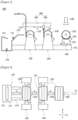
- Figure 1 schematically illustrates a side arrangement diagram of a pouch roll replacement system according to one example of the present invention
- Figure 2 schematically illustrates a plan arrangement diagram of a pouch roll replacement system according to one example of the present invention.
- the pouch roll replacement system (100) related to one example of the present invention comprises an unwinder chucking part (130), a replacement chucking part (140), a transport part (150), a measuring part (160), and a control part (190).
- the transport part (150) is provided to transport a replacement pouch roll (120) along a transport direction (M, x-axis direction in Figure 1 ).
- the transport part (150) transports the replacement pouch roll (120) to the replacement chucking part (140).
- the transport part (150) transports the chuck-released replacement pouch roll (120) to the unwinder chucking part (130).
- the y-axis direction represents the chucking and chuck-release direction performed in the chucking parts (130, 140), and the y-axis direction may be orthogonal to the transport direction (M).
- the unwinder chucking part (130) chucks a traveling pouch roll and a replacement pouch roll and unwinds the pouch wound around the chucked pouch roll, thereby performing a function of supplying pouches to the battery manufacturing process.
- the ⁇ traveling pouch roll (110)' means a pouch roll chucked to the unwinder chucking part (130) to supply a pouch (115) to the battery manufacturing process.
- the ⁇ replacement pouch roll (120)' means a pouch roll newly chucked to the unwinder chucking part (130) when the use of the traveling pouch roll (110) chucked to the unwinder chucking part (130) is completed.
- the traveling pouch roll (110) and the replacement pouch roll (120) comprise roll cores and pouches (115, 125) wound around the roll cores, respectively, where each pouch roll (110, 120) may have a cylindrical shape.
- the roll core has a central axis, and the central axes of the traveling and replacement pouch rolls (110, 120) are chucked to the respective chucking parts (130, 140).
- each chucking part (130, 140) has a predetermined chucking height, where the chucking height may be a height (z-axis direction in Figure 1 ) based on the bottom surface of the installation space on which the chucking part is installed.
- the unwinder chucking part (130) chucks the replacement pouch roll (120) seated on the transport part (150), and upon chucking, the central axis height of the replacement pouch roll (120) seated on the transport part (150) must be the same as the chucking height of the unwinder chucking part (130).
- the central axis height of the replacement pouch roll (120) may be a height (z-axis direction in Figure 1 ) based on the bottom surface of the installation space where the transport part (150) is installed.
- the central axis height of the replacement pouch roll (120) seated on the transport part (150) varies.
- the central axis height of the replacement pouch roll (120) must be adjusted to be the same as the chucking height of the unwinder chucking part (130) before being chucked.
- the replacement chucking part (140) is provided to chuck the replacement pouch roll (120).
- the replacement chucking part (140) has a predetermined chucking height, where the chucking height may be a height based on the bottom surface of the installation space on which the chucking part (140) is installed.
- the replacement chucking part (140) chucks the replacement pouch roll (120) seated on the transport part (150), and upon chucking, the central axis height of the replacement pouch roll (120) seated on the transport part (150) must be the same as the chucking height of the replacement chucking part (140).
- the central axis height of the replacement pouch roll (120) may be a height based on the bottom surface of the installation space where the transport part (150) is installed.
- the central axis height of the replacement pouch roll (120) seated on the transport part (150) varies.
- the central axis height of the replacement pouch roll (120) must be adjusted to be the same as the chucking height of the replacement chucking part (140) before being chucking.
- Figure 3 schematically illustrates a configuration diagram of a pouch roll replacement system according to one example of the present invention
- Figure 4 is a diagram for explaining a process for correcting a height of a replacement pouch roll in one example of the present invention.
- the pouch roll replacement system (100) related to one example of the present invention may automatically correct the height (h1) of the replacement pouch roll (120) so that the central axis height of the replacement pouch roll (120) matches the chucking height of the replacement chucking part (140) and the central axis height of the traveling pouch roll (110) chucked to the unwinder chucking part (130).
- the chucking height of the replacement chucking part (140) may be provided to be the same as the chucking height (h0) of the unwinder chucking part (130). That is, the unwinder chucking part (130) may have the same chucking height as that of the replacement chucking part (140), and the transport part (150) may be provided to transport the replacement pouch roll (120) from the replacement chucking part (140) to the unwinder chucking part (130).
- the traveling pouch roll (110) and the replacement pouch roll (120) may be aluminum (AL) pouch rolls used in a packaging (PKG) process.
- the pouch roll replacement system (100) comprises a transport part (150) transporting a replacement pouch roll (120) and capable of adjusting the central axis height (h1) of the replacement pouch roll (120), and a replacement chucking part (140) provided to chuck the replacement pouch roll (120) transported through the transport part (150) and having a predetermined chucking height.
- the pouch roll replacement system (100) comprises an unwinder chucking part (130) with a traveling pouch roll (110) installed, a measuring part (160) measuring the distance to the replacement pouch roll (120) seated on the transport part (150) before transporting the replacement pouch roll (120) to the replacement chucking part (140), and a control part (190) controlling the transport part (150) so that the central axis height (h1) of the replacement pouch roll (120) seated on the transport part (150) is adjusted based on the measurement information of the measuring part (160) and the chucking height of the replacement chucking part (140).
- the pouch roll replacement system (100) may further comprise a pouch connection part (180) gripping the end of the pouch wound around the replacement pouch roll (120) chucked to the replacement chucking part (140), and then transferring the end of the pouch toward the unwinder chucking part (130).
- control part (190) may chuck-release the replacement pouch roll (120) from the replacement chucking part (140), and then transport the replacement pouch (120) to the unwinder chucking part (130) through the transport part (150).
- the pouch roll replacement system (100) may further comprise a roll core recovery part (170) recovering the roll core of the traveling pouch roll (110) chuck-released from the unwinder chucking part (130).
- the control part (190) controls the operation of the unwinder chucking part (130), the replacement chucking part (140), the measuring part (160), and the pouch connection part (180).
- control part (190) may control the operation of the transport part (150) so that the central axis height of the replacement pouch roll (120) seated on the transport part (150) is adjusted, and then the replacement pouch roll (120) is transported to the replacement chucking part (140).
- control part (190) may be provided so that it calculates the diameter of the replacement pouch roll (120) based on the measurement information of the measuring part, and, calculates the difference between the chucking height of the replacement chucking part (140) and the central axis height of the replacement pouch roll (120) seated on the transport part (150) based on the diameter of the replacement pouch roll (120).
- control part (190) may calculate the difference between the chucking height of the replacement chucking part (140) and the central axis height of the replacement pouch roll seated on the transport part (150) as a height correction value, and may control the transport part (150) so that the central axis height of the replacement pouch roll (120) seated on the transport part (150) is adjusted by the height correction value.
- control part (190) may adjust the central axis height of the replacement pouch roll (120) seated on the transport part so that the central axis height of the replacement pouch roll (120) seated on the transport part (150) matches the chucking height of the replacement chucking part.
- the measuring part (160) may comprise a distance sensor measuring the distance from the replacement pouch roll (120) seated on the transport part (150), and the distance sensor may be an ultrasonic sensor.
- the measuring part (160) may be provided to measure the distance from the replacement pouch roll (120) seated on the transport part (150) before the replacement pouch roll (120) is transported to the replacement chucking part (140).
- the measuring part (160) is provided to measure the distance from the replacement pouch roll (120) at the reference position of the transport part (150) (also referred to as the ⁇ transport standby position'). At this time, distance information according to the diameter of the replacement pouch roll (120) may be stored in advance in the control part (190), and as the measuring part (160) measures the distance from the replacement pouch roll (120), and the control part (190) compares the measured distance with the pre-stored distance information, it is possible to calculate the diameter of the replacement pouch roll (120).
- control part (190) may calculate the central axis height (h1) of the replacement pouch roll (120) seated on the transport part (150) based on the height information of the transport part (150) and the diameter information of the replacement pouch roll (120) at the reference position.
- the chucking heights of the replacement chucking part (140) and the unwinder chucking part (130) are each stored, and the control part (190) adjusts the central axis height of the replacement pouch roll (120) seated on the transport part (150) so that the central axis height of the replacement pouch roll (120) seated on the transport part (150) matches the chucking height of the replacement chucking part.
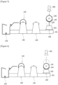
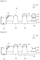
- Figures 5 to 7 are diagrams for explaining operating states of a transport part (150) in a pouch roll replacement system according to one example of the present invention.
- the pouch roll replacement system (100) comprises an unwinder chucking part (130), a replacement chucking part (140), a transport part (150), a measuring part (160), and a roll core recovery part (170), a pouch connection part (180), and a control part (190).
- the unwinder chucking part (130) is provided in an unwinder of a secondary battery manufacturing process.
- the traveling pouch roll (110) is rotatably installed in the unwinder chucking part (130) so that the pouch (115) wound around the traveling pouch roll (110) can be unwound.
- the replacement chucking part (140) is a device in which the replacement pouch roll (120) is chucked.
- the replacement pouch roll (120) is sequentially transported to the replacement chucking part (140) and the unwinder chucking part (130) through the transport part (150).
- the replacement chucking part (140) may have the same chucking height as the chucking height of the unwinder chucking part (130) in the transport path (M, x-axis direction) of the transport part (150), and may be disposed in line with the unwinder chucking part (130).
- the transport part (150) sequentially transports the replacement pouch roll (120) to the replacement chucking part (140) and the unwinder chucking part (130).
- the transport part (150) comprises a transport rail (151), a shuttle (153), and a height adjustment unit (155).
- the transport part (150) may comprise a transport rail (151) extending to guide the transport of the replacement pouch roll (120) through the replacement chucking part (140) to the unwinder chucking part (130), a shuttle (153) including a seating member (154), on which the replacement pouch roll (120) is seated, and provided to be movable along the transport rail (151), and a height adjustment unit (155) adjusting the height of the seating member (154).
- the transport rail (151) forms a transport path (x-axis direction) that guides transport of the replacement pouch roll (120) to the unwinder chucking part (130).
- the shuttle (153) is installed on the transport rail (151) to be capable of reciprocating.
- the shuttle (153) is installed to be capable of reciprocating along the transport rail (151) back and forth.
- the shuttle (153) is moved at the transport standby position (P0) of the transport part (150) to the unwinder chucking part (130).
- the shuttle (153) is operated to return to the transport standby position (P0) from the unwinder chucking part (130).
- the shuttle (153) is provided with the seating member (154).
- the replacement pouch roll (120) is seated on the seating member (154).
- the seating member (154) may have a shape curved with a predetermined curvature in order to stably support the replacement pouch roll (120), and for example, the seating member (154) may have an arc-shaped cross section.
- the height adjustment unit (155) is coupled to the seating member (154).
- the height adjustment unit (155) is installed on the shuttle (153) to perform a function of adjusting the height of the seating member (154).
- the height adjustment unit (155) may comprise a servo motor.
- the operation of the height adjustment unit (155) is controlled by the control part (190).
- the height adjustment unit (155) may adjust the central axis height of the replacement pouch roll (120) along the height direction (z-axis direction shown in Figure 1 ) by the height correction value ( ⁇ h) calculated by the control part (190).
- the measuring part (160) measures the distance to the replacement pouch roll (120) at the transport standby position (P0).
- the measuring part (160) comprises a distance sensor measuring the vertical distance from the replacement pouch roll (120) seated on the transport part (150) at the transport standby position (P0).
- An ultrasonic sensor may be used as the distance sensor.
- the transport standby position (P0) is a position where the transport part (150) is during standby in a state where the measuring part (160) is installed and the replacement pouch roll (120) is seated, which may be a fixed position.
- the transport part (150) may be located at the bottom of the measuring part (160).
- control part (190) may control the operation of the transport part (150) so that the central axis height of the replacement pouch roll (120) matches the central axis height of the traveling pouch roll (110) chucked on the unwinder chucking part (130) based on the measurement information of the measuring part (160).
- the central axis height (also referred to as the ⁇ chucking height') of the traveling pouch roll (110) may be preset in the control part (190) as the reference height (h 0 ).
- the control part (190) may receive the measured distance information to calculate the diameter of the replacement pouch roll (120), which calculates the central axis height (h 1 ) of the replacement pouch roll (120) based on the diameter information of the replacement pouch roll (120).
- the control part (190) may calculate a height correction value ( ⁇ h) which is the difference between the chucking height (h 0 ) and the central axis height (h 1 ) of the replacement pouch roll (120). Then, the control part (190) controls the operation of the transport part (150) so that the central axis height of the replacement pouch roll (120) is corrected by the height correction value ( ⁇ h).
- ⁇ h the height correction value
- the pouch connection part (180) may comprise a guide bar (181) extending from the upper part of the replacement chucking part (140) to the upper part of the unwinder chucking part (130), and a gripper (183) installed to be movable along the guide bar (181) and holding the end of the pouch (125) wound around the replacement pouch roll (120) to move from the replacement chucking part (140) toward the unwinder chucking part (130).
- the guide bar (181) is installed parallel to the transport path (M) of the transport part (150) at the upper part of the unwinder chucking part (130) and the replacement chucking part (140).
- the gripper (183) is installed on the guide bar (181) to be capable of reciprocating back and forth.
- the gripper (183) holds the end of the pouch (125) wound around the replacement pouch roll (120) to move forward from the replacement chucking part (140) toward the unwinder chucking part (130).
- the roll core recovery part (170) is installed adjacent to the unwinder chucking part (130) in the transport path of the transport part (150).
- the roll core recovery part (170) recovers the roll core (111) of the traveling pouch roll (110) chuck-released from the chucking in the unwinder chucking part (130).
- the roll core recovery part (170) may comprise a roll core guide member (171) and a roll core recovery container (173).
- the roll core guide member (171) may be connected to the unwinder chucking part (130), and the roll core guide member (171) may be installed parallel to the transport rail (151).
- the roll core (111) of the traveling pouch roll (110) chuck-released from the unwinder chucking part (130) is recovered into the roll core recovery container (173) along the roll core guide member (171).
- Figures 5 to 8 are diagrams for explaining operating states of a transport part in a pouch roll replacement system according to one example of the present invention.
- the central axis height of the traveling pouch roll (110) chucked in the unwinder chucking part (130) is preset to the reference height (h 0 ).
- the chucking height of the unwinder chucking part (130) is a fixed height
- the chucking height of the unwinder chucking part (130) is the same as the chucking height of the replacement chucking part (140).
- the chucking height of the unwinder chucking part (130) corresponds to the central axis height of the traveling pouch roll (110).
- the replacement pouch roll (120) is supplied to the transport part (150).
- the transport part (150) is located at the transport standby position (P0). At the transport standby position, the replacement pouch roll (120) is in a state of being seated on the seating member (154).
- the central axis height of the replacement pouch roll (120) is measured as the measurement height (h 1 ).
- the measuring part (160) measures the distance to the replacement pouch roll (120) at the transport standby position (P0). At the transport standby position (P0), the measuring part (160) and the transport part (150) are disposed up and down.
- control part (190) calculates the central axis height of the replacement pouch roll (120) as the measurement height (h 1 ), based on the measurement information.
- control part (190) may calculate a height correction value ( ⁇ h) of the replacement pouch roll (120) with respect to the traveling pouch roll (110).
- the height correction value ( ⁇ h) is the difference value between the reference height (h 0 ) and the measurement height (h 1 ).
- control part (190) controls the operation of the transport part (150) so that the central axis height of the replacement pouch roll (120) matches the reference height (h 0 ) based on the height correction value ( ⁇ h) information.
- the height adjustment unit (155) adjusts the central axis height of the replacement pouch roll (120) by the height correction value ( ⁇ h). Through this process, the central axis height of the replacement pouch roll (120) seated on the transport part (150) is matched to the reference height (h 0 ).
- the replacement pouch roll (120) is transported at the transport standby position (P0) to the replacement chucking part (140) by the transport part (150).
- the replacement pouch roll (120) is chucked to the replacement chucking part (140) in a state of being seated on the transport part (150).
- the replacement pouch roll (120) chucked to the replacement chucking part (140) is chuck-released, and the replacement pouch roll (120) is separated from the replacement chucking part (140).
- the replacement pouch roll (120) separated from the replacement chucking part (140) is transported to the unwinder chucking part (130) by the transport part (150).
- the unwinder chucking part (130) is operated to chuck-release the traveling pouch roll (110).
- the used traveling pouch roll (110) is recovered from the unwinder chucking part (130) to the roll core recovery part (170).
- the pouch roll replacement system according to one example of the present invention, and the pouch roll position correction method using the same, by measuring the roll diameter of the replacement pouch roll seated on the transport part before transporting the replacement pouch to the replacement chucking part, it is possible to adjust the central axis height of the replacement pouch roll seated on the transport part to the chucking heights of the replacement chucking part and the unwinder chucking part.
Landscapes
- Chemical & Material Sciences (AREA)
- Chemical Kinetics & Catalysis (AREA)
- Electrochemistry (AREA)
- General Chemical & Material Sciences (AREA)
- Engineering & Computer Science (AREA)
- Manufacturing & Machinery (AREA)
- Replacement Of Web Rolls (AREA)
Abstract
Description
- The present invention relates to a pouch roll replacement system and a pouch roll position correction method using the same, and specifically, relates to a pouch roll replacement system capable of matching a central axis height of a replacement pouch roll before transport to chucking heights of a replacement chucking part and an unwinder chucking part, and a pouch roll position correction method thereof.
- This application claims the benefit of priority based on
Korean Patent Application No. 10-2022-0072001 dated June 14, 2022 - Lithium secondary batteries, which can be charged and discharged, are also used as an energy source for electric vehicles, hybrid electric vehicles, and the like, which are presented as an alternative to existing gasoline and diesel vehicles that cause air pollution.
- In the lithium secondary batteries, a positive electrode and a negative electrode are laminated with a separator interposed therebetween, where charging and discharging can be repeatedly performed while lithium ions move between the positive electrode and the negative electrode.
- In the case of a pouch-type secondary battery, after manufacturing an electrode assembly in which positive electrodes, separators, and negative electrodes are cross-laminated, the electrode assembly is accommodated in a pouch. That is, the pouch is used as a case that forms the exterior of the secondary battery.
- In a secondary battery manufacturing process, the pouch is supplied in a roll-to-roll manner. However, when the entire pouch roll wound in the form of a roll is used up, a worker stops the equipment, connects the end of the pouch wound around the pouch roll during use to the end of the pouch wound around a new pouch roll with a tape, and then restarts the equipment.
- While the pouch roll is chucked to an unwinder, and the pouch wound around the pouch roll is unwound by the unwinder, the pouch is supplied to the battery manufacturing process.
- Meanwhile, when the roll diameter of the replacement pouch roll supplied to the unwinder varies, the chucking height of the pouch roll may vary, where conventionally, a worker has manually adjusted the standby height of the replacement pouch roll up to the chucking height.
- In general, pouch rolls are difficult to transport as they weigh approximately 200 kg or more, and there is a risk that safety accidents occur when the pouch roll falls.
- In addition, conventionally, upon pouch roll replacement, the equipment had to be shut down, and there was a problem that the workload of the worker was caused due to frequent replacement.
- The present invention is intended to provide a pouch roll replacement system capable of adjusting a chucking height of a replacement pouch roll according to the diameter of the replacement pouch roll, and a pouch roll position correction method using the same.
- In addition, the present invention is intended to provide a pouch roll replacement system capable of adjusting a central axis height of a replacement pouch roll before transport to chucking heights of a replacement chucking part and an unwinder chucking part, even if the roll diameter is different for each replacement pouch roll, and a pouch roll position correction method using the same.
- In order to solve the above problem, a pouch roll replacement system according to one example of the present invention comprises a transport part transporting a replacement pouch roll and capable of adjusting the central axis height of the replacement pouch roll, a replacement chucking part provided to chuck the replacement pouch roll transported through the transport part and having a predetermined chucking height, an unwinder chucking part with a traveling pouch roll installed, a measuring part measuring the distance to the replacement pouch roll seated on the transport part before transporting the replacement pouch roll to the replacement chucking part, and a control part controlling the transport part so that the central axis height of the replacement pouch roll seated on the transport part is adjusted based on the measurement information of the measuring part and the chucking height of the replacement chucking part.
- Also, the control part may be provided to control the operation of the transport part so that the replacement pouch roll is transported to the replacement chucking part after adjusting the central axis height of the replacement pouch roll seated on the transport part.
- In addition, the control part may be provided so that it calculates the diameter of the replacement pouch roll based on the measurement information, and calculates the difference between the chucking height of the replacement chucking part and the center axis height of the replacement pouch roll seated on the transport part based on the diameter of the replacement pouch roll.
- Furthermore, the control part may calculate the difference between the chucking height of the replacement chucking part and the central axis height of the replacement pouch roll seated on the transport part as a height correction value, and may control the transport part so that the central axis height of the replacement pouch roll seated on the transport part is adjusted by the height correction value.
- Also, the control part may adjust the central axis height of the replacement pouch roll seated on the transport part so that the central axis height of the replacement pouch roll seated on the transport part matches the chucking height of the replacement chucking part.
- In addition, the unwinder chucking part may have the same chucking height as that of the replacement chucking part, and the transport part may be provided to transport the replacement pouch roll from the replacement chucking part to the unwinder chucking part.
- Furthermore, the transport part may comprise a transport rail extending to guide the transport of the replacement pouch roll through the replacement chucking part to the unwinder chucking part, a shuttle including a seating member, on which the replacement pouch roll is seated, and provided to be movable along the transport rail, and a height adjustment unit adjusting the height of the seating member.
- Also, the shuttle may be provided to be capable of reciprocating along the transport rail. In addition, the shuttle may be provided so that when the traveling pouch roll is replaced with the replacement pouch roll, it is moved to the unwinder chucking part, and after the replacement pouch roll is chucked to the unwinder chucking part, it moves from the unwinder chucking part to the measuring part.
- Furthermore, the seating member may be curved to a predetermined curvature.
- Also, the measuring part may comprise a distance sensor measuring the distance from the replacement pouch roll seated on the transport part.
- In addition, the distance sensor may be an ultrasonic sensor.
- Furthermore, the pouch roll replacement system may further comprise a pouch connection part gripping the end of the pouch wound around the replacement pouch roll chucked to the replacement chucking part, and then transferring the end of the pouch toward the unwinder chucking part.
- Also, the pouch connection part may comprise a guide bar extending from the upper part of the replacement chucking part to the upper part of the unwinder chucking part, and a gripper installed to be movable along the guide bar and holding the end of the pouch wound around the replacement pouch roll to move from the replacement chucking part toward the unwinder chucking part.
- In addition, when the end of the pouch is gripped through the pouch connection part, the control part may chuck-release the replacement pouch roll from the replacement chucking part, and then transport the replacement pouch roll to the unwinder chucking part through the transport part.
- Furthermore, the pouch roll replacement system may further comprise a roll core recovery part recovering the roll core of the traveling pouch roll chuck-released from the unwinder chucking part.
- As discussed above, the pouch roll replacement system according to one example of the present invention, and the pouch roll position correction method using the same have the following effects.
- By measuring the roll diameter of the replacement pouch roll seated on the transport part, it is possible to adjust the central axis height of the replacement pouch roll seated on the transport part to the chucking heights of the replacement chucking part and the unwinder chucking part before transporting the replacement pouch to the replacement chucking part.
- Also, it is possible to automatically correct the position (height) of the replacement pouch roll seated on the transport part so that the central axis height of the replacement pouch roll matches the chucking height of the traveling pouch roll.
- In addition, even if the roll diameter is different for each replacement pouch roll, the roll diameter is measured for each replacement pouch roll seated on the transport part, and thus, the height of the replacement pouch roll is automatically corrected so that the central axis height of the replacement pouch roll matches the central axis height of the traveling pouch roll, whereby it is possible to automatically supply the replacement pouch roll to the replacement chucking part and the unwinder chucking part.
-
-
Figure 1 schematically illustrates a side arrangement diagram of a pouch roll replacement system according to one example of the present invention. -
Figure 2 schematically illustrates a plan arrangement diagram of a pouch roll replacement system according to one example of the present invention. -
Figure 3 schematically illustrates a configuration diagram of a pouch roll replacement system according to one example of the present invention. -
Figure 4 is a diagram for explaining a process for correcting a height of a replacement pouch roll in one example of the present invention. -
Figures 5 to 8 are diagrams for explaining operating states of a transport part in a pouch roll replacement system according to one example of the present invention. - Hereinafter, a pouch roll replacement system according to one example of the present invention, and a pouch roll position correction method using the same will be described in detail with reference to the drawings.
- In addition, regardless of the reference numerals, the same or corresponding components are given by the same or similar reference numerals, duplicate descriptions thereof will be omitted, and for convenience of explanation, the size and shape of each component member as shown can be exaggerated or reduced.
-
Figure 1 schematically illustrates a side arrangement diagram of a pouch roll replacement system according to one example of the present invention, andFigure 2 schematically illustrates a plan arrangement diagram of a pouch roll replacement system according to one example of the present invention. - The pouch roll replacement system (100) related to one example of the present invention comprises an unwinder chucking part (130), a replacement chucking part (140), a transport part (150), a measuring part (160), and a control part (190).
- Referring to
Figures 1 and 2 , the transport part (150) is provided to transport a replacement pouch roll (120) along a transport direction (M, x-axis direction inFigure 1 ). The transport part (150) transports the replacement pouch roll (120) to the replacement chucking part (140). In addition, when chucking and chuck-release are performed in the replacement chucking part (140), the transport part (150) transports the chuck-released replacement pouch roll (120) to the unwinder chucking part (130). - Referring to
Figure 2 , the y-axis direction represents the chucking and chuck-release direction performed in the chucking parts (130, 140), and the y-axis direction may be orthogonal to the transport direction (M). - The unwinder chucking part (130) chucks a traveling pouch roll and a replacement pouch roll and unwinds the pouch wound around the chucked pouch roll, thereby performing a function of supplying pouches to the battery manufacturing process.
- In this document, the `traveling pouch roll (110)' means a pouch roll chucked to the unwinder chucking part (130) to supply a pouch (115) to the battery manufacturing process. In addition, the `replacement pouch roll (120)' means a pouch roll newly chucked to the unwinder chucking part (130) when the use of the traveling pouch roll (110) chucked to the unwinder chucking part (130) is completed.
- Also, the traveling pouch roll (110) and the replacement pouch roll (120) comprise roll cores and pouches (115, 125) wound around the roll cores, respectively, where each pouch roll (110, 120) may have a cylindrical shape. At this instance, the roll core has a central axis, and the central axes of the traveling and replacement pouch rolls (110, 120) are chucked to the respective chucking parts (130, 140). At this time, each chucking part (130, 140) has a predetermined chucking height, where the chucking height may be a height (z-axis direction in
Figure 1 ) based on the bottom surface of the installation space on which the chucking part is installed. - In addition, the unwinder chucking part (130) chucks the replacement pouch roll (120) seated on the transport part (150), and upon chucking, the central axis height of the replacement pouch roll (120) seated on the transport part (150) must be the same as the chucking height of the unwinder chucking part (130). At this time, the central axis height of the replacement pouch roll (120) may be a height (z-axis direction in
Figure 1 ) based on the bottom surface of the installation space where the transport part (150) is installed. - If the roll diameter is different for each newly supplied replacement pouch roll (120), the central axis height of the replacement pouch roll (120) seated on the transport part (150) varies. At this instance, since the unwinder chucking part (130) has a fixed chucking height, the central axis height of the replacement pouch roll (120) must be adjusted to be the same as the chucking height of the unwinder chucking part (130) before being chucked.
- In addition, before the replacement pouch roll (120) is transported to the unwinder chucking part (130), the replacement chucking part (140) is provided to chuck the replacement pouch roll (120). At this time, the replacement chucking part (140) has a predetermined chucking height, where the chucking height may be a height based on the bottom surface of the installation space on which the chucking part (140) is installed.
- The replacement chucking part (140) chucks the replacement pouch roll (120) seated on the transport part (150), and upon chucking, the central axis height of the replacement pouch roll (120) seated on the transport part (150) must be the same as the chucking height of the replacement chucking part (140). As described above, the central axis height of the replacement pouch roll (120) may be a height based on the bottom surface of the installation space where the transport part (150) is installed.
- If the roll diameter is different for each replacement pouch roll (120) newly supplied in the battery manufacturing process, the central axis height of the replacement pouch roll (120) seated on the transport part (150) varies. At this time, since the replacement chucking part (140) has a fixed chucking height, the central axis height of the replacement pouch roll (120) must be adjusted to be the same as the chucking height of the replacement chucking part (140) before being chucking.
- Referring to
Figure 1 , when a replacement pouch (120) is chucked to the replacement chucking part (140), the work of connecting the end of the pouch (125) wound around the replacement pouch roll (120) and the end of the pouch (115) being supplied to the battery manufacturing process is performed. -
Figure 3 schematically illustrates a configuration diagram of a pouch roll replacement system according to one example of the present invention, andFigure 4 is a diagram for explaining a process for correcting a height of a replacement pouch roll in one example of the present invention. - The pouch roll replacement system (100) related to one example of the present invention may automatically correct the height (h1) of the replacement pouch roll (120) so that the central axis height of the replacement pouch roll (120) matches the chucking height of the replacement chucking part (140) and the central axis height of the traveling pouch roll (110) chucked to the unwinder chucking part (130).
- Also, in this document, the chucking height of the replacement chucking part (140) may be provided to be the same as the chucking height (h0) of the unwinder chucking part (130). That is, the unwinder chucking part (130) may have the same chucking height as that of the replacement chucking part (140), and the transport part (150) may be provided to transport the replacement pouch roll (120) from the replacement chucking part (140) to the unwinder chucking part (130).
- In addition, in this document, the traveling pouch roll (110) and the replacement pouch roll (120) may be aluminum (AL) pouch rolls used in a packaging (PKG) process.
- The pouch roll replacement system (100) according to one example of the present invention comprises a transport part (150) transporting a replacement pouch roll (120) and capable of adjusting the central axis height (h1) of the replacement pouch roll (120), and a replacement chucking part (140) provided to chuck the replacement pouch roll (120) transported through the transport part (150) and having a predetermined chucking height.
- Also, the pouch roll replacement system (100) comprises an unwinder chucking part (130) with a traveling pouch roll (110) installed, a measuring part (160) measuring the distance to the replacement pouch roll (120) seated on the transport part (150) before transporting the replacement pouch roll (120) to the replacement chucking part (140), and a control part (190) controlling the transport part (150) so that the central axis height (h1) of the replacement pouch roll (120) seated on the transport part (150) is adjusted based on the measurement information of the measuring part (160) and the chucking height of the replacement chucking part (140).
- In addition, the pouch roll replacement system (100) may further comprise a pouch connection part (180) gripping the end of the pouch wound around the replacement pouch roll (120) chucked to the replacement chucking part (140), and then transferring the end of the pouch toward the unwinder chucking part (130).
- Furthermore, when the end of the pouch is gripped through the pouch connection part (180), the control part (190) may chuck-release the replacement pouch roll (120) from the replacement chucking part (140), and then transport the replacement pouch (120) to the unwinder chucking part (130) through the transport part (150).
- Also, the pouch roll replacement system (100) may further comprise a roll core recovery part (170) recovering the roll core of the traveling pouch roll (110) chuck-released from the unwinder chucking part (130).
- The control part (190) controls the operation of the unwinder chucking part (130), the replacement chucking part (140), the measuring part (160), and the pouch connection part (180).
- Also, the control part (190) may control the operation of the transport part (150) so that the central axis height of the replacement pouch roll (120) seated on the transport part (150) is adjusted, and then the replacement pouch roll (120) is transported to the replacement chucking part (140).
- In addition, the control part (190) may be provided so that it calculates the diameter of the replacement pouch roll (120) based on the measurement information of the measuring part, and, calculates the difference between the chucking height of the replacement chucking part (140) and the central axis height of the replacement pouch roll (120) seated on the transport part (150) based on the diameter of the replacement pouch roll (120).
- Furthermore, the control part (190) may calculate the difference between the chucking height of the replacement chucking part (140) and the central axis height of the replacement pouch roll seated on the transport part (150) as a height correction value, and may control the transport part (150) so that the central axis height of the replacement pouch roll (120) seated on the transport part (150) is adjusted by the height correction value.
- Also, the control part (190) may adjust the central axis height of the replacement pouch roll (120) seated on the transport part so that the central axis height of the replacement pouch roll (120) seated on the transport part (150) matches the chucking height of the replacement chucking part.
- In addition, the measuring part (160) may comprise a distance sensor measuring the distance from the replacement pouch roll (120) seated on the transport part (150), and the distance sensor may be an ultrasonic sensor.
- Referring to
Figure 4 , the measuring part (160) may be provided to measure the distance from the replacement pouch roll (120) seated on the transport part (150) before the replacement pouch roll (120) is transported to the replacement chucking part (140). - Also, the measuring part (160) is provided to measure the distance from the replacement pouch roll (120) at the reference position of the transport part (150) (also referred to as the `transport standby position'). At this time, distance information according to the diameter of the replacement pouch roll (120) may be stored in advance in the control part (190), and as the measuring part (160) measures the distance from the replacement pouch roll (120), and the control part (190) compares the measured distance with the pre-stored distance information, it is possible to calculate the diameter of the replacement pouch roll (120).
- In addition, the control part (190) may calculate the central axis height (h1) of the replacement pouch roll (120) seated on the transport part (150) based on the height information of the transport part (150) and the diameter information of the replacement pouch roll (120) at the reference position.
- Furthermore, in the control part (190), the chucking heights of the replacement chucking part (140) and the unwinder chucking part (130) are each stored, and the control part (190) adjusts the central axis height of the replacement pouch roll (120) seated on the transport part (150) so that the central axis height of the replacement pouch roll (120) seated on the transport part (150) matches the chucking height of the replacement chucking part.
-
Figures 5 to 7 are diagrams for explaining operating states of a transport part (150) in a pouch roll replacement system according to one example of the present invention. - The pouch roll replacement system (100) according to one example of the present invention comprises an unwinder chucking part (130), a replacement chucking part (140), a transport part (150), a measuring part (160), and a roll core recovery part (170), a pouch connection part (180), and a control part (190).
- The unwinder chucking part (130) is provided in an unwinder of a secondary battery manufacturing process. The traveling pouch roll (110) is rotatably installed in the unwinder chucking part (130) so that the pouch (115) wound around the traveling pouch roll (110) can be unwound.
- Also, the replacement chucking part (140) is a device in which the replacement pouch roll (120) is chucked. In this example, the replacement pouch roll (120) is sequentially transported to the replacement chucking part (140) and the unwinder chucking part (130) through the transport part (150).
- In addition, the replacement chucking part (140) may have the same chucking height as the chucking height of the unwinder chucking part (130) in the transport path (M, x-axis direction) of the transport part (150), and may be disposed in line with the unwinder chucking part (130).
- The transport part (150) sequentially transports the replacement pouch roll (120) to the replacement chucking part (140) and the unwinder chucking part (130). The transport part (150) comprises a transport rail (151), a shuttle (153), and a height adjustment unit (155).
- Specifically, the transport part (150) may comprise a transport rail (151) extending to guide the transport of the replacement pouch roll (120) through the replacement chucking part (140) to the unwinder chucking part (130), a shuttle (153) including a seating member (154), on which the replacement pouch roll (120) is seated, and provided to be movable along the transport rail (151), and a height adjustment unit (155) adjusting the height of the seating member (154).
- In addition, the transport rail (151) forms a transport path (x-axis direction) that guides transport of the replacement pouch roll (120) to the unwinder chucking part (130). The shuttle (153) is installed on the transport rail (151) to be capable of reciprocating.
- The shuttle (153) is installed to be capable of reciprocating along the transport rail (151) back and forth. When the traveling pouch roll (110) is replaced with the replacement pouch roll (120), the shuttle (153) is moved at the transport standby position (P0) of the transport part (150) to the unwinder chucking part (130).
- Then, when the replacement pouch roll (120) is chucked to the unwinder chucking part (130), the shuttle (153) is operated to return to the transport standby position (P0) from the unwinder chucking part (130).
- The shuttle (153) is provided with the seating member (154). The replacement pouch roll (120) is seated on the seating member (154). The seating member (154) may have a shape curved with a predetermined curvature in order to stably support the replacement pouch roll (120), and for example, the seating member (154) may have an arc-shaped cross section.
- In addition, the height adjustment unit (155) is coupled to the seating member (154). The height adjustment unit (155) is installed on the shuttle (153) to perform a function of adjusting the height of the seating member (154). The height adjustment unit (155) may comprise a servo motor.
- The operation of the height adjustment unit (155) is controlled by the control part (190). The height adjustment unit (155) may adjust the central axis height of the replacement pouch roll (120) along the height direction (z-axis direction shown in
Figure 1 ) by the height correction value (Δh) calculated by the control part (190). - In addition, the measuring part (160) measures the distance to the replacement pouch roll (120) at the transport standby position (P0). The measuring part (160) comprises a distance sensor measuring the vertical distance from the replacement pouch roll (120) seated on the transport part (150) at the transport standby position (P0). An ultrasonic sensor may be used as the distance sensor.
- In this example, the transport standby position (P0) is a position where the transport part (150) is during standby in a state where the measuring part (160) is installed and the replacement pouch roll (120) is seated, which may be a fixed position.
- Also, at the transport standby position (P0), the transport part (150) may be located at the bottom of the measuring part (160).
- In addition, the control part (190) may control the operation of the transport part (150) so that the central axis height of the replacement pouch roll (120) matches the central axis height of the traveling pouch roll (110) chucked on the unwinder chucking part (130) based on the measurement information of the measuring part (160).
- As described above, the central axis height (also referred to as the `chucking height') of the traveling pouch roll (110) may be preset in the control part (190) as the reference height (h0). The control part (190) may receive the measured distance information to calculate the diameter of the replacement pouch roll (120), which calculates the central axis height (h1) of the replacement pouch roll (120) based on the diameter information of the replacement pouch roll (120).
- Referring to
Figure 4 , the control part (190) may calculate a height correction value (Δh) which is the difference between the chucking height (h0) and the central axis height (h1) of the replacement pouch roll (120). Then, the control part (190) controls the operation of the transport part (150) so that the central axis height of the replacement pouch roll (120) is corrected by the height correction value (Δh). - In addition, the pouch connection part (180) may comprise a guide bar (181) extending from the upper part of the replacement chucking part (140) to the upper part of the unwinder chucking part (130), and a gripper (183) installed to be movable along the guide bar (181) and holding the end of the pouch (125) wound around the replacement pouch roll (120) to move from the replacement chucking part (140) toward the unwinder chucking part (130).
- The guide bar (181) is installed parallel to the transport path (M) of the transport part (150) at the upper part of the unwinder chucking part (130) and the replacement chucking part (140). The gripper (183) is installed on the guide bar (181) to be capable of reciprocating back and forth.
- The gripper (183) holds the end of the pouch (125) wound around the replacement pouch roll (120) to move forward from the replacement chucking part (140) toward the unwinder chucking part (130).
- In addition, the roll core recovery part (170) is installed adjacent to the unwinder chucking part (130) in the transport path of the transport part (150). The roll core recovery part (170) recovers the roll core (111) of the traveling pouch roll (110) chuck-released from the chucking in the unwinder chucking part (130).
- The roll core recovery part (170) may comprise a roll core guide member (171) and a roll core recovery container (173). The roll core guide member (171) may be connected to the unwinder chucking part (130), and the roll core guide member (171) may be installed parallel to the transport rail (151). The roll core (111) of the traveling pouch roll (110) chuck-released from the unwinder chucking part (130) is recovered into the roll core recovery container (173) along the roll core guide member (171).
-
Figures 5 to 8 are diagrams for explaining operating states of a transport part in a pouch roll replacement system according to one example of the present invention. - Hereinafter, referring to
Figures 5 to 8 , a pouch roll position correction method using the pouch roll replacement system (100) will be described. - In the control part (190), the central axis height of the traveling pouch roll (110) chucked in the unwinder chucking part (130) is preset to the reference height (h0). Here, the chucking height of the unwinder chucking part (130) is a fixed height, and the chucking height of the unwinder chucking part (130) is the same as the chucking height of the replacement chucking part (140). The chucking height of the unwinder chucking part (130) corresponds to the central axis height of the traveling pouch roll (110).
- Referring to
Figure 5 , the replacement pouch roll (120) is supplied to the transport part (150). The transport part (150) is located at the transport standby position (P0). At the transport standby position, the replacement pouch roll (120) is in a state of being seated on the seating member (154). - Referring to
Figure 6 , at the transport standby position, the central axis height of the replacement pouch roll (120) is measured as the measurement height (h1). The measuring part (160) measures the distance to the replacement pouch roll (120) at the transport standby position (P0). At the transport standby position (P0), the measuring part (160) and the transport part (150) are disposed up and down. - At this time, the control part (190) calculates the central axis height of the replacement pouch roll (120) as the measurement height (h1), based on the measurement information.
- Subsequently, the control part (190) may calculate a height correction value (Δh) of the replacement pouch roll (120) with respect to the traveling pouch roll (110). The height correction value (Δh) is the difference value between the reference height (h0) and the measurement height (h1).
- In addition, the control part (190) controls the operation of the transport part (150) so that the central axis height of the replacement pouch roll (120) matches the reference height (h0) based on the height correction value (Δh) information. At this instance, the height adjustment unit (155) adjusts the central axis height of the replacement pouch roll (120) by the height correction value (Δh). Through this process, the central axis height of the replacement pouch roll (120) seated on the transport part (150) is matched to the reference height (h0).
- Referring to
Figure 7 , the replacement pouch roll (120) is transported at the transport standby position (P0) to the replacement chucking part (140) by the transport part (150). The replacement pouch roll (120) is chucked to the replacement chucking part (140) in a state of being seated on the transport part (150). - Upon replacement of the traveling pouch roll (110), the replacement pouch roll (120) chucked to the replacement chucking part (140) is chuck-released, and the replacement pouch roll (120) is separated from the replacement chucking part (140). The replacement pouch roll (120) separated from the replacement chucking part (140) is transported to the unwinder chucking part (130) by the transport part (150).
- In addition, upon replacement of the traveling pouch roll (110), the unwinder chucking part (130) is operated to chuck-release the traveling pouch roll (110). The used traveling pouch roll (110) is recovered from the unwinder chucking part (130) to the roll core recovery part (170).
- Referring to
Figure 8 , when the replacement pouch roll (120) is chucked to the unwinder chucking part (130), the transport part (150) is operated to return from the unwinder chucking part (130) to the transport standby position (P0). - One example of the present invention as described above has been disclosed for illustrative purposes, and those skilled in the art having ordinary knowledge of the present invention will be able to make various modifications, changes, and additions within the spirit and scope of the present invention, and such modifications, changes, and additions should be regarded as falling within the scope of the following claims.
- According to the pouch roll replacement system according to one example of the present invention, and the pouch roll position correction method using the same, by measuring the roll diameter of the replacement pouch roll seated on the transport part before transporting the replacement pouch to the replacement chucking part, it is possible to adjust the central axis height of the replacement pouch roll seated on the transport part to the chucking heights of the replacement chucking part and the unwinder chucking part.
Claims (15)
- A pouch roll replacement system comprising:a transport part transporting a replacement pouch roll and capable of adjusting the central axis height of the replacement pouch roll;a replacement chucking part provided to chuck the replacement pouch roll transported through the transport part and having a predetermined chucking height;an unwinder chucking part with a traveling pouch roll installed;a measuring part measuring the distance to the replacement pouch roll seated on the transport part before transporting the replacement pouch roll to the replacement chucking part; anda control part controlling the transport part so that the central axis height of the replacement pouch roll seated on the transport part is adjusted based on the measurement information of the measuring part and the chucking height of the replacement chucking part.
- The pouch roll replacement system according to claim 1, wherein
the control part controls the operation of the transport part so that the replacement pouch roll is transported to the replacement chucking part after adjusting the central axis height of the replacement pouch roll seated on the transport part. - The pouch roll replacement system according to claim 1, wherein
the control part is provided so that it calculates the diameter of the replacement pouch roll based on the measurement information, and calculates the difference between the chucking height of the replacement chucking part and the center axis height of the replacement pouch roll seated on the transport part based on the diameter of the replacement pouch roll. - The pouch roll replacement system according to claim 3, wherein
the control part calculates the difference between the chucking height of the replacement chucking part and the central axis height of the replacement pouch roll seated on the transport part as a height correction value, and controls the transport part so that the central axis height of the replacement pouch roll seated on the transport part is adjusted by the height correction value. - The pouch roll replacement system according to claim 3, wherein
the control part adjusts the central axis height of the replacement pouch roll seated on the transport part so that the central axis height of the replacement pouch roll seated on the transport part matches the chucking height of the replacement chucking part. - The pouch roll replacement system according to claim 1, whereinthe unwinder chucking part has the same chucking height as that of the replacement chucking part, andthe transport part is provided to transport the replacement pouch roll from the replacement chucking part to the unwinder chucking part.
- The pouch roll replacement system according to claim 6, wherein the transport part comprises:a transport rail extending to guide the transport of the replacement pouch roll through the replacement chucking part to the unwinder chucking part;a shuttle including a seating member, on which the replacement pouch roll is seated, and provided to be movable along the transport rail; anda height adjustment unit adjusting the height of the seating member.
- The pouch roll replacement system according to claim 7, whereinthe shuttle is provided to be capable of reciprocating along the transport rail, andthe shuttle is moved to the unwinder chucking part when the traveling pouch roll is replaced with the replacement pouch roll, and moves from the unwinder chucking part to the measuring part after the replacement pouch roll is chucked to the unwinder chucking part.
- The pouch roll replacement system according to claim 7, wherein
the seating member is curved to a predetermined curvature. - The pouch roll replacement system according to claim 1, wherein
the measuring part comprises a distance sensor measuring the distance from the replacement pouch roll seated on the transport part. - The pouch roll replacement system according to claim 10, wherein
the distance sensor is an ultrasonic sensor. - The pouch roll replacement system according to claim 1, further comprising
a pouch connection part gripping the end of the pouch wound around the replacement pouch roll chucked to the replacement chucking part, and then transferring the end of the pouch toward the unwinder chucking part. - The pouch roll replacement system according to claim 12, wherein the pouch connection part comprisesa guide bar extending from the upper part of the replacement chucking part to the upper part of the unwinder chucking part, anda gripper installed to be movable along the guide bar and holding the end of the pouch wound around the replacement pouch roll to move from the replacement chucking part toward the unwinder chucking part.
- The pouch roll replacement system according to claim 12, wherein
when the end of the pouch is gripped through the pouch connection part, the control part chuck-releases the replacement pouch roll from the replacement chucking part, and then transports the replacement pouch roll to the unwinder chucking part through the transport part. - The pouch roll replacement system according to claim 1, further comprising
a roll core recovery part recovering the roll core of the traveling pouch roll chuck-released from the unwinder chucking part.
Applications Claiming Priority (2)
| Application Number | Priority Date | Filing Date | Title |
|---|---|---|---|
| KR20220072001 | 2022-06-14 | ||
| PCT/KR2023/008156 WO2023243999A1 (en) | 2022-06-14 | 2023-06-14 | Pouch roll replacement system |
Publications (2)
| Publication Number | Publication Date |
|---|---|
| EP4417557A1 true EP4417557A1 (en) | 2024-08-21 |
| EP4417557A4 EP4417557A4 (en) | 2025-04-16 |
Family
ID=89191600
Family Applications (1)
| Application Number | Title | Priority Date | Filing Date |
|---|---|---|---|
| EP23824213.5A Pending EP4417557A4 (en) | 2022-06-14 | 2023-06-14 | BAG ROLL EXCHANGE SYSTEM |
Country Status (6)
| Country | Link |
|---|---|
| US (1) | US20250011119A1 (en) |
| EP (1) | EP4417557A4 (en) |
| JP (1) | JP7790015B2 (en) |
| KR (1) | KR20230171897A (en) |
| CN (1) | CN118265665A (en) |
| WO (1) | WO2023243999A1 (en) |
Family Cites Families (11)
| Publication number | Priority date | Publication date | Assignee | Title |
|---|---|---|---|---|
| JP2516644Y2 (en) * | 1990-10-09 | 1996-11-06 | 株式会社ロックウェルグラフィックシステムズジャパン | Automatic paper roll loading device for rotary printing press |
| US5192033A (en) * | 1991-02-26 | 1993-03-09 | Eaton-Kenway, Inc. | Apparatus for moving rolls from a loading station to an unwinding station and for moving empty roll cores from the unwinding station to the loading station |
| JP2577758Y2 (en) * | 1992-02-19 | 1998-07-30 | 株式会社岡村製作所 | Roller for continuous plastic bag |
| EP1647508A1 (en) * | 2004-10-12 | 2006-04-19 | Fosber S.P.A. | Method and device for unwinding rolls of web material and lifting device for the rolls |
| JP2011079602A (en) * | 2009-10-05 | 2011-04-21 | Ihi Corp | Roll body supply device |
| JP2014105048A (en) | 2012-11-26 | 2014-06-09 | Fuji Iron Works Co Ltd | Sheet rolling-out device |
| KR101695650B1 (en) * | 2015-05-12 | 2017-01-12 | 주식회사 디에이테크놀로지 | Apparatus for Automatically Changing Electrode Films |
| KR102538070B1 (en) * | 2018-11-30 | 2023-05-30 | 엘지전자 주식회사 | Electrode roll feeder |
| KR102269811B1 (en) * | 2019-09-06 | 2021-06-28 | 엘지전자 주식회사 | Automatic connection apparatus for film type material of secondary battery |
| KR102609216B1 (en) | 2020-11-23 | 2023-12-05 | 심용래 | Non-shrink plastering mortar composition and its construction method |
| KR102607129B1 (en) * | 2020-11-24 | 2023-11-28 | 엘지전자 주식회사 | Supply system of electrode plate for battery |
-
2023
- 2023-06-14 EP EP23824213.5A patent/EP4417557A4/en active Pending
- 2023-06-14 CN CN202380014374.6A patent/CN118265665A/en active Pending
- 2023-06-14 WO PCT/KR2023/008156 patent/WO2023243999A1/en not_active Ceased
- 2023-06-14 US US18/712,447 patent/US20250011119A1/en active Pending
- 2023-06-14 JP JP2024527429A patent/JP7790015B2/en active Active
- 2023-06-14 KR KR1020230075883A patent/KR20230171897A/en active Pending
Also Published As
| Publication number | Publication date |
|---|---|
| WO2023243999A1 (en) | 2023-12-21 |
| JP2024545849A (en) | 2024-12-13 |
| EP4417557A4 (en) | 2025-04-16 |
| JP7790015B2 (en) | 2025-12-23 |
| KR20230171897A (en) | 2023-12-21 |
| CN118265665A (en) | 2024-06-28 |
| US20250011119A1 (en) | 2025-01-09 |
Similar Documents
| Publication | Publication Date | Title |
|---|---|---|
| KR102934108B1 (en) | Automated supply facilities for roll type materials | |
| EP4159653B1 (en) | Apparatus for loading and unloading roll | |
| KR102333754B1 (en) | swing module of electrode assembly manufacturing apparatus | |
| US20240266580A1 (en) | Manufacturing device and manufacturing method for electrode assembly | |
| JP2011016635A (en) | Feeding type cargo handling device | |
| KR20210029448A (en) | Automatic connection apparatus for film type material of secondary battery | |
| US20250011119A1 (en) | Pouch Roll Replacement System | |
| KR20230082176A (en) | Key type auto chucking system and chucking method thereof | |
| EP4425622B1 (en) | Automatic separator supply device | |
| EP4340084B1 (en) | Electrode assembly folding device and electrode assembly folding method | |
| EP4462530A1 (en) | Electrode connection device | |
| US20260084913A1 (en) | Method for automatically replacing electrode reel of secondary battery | |
| US20250372813A1 (en) | Automatic splicing equipment for secondary battery and method | |
| US20250091166A1 (en) | Automatic supply system of a terminal assembly for a stator | |
| EP4340085B1 (en) | Electrode assembly folding apparatus and electrode assembly folding method | |
| CN116081370B (en) | Pole piece feeding device, winding equipment and pole piece deviation correcting method | |
| JP7794527B2 (en) | Automatic separator supply device | |
| KR102627037B1 (en) | Meandering and tension control apparatus for electrode producing system of secndary battery | |
| KR20230145702A (en) | Device for recovering empty core for electrode assembly | |
| KR20230120233A (en) | Un-loading device for Slitters | |
| KR20230035850A (en) | System for producing electrodes of battery | |
| CA3246003A1 (en) | Device for replacing a coil or a core, arrangement, and method for replacing a coil or a core | |
| KR20200131393A (en) | Electrode supply device | |
| KR20230046489A (en) | Tape supplying appparatus |
Legal Events
| Date | Code | Title | Description |
|---|---|---|---|
| STAA | Information on the status of an ep patent application or granted ep patent |
Free format text: STATUS: THE INTERNATIONAL PUBLICATION HAS BEEN MADE |
|
| PUAI | Public reference made under article 153(3) epc to a published international application that has entered the european phase |
Free format text: ORIGINAL CODE: 0009012 |
|
| STAA | Information on the status of an ep patent application or granted ep patent |
Free format text: STATUS: REQUEST FOR EXAMINATION WAS MADE |
|
| 17P | Request for examination filed |
Effective date: 20240513 |
|
| AK | Designated contracting states |
Kind code of ref document: A1 Designated state(s): AL AT BE BG CH CY CZ DE DK EE ES FI FR GB GR HR HU IE IS IT LI LT LU LV MC ME MK MT NL NO PL PT RO RS SE SI SK SM TR |
|
| A4 | Supplementary search report drawn up and despatched |
Effective date: 20250319 |
|
| RIC1 | Information provided on ipc code assigned before grant |
Ipc: H01M 50/105 20210101ALI20250313BHEP Ipc: H01M 10/04 20060101ALI20250313BHEP Ipc: B65H 19/18 20060101ALI20250313BHEP Ipc: B65H 19/12 20060101AFI20250313BHEP |
|
| STAA | Information on the status of an ep patent application or granted ep patent |
Free format text: STATUS: EXAMINATION IS IN PROGRESS |
|
| DAV | Request for validation of the european patent (deleted) | ||
| DAX | Request for extension of the european patent (deleted) | ||
| 17Q | First examination report despatched |
Effective date: 20250905 |
|
| GRAP | Despatch of communication of intention to grant a patent |
Free format text: ORIGINAL CODE: EPIDOSNIGR1 |
|
| STAA | Information on the status of an ep patent application or granted ep patent |
Free format text: STATUS: GRANT OF PATENT IS INTENDED |
|
| INTG | Intention to grant announced |
Effective date: 20260203 |
|
| GRAS | Grant fee paid |
Free format text: ORIGINAL CODE: EPIDOSNIGR3 |
|
| GRAA | (expected) grant |
Free format text: ORIGINAL CODE: 0009210 |
|
| STAA | Information on the status of an ep patent application or granted ep patent |
Free format text: STATUS: THE PATENT HAS BEEN GRANTED |