EP4417531A2 - Maschine und verfahren zum etikettieren eines elementenstapels - Google Patents
Maschine und verfahren zum etikettieren eines elementenstapels Download PDFInfo
- Publication number
- EP4417531A2 EP4417531A2 EP22835857.8A EP22835857A EP4417531A2 EP 4417531 A2 EP4417531 A2 EP 4417531A2 EP 22835857 A EP22835857 A EP 22835857A EP 4417531 A2 EP4417531 A2 EP 4417531A2
- Authority
- EP
- European Patent Office
- Prior art keywords
- elements
- stack
- label
- intended
- head
- Prior art date
- Legal status (The legal status is an assumption and is not a legal conclusion. Google has not performed a legal analysis and makes no representation as to the accuracy of the status listed.)
- Granted
Links
Images


Classifications
-
- B—PERFORMING OPERATIONS; TRANSPORTING
- B65—CONVEYING; PACKING; STORING; HANDLING THIN OR FILAMENTARY MATERIAL
- B65C—LABELLING OR TAGGING MACHINES, APPARATUS, OR PROCESSES
- B65C7/00—Affixing tags
-
- B—PERFORMING OPERATIONS; TRANSPORTING
- B65—CONVEYING; PACKING; STORING; HANDLING THIN OR FILAMENTARY MATERIAL
- B65C—LABELLING OR TAGGING MACHINES, APPARATUS, OR PROCESSES
- B65C9/00—Details of labelling machines or apparatus
- B65C9/46—Applying date marks, code marks, or the like, to the label during labelling
-
- B—PERFORMING OPERATIONS; TRANSPORTING
- B41—PRINTING; LINING MACHINES; TYPEWRITERS; STAMPS
- B41J—TYPEWRITERS; SELECTIVE PRINTING MECHANISMS, i.e. MECHANISMS PRINTING OTHERWISE THAN FROM A FORME; CORRECTION OF TYPOGRAPHICAL ERRORS
- B41J13/00—Devices or arrangements of selective printing mechanisms, e.g. ink-jet printers or thermal printers, specially adapted for supporting or handling copy material in short lengths, e.g. sheets
- B41J13/08—Conveyor bands or like feeding devices
-
- B—PERFORMING OPERATIONS; TRANSPORTING
- B41—PRINTING; LINING MACHINES; TYPEWRITERS; STAMPS
- B41J—TYPEWRITERS; SELECTIVE PRINTING MECHANISMS, i.e. MECHANISMS PRINTING OTHERWISE THAN FROM A FORME; CORRECTION OF TYPOGRAPHICAL ERRORS
- B41J25/00—Actions or mechanisms not otherwise provided for
- B41J25/304—Bodily-movable mechanisms for print heads or carriages movable towards or from paper surface
-
- B—PERFORMING OPERATIONS; TRANSPORTING
- B41—PRINTING; LINING MACHINES; TYPEWRITERS; STAMPS
- B41J—TYPEWRITERS; SELECTIVE PRINTING MECHANISMS, i.e. MECHANISMS PRINTING OTHERWISE THAN FROM A FORME; CORRECTION OF TYPOGRAPHICAL ERRORS
- B41J3/00—Typewriters or selective printing or marking mechanisms characterised by the purpose for which they are constructed
- B41J3/407—Typewriters or selective printing or marking mechanisms characterised by the purpose for which they are constructed for marking on special material
- B41J3/4075—Tape printers; Label printers
-
- B—PERFORMING OPERATIONS; TRANSPORTING
- B65—CONVEYING; PACKING; STORING; HANDLING THIN OR FILAMENTARY MATERIAL
- B65C—LABELLING OR TAGGING MACHINES, APPARATUS, OR PROCESSES
- B65C1/00—Labelling flat essentially-rigid surfaces
- B65C1/02—Affixing labels to one flat surface of articles, e.g. of packages, of flat bands
- B65C1/021—Affixing labels to one flat surface of articles, e.g. of packages, of flat bands the label being applied by movement of the labelling head towards the article
-
- B—PERFORMING OPERATIONS; TRANSPORTING
- B65—CONVEYING; PACKING; STORING; HANDLING THIN OR FILAMENTARY MATERIAL
- B65C—LABELLING OR TAGGING MACHINES, APPARATUS, OR PROCESSES
- B65C9/00—Details of labelling machines or apparatus
- B65C9/06—Devices for presenting articles in predetermined attitude or position at labelling station
-
- B—PERFORMING OPERATIONS; TRANSPORTING
- B65—CONVEYING; PACKING; STORING; HANDLING THIN OR FILAMENTARY MATERIAL
- B65C—LABELLING OR TAGGING MACHINES, APPARATUS, OR PROCESSES
- B65C9/00—Details of labelling machines or apparatus
- B65C9/26—Devices for applying labels
-
- B—PERFORMING OPERATIONS; TRANSPORTING
- B65—CONVEYING; PACKING; STORING; HANDLING THIN OR FILAMENTARY MATERIAL
- B65H—HANDLING THIN OR FILAMENTARY MATERIAL, e.g. SHEETS, WEBS, CABLES
- B65H3/00—Separating articles from piles
- B65H3/32—Separating articles from piles by elements, e.g. fingers, plates, rollers, inserted or traversed between articles to be separated and remainder of the pile
- B65H3/322—Separating articles from piles by elements, e.g. fingers, plates, rollers, inserted or traversed between articles to be separated and remainder of the pile for separating a part of the pile, i.e. several articles at once
-
- B—PERFORMING OPERATIONS; TRANSPORTING
- B65—CONVEYING; PACKING; STORING; HANDLING THIN OR FILAMENTARY MATERIAL
- B65H—HANDLING THIN OR FILAMENTARY MATERIAL, e.g. SHEETS, WEBS, CABLES
- B65H41/00—Machines for separating superposed webs
-
- G—PHYSICS
- G09—EDUCATION; CRYPTOGRAPHY; DISPLAY; ADVERTISING; SEALS
- G09F—DISPLAYING; ADVERTISING; SIGNS; LABELS OR NAME-PLATES; SEALS
- G09F3/00—Labels, tag tickets, or similar identification or indication means; Seals; Postage or like stamps
- G09F3/08—Fastening or securing by means not forming part of the material of the label itself
-
- B—PERFORMING OPERATIONS; TRANSPORTING
- B65—CONVEYING; PACKING; STORING; HANDLING THIN OR FILAMENTARY MATERIAL
- B65H—HANDLING THIN OR FILAMENTARY MATERIAL, e.g. SHEETS, WEBS, CABLES
- B65H2301/00—Handling processes for sheets or webs
- B65H2301/40—Type of handling process
- B65H2301/42—Piling, depiling, handling piles
- B65H2301/422—Handling piles, sets or stacks of articles
- B65H2301/4228—Dividing piles
Definitions
- the object of this application relates to the registration of a machine for labelling a stack of items, being intended for the placement of a label located between elements, as well as a method for labelling a stack of elements to be handled.
- the invention proposes the development of a machine, as well as a method for the fully automatic labelling of a stack of elements to be handled such as, for example, cardboard sheets commonly used for forming boxes or packaging, group of laminar elements, cardboard boxes, packages or the like in order to have adequate traceability.
- Document JP H10211917 which describes a machine for placing labels on a stack of sheets, the common features of which are described in the preamble of claim 1, is known in the state of the art.
- this machine comprises means for moving the sheets that are more difficult to assemble and furthermore involves a longer operating time for placing the label between two sheets of a stack. This problem is solved by means of the machine of the present invention.
- the present invention has been developed with the aim of providing a labelling machine which is configured as a novelty within the field of application and solves the previously drawbacks, also contributing other additional advantages that will be obvious from the description below.
- the element to be handled is understood to mean a laminar element, a group of laminar elements, a box or package.
- an object of the present invention is to provide a labelling machine for labelling a stack of elements to be handled, for example, laminar elements, which is essentially characterised in that it comprises:
- the support structure comprises a gantry provided with secondary abutment means intended for making contact with a stack of elements.
- the secondary abutment means comprise a movable column with a flat surface intended for coming into contact with the stack of laminar elements, the movable column being capable of sliding axially along a horizontal cross member of the gantry structure.
- the printing means may comprise a printer and a printed paper feeding ramp oriented towards the stack.
- the aforementioned feeding ramp can be inclined with respect to a horizontal plane or ground plane.
- the separation means comprise at least one retractable blade, such that it is movable from a first retracted position to a second extended position in which said at least one blade is introduced into the stack.
- the secondary abutment means include sensor means intended for detecting parameters related to the movement of such secondary abutment means along the support structure such as, for example, speed and positioning with respect to a reference point.
- the abutment means located in the head comprise a pneumatic cylinder located in an inclined plane, the pneumatic cylinder being coupled to an abutting platen with a surface oriented in a vertical plane.
- the abutting platen has a recess intended for the passage of the separation means.
- the separation means may comprise at least one axially movable blade (preferably two parallel blades separated from one another) linked to motor means, said at least one blade being assembled on a structure horizontally movable by means of guiding means present in the head.
- the machine may comprise an interface (such as, for example, a touch screen, pushbuttons) between a control unit which regulates and acts on all the motor means present in the machine, the printer, as well as other means and electronic components for the correct operation of the machine and the operator.
- an interface such as, for example, a touch screen, pushbuttons
- the head has a platform assembled on a frame movable by means of motor means, which includes the guiding means forming part of the separation means and the printing means.
- the support structure includes guiding means for moving the head in a forward and backward movement direction in a horizontal plane.
- the head includes sensor means intended for calculating the speed of movement in the horizontal plane.
- the label placement method can be automated without having to employ an operator to perform such operations, and at the same time without damaging the laminar elements during handling.
- This machine allows the printed label to be deposited such that it is sandwiched between two laminar elements and a second folded portion is arranged externally such that it is visible, so that the label is held by the pressure exerted by the laminar elements arranged above it. Therefore, the machine can use labels with or without an adhesive portion, without having to carry out any modification on the machine.
- Another object of the invention is to provide a method for labelling a stack of elements to be handled, using a labelling machine as described above, characterised in that the execution of labelling on a stack of elements to be handled involves the following steps:
- the label exits the printing means in printed form towards the stack of elements to be handled in an inclined plane with respect to a horizontal plane.
- the label can exit the printing means in printed form towards the stack in an inclined plane with respect to the horizontal plane.
- the labelling machine described represents an innovative structure with structural and constituent features heretofore unknown for its intended purpose, reasons which, taken together with its usefulness, provide it with sufficient grounds for obtaining the requested exclusivity privilege.
- top, bottom, upper, lower, and the like in the description and in the claims are used for descriptive purposes and not necessarily to describe relative positions.
- the labelling machine is particularly intended for the placement of a label (with or without an adhesive portion) at a height of a stack of laminar elements (or also referred to herein as sheets) superimposed on one another and made, for example, of cardboard, comprising a support structure (2) comprising a gantry supporting a head (6) which will be described in greater detail below.
- the gantry is essentially formed by two vertical segments (3) which can be fixed to the ground by conventional fixing means, and attached at the upper portion by a horizontal section (4).
- the vertical segments (3) comprise a pair of metallic vertical profiles (28) attached to one another by horizontal profiles (29).
- a horizontally arranged conveyor belt (9) (which does not form part of the machine of the invention) on which the stack of laminar elements (100) is deposited to carry out labelling by means of the machine described herein.
- the head (6) supports printing means which are configured for printing a label to be placed on the stack of sheets, which comprise a printer (7) of the type that is commercially available so it will not be described in greater detail.
- a feeding ramp (8) is provided to facilitate the exit of the printed paper, which ramp is articulated at one end to the printer (see Figure 4 for more detail), wherein the feeding ramp (8) is oriented towards the stack (100) and being inclined with respect to a horizontal plane or ground plane, which is intended for providing the printed label from the printer (7) to the stack of sheets (100).
- an idle roller which will facilitate the folding of the printed label when it is placed on the stack of sheets (100), such that a segment of the label concealed between laminar elements adopts a horizontal position, whereas a second segment of the label adopts a vertical position, which is externally visible.
- the printer has a screen (11) acting as an interface between the operator and the machine in order to allow adjusting operating parameters and data related to label printing.
- the head (6) which is supported on the support structure (2), can move in a horizontal plane (forward and backward) through guiding means and a linear actuation actuated by the motorised means.
- the head also has other guiding means and linear actuation means actuated by motorised means (17) intended for adjusting the height of the head (6) itself. Additionally, there are some abutment means located in the head (6) intended to make contact with a stack of sheets (100).
- the head (6) has a platform (12) assembled on a frame (13) of the head (6) movable by means of motor means, and also has sensor means, generally indicated with the reference (14), such as a photocell, intended for calculating the speed of movement in the horizontal plane, such that it allows controlling the speed of movement in order to prevent the speed of the head from damaging the stack of sheets (100) to be labelled.
- sensor means generally indicated with the reference (14), such as a photocell
- guiding means comprising a pair of rails (15) that run parallel to and spaced apart from one another, which can move through respective guides located in the horizontal segment (4).
- the head (6) is moved by means of motor means (17) located in the upper portion of the head (6).
- these abutment means comprise a pneumatic cylinder (18) which is arranged in an inclined plane with respect to the horizontal (or ground) plane, this pneumatic cylinder (18) being coupled at one end to an abutting platen (19) with a rectangular contour surface which is oriented in a vertical plane, being intended for abutting with the stack of sheets, as can be seen in Figures 1 and 2 .
- the surface of the abutting flat (19) which is oriented facing a stack of elements has an embossed surface which makes it easier for the abutting platen (19) to grip the elements to be handled.
- the support structure (2) includes secondary abutment means intended for making contact with a stack (100) which, in this example, are laminar elements or cardboard sheets.
- separation means intended for separating two laminar elements superimposed on one another forming part of the stack of sheets (100) are provided, such that they vertically separate a laminar element, generating a free space between the two laminated elements intended for the arrangement of the label.
- the secondary abutment means comprise a movable column (20) with a vertical surface (201) intended for coming into contact with the stack of laminar elements, the movable column (20) being capable of sliding axially along a horizontal cross member of the gantry structure (2) through guiding means and with motor means (21) such as, for example, a geared motor, located in the upper portion of the movable column (20).
- motor means (21) such as, for example, a geared motor, located in the upper portion of the movable column (20).
- This movable column (20) is constructed in such a way that it allows weight to be reduced, which implies a lower electrical consumption during the operation of the motor means (20).
- a detection sensor (33) intended for stopping the movement of the movable column (20) when it comes into contact with the stack of elements (100).
- such guiding means comprise a pair of guides (22) present in a region of the horizontal segment (4) on which rolling means coupled to the movable column (20) slide.
- the actuation of the movable column (20) is carried out by means of a linear actuation system linked to the motor means (21) located in the horizontal segment (4) of the gantry.
- the movable column (20) includes sensor means, generally indicated with the reference (5), such as, for example, a photocell, which are intended for detecting the speed and position of said movable column (20).
- the sensor means (5) are assembled at one end of a rod (30) securely coupled in the upper portion of the movable column (20) by means of screws.
- the horizontal segment (4) includes an end-of-travel sensor (32) connected to the control unit of the machine (1), which allows detecting the point of maximum movement to be performed by the movable column (20) when an area of the movable column (20) contacts said sensor (32).
- the separation means comprise a pair of retractable parallel blades (23) arranged separated from one another by a distance acting simultaneously as they are assembled on a sliding plate (24), such that the blades (23) can move in a horizontal plane from a first retracted position to a second extended position in which such two blades (23) are introduced into a stack of sheets.
- These blades (23) can move through the arrangement of the sliding plate (24) which has linear guiding means and actuator means, such as a pneumatic cylinder (25), located in the lower portion of the platform (12).
- the mentioned linear guiding means in turn comprise a pair of guides (26) on which the sliding plate (24) slides.
- the abutting platen (19) has a stepped recess (190) on the lower edge which is intended for allowing the easy passage of a blade (23).
- the movable column (20) is moved towards a stack of elements to be handled in order to move said stack towards the head (6).
- the abutting platen (19) is moved closer to come into contact with one side of the stack.
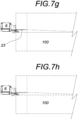
- the printed label (101) circulates through the feeding ramp (8) associated with the printer such that it is partially placed between the two laminar elements, such that once said printed label (101) is deposited, the blades (23) move down vertically and then move back horizontally to their retracted position.
- the printed label (101) is arranged such that a segment of the label is inserted and concealed between two laminar elements and a second segment of the label is oriented in a vertical plane that facilitates its visibility.
- the printed label (101) exits the printing means in printed form towards one side of the stack of sheets (100) in an inclined plane with respect to the horizontal plane, as a result of the arrangement of the feeding ramp (8).
- the printed label (101) can advantageously be placed on stacks of sheets of any height.
Landscapes
- Engineering & Computer Science (AREA)
- Mechanical Engineering (AREA)
- Physics & Mathematics (AREA)
- General Physics & Mathematics (AREA)
- Theoretical Computer Science (AREA)
- Sheets, Magazines, And Separation Thereof (AREA)
- Pile Receivers (AREA)
- Labeling Devices (AREA)
- Making Paper Articles (AREA)
Applications Claiming Priority (2)
| Application Number | Priority Date | Filing Date | Title |
|---|---|---|---|
| ES202130953A ES2926850B2 (es) | 2021-10-11 | 2021-10-11 | Máquina y procedimiento de etiquetado de una pila de elementos |
| PCT/ES2022/070642 WO2023062262A2 (es) | 2021-10-11 | 2022-10-11 | Máquina y procedimiento de etiquetado de una pila de elementos |
Publications (3)
| Publication Number | Publication Date |
|---|---|
| EP4417531A2 true EP4417531A2 (de) | 2024-08-21 |
| EP4417531B1 EP4417531B1 (de) | 2025-11-26 |
| EP4417531C0 EP4417531C0 (de) | 2025-11-26 |
Family
ID=83742484
Family Applications (1)
| Application Number | Title | Priority Date | Filing Date |
|---|---|---|---|
| EP22835857.8A Active EP4417531B1 (de) | 2021-10-11 | 2022-10-11 | Maschine und verfahren zum etiketieren eines stapels von elementen |
Country Status (4)
| Country | Link |
|---|---|
| US (1) | US12168542B2 (de) |
| EP (1) | EP4417531B1 (de) |
| ES (1) | ES2926850B2 (de) |
| WO (1) | WO2023062262A2 (de) |
Families Citing this family (1)
| Publication number | Priority date | Publication date | Assignee | Title |
|---|---|---|---|---|
| ES1311968Y (es) * | 2024-08-30 | 2025-02-26 | Al Gar Projects S L | Máquina etiquetadora con robot colaborativo |
Family Cites Families (5)
| Publication number | Priority date | Publication date | Assignee | Title |
|---|---|---|---|---|
| US4359218A (en) * | 1980-06-23 | 1982-11-16 | Beloit Corporation | Continuous sheet collection and discharge system |
| US4718158A (en) * | 1985-03-11 | 1988-01-12 | Charles Block | Automatic tagging apparatus and method therefor |
| JPH10211917A (ja) * | 1997-01-29 | 1998-08-11 | Oji Paper Co Ltd | 平板部材持ち上げ機構及びこれを用いた棚札インサー タ装置 |
| ITRE20010037A1 (it) * | 2001-04-06 | 2002-10-06 | Athos Claudio Mattioli | Applicatore automatico di etichette senza colla |
| CN108622709A (zh) * | 2017-03-22 | 2018-10-09 | 广东佛斯伯智能设备有限公司 | 片材堆垛器和形成片材堆垛的方法 |
-
2021
- 2021-10-11 ES ES202130953A patent/ES2926850B2/es active Active
-
2022
- 2022-10-11 US US18/700,463 patent/US12168542B2/en active Active
- 2022-10-11 EP EP22835857.8A patent/EP4417531B1/de active Active
- 2022-10-11 WO PCT/ES2022/070642 patent/WO2023062262A2/es not_active Ceased
Also Published As
| Publication number | Publication date |
|---|---|
| EP4417531B1 (de) | 2025-11-26 |
| US20240336389A1 (en) | 2024-10-10 |
| WO2023062262A3 (es) | 2023-06-01 |
| EP4417531C0 (de) | 2025-11-26 |
| WO2023062262A8 (es) | 2024-05-23 |
| US12168542B2 (en) | 2024-12-17 |
| WO2023062262A2 (es) | 2023-04-20 |
| ES2926850B2 (es) | 2023-07-21 |
| ES2926850A1 (es) | 2022-10-28 |
Similar Documents
| Publication | Publication Date | Title |
|---|---|---|
| EP2383108B1 (de) | Zähler/Ejektor einer Maschine zur Herstellung von Pappkartons | |
| JP2625401B2 (ja) | 板状加工物を打ち抜く機械の廃棄物剥取りステーション | |
| KR0130904B1 (ko) | 박판적층장치 | |
| US20130319194A1 (en) | Moving Workpiece Parts on Machine Tools | |
| EP4417531A2 (de) | Maschine und verfahren zum etikettieren eines elementenstapels | |
| US11279056B2 (en) | Device for carrying out cutting operations on open format edges of a printed product | |
| JPH072204A (ja) | 容器封止用蓋ストリップの位置決め方法および装置 | |
| JP2023503097A5 (de) | ||
| CN107840127A (zh) | 一种定子自动叠压机 | |
| EP3023240B1 (de) | Kartonherstellungsmaschine mit einer quadriervorrichtung in einem stückzahlauswerfer | |
| US20240300136A1 (en) | Sheet material processing tool, sheet material processing station, and sheet material processing machine | |
| US11331902B2 (en) | Blowing means unit and hot foil stamping and die-cutting device | |
| US11577928B2 (en) | Sheet processing machine comprising at least one pile formation device, and method for forming piles | |
| US12319532B2 (en) | Sheet processing machine | |
| KR20160047781A (ko) | 전자부품 라벨링 장비 | |
| US11891258B2 (en) | Sheet processing machine comprising at least one pile formation device, and method for forming piles | |
| EP0771749A1 (de) | Vorrichtung zur Kontrolle und Justierung der Stapelhöhe in Maschinen zum Herausgreifen von losen Bogenstapeln grosser Abmessungen | |
| JP2022145060A (ja) | 加工処理システム | |
| CN113879896B (zh) | 一种切割设备 | |
| US20250001636A1 (en) | Apparatus and method for carrying out cutting operations on format edges of at least one printed product configured with a jaw fold or cover | |
| US7540702B2 (en) | Device for stacking flat products | |
| CN212355934U (zh) | 胶印机中收纸防擦花装置 | |
| KR200263594Y1 (ko) | 골판지 자동 공급장치 | |
| KR100431632B1 (ko) | 골판지 자동 공급장치 | |
| EP0441360A2 (de) | Falzapparat für Druckpapier |
Legal Events
| Date | Code | Title | Description |
|---|---|---|---|
| STAA | Information on the status of an ep patent application or granted ep patent |
Free format text: STATUS: UNKNOWN |
|
| STAA | Information on the status of an ep patent application or granted ep patent |
Free format text: STATUS: THE INTERNATIONAL PUBLICATION HAS BEEN MADE |
|
| PUAI | Public reference made under article 153(3) epc to a published international application that has entered the european phase |
Free format text: ORIGINAL CODE: 0009012 |
|
| STAA | Information on the status of an ep patent application or granted ep patent |
Free format text: STATUS: REQUEST FOR EXAMINATION WAS MADE |
|
| 17P | Request for examination filed |
Effective date: 20240411 |
|
| AK | Designated contracting states |
Kind code of ref document: A2 Designated state(s): AL AT BE BG CH CY CZ DE DK EE ES FI FR GB GR HR HU IE IS IT LI LT LU LV MC ME MK MT NL NO PL PT RO RS SE SI SK SM TR |
|
| DAV | Request for validation of the european patent (deleted) | ||
| DAX | Request for extension of the european patent (deleted) | ||
| GRAP | Despatch of communication of intention to grant a patent |
Free format text: ORIGINAL CODE: EPIDOSNIGR1 |
|
| STAA | Information on the status of an ep patent application or granted ep patent |
Free format text: STATUS: GRANT OF PATENT IS INTENDED |
|
| INTG | Intention to grant announced |
Effective date: 20250508 |
|
| GRAS | Grant fee paid |
Free format text: ORIGINAL CODE: EPIDOSNIGR3 |
|
| GRAA | (expected) grant |
Free format text: ORIGINAL CODE: 0009210 |
|
| STAA | Information on the status of an ep patent application or granted ep patent |
Free format text: STATUS: THE PATENT HAS BEEN GRANTED |
|
| AK | Designated contracting states |
Kind code of ref document: B1 Designated state(s): AL AT BE BG CH CY CZ DE DK EE ES FI FR GB GR HR HU IE IS IT LI LT LU LV MC ME MK MT NL NO PL PT RO RS SE SI SK SM TR |
|
| REG | Reference to a national code |
Ref country code: CH Ref legal event code: F10 Free format text: ST27 STATUS EVENT CODE: U-0-0-F10-F00 (AS PROVIDED BY THE NATIONAL OFFICE) Effective date: 20251126 Ref country code: GB Ref legal event code: FG4D |
|
| REG | Reference to a national code |
Ref country code: DE Ref legal event code: R096 Ref document number: 602022025808 Country of ref document: DE |
|
| REG | Reference to a national code |
Ref country code: IE Ref legal event code: FG4D |
|
| U01 | Request for unitary effect filed |
Effective date: 20251217 |
|
| U07 | Unitary effect registered |
Designated state(s): AT BE BG DE DK EE FI FR IT LT LU LV MT NL PT RO SE SI Effective date: 20251223 |
|
| PG25 | Lapsed in a contracting state [announced via postgrant information from national office to epo] |
Ref country code: ES Free format text: LAPSE BECAUSE OF FAILURE TO SUBMIT A TRANSLATION OF THE DESCRIPTION OR TO PAY THE FEE WITHIN THE PRESCRIBED TIME-LIMIT Effective date: 20251126 |
|
| PG25 | Lapsed in a contracting state [announced via postgrant information from national office to epo] |
Ref country code: NO Free format text: LAPSE BECAUSE OF FAILURE TO SUBMIT A TRANSLATION OF THE DESCRIPTION OR TO PAY THE FEE WITHIN THE PRESCRIBED TIME-LIMIT Effective date: 20260226 |
|
| PG25 | Lapsed in a contracting state [announced via postgrant information from national office to epo] |
Ref country code: HR Free format text: LAPSE BECAUSE OF FAILURE TO SUBMIT A TRANSLATION OF THE DESCRIPTION OR TO PAY THE FEE WITHIN THE PRESCRIBED TIME-LIMIT Effective date: 20251126 |
|
| PG25 | Lapsed in a contracting state [announced via postgrant information from national office to epo] |
Ref country code: RS Free format text: LAPSE BECAUSE OF FAILURE TO SUBMIT A TRANSLATION OF THE DESCRIPTION OR TO PAY THE FEE WITHIN THE PRESCRIBED TIME-LIMIT Effective date: 20260226 |
|
| PG25 | Lapsed in a contracting state [announced via postgrant information from national office to epo] |
Ref country code: IS Free format text: LAPSE BECAUSE OF FAILURE TO SUBMIT A TRANSLATION OF THE DESCRIPTION OR TO PAY THE FEE WITHIN THE PRESCRIBED TIME-LIMIT Effective date: 20260326 |
|
| PG25 | Lapsed in a contracting state [announced via postgrant information from national office to epo] |
Ref country code: PL Free format text: LAPSE BECAUSE OF FAILURE TO SUBMIT A TRANSLATION OF THE DESCRIPTION OR TO PAY THE FEE WITHIN THE PRESCRIBED TIME-LIMIT Effective date: 20251126 |