EP4417119A2 - Elektrodenkonfigurationen zur diagnose von arrhythmien - Google Patents
Elektrodenkonfigurationen zur diagnose von arrhythmien Download PDFInfo
- Publication number
- EP4417119A2 EP4417119A2 EP24187456.9A EP24187456A EP4417119A2 EP 4417119 A2 EP4417119 A2 EP 4417119A2 EP 24187456 A EP24187456 A EP 24187456A EP 4417119 A2 EP4417119 A2 EP 4417119A2
- Authority
- EP
- European Patent Office
- Prior art keywords
- electrode
- approximately
- end effector
- surface area
- microelectrodes
- Prior art date
- Legal status (The legal status is an assumption and is not a legal conclusion. Google has not performed a legal analysis and makes no representation as to the accuracy of the status listed.)
- Pending
Links
Images





Classifications
-
- A—HUMAN NECESSITIES
- A61—MEDICAL OR VETERINARY SCIENCE; HYGIENE
- A61B—DIAGNOSIS; SURGERY; IDENTIFICATION
- A61B5/00—Measuring for diagnostic purposes; Identification of persons
- A61B5/24—Detecting, measuring or recording bioelectric or biomagnetic signals of the body or parts thereof
- A61B5/316—Modalities, i.e. specific diagnostic methods
- A61B5/318—Heart-related electrical modalities, e.g. electrocardiography [ECG]
- A61B5/367—Electrophysiological study [EPS], e.g. electrical activation mapping or electro-anatomical mapping
-
- A—HUMAN NECESSITIES
- A61—MEDICAL OR VETERINARY SCIENCE; HYGIENE
- A61B—DIAGNOSIS; SURGERY; IDENTIFICATION
- A61B18/00—Surgical instruments, devices or methods for transferring non-mechanical forms of energy to or from the body
- A61B18/04—Surgical instruments, devices or methods for transferring non-mechanical forms of energy to or from the body by heating
- A61B18/12—Surgical instruments, devices or methods for transferring non-mechanical forms of energy to or from the body by heating by passing a current through the tissue to be heated, e.g. high-frequency current
- A61B18/14—Probes or electrodes therefor
- A61B18/1492—Probes or electrodes therefor having a flexible, catheter-like structure, e.g. for heart ablation
-
- A—HUMAN NECESSITIES
- A61—MEDICAL OR VETERINARY SCIENCE; HYGIENE
- A61B—DIAGNOSIS; SURGERY; IDENTIFICATION
- A61B5/00—Measuring for diagnostic purposes; Identification of persons
- A61B5/24—Detecting, measuring or recording bioelectric or biomagnetic signals of the body or parts thereof
- A61B5/25—Bioelectric electrodes therefor
- A61B5/262—Needle electrodes
-
- A—HUMAN NECESSITIES
- A61—MEDICAL OR VETERINARY SCIENCE; HYGIENE
- A61B—DIAGNOSIS; SURGERY; IDENTIFICATION
- A61B5/00—Measuring for diagnostic purposes; Identification of persons
- A61B5/24—Detecting, measuring or recording bioelectric or biomagnetic signals of the body or parts thereof
- A61B5/25—Bioelectric electrodes therefor
- A61B5/279—Bioelectric electrodes therefor specially adapted for particular uses
- A61B5/28—Bioelectric electrodes therefor specially adapted for particular uses for electrocardiography [ECG]
- A61B5/283—Invasive
- A61B5/287—Holders for multiple electrodes, e.g. electrode catheters for electrophysiological study [EPS]
-
- A—HUMAN NECESSITIES
- A61—MEDICAL OR VETERINARY SCIENCE; HYGIENE
- A61B—DIAGNOSIS; SURGERY; IDENTIFICATION
- A61B5/00—Measuring for diagnostic purposes; Identification of persons
- A61B5/68—Arrangements of detecting, measuring or recording means, e.g. sensors, in relation to patient
- A61B5/6846—Arrangements of detecting, measuring or recording means, e.g. sensors, in relation to patient specially adapted to be brought in contact with an internal body part, i.e. invasive
- A61B5/6847—Arrangements of detecting, measuring or recording means, e.g. sensors, in relation to patient specially adapted to be brought in contact with an internal body part, i.e. invasive mounted on an invasive device
- A61B5/6852—Catheters
- A61B5/6853—Catheters with a balloon
-
- A—HUMAN NECESSITIES
- A61—MEDICAL OR VETERINARY SCIENCE; HYGIENE
- A61B—DIAGNOSIS; SURGERY; IDENTIFICATION
- A61B5/00—Measuring for diagnostic purposes; Identification of persons
- A61B5/68—Arrangements of detecting, measuring or recording means, e.g. sensors, in relation to patient
- A61B5/6846—Arrangements of detecting, measuring or recording means, e.g. sensors, in relation to patient specially adapted to be brought in contact with an internal body part, i.e. invasive
- A61B5/6847—Arrangements of detecting, measuring or recording means, e.g. sensors, in relation to patient specially adapted to be brought in contact with an internal body part, i.e. invasive mounted on an invasive device
- A61B5/6852—Catheters
- A61B5/6858—Catheters with a distal basket, e.g. expandable basket
-
- A—HUMAN NECESSITIES
- A61—MEDICAL OR VETERINARY SCIENCE; HYGIENE
- A61B—DIAGNOSIS; SURGERY; IDENTIFICATION
- A61B17/00—Surgical instruments, devices or methods
- A61B2017/00017—Electrical control of surgical instruments
- A61B2017/00022—Sensing or detecting at the treatment site
- A61B2017/00039—Electric or electromagnetic phenomena other than conductivity, e.g. capacity, inductivity, Hall effect
- A61B2017/00044—Sensing electrocardiography, i.e. ECG
- A61B2017/00048—Spectral analysis
- A61B2017/00053—Mapping
-
- A—HUMAN NECESSITIES
- A61—MEDICAL OR VETERINARY SCIENCE; HYGIENE
- A61B—DIAGNOSIS; SURGERY; IDENTIFICATION
- A61B18/00—Surgical instruments, devices or methods for transferring non-mechanical forms of energy to or from the body
- A61B2018/00053—Mechanical features of the instrument of device
- A61B2018/00107—Coatings on the energy applicator
- A61B2018/00136—Coatings on the energy applicator with polymer
-
- A—HUMAN NECESSITIES
- A61—MEDICAL OR VETERINARY SCIENCE; HYGIENE
- A61B—DIAGNOSIS; SURGERY; IDENTIFICATION
- A61B18/00—Surgical instruments, devices or methods for transferring non-mechanical forms of energy to or from the body
- A61B2018/00053—Mechanical features of the instrument of device
- A61B2018/00107—Coatings on the energy applicator
- A61B2018/00148—Coatings on the energy applicator with metal
-
- A—HUMAN NECESSITIES
- A61—MEDICAL OR VETERINARY SCIENCE; HYGIENE
- A61B—DIAGNOSIS; SURGERY; IDENTIFICATION
- A61B18/00—Surgical instruments, devices or methods for transferring non-mechanical forms of energy to or from the body
- A61B2018/00053—Mechanical features of the instrument of device
- A61B2018/0016—Energy applicators arranged in a two- or three dimensional array
-
- A—HUMAN NECESSITIES
- A61—MEDICAL OR VETERINARY SCIENCE; HYGIENE
- A61B—DIAGNOSIS; SURGERY; IDENTIFICATION
- A61B18/00—Surgical instruments, devices or methods for transferring non-mechanical forms of energy to or from the body
- A61B2018/00053—Mechanical features of the instrument of device
- A61B2018/00214—Expandable means emitting energy, e.g. by elements carried thereon
- A61B2018/00267—Expandable means emitting energy, e.g. by elements carried thereon having a basket shaped structure
-
- A—HUMAN NECESSITIES
- A61—MEDICAL OR VETERINARY SCIENCE; HYGIENE
- A61B—DIAGNOSIS; SURGERY; IDENTIFICATION
- A61B18/00—Surgical instruments, devices or methods for transferring non-mechanical forms of energy to or from the body
- A61B2018/00315—Surgical instruments, devices or methods for transferring non-mechanical forms of energy to or from the body for treatment of particular body parts
- A61B2018/00345—Vascular system
- A61B2018/00351—Heart
-
- A—HUMAN NECESSITIES
- A61—MEDICAL OR VETERINARY SCIENCE; HYGIENE
- A61B—DIAGNOSIS; SURGERY; IDENTIFICATION
- A61B18/00—Surgical instruments, devices or methods for transferring non-mechanical forms of energy to or from the body
- A61B2018/00571—Surgical instruments, devices or methods for transferring non-mechanical forms of energy to or from the body for achieving a particular surgical effect
- A61B2018/00577—Ablation
-
- A—HUMAN NECESSITIES
- A61—MEDICAL OR VETERINARY SCIENCE; HYGIENE
- A61B—DIAGNOSIS; SURGERY; IDENTIFICATION
- A61B18/00—Surgical instruments, devices or methods for transferring non-mechanical forms of energy to or from the body
- A61B2018/00636—Sensing and controlling the application of energy
- A61B2018/00773—Sensed parameters
- A61B2018/00839—Bioelectrical parameters, e.g. ECG, EEG
-
- A—HUMAN NECESSITIES
- A61—MEDICAL OR VETERINARY SCIENCE; HYGIENE
- A61B—DIAGNOSIS; SURGERY; IDENTIFICATION
- A61B2562/00—Details of sensors; Constructional details of sensor housings or probes; Accessories for sensors
- A61B2562/02—Details of sensors specially adapted for in-vivo measurements
- A61B2562/0209—Special features of electrodes classified in A61B5/24, A61B5/25, A61B5/283, A61B5/291, A61B5/296, A61B5/053
-
- A—HUMAN NECESSITIES
- A61—MEDICAL OR VETERINARY SCIENCE; HYGIENE
- A61B—DIAGNOSIS; SURGERY; IDENTIFICATION
- A61B2562/00—Details of sensors; Constructional details of sensor housings or probes; Accessories for sensors
- A61B2562/04—Arrangements of multiple sensors of the same type
-
- A—HUMAN NECESSITIES
- A61—MEDICAL OR VETERINARY SCIENCE; HYGIENE
- A61B—DIAGNOSIS; SURGERY; IDENTIFICATION
- A61B5/00—Measuring for diagnostic purposes; Identification of persons
- A61B5/68—Arrangements of detecting, measuring or recording means, e.g. sensors, in relation to patient
- A61B5/6846—Arrangements of detecting, measuring or recording means, e.g. sensors, in relation to patient specially adapted to be brought in contact with an internal body part, i.e. invasive
- A61B5/6847—Arrangements of detecting, measuring or recording means, e.g. sensors, in relation to patient specially adapted to be brought in contact with an internal body part, i.e. invasive mounted on an invasive device
- A61B5/6852—Catheters
- A61B5/6859—Catheters with multiple distal splines
Definitions
- Cardiac arrhythmias such as atrial fibrillation, occur when regions of cardiac tissue abnormally conduct electric signals. Procedures for treating arrhythmia include surgically disrupting the conducting pathway for such signals.
- energy e.g., radiofrequency (RF) energy
- RF radiofrequency
- EP mapping may include the use of sensing electrodes on a catheter (e.g., the same catheter that is used to perform the ablation). Such sensing electrodes may monitor electrical signals within the cardiovascular system to pinpoint the location of aberrant conductive tissue sites that are responsible for the arrhythmia. Examples of an EP mapping system are described in U.S. Pat. No. 5,738,096, entitled “Cardiac Electromechanics,” issued April 14, 1998 , the disclosure of which is incorporated by reference herein in its entirety. Examples of EP mapping catheters are described in U.S. Pat. No.
- some catheter ablation procedures may be performed using an image guided surgery (IGS) system.
- IGS image guided surgery
- the IGS system may enable the physician to visually track the location of the catheter within the patient, in relation to images of anatomical structures within the patient, in real time.
- Some systems may provide a combination of EP mapping and IGS functionalities, including the CARTO 3 ® system by Biosense Webster, Inc. of Irvine, California. Examples of catheters that are configured for use with an IGS system are disclosed in U.S. Pat. No. 9,480,416, entitled "Signal Transmission Using Catheter Braid Wires," issued November 1, 2016 , the disclosure of which is incorporated by reference herein in its entirety; and various other references that are cited herein.
- the terms “about” or “approximately” for any numerical values or ranges indicate a suitable dimensional tolerance that allows the part or collection of components to function for its intended purpose as described herein. More specifically, “about” or “approximately” may refer to the range of values ⁇ 10% of the recited value, e.g. “about 90%” may refer to the range of values from 81% to 99%.
- the terms “patient,” “host,” “user,” and “subject” refer to any human or animal subject and are not intended to limit the systems or methods to human use, although use of the subject invention in a human patient represents a preferred embodiment.
- FIG. 1 shows an exemplary mapping catheter assembly (2) that may be used to provide EP mapping within the heart or other cardiovascular anatomical structures within a patient.
- Catheter assembly (2) of this example includes a control handle (16) and a catheter (10) extending distally from control handle (16).
- Catheter (10) includes a proximal portion (12) and a distal deflection portion (14), which is laterally deflectable relative to proximal portion (12) in response to actuation of a deflection control knob (11) of control handle (16) as will be described in greater detail below.
- An end effector (15) is positioned at the distal end of catheter (10).
- end effector includes a plurality of spines (42) having respective free ends, each spine carrying at least one pair of closely-spaced bipolar microelectrodes (85), which are configured to pick up electrocardiogram signals from tissue.
- proximal portion (12) of catheter (10) is flexible but substantially non-compressible along its length.
- proximal portion (12) of catheter (10) includes an outer wall (17) positioned coaxially about a stiffening tube (20).
- the outer diameter of proximal portion (12) may be less than approximately 8 French.
- Stiffening tube (20) and outer wall (17) are together configured to provide substantial torsional stability while also providing a minimal wall thickness. Due to the torsional stability provided by stiffening tube (20) and outer wall (17), when control handle (16) is rotated, deflection portion (14) of catheter (10) and end effector (15) will rotate in a corresponding manner.
- stiffening tube (20) is omitted.
- a lumen (18) extends through the interior of stiffening tube (20).
- Lumen (18) is sized to accommodate various components, including, for example, one or more puller wires, electrode lead wires, irrigation tubing, and any other wires and/or cables as described below.
- deflection portion (14) of catheter (10) includes a tube body (19) that defines a central lumen (23) and a plurality of off-axis lumens (21, 22, 24, 25) that are sized to accommodate various components as described below.
- tube body (19) is formed of a material that is more flexible than proximal portion (12) of catheter (10).
- a set of lead wires (30) are contained in a nonconductive sheath (60) and extend through the length of catheter (10). As shown in FIGS. 2-3 , lead wires (30) and sheath (60) are positioned in lumens (18, 21). Lead wires (30) are coupled with microelectrodes (85) as will be described in greater detail below.
- a set of puller wires (32A, 32B) are contained in respective sheaths (39) and extend through the length of catheter (10). Puller wires (32A, 32B) are positioned in lumen (18) and respective lumens (22, 24); and are angularly offset from each other by 180 degrees in the present example. Puller wires (32A, 32B) are operable to provide bi-directional lateral deflection of deflection portion (14) as will be described in greater detail below.
- a guidewire tube (38) also extends through the length of catheter (10) and is positioned in lumens (18, 23).
- Guidewire tube (38) is configured to slidably accommodate a conventional guidewire (not shown), which may be used to assist in guiding catheter (10) in various ways as will be apparent to those skilled in the art in view of the teachings herein.
- a sensor cable (34) also extends through the length of catheter (10) and is positioned in lumens (18, 25). Sensor cable (34) is coupled with an electromagnetic position sensor (36) as will be described in greater detail below.
- a mounting stem (46) extends between deflection portion (14) and end effector (15).
- Stem (46) is in the form of a short tubing mounted on a distal end of tube body (19).
- Stem (46) has a central lumen (48) to house various components, including position sensor (36) and a distal anchor for puller wires (32A, 32B).
- the distal anchor includes a pair of washers (50D, 50P), each of which has a plurality of through-holes (52, 54) that allow passage of components between deflection portion (14) and stem (46).
- Through-holes (52, 54) are axially aligned with lumens (22, 24) of tube body (19), respectively, to receive a distal end of puller wires (32A, 32B), respectively.
- washers (50D, 50P) With tension on washers (50D, 50P), exerted by puller wires (32A, 32B), washers (50D, 50P) firmly and fixedly abut against the distal end of tube body (19) of the deflection portion (14).
- Each washer (50D, 50P) includes through-hole (51) that is axially aligned with lumen (21) and allows passage of lead wires (30) from deflection portion (14) and into lumen (48).
- Each washer (50D, 50P) also includes through-hole (55) that is axially aligned with lumen (25) and allows passage of sensor cable (34) into lumen (48) where the position sensor (36) is housed.
- Each washer (50D, 50P) further includes on-axis through-hole (53), which is axially aligned with lumen (23) and allows passage of guidewire tubing (38) into lumen (48).
- puller wires (32A, 32B) are provided for bi-directional deflection of deflection portion (14).
- the puller wires (32A, 32B) are actuated by mechanisms in control handle (16) that are responsive to a thumb control knob or a deflection control knob (11) (see FIG. 1 ).
- deflection controls may be provided in accordance with the teachings of any one or more of U.S. Pat. Nos. 6,123,699 ; 6,171,277 ; 6,183,435 ; 6,183,463 ; 6,198,974 ; 6,210,407 and 6,267,746 .
- end effector (15) of mapping catheter assembly (2) includes a set of ring electrodes (27) positioned at the distal end of catheter (10) and a plurality of spines (42), each spine carrying at least one pair of closely-spaced bipolar microelectrodes (85).
- the microelectrodes (85) of a pair has a separation space gap distance therebetween of no greater than about 200 microns.
- At least one pair of closely-spaced bipolar microelectrodes (85) are provided on each spine (42) in the present example. More particularly, in the present example, each spine (42) carries four pairs of bipolar microelectrodes (85) for a total of eight microelectrodes (85) per spine (42).
- end effector (15) may include two to eight spines (42); or more spines (42) as desired. While the spines (42) are shown having respective free ends, other versions may have at least one free end of one spine connect to another free end of another spine with a continuous member.
- each spine (42) has a support member (43) and a non-conductive covering (44) that extends along each spine (42).
- a proximal portion of each spine (42) extends proximally into lumen (48) of stem (46).
- Spines (42) arranged uniformly about the distal opening of stem (46) in equiangular distances from each other.
- An adhesive (not shown) seals the distal end of stem (46) around the proximal portions of spines (42); while leaving open the distal end of guidewire tube (38).
- each spine support member (43) is made of a material having shape-memory (e.g., nitinol, etc.).
- Non-conductive covering (44) can be made of any suitable material, such as a biocompatible plastic (e.g., polyurethane or PEBAX).
- Lead wires (30) for microelectrodes (85) carried on the spines (42) extend through both portions (12, 14) of catheter (10) protected by nonconductive sheath (60).
- lead wires (30) extend through a polytube (68), as shown in FIG. 4 .
- Lead wires (30) diverge at the distal end of polytube (68) and extend toward their respective spine (42). While only one spine (42) is shown in FIG. 4 , polytube (68) may be sized appropriately to receive the proximal ends of all spines (42).
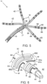
- each spine (42) includes a flexible microelectrode member in the form of a panel (80) that is affixed to the outer surface of spine (42), conforming to the shape of spine (42).
- panel (80) includes a biocompatible flexible plastic substrate (81) with at least one pair of close-spaced microelectrodes (85), separated therebetween by a non-conducting gap space (Lg).
- substrate (81) is generally elongated with a thinner (T) portion (82), at least one distal wider portion (83) traversing longitudinal portion (82) at a generally perpendicular angle, and a proximal base portion (84a or 84c) having a slightly greater lateral dimension than longitudinal portion (82).
- Longitudinal portion (82) is configured to extend along the length of spine (42) and lateral portion (83a, 83b, 83c) is configured to wrap circumferentially around a distal portion of spine (42) (R in FIG. 5 ).
- Base portion (84a, 84c) is positioned on a proximal end portion of spine (42) and is thus protected within lumen (48).
- soldering patches (88) are soldering patches (88), one for each lead wire (30) whose distal end is soldered to a respective soldering patch (88). Soldering patches (88) are therefore protected and insulated within lumen (48).
- microelectrodes (85) are affixed or otherwise provided in alignment with lateral portion (83), on an outer surface of each lateral portion (83), such that each microelectrode (85) generally forms a ring microelectrode (R) when lateral portion (83) is wrapped circumferentially around spine (42).
- Longitudinal portion (82) may be as wide as lateral portion (83), though the amount of surface area coverage or thickness of the substrate may affect the flexibility of spine (42).
- Microelectrodes (85) may be made of any suitable solid conductive material, such as platinum or gold, or a combination of platinum and iridium. Some versions of microelectrodes (85) are coated with iridium oxide or are plasma treated to improve the signals to noise characteristics of the microelectrodes.
- the space gap distance (Lg) separating each microelectrode (85) of a pair ranges from about 50 to about 300 microns. In some versions, the space gap distance (Lg) separating each microelectrode (85) of a pair ranges from about 100 to about 200 microns. In some versions, the space gap distance (Lg) separating each microelectrode (85) of a pair is about 50 microns. Moreover, in some versions, each microelectrode (85) itself may have a width (W) ranging from about 50 microns to about 100 microns.
- panel (80) has a length of about 8.0 cm, wherein longitudinal portion (82) has a length of about 5.0 cm and a width no greater than about 1.0 mm; and base portion (84) has a length of about 3.0 cm and a width of about 1.2 mm.
- Each pair of microelectrodes (85) is spaced apart from an adjacent pair of microelectrodes (85) by a distance of about 5.0 mm, with each microelectrode (85) having a width of about 50 microns and a length of about 2.56 mm.
- Other suitable dimensions and arrangements will be described in greater detail below.
- substrate (81) of the present example is formed of a first or outer layer (81a), a second or middle layer (81b), and a third or inner layer (81c), each having a first surface (91) defined by surfaces (91c, 91b, 91c), and a second surface (92) defined by surfaces (92a, 92b, 92c) that extend along a longitudinal axis L-L.
- first surface (91) defined by surfaces (91c, 91b, 91c)
- second surface (92) defined by surfaces (92a, 92b, 92c) that extend along a longitudinal axis L-L.
- Microelectrodes (85) are applied to or otherwise deposited on first surface (91a) of outer layer (81a) to overlie through-holes (86a), which are formed in layer (81a) to provide connection access for electrical traces (87b) that extend along first surface (91b) of longitudinal portion (82b) of second layer (81b) between corresponding microelectrodes (85) and soldering pads (88) carried on second surface (92c) of base portion (84c) of the third layer (81c). Additional traces (87c) run along first surface (91c) of third layer (81c).
- Through-holes (86b, 89b, 89c) are formed in layers (81b, 81c) to provide connection access for electrical traces (87b, 87c) to more proximal microelectrodes (85) and more proximal soldering pads (not shown in FIG. 7 ).
- substrate (81) has three layers with each layer (81a, 81b, 81c) carrying four traces (87). It is understood that there is one corresponding trace (87) and one corresponding soldering pad (88) for each microelectrode (85) in this example. Each lead wire (30) is soldered to a corresponding soldering pad (88). In that regard, it is also understood that traces (87) may be arranged differently, in different patterns, and/or on different layers (81), as needed or appropriate. Adjacent microelectrodes (85) are separated by a space (Lg) and each microelectrode (85) may have a width (W) having the dimensions noted earlier and defined later in FIG. 13A .
- substrate (81) is affixed to nonconductive covering (44) of the spine (42) with the longitudinal portion (82) extending longitudinally along spine (42) and lateral portions (83) wrapped circumferentially around spine (42).
- the lateral dimension or width (W) as referenced to longitudinal axis L-L of lateral portions (83), and more significantly of microelectrodes (85) is comparable to the circumference of spine (42) such that opposing ends (85E) of microelectrodes (85) can reach each other or at least come in close contact to generally form and function as ring microelectrodes (R) carried on spine (42).
- substrate (81) is affixed to the forward-facing or distal side of the spine (42) that is adapted to contact tissue.
- each spine (42) is pre-formed with a slight inward curvature such that end effector (15) has a generally slightly concave configuration resembling an open umbrella.
- This preformed configuration enables each spine (42) to engage a tissue surface (93) generally along its entire length when end effector (15) is advanced distally against the tissue surface (93), as shown in FIG. 8 .
- FIGS. 9-10 show components of another exemplary multi-ray end effector (117) that may be incorporated into mapping catheter assembly (2) in place of end effector (15) in which each spine (142) defines a longitudinal axis L-L.
- end effector (117) may be incorporated into various other kinds of mapping catheter assemblies.
- End effector (117) of this example includes a plurality of spines (142) with pairs of microelectrodes (185) mounted thereon. Whereas spine (42) of FIG. 6 has a more circular cross-section, spine (142) of FIG. 9 has a more rectangular cross section, which provides the greater planar surface (100) on which a flexible microelectrode member in the form of a panel (180) can be selectively applied or affixed.
- microelectrodes (185) (including their ends (180E)) is confined to the surface area of planar surface (100).
- Spines (142) thus have microelectrodes (185) on only one side of each spine (142) (i.e., the tissue-contacting side of each spine (142)). Therefore, generally the entirety of microelectrodes (185) is in contact with tissue (193) when planar surface (100) is in contact with tissue (193), as shown in FIG. 10 .
- Having spines (142) with a rectangular cross-section wherein the X dimension along the planar surface (100) and transverse to the L-L axis is greater than the Y dimension perpendicularly to the X dimension, as shown in FIG. 9 may help minimize kinking and stress to spines (142) at their area of greatest flexion or divergence (D) (see FIG. 10 ).
- Support member (143) has a rectangular cross-section which is adopted by heat-shrink nonconductive covering (144) to provide the greater planar surface (100).
- Substrate (181) of panel (180) comprises multiple layers (181a, 181b, 181c) in the present example. However, substrate (181) is devoid of lateral portions, with a longitudinal portion having a lateral dimension (W) that is comparable or at least no greater than the lateral dimension of planar surface (100) so that substrate (181) remains confined on planar surface (100).
- Microelectrodes (185) are elongated and thin, with a rectangular shape in this example. Microelectrodes (185) may be made of any suitable solid conductive material, such as platinum or gold, or a combination of platinum and iridium. Some versions of microelectrodes (185) are coated with iridium oxide or are plasma treated.
- end effector (15) includes a position sensor (36).
- Position sensor (36) is operable to generate signals that are indicative of the position and orientation of end effector (15) within the patient.
- position sensor (36) includes a wire coil or a plurality of wire coils (e.g., three orthogonal coils) that are configured to generate electrical signals in response to the presence of an alternating electromagnetic field generated by field generators that are positioned near the patient.
- Such position sensing capabilities may be provided in accordance with the teachings of any of the various patent references cited herein.
- End effector (117) may also include a position sensor (36) or variations thereof.
- end effector 15, 117
- Other components and techniques that may be used to generate real-time position data associated with end effector may include wireless triangulation, acoustic tracking, optical tracking, inertial tracking, and the like.
- position sensing capabilities may be omitted from end effector (15, 117).
- catheter (10) may be inserted into a patient's cardiovascular system (e.g., via a femoral artery, etc.), with deflection control knob (11) and deflection portion (14) being used to steer end effector (15, 117) to a desired location (e.g., in or near a pulmonary vein, etc.).
- an outer sheath (not shown) may be positioned about end effector (15, 117) to constrain spines (42) as end effector (15, 117) is advanced to the target location.
- the outer sheath may be retracted after end effector (15, 117) reaches or nears the target location.
- This positioning may be performed with assistance from an image guided surgical system that is in communication with position sensor (36) using known techniques.
- microelectrodes 85, 185 may be placed in contact with the cardiovascular tissue to obtain electrocardiogram signals.
- the multi-ray configuration of end effector (15, 117) may enable several electrocardiogram signals to be picked up simultaneously from various regions of anatomy within the cardiovascular space.
- These electrocardiogram signals may be used to provide EP mapping, to thereby pinpoint the location(s) of aberrant conductive tissue sites that are responsible for cardiac arrhythmia. Once these aberrant conductive tissue sites are identified, the EP map data can be used to guide an ablation catheter to ablate the tissue to thereby treat the arrhythmia.
- FIG. 11 shows another exemplary end effector (200) that may be incorporated into mapping catheter assembly (2) in place of end effector (15).
- end effector (200) may be incorporated into various other kinds of mapping catheter assemblies.
- End effector (200) of this example includes an expandable assembly (220) that is formed by an angularly spaced array of beams (222).
- Each beam (222) includes four pairs (230) of bipolar microelectrodes (232, 234).
- Microelectrodes (232, 234) are each generally rectangular and are configured to pick up electrocardiogram signals from tissue, just like microelectrodes (85, 185) described above.
- Microelectrodes (232, 234) may be made of any suitable solid conductive material, such as platinum or gold, or a combination of platinum and iridium. Some versions of microelectrodes (232, 234) are coated with iridium oxide or are plasma treated. The entirety of each microelectrode (232, 234) is confined to the outwardly presented surface of each beam (222) in the present example. Beams (222) thus have microelectrodes (232, 234) on only one side of each beam (222) (i.e., the tissue-contacting side of each beam (222)). Except as otherwise described herein, the various features of end effector (200) may be configured and operable like end effectors (15, 117) described above.
- the proximal ends of beams (222) are positioned in an outer shaft (210), which may be considered as being analogous to mounting stem (46) described above.
- the distal ends of beams (222) are coupled with a hub member (212).
- hub member (212) is secured to a central inner shaft (216), which is coaxially positioned at the center of expandable assembly (220).
- Beams (222) are configured to transition expandable assembly (220) between a non-expanded state and an expanded state. The expanded state is shown in FIG. 11 . When expandable assembly (220) is in the non-expanded state, beams (222) are urged inwardly to define an effective outer diameter that is less than or equal to the inner diameter of outer shaft (210).
- beams (222) are resiliently biased to provide expandable assembly (220) in the expanded state.
- an outer sheath (214) is slidably disposed about outer shaft (210). When sheath (214) is in a distal position (e.g., such that the distal end of sheath (214) is distal to hub member (212)), sheath (214) constrains beams (222) inwardly, thereby maintaining expandable assembly (220) in the non-expanded state. When sheath (214) is in a proximal position (e.g., as shown in FIG.
- beams (222) may resiliently provide expandable assembly (220) in the expanded state.
- inner shaft (216) may be omitted.
- the state of expandable assembly (220) may be based on the relative longitudinal positioning of inner shaft (216) and outer shaft (210).
- an actuator on control handle (16) may drive outer shaft (210) proximally relative to inner shaft (216) to urge expandable assembly (220) to the non-expanded state; and drive outer shaft (210) distally relative to inner shaft (216) to urge expandable assembly (220) to the expanded state.
- an actuator on control handle (16) may drive inner shaft (216) distally relative to outer shaft (210) to urge expandable assembly (220) to the non-expanded state; and drive inner shaft (216) proximally relative to inner shaft (210) to urge expandable assembly (220) to the expanded state.
- Various suitable forms of inputs that may be provided on control handle (16) to provide such actuation, as well as various suitable ways in which expandable assembly (220) may transition between the non-expanded state and the expanded state, will be apparent to those skilled in the art in view of the teachings herein.
- catheter (10) may be inserted into a patient's cardiovascular system (e.g., via a femoral artery, etc.), with deflection control knob (11) and deflection portion (14) being used to steer end effector (200) to a desired location (e.g., in or near a pulmonary vein, etc.).
- a desired location e.g., in or near a pulmonary vein, etc.
- expandable assembly (220) may be maintained in the non-expanded state in accordance with the teachings herein.
- expandable assembly (220) may be transitioned to the expanded state in accordance with the teachings herein.
- end effector (200) includes a position sensor like position sensor (36)
- the positioning of end effector (200) may be performed with assistance from an image guided surgical system that is in communication with the position sensor.
- microelectrodes (232, 234) may be placed in contact with the cardiovascular tissue to obtain electrocardiogram signals.
- the basket-shaped configuration of end effector (200) may enable various electrode pairs (230) to contact various regions of tissue simultaneously, thereby enabling end effector (200) to pick up several electrocardiogram signals simultaneously from various regions of anatomy within the cardiovascular space.
- These electrocardiogram signals may be used to provide EP mapping, to thereby pinpoint the location(s) of aberrant conductive tissue sites that are responsible for cardiac arrhythmia. Once these aberrant conductive tissue sites are identified, the EP map data can be used to guide an ablation catheter to ablate the tissue to thereby treat the arrhythmia.
- FIG. 12 shows another exemplary end effector (300) that may be incorporated into mapping catheter assembly (2) in place of end effector (15).
- end effector (300) may be incorporated into various other kinds of mapping catheter assemblies.
- End effector (300) of this example includes an expandable assembly (320) that is formed by an expandable balloon (324) with a plurality of flex circuits (322) secured thereto. Flex circuits (322) are positioned in an angularly spaced array about balloon (324). Each flex circuit (322) includes a flexible substrate (326) with four pairs (330) of bipolar microelectrodes (332, 334).
- Microelectrodes (332, 334) are each generally rectangular and are configured to pick up electrocardiogram signals from tissue, just like microelectrodes (85, 185) described above.
- Microelectrodes (332, 334) may be made of any suitable solid conductive material, such as platinum or gold, or a combination of platinum and iridium. Some versions of microelectrodes (332, 334) are coated with iridium oxide or are plasma treated. The entirety of each microelectrode (332, 334) is confined to the outwardly presented surface of each flexible substrate (326) in the present example.
- Flexible substrates (326) thus have microelectrodes (332, 334) on only one side of each flexible substrate (326) (i.e., the tissue-contacting side of each flexible substrate (326)). Except as otherwise described herein, the various features of end effector (300) may be configured and operable like end effectors (15, 117) described above.
- flex circuits (322) terminate distal to the proximal end of balloon (324).
- the distal ends of flex circuits (322) are joined at a hub (312), which is positioned at a distal end of balloon (324).
- Balloon (324) is positioned at the distal end of an outer shaft (310), which may be considered as being analogous to mounting stem (46) described above.
- Balloon (324) is in fluid communication with a source of inflation fluid (e.g., saline, etc.), such that the inflation fluid may be driven into balloon (324) to transition balloon (324) to the inflated state, thereby providing expandable assembly (320) in the expanded state (as shown in FIG. 12 ).
- a source of inflation fluid e.g., saline, etc.
- the inflation fluid may be drawn from balloon (324) to transition balloon (324) from the inflated state to the non-inflated state, thereby transitioning expandable assembly (320) to the non-expanded state.
- a central shaft (not shown) is positioned in balloon (324) to maintain consistent spacing between hub (312) and the distal end of outer shaft (310), regardless of expandable assembly (320) is in the expanded or non-expanded state.
- balloon (324) may be inflated and deflated will be apparent to those skilled in the art in view of the teachings herein.
- catheter (10) may be inserted into a patient's cardiovascular system (e.g., via a femoral artery, etc.), with deflection control knob (11) and deflection portion (14) being used to steer end effector (300) to a desired location (e.g., in or near a pulmonary vein, etc.).
- end effector (300) As end effector (300) is advanced to the target location, expandable assembly (300) may be maintained in the non-expanded state in accordance with the teachings herein. After end effector (300) reaches or nears the target location, expandable assembly (320) may be transitioned to the expanded state in accordance with the teachings herein.
- end effector (300) includes a position sensor like position sensor (36)
- the positioning of end effector (300) may be performed with assistance from an image guided surgical system that is in communication with the position sensor.
- microelectrodes (332, 334) may be placed in contact with the cardiovascular tissue to obtain electrocardiogram signals.
- the bulbous configuration of end effector (300) may enable various electrode pairs (330) to contact various regions of tissue simultaneously, thereby enabling end effector (300) to pick up several electrocardiogram signals simultaneously from various regions of anatomy within the cardiovascular space.
- These electrocardiogram signals may be used to provide EP mapping, to thereby pinpoint the location(s) of aberrant conductive tissue sites that are responsible for cardiac arrhythmia. Once these aberrant conductive tissue sites are identified, the EP map data can be used to guide an ablation catheter to ablate the tissue to thereby treat the arrhythmia.
- the electrocardiogram signals picked up by the electrodes may include a large amount if not a majority of far field signals generated from cardiovascular structures that are not the particular structure being targeted by the microelectrodes.
- a physician may place microelectrodes in contact with tissue in the heart (such as, for example, the pulmonary vein) to detect electrocardiogram signals at the site in the heart.
- the atria of the patient's heart may be generating electrocardiogram signals having a greater amplitude than those of the site (e.g., at pulmonary vein), and those electrocardiogram signals may be picked up by the microelectrodes at the pulmonary vein as far field signals.
- Other regions of cardiac tissue may also communicate far field signals that are picked up by microelectrodes at the pulmonary vein (or microelectrodes that are placed elsewhere within the cardiovascular space, at some distance from the cardiac tissue generating the far field signals). These far field signals are added to the near-field component and may ultimately yield an electrocardiogram signal that is artificially complex and fractionated, and therefore difficult to interpret.
- FIG. 14 shows a graph (500) of three electrocardiogram signal plots from a subject in atrial fibrillation (502, 504, 506) that are fractionated due to the fibrillatory nature of the signal as well as far field signals.
- plots (502, 504, 506) show voltages over time, as sensed by microelectrodes contacting tissue.
- plots (502, 504, 506) may represent electrocardiogram signals picked up by three different microelectrode pairs that are positioned within the heart of the patient,).
- the fractionation that is shown in plots (502, 504, 506) may make it substantially difficult to identify and correctly annotate the timing and cadence of the polarization/depolarization cycle occurring within the tissue. In other words, it may be difficult for the physician to discriminate between relatively small, close potentials (e.g., from the local tissue) and farther potentials.
- the inventors have devised the microelectrodes described and illustrated herein to provide electrocardiogram signals that are substantially free from signal fractionation that is routinely seen in atrial fibrillatory substrate of the patient.
- This particular kind of signal fractionation should not be confused with noise generated by electrical devices that are external to the patient (e.g., equipment in the operating room, mobile phones, Wi-Fi signals, etc.).
- the signal fractionation addressed herein is due to signals generated in cardiac tissue within the patient tiot noise or other electrical signals generated by man-made equipment or devices that are located internal or external to the patient. Indeed, such fractionation may be found in electrocardiogram signals even if the patient were to be placed in an environment that is free of noise or other electrical signals generated by man-made equipment or devices that are located internal or external to the patient.
- microelectrodes configurations and arrangements may provide electrocardiogram signals that are substantially free from fractionation caused by far field signals that are generated within the cardiovascular system of the patient, without requiring additional software or other signal processing solutions that are intended to reduce fractionation caused by far field signals that are generated within the cardiovascular system of the patient.
- microelectrodes (85, 185, 232, 234, 332, 334) of any of the end effectors (15, 117, 200, 300) described herein.
- microelectrodes (85, 185, 232, 234, 332, 334) will collectively hereafter be referred to as microelectrodes (402, 404) of a pair (400).
- the following teachings should be understood as being applicable to all pairs (220, 320) of microelectrodes (85, 185, 232, 234, 332, 334) described above.
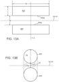
- FIG. 13A shows microelectrodes (402, 404) as each having a width (W) and length (L), with a gap (Lg) separating microelectrodes (402, 404).
- the width (W) of microelectrode (402) is equal to the width (W) of microelectrode (404); and the length (L) of microelectrode (402) is equal to the length (L) of microelectrode (404).
- Microelectrodes (402, 404) thus both have the same surface area (l*w) in the present example.
- Microelectrodes (402, 404) are oriented parallel to each other so that the two nearest substantially parallel surfaces (402a, 404a) define a longitudinal axis Le-Le for the microelectrode pair such as shown exemplarily in FIGS. 13A , 13C and 13D . In a preferred embodiment, shown in FIG.
- the microelectrodes (402, 404) are arranged such that the length (L) extends parallel to the longitudinal axis L-L of the structure to which microelectrodes (402, 404) are mounted (e.g., spines (42, 142), beams (222), flexible substrates (326), etc.); and such that the width (W) extends generally parallel to electrodes' longitudinal axis Le-Le or generally perpendicular to the longitudinal axis L-L of the structure to which microelectrodes (402, 404) are mounted.
- the length (L) extends parallel to the longitudinal axis L-L of the structure to which microelectrodes (402, 404) are mounted (e.g., spines (42, 142), beams (222), flexible substrates (326), etc.); and such that the width (W) extends generally parallel to electrodes' longitudinal axis Le-Le or generally perpendicular to the longitudinal axis L-L of the structure to which microelectrodes (402,
- Microelectrodes (402, 404) are positioned such that microelectrodes (402, 404) are spaced apart from each other along the length of the structure to which microelectrodes (402, 404), such that the gap (Lg) extends between the two nearest surfaces (402a, 404a) of the microelectrodes.
- the gap (Lg) is also taken to be substantially parallel to the longitudinal axis L-L of the structure to which microelectrodes (402, 404) are mounted.
- microelectrodes (402, 404) are rectangular in the present example, microelectrodes (402, 404) may instead have any other suitable shape. Various other suitable shapes will be apparent to those skilled in the art in view of the teachings herein.
- any arrangement of electrodes that would reduce or virtually remove fractionated signals, without signal processing applied to the sensed signals, may require the pair of electrodes to conform to the following empirical rules: (1) the length (L) of the electrode must always be at least the same as the spacing gap (Lg) between the pair of electrodes, and (2) the ratio of the area of the spacing gap (Ag) to the area of one electrode (Ae) must be less than or equal to 1. In short hand, this can be restated as: (1) L ⁇ Lg and (2) Ag/Ae ⁇ 1.
- Table 1 Various permutations of the electrode and gap configurations that may achieve the reduced signal fractionation (without signal processing) can be seen in Table 1.
- Electrode Width Electrode Length L
- Electrode Area (Ae in mm 2 ) Gap length Lg (mm) Area of Gap (Ag in mm 2 ) 1 st Aspect Ratio (L/Lg) 2 nd Aspect Ratio (Ag/Ae) 0.8 0.1 0.08 0.1 0.08 1 1 0.8 0.3 0.24 0.2 0.16 1.5 0.67 0.8 0.5 0.4 0.1 0.08 5 0.2 0.8 0.5 0.4 0.2 0.16 2.5 0.4 0.8 0.5 0.4 0.5 0.4 0.5 0.4 1 1 1 1 0.5 0.1 0.1 5 0.2 1 0.5 0.5 0.2 0.2 2.5 0.4 1 0.5 0.5 0.5 0.1 0.1 5 0.2 1 0.5 0.5 0.2 0.2 2.5 0.4 1 0.5 0.5 0.5 1 1 1 1 1 0.1 0.1 10 0.1 1 1 1 1 0.2 0.2 5 0.2 1 1 1 1 0.5 0.5 2 0.5
- the sensing and recording of electrocardiogram signals by the inventive electrode configurations are advantageous in that no special signal processing other than conventional low and high pass filters (obvious to those skilled in the art) need to be applied in order to present the electrocardiogram that has little or virtually no fractionated or far-field signals. It is believed that signal processing to reduce or eliminate far-field signals from sensed electrocardiogram are based on certain exclusion criteria that may not be applicable to the sensed signals and therefore the post-processed signal may not be an accurate representation of the signals locally produced by the cardiac tissue.
- each microelectrode (402, 404) may be approximately 0.4 squared millimeter or less; any surface area from approximately 0.05 squared millimeter to approximately 0.4 squared millimeter; any surface area from approximately 1 squared millimeter to approximately 0.4 squared millimeter.
- area or surface area is the amount of unit squares (in a suitable dimensional unit, e.g., millimeter) that can be contained or fitted within a two-dimensional planar boundary of the electrode.
- the term “area” or “surface area” excludes any meaning associated with "surface roughness”; “surface texture”; “fractal surface area”; or any measurement relating to a surface profile or fractals of such area.
- the area (or surface area) of the electrode is the area unrolled into a planar shape in two-dimension.
- the relevant "area” or “surface area” of such electrode is the planar surface in direct physical contact with the cardiac tissue.
- each microelectrode (402, 404) may be any length from approximately 100 microns to approximately 1 millimeter; any length from approximately 100 microns to approximately 300 microns; any length from approximately 300 microns to approximately 500 microns; or any length from approximately 500 microns to approximately 1 mm.
- each microelectrode (402, 404) may be any width from approximately 800 microns to approximately 1 mm; any width from approximately 800 microns to approximately 0.5 mm.
- each microelectrode (402, 404) may be any distance from approximately 50 microns to approximately 1 mm; any distance from approximately 50 microns to approximately 0.5 mm.
- each electrode of the electrode pair has a generally rectangular configuration with a dimension (width W) of about 800 microns as measured along the microelectrodes' longitudinal axis Le-Le (or as measured perpendicular to the longitudinal axis L-L) and a longitudinal dimension (length L) generally parallel to the axis L-L of about 300 microns to provide for one electrode surface area of about 0.24 squared-mm and a gap length (Lg) as measured between two nearest surfaces (402a, 404a) of respective microelectrodes.
- the gap length (Lg) can be seen as being generally perpendicular to the microelectrodes' longitudinal axis Le-Le (or generally parallel to the longitudinal axis L-L) of about 200 microns with a gap width being the same as the electrode width W for a gap surface area of about 160 microns.
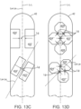
- the microelectrodes (402, 404) of FIG. 13A can be rotated about 90 degrees such that the microelectrodes' longitudinal axis Le-Le coincides (or parallel) with the longitudinal axis L-L of spine (42) as shown by microelectrodes (402', 404') in FIG. 13C .
- the orientation of the microelectrodes is not limited to a specific angle longitudinal axis Le-Le relative to the longitudinal axis L-L but can be at any orientation, such as shown for electrode pair (402", 404") or electrode pair (402′′′, 404′′′) in FIG. 13D as long as two nearest surfaces of respective microelectrode pair are substantially parallel.
- the electrode configuration such that the electrodes satisfy the empirical rule that the electrodes can be of any orientation (and number of electrodes) as long as at least two nearest surfaces of respective microelectrodes are substantially parallel with the gap distance Lg between the generally parallel surfaces. Specifically, for each group of electrodes, there can be at least two nearest surfaces that are generally in parallel to arrive at the gap Lg. For example, with respect to the top group of four electrodes (404′′′, 406, 402′′′, 408) in FIG.
- electrode (404′′′) has a surface generally parallel to a surface of electrode (406 or 408) to form a first pair (404′′′, 406) or second pair (404′′′, 408) with gap Lg for the first and second pairs; electrode (404′′′) has a surface generally parallel to surface of electrode (402′′′) to form a third electrode pair with gap Lg; electrode (406) has a surface generally parallel to electrode (402′′′) to form the fourth electrode pair.
- electrode (404′′′) has a surface generally parallel to a surface of electrode (406', 402′′′) to define gap Lg; electrode (406') has respective surfaces that are generally parallel to respective surfaces of electrode (404′′′, 402′′′) to define respective gaps Lg.
- a conversion factor CF may be used to determine the appropriate gap distance between the electrodes based on the known planar area of either one of the pair of electrodes.
- the conversion factor CF may range from about 2 to 0.1 in the inverse of the same root dimensional unit as the planar area of an electrode.
- the smallest gap distance (Lg) along the longitudinal axis extending through both electrodes can be determined by applying the conversion factor CF (in the inverse of the same root dimensional unit of the area or mm -1 ) to arrive at a gap distance Lg of about 100 microns.
- the conversion factor CF in the inverse of the same root dimensional unit or mm -1
- the conversion factor CF can be 1.25mm -1 or less, giving the range of the smallest gap distance Lg from about 300 microns to about 24 microns.
- a preferred conversion factor CF is about 0.83 (in the inverse of the same root dimensional unit for the electrode area).
- microelectrodes (402, 404) may prevent microelectrodes (402, 404) from picking up far field electrocardiogram signals (e.g., from the atria), such that microelectrodes (402, 404) only pick up electrocardiogram signals generated by the tissue in contact with microelectrodes (402, 404) (e.g., the pulmonary vein).
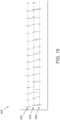
- FIG. 15 shows a graph (600) of three electrocardiogram signal plots (602, 604, 606) that are substantially free of fractionation, representing signals picked up by microelectrodes (402, 404) that are configured and arranged in accordance with the above teachings.
- plots (602, 604, 606) show voltages over time, as sensed by microelectrodes contacting tissue.
- plots (602, 604, 606) may represent electrocardiogram signals picked up by three different microelectrode pairs (400) that are positioned within the pulmonary vein of the patient.
- microelectrode pairs (400) are not picking up these far field signals, due to the configuration and arrangement of electrodes (402, 404) in each pair (400) as described above. Instead, the plots (602, 604, 606) show only the potentials from the associated regions of the pulmonary vein itself.
- An apparatus comprising: (a) a shaft; and (b) an end effector at a distal end of the shaft, wherein the end effector is sized to fit in an anatomical passageway within a subject's cardiovascular system, wherein the end effector comprises at least one electrode pair, wherein the at least one electrode pair is configured to contact cardiovascular tissue and thereby pick up electrocardiogram signals, wherein each electrode pair comprises: (i) a first electrode having a first surface area in a square dimensional unit, and (ii) a second electrode having the first surface area, wherein the first and second electrodes are spaced apart from each other by a gap distance, wherein the gap distance is defined by a multiplication of the first surface area to a conversion factor that ranges from approximately 0.1 to approximately 2 in the inverse of the square root of the same dimensional unit as the first surface area.
- Example 1 The apparatus of Example 1, wherein the end effector further comprises a plurality of elongated spines and a plurality of the electrode pairs, wherein the electrode pairs are secured to the spines.
- Example 2 wherein the shaft defines a longitudinal axis, wherein the spines extend outwardly away from the longitudinal axis, wherein the spines have respective free ends oriented away from the longitudinal axis.
- Example 2 The apparatus of Example 2, wherein the spines are configured to bow outwardly and converge distally to form a basket configuration.
- Example 2 wherein the end effector further comprises an inflatable member, wherein the spines are secured to an outer surface of the inflatable member.
- the gap distance comprises any distance from approximately 50 microns to approximately 3 mm.
- Example 8 The apparatus of Example 8, wherein the gap distance comprises any distance from approximately 50 microns to approximately 0.5 mm.
- the end effector comprises at least one electrode support member associated with the at least one electrode pair, wherein each electrode support member includes a first side and a second side, wherein the electrode pair is presented on only one of the sides of the corresponding electrode support member.
- bio-compatible metal comprises a metal selected from one of platinum, palladium, cobalt-chromium, nitinol, gold or any combinations thereof.
- the at least one electrode pair is configured to collect electrocardiogram signals of cardiac tissues that the electrode pair is in contact such that the electrocardiogram signals collected by the electrode pair are signals with significantly reduced fractionation during fibrillation of the cardiac tissues.
- the electrode surface area comprises any surface area from approximately 0.05 squared millimeter to approximately 1 squared millimeter and a gap length (Lg) from about 100 microns to about 500 microns.
- first and second electrodes are each rectangular, such that the first surface area is defined by a first length of the first and second electrodes and a first width of the first and second electrodes.
- Example 20 wherein the electrode pair comprises a configuration other than rectilinear planar shape.
- the gap distance comprises any distance from approximately 50 microns to approximately 3 mm.
- Example 26 The apparatus of Example 26, wherein the conversion factor is about 0.83 mm -1 .
- Example 26 The apparatus of Example 26, wherein the conversion factor is about 0.2 mm -1 .
- Example 26 wherein the conversion factor is about 0.4 mm -1 in the root dimension of the area of the electrode.
- Example 26 The apparatus of Example 26, wherein the conversion factor is about 1 mm -1 .
- Example 26 The apparatus of Example 26, wherein the conversion factor is about 0.5 mm -1 .
- the longitudinal axis comprises a longitudinal axis defined by two nearest substantially parallel surfaces of the microelectrodes.
- An apparatus comprising: (a) a shaft; and (b) an end effector at a distal end of the shaft, wherein the end effector is sized to fit in an anatomical passageway within a human cardiovascular system, wherein the end effector comprises at least one electrode pair, wherein the at least one electrode pair is configured to contact cardiovascular tissue and thereby pick up electrocardiogram signals, wherein each electrode pair comprises: (i) a first electrode having a first surface area of no greater than approximately 1 squared millimeters, and (ii) a second electrode having a second surface area, wherein the first and second electrodes are spaced apart from each other by a gap distance defined by two nearest substantially parallel surfaces of the respective first and second electrodes, wherein the gap distance (Lg) comprises any value from a product of one of the first surface or second surface area and a conversion factor no greater than about 1.25 mm -1 .
- Example 33 The apparatus of Example 33, wherein the second surface area is equal to the first surface area.
- the first surface area comprises an area selected from about 0.08 squared millimeter, 0.24 squared millimeter, 0.4 squared millimeter, 0.5 squared millimeter or 1 squared millimeter.
- the gap distance (Lg) comprises any distance from approximately 50 microns to approximately 500 microns.
- the gap distance comprises any distance from approximately 100 microns to approximately 200 microns.
- An apparatus comprising: (a) a shaft; and (b) an end effector at a distal end of the shaft, wherein the end effector is sized to fit in an anatomical passageway within a subject's cardiovascular system, wherein the end effector comprises at least one electrode pair, wherein the at least one electrode pair is configured to contact cardiovascular tissue and thereby pick up electrocardiogram signals, each electrode pair includes first and second electrodes spaced apart along a longitudinal axis from each other by a gap area (Ag) located between the electrodes, the gap area (Ag) having a gap length (Lg) with respect to the longitudinal axis such that: (i) a length of one of the electrodes (L) along the longitudinal axis is equal to or greater than the gap length; and (ii) a ratio of an area defined by the gap area (Ag) to one electrode area (Ae) is equal to or less than one.
- Example 41 in combination with any one or more of Examples 2 through 32.
- end effector (15, 117, 200, 300) is configured to provide RF ablation in addition to providing EP mapping functionality.
- end effector (15, 117, 200, 300) includes additional electrodes that are dedicated to providing RF ablation.
- Such RF ablation capabilities may be provided in accordance with the teachings of any of the various patent references cited herein. Alternatively, RF ablation capabilities may be omitted from end effector (15, 117, 200, 300).
- any of the examples described herein may include various other features in addition to or in lieu of those described above.
- any of the examples described herein may also include one or more of the various features disclosed in any of the various references that are cited herein.
Landscapes
- Health & Medical Sciences (AREA)
- Life Sciences & Earth Sciences (AREA)
- Surgery (AREA)
- Engineering & Computer Science (AREA)
- Public Health (AREA)
- Animal Behavior & Ethology (AREA)
- Veterinary Medicine (AREA)
- Physics & Mathematics (AREA)
- Biomedical Technology (AREA)
- Heart & Thoracic Surgery (AREA)
- Medical Informatics (AREA)
- Molecular Biology (AREA)
- General Health & Medical Sciences (AREA)
- Biophysics (AREA)
- Pathology (AREA)
- Cardiology (AREA)
- Physiology (AREA)
- Plasma & Fusion (AREA)
- Nuclear Medicine, Radiotherapy & Molecular Imaging (AREA)
- Otolaryngology (AREA)
- Surgical Instruments (AREA)
- Measurement And Recording Of Electrical Phenomena And Electrical Characteristics Of The Living Body (AREA)
Applications Claiming Priority (3)
| Application Number | Priority Date | Filing Date | Title |
|---|---|---|---|
| US201962819738P | 2019-03-18 | 2019-03-18 | |
| EP20723514.4A EP3941377B1 (de) | 2019-03-18 | 2020-03-17 | Elektrodenkonfigurationen zur diagnose von arrhythmien |
| PCT/IB2020/000174 WO2020188351A1 (en) | 2019-03-18 | 2020-03-17 | ELECTRODE CONFIGURATIONS FOR DIAGNOSIS OF ARRHYTHMlAS |
Related Parent Applications (1)
| Application Number | Title | Priority Date | Filing Date |
|---|---|---|---|
| EP20723514.4A Division EP3941377B1 (de) | 2019-03-18 | 2020-03-17 | Elektrodenkonfigurationen zur diagnose von arrhythmien |
Publications (2)
| Publication Number | Publication Date |
|---|---|
| EP4417119A2 true EP4417119A2 (de) | 2024-08-21 |
| EP4417119A3 EP4417119A3 (de) | 2024-11-20 |
Family
ID=70482707
Family Applications (2)
| Application Number | Title | Priority Date | Filing Date |
|---|---|---|---|
| EP24187456.9A Pending EP4417119A3 (de) | 2019-03-18 | 2020-03-17 | Elektrodenkonfigurationen zur diagnose von arrhythmien |
| EP20723514.4A Active EP3941377B1 (de) | 2019-03-18 | 2020-03-17 | Elektrodenkonfigurationen zur diagnose von arrhythmien |
Family Applications After (1)
| Application Number | Title | Priority Date | Filing Date |
|---|---|---|---|
| EP20723514.4A Active EP3941377B1 (de) | 2019-03-18 | 2020-03-17 | Elektrodenkonfigurationen zur diagnose von arrhythmien |
Country Status (6)
| Country | Link |
|---|---|
| US (3) | US11986320B2 (de) |
| EP (2) | EP4417119A3 (de) |
| JP (3) | JP7483856B2 (de) |
| CN (2) | CN120501438A (de) |
| IL (2) | IL286465B2 (de) |
| WO (1) | WO2020188351A1 (de) |
Families Citing this family (45)
| Publication number | Priority date | Publication date | Assignee | Title |
|---|---|---|---|---|
| US10905329B2 (en) | 2016-06-09 | 2021-02-02 | Biosense Webster (Israel) Ltd. | Multi-function conducting elements for a catheter |
| US12029545B2 (en) | 2017-05-30 | 2024-07-09 | Biosense Webster (Israel) Ltd. | Catheter splines as location sensors |
| US20190314083A1 (en) | 2018-04-11 | 2019-10-17 | Biosense Webster (Israel) Ltd. | Flexible Multi-Arm Catheter with Diametrically Opposed Sensing Electrodes |
| US11045628B2 (en) | 2018-12-11 | 2021-06-29 | Biosense Webster (Israel) Ltd. | Balloon catheter with high articulation |
| US11207016B2 (en) | 2018-12-28 | 2021-12-28 | Biosense Webster (Israel) Ltd. | Mapping ECG signals using a multipole electrode assembly |
| CN120501438A (zh) | 2019-03-18 | 2025-08-19 | 伯恩森斯韦伯斯特(以色列)有限责任公司 | 用于心律失常诊断的电极构型 |
| US11850051B2 (en) | 2019-04-30 | 2023-12-26 | Biosense Webster (Israel) Ltd. | Mapping grid with high density electrode array |
| US11712172B2 (en) | 2019-07-18 | 2023-08-01 | Biosense Webster (Israel) Ltd. | Visual guidance for positioning a distal end of a medical probe |
| US11759150B2 (en) | 2019-08-27 | 2023-09-19 | Biosense Webster (Israel) Ltd. | Accurate basket catheter tracking |
| US11950930B2 (en) | 2019-12-12 | 2024-04-09 | Biosense Webster (Israel) Ltd. | Multi-dimensional acquisition of bipolar signals from a catheter |
| US11517218B2 (en) | 2019-12-20 | 2022-12-06 | Biosense Webster (Israel) Ltd. | Selective graphical presentation of electrophysiological parameters |
| JP7640580B2 (ja) * | 2020-05-08 | 2025-03-05 | セント・ジュード・メディカル,カーディオロジー・ディヴィジョン,インコーポレイテッド | フレキシブル回路アセンブリを使用してスプラインを形成するための方法およびそれを含む電極アセンブリ |
| US12232874B2 (en) | 2020-05-29 | 2025-02-25 | Biosense Webster (Israel) Ltd. | Electrode apparatus for diagnosis of arrhythmias |
| US11987017B2 (en) | 2020-06-08 | 2024-05-21 | Biosense Webster (Israel) Ltd. | Features to assist in assembly and testing of devices |
| US12048479B2 (en) | 2020-09-10 | 2024-07-30 | Biosense Webster (Israel) Ltd. | Surface mounted electrode catheter |
| US11950841B2 (en) | 2020-09-22 | 2024-04-09 | Biosense Webster (Israel) Ltd. | Basket catheter having insulated ablation electrodes and diagnostic electrodes |
| US11950840B2 (en) | 2020-09-22 | 2024-04-09 | Biosense Webster (Israel) Ltd. | Basket catheter having insulated ablation electrodes |
| US12082875B2 (en) | 2020-09-24 | 2024-09-10 | Biosense Webster (Israel) Ltd | Balloon catheter having a coil for sensing tissue temperature and position of the balloon |
| WO2022072452A1 (en) | 2020-09-30 | 2022-04-07 | Boston Scientific Scimed Inc | Interactive 2d scatter plot of egm characteristic metrics |
| JP7585474B2 (ja) | 2020-09-30 | 2024-11-18 | ボストン サイエンティフィック サイムド,インコーポレイテッド | 局所サイクル長及び局所デューティサイクルを決定するための電気生理学システム及び方法 |
| US11974803B2 (en) | 2020-10-12 | 2024-05-07 | Biosense Webster (Israel) Ltd. | Basket catheter with balloon |
| US12201786B2 (en) | 2020-12-17 | 2025-01-21 | Biosense Webster (Israel) Ltd. | Measurement of distal end dimension of catheters using magnetic fields |
| US11918383B2 (en) | 2020-12-21 | 2024-03-05 | Biosense Webster (Israel) Ltd. | Visualizing performance of catheter electrodes |
| US12064170B2 (en) | 2021-05-13 | 2024-08-20 | Biosense Webster (Israel) Ltd. | Distal assembly for catheter with lumens running along spines |
| US12364426B2 (en) | 2021-08-12 | 2025-07-22 | Biosense Webster (Israel) Ltd. | Electro-anatomical mapping and annotation presented in electrophysiological procedures |
| US12004804B2 (en) | 2021-09-09 | 2024-06-11 | Biosense Webster (Israel) Ltd. | Basket catheter with mushroom shape distal tip |
| US12478424B2 (en) | 2021-09-10 | 2025-11-25 | Biosense Webster (Israel) Ltd. | Staggered pairs of biased ablation electrodes on basket catheter |
| US12011280B2 (en) | 2021-10-04 | 2024-06-18 | Biosense Webster (Israel) Ltd. | Electrophysiological mapping in the presence of injury current |
| US12533489B2 (en) | 2021-10-08 | 2026-01-27 | Biosense Webster (Israel) Ltd. | Measuring tissue proximity for multi-electrode catheter |
| US20230149069A1 (en) * | 2021-11-16 | 2023-05-18 | Biosense Webster (Israel) Ltd. | Planar catheter with overlapping electrode pairs |
| US20230190367A1 (en) | 2021-12-17 | 2023-06-22 | Biosense Webster (Israel) Ltd. | Catheter end effector with laterally projecting body |
| US12419683B2 (en) | 2021-12-22 | 2025-09-23 | Biosense Webster (Israel) Ltd. | Irreversible electroporation with shorted electrodes |
| US20230200895A1 (en) | 2021-12-27 | 2023-06-29 | Biosense Webster (Israel) Ltd. | Catheter end effector with resilient frame and flexible interior |
| US20230211118A1 (en) * | 2021-12-30 | 2023-07-06 | Biosense Webster (Israel) Ltd. | Soldering Leads to Pads in Producing Basket Catheter |
| US12484961B2 (en) | 2022-01-20 | 2025-12-02 | Biosense Webster (Israel) Ltd. | Mechanical retainer systems for electrodes of a basket catheter, and methods of the same |
| US12446946B2 (en) | 2022-01-20 | 2025-10-21 | Biosense Webster (Israel) Ltd. | Systems and methods for a single spiral electrode assembly forming a spherical basket for improved tissue contact and current delivery |
| US12440263B2 (en) | 2022-01-20 | 2025-10-14 | Biosense Webster (Israel) Ltd. | Systems and methods for tripodic spines forming a spherical basket for improved tissue contact and current delivery |
| US12465261B2 (en) | 2022-02-14 | 2025-11-11 | Biosense Webster (Israel) Ltd. | Filtering power line noises from analog electrophysiological signals in real-time |
| US12471989B2 (en) | 2022-04-28 | 2025-11-18 | Biosense Webster (Israel) Ltd. | Strengthened expandable baskets for medical probes and medical probes containing strengthen expandable baskets |
| US20240032845A1 (en) * | 2022-07-27 | 2024-02-01 | Biosense Webster (Israel) Ltd. | Method and system for identification of fractionated signals |
| US12533185B2 (en) | 2022-12-28 | 2026-01-27 | Biosense Webster (Israel) Ltd. | Basket end effector with distal position sensor |
| US20240216046A1 (en) * | 2022-12-29 | 2024-07-04 | Biosense Webster (Israel) Ltd. | Systems and methods for linear spines forming a spherical basket for improved tissue contact and current delivery |
| US12521035B2 (en) | 2022-12-29 | 2026-01-13 | Biosense Webster (Israel) Ltd. | Cylindrical cage systems and methods for distributed tissue contact for mapping and ablation |
| IL312953A (en) * | 2023-06-02 | 2025-01-01 | Biosense Webster Israel Ltd | Wrapped bilateral planar catheter |
| CN116746943B (zh) * | 2023-08-18 | 2023-11-07 | 四川锦江电子医疗器械科技股份有限公司 | 一种医用电极标测导管 |
Family Cites Families (41)
| Publication number | Priority date | Publication date | Assignee | Title |
|---|---|---|---|---|
| US5228442A (en) * | 1991-02-15 | 1993-07-20 | Cardiac Pathways Corporation | Method for mapping, ablation, and stimulation using an endocardial catheter |
| US5699796A (en) * | 1993-01-29 | 1997-12-23 | Cardima, Inc. | High resolution intravascular signal detection |
| US5411025A (en) | 1992-06-30 | 1995-05-02 | Cordis Webster, Inc. | Cardiovascular catheter with laterally stable basket-shaped electrode array |
| US5341807A (en) * | 1992-06-30 | 1994-08-30 | American Cardiac Ablation Co., Inc. | Ablation catheter positioning system |
| US5738096A (en) | 1993-07-20 | 1998-04-14 | Biosense, Inc. | Cardiac electromechanics |
| US5836874A (en) * | 1996-04-08 | 1998-11-17 | Ep Technologies, Inc. | Multi-function electrode structures for electrically analyzing and heating body tissue |
| US6123699A (en) | 1997-09-05 | 2000-09-26 | Cordis Webster, Inc. | Omni-directional steerable catheter |
| US6183463B1 (en) | 1997-12-01 | 2001-02-06 | Cordis Webster, Inc. | Bidirectional steerable cathether with bidirectional control handle |
| US6171277B1 (en) | 1997-12-01 | 2001-01-09 | Cordis Webster, Inc. | Bi-directional control handle for steerable catheter |
| US6198974B1 (en) | 1998-08-14 | 2001-03-06 | Cordis Webster, Inc. | Bi-directional steerable catheter |
| US6210407B1 (en) | 1998-12-03 | 2001-04-03 | Cordis Webster, Inc. | Bi-directional electrode catheter |
| US6267746B1 (en) | 1999-03-22 | 2001-07-31 | Biosense Webster, Inc. | Multi-directional steerable catheters and control handles |
| US6183435B1 (en) | 1999-03-22 | 2001-02-06 | Cordis Webster, Inc. | Multi-directional steerable catheters and control handles |
| AUPS226502A0 (en) | 2002-05-13 | 2002-06-13 | Advanced Metal Coatings Pty Limited | A multi-electrode lead |
| US20110190763A1 (en) * | 2010-01-29 | 2011-08-04 | Medtronic, Inc. | Needle Design for Recording Monophasic Action Potential and Delivery of Therapy |
| US8315696B2 (en) | 2010-12-09 | 2012-11-20 | Biosense Webster (Israel), Ltd. | Identifying critical CFAE sites using contact measurement |
| US9308041B2 (en) * | 2010-12-22 | 2016-04-12 | Biosense Webster (Israel) Ltd. | Lasso catheter with rotating ultrasound transducer |
| WO2012145073A1 (en) | 2011-04-22 | 2012-10-26 | Topera, Inc. | Basket style cardiac mapping catheter having spline bends for detection of cardiac rhythm disorders |
| JP5986441B2 (ja) * | 2012-07-06 | 2016-09-06 | キヤノン株式会社 | 静電容量型トランスデューサ |
| WO2014031865A1 (en) | 2012-08-22 | 2014-02-27 | Boston Scientific Scimed, Inc | High resolution map and ablate catheter |
| EP2890292B1 (de) | 2012-08-31 | 2021-01-13 | Acutus Medical, Inc. | Kathetersystem für das herz |
| US10098694B2 (en) * | 2013-04-08 | 2018-10-16 | Apama Medical, Inc. | Tissue ablation and monitoring thereof |
| US9480416B2 (en) | 2014-01-17 | 2016-11-01 | Biosense Webster (Israel) Ltd. | Signal transmission using catheter braid wires |
| US9956035B2 (en) | 2014-03-27 | 2018-05-01 | Biosense Webster (Israel) Ltd. | Temperature measurement in catheter |
| EP3151773B1 (de) * | 2014-06-04 | 2018-04-04 | Boston Scientific Scimed, Inc. | Elektrodenanordnung |
| EP3191164A4 (de) * | 2014-09-12 | 2018-08-15 | X-Rhythm, LLC | Mehrelektrodenabbildungssystem |
| WO2016061002A1 (en) * | 2014-10-13 | 2016-04-21 | Boston Scientific Scimed Inc. | Tissue diagnosis and treatment using mini-electrodes |
| US9788893B2 (en) | 2014-11-20 | 2017-10-17 | Biosense Webster (Israel) Ltd. | Catheter with soft distal tip for mapping and ablating tubular region |
| JP6686244B2 (ja) | 2015-03-17 | 2020-04-22 | 国立大学法人東北大学 | 電極素子及び電極の生産方法、並びに、当該電極を用いる測定システムの作製 |
| US9636164B2 (en) * | 2015-03-25 | 2017-05-02 | Advanced Cardiac Therapeutics, Inc. | Contact sensing systems and methods |
| US10575742B2 (en) * | 2015-06-30 | 2020-03-03 | Biosense Webster (Israel) Ltd. | Catheter having closed electrode assembly with spines of uniform length |
| US9907480B2 (en) * | 2016-02-08 | 2018-03-06 | Biosense Webster (Israel) Ltd. | Catheter spine assembly with closely-spaced bipole microelectrodes |
| KR101861783B1 (ko) * | 2016-02-26 | 2018-05-29 | 주식회사 스타메드 | 매핑 및 소작 카테터 |
| US10105179B2 (en) * | 2016-05-02 | 2018-10-23 | Affera, Inc. | Catheter sensing and irrigating |
| AU2017267505A1 (en) * | 2016-05-19 | 2019-01-17 | Dragon Medical Development Limited | Guidewire apparatus and method for multiple parameter analysis of Coronary stenosis |
| US10702177B2 (en) * | 2016-08-24 | 2020-07-07 | Biosense Webster (Israel) Ltd. | Catheter with bipole electrode spacer and related methods |
| US11172858B2 (en) * | 2016-10-28 | 2021-11-16 | St. Jude Medical, Cardiology Division, Inc. | Flexible high-density mapping catheter |
| EP3547910A4 (de) * | 2016-12-05 | 2020-07-15 | University of Vermont | Katheter, systeme und zugehörige verfahren zur abbildung, minimierung und behandlung von vorhofflimmern |
| US20180184982A1 (en) | 2017-01-05 | 2018-07-05 | Biosense Webster (Israel) Ltd. | Hybrid balloon basket catheter |
| US20180325586A1 (en) * | 2017-05-10 | 2018-11-15 | Boston Scientific Scimed Inc. | Single catheter for cardiac ablation and mapping |
| CN120501438A (zh) | 2019-03-18 | 2025-08-19 | 伯恩森斯韦伯斯特(以色列)有限责任公司 | 用于心律失常诊断的电极构型 |
-
2020
- 2020-03-17 CN CN202510416688.XA patent/CN120501438A/zh active Pending
- 2020-03-17 JP JP2022504740A patent/JP7483856B2/ja active Active
- 2020-03-17 US US16/820,848 patent/US11986320B2/en active Active
- 2020-03-17 EP EP24187456.9A patent/EP4417119A3/de active Pending
- 2020-03-17 IL IL286465A patent/IL286465B2/en unknown
- 2020-03-17 EP EP20723514.4A patent/EP3941377B1/de active Active
- 2020-03-17 WO PCT/IB2020/000174 patent/WO2020188351A1/en not_active Ceased
- 2020-03-17 CN CN202080037043.0A patent/CN113853175B/zh active Active
-
2024
- 2024-04-10 US US18/631,661 patent/US12502135B2/en active Active
- 2024-05-01 JP JP2024074292A patent/JP7724039B2/ja active Active
-
2025
- 2025-07-29 JP JP2025126293A patent/JP2025163096A/ja active Pending
- 2025-09-02 IL IL323096A patent/IL323096A/en unknown
- 2025-12-03 US US19/407,341 patent/US20260083401A1/en active Pending
Also Published As
| Publication number | Publication date |
|---|---|
| US20200297281A1 (en) | 2020-09-24 |
| IL286465B2 (en) | 2026-02-01 |
| JP7724039B2 (ja) | 2025-08-15 |
| EP3941377B1 (de) | 2024-07-10 |
| JP2025163096A (ja) | 2025-10-28 |
| US12502135B2 (en) | 2025-12-23 |
| US20260083401A1 (en) | 2026-03-26 |
| WO2020188351A1 (en) | 2020-09-24 |
| EP4417119A3 (de) | 2024-11-20 |
| US20240341688A1 (en) | 2024-10-17 |
| JP2022528810A (ja) | 2022-06-15 |
| CN113853175B (zh) | 2025-04-01 |
| EP3941377A1 (de) | 2022-01-26 |
| EP3941377C0 (de) | 2024-07-10 |
| IL286465B1 (en) | 2025-10-01 |
| JP2024099802A (ja) | 2024-07-25 |
| IL286465A (en) | 2021-10-31 |
| US11986320B2 (en) | 2024-05-21 |
| CN120501438A (zh) | 2025-08-19 |
| JP7483856B2 (ja) | 2024-05-15 |
| IL323096A (en) | 2025-11-01 |
| CN113853175A (zh) | 2021-12-28 |
Similar Documents
| Publication | Publication Date | Title |
|---|---|---|
| US12502135B2 (en) | Electrode configurations for diagnosis of arrhythmias | |
| US20230210432A1 (en) | Masked Ring Electrodes | |
| EP4353171B1 (de) | Blattkatheter mit hochdichter elektrodenanordnung | |
| EP4516227A2 (de) | Katheter mit dünnfilmelektroden auf einer dehnbaren mechanischen struktur | |
| US20210077184A1 (en) | Catheter with thin-film electrodes on expandable membrane | |
| EP2136702B1 (de) | Elektrophysiologischer katheter mit hoher auflösung | |
| EP4437989A2 (de) | Unipolare referenzelektrode für einen katheter zur elektrophysiologischen abbildung | |
| US20140058375A1 (en) | High resolution map and ablate catheter | |
| EP4640173A2 (de) | Herzkartierungskatheter mit quadratisch beabstandeten elektroden | |
| EP4201357A1 (de) | Katheterendeffektor mit elastischem rahmen und flexiblem innenraum | |
| EP4197472A1 (de) | Katheterendeffektor mit seitlich vorstehendem körper | |
| EP4406504B1 (de) | Elektrodendesigns für katheter |
Legal Events
| Date | Code | Title | Description |
|---|---|---|---|
| PUAI | Public reference made under article 153(3) epc to a published international application that has entered the european phase |
Free format text: ORIGINAL CODE: 0009012 |
|
| STAA | Information on the status of an ep patent application or granted ep patent |
Free format text: STATUS: THE APPLICATION HAS BEEN PUBLISHED |
|
| AC | Divisional application: reference to earlier application |
Ref document number: 3941377 Country of ref document: EP Kind code of ref document: P |
|
| AK | Designated contracting states |
Kind code of ref document: A2 Designated state(s): AL AT BE BG CH CY CZ DE DK EE ES FI FR GB GR HR HU IE IS IT LI LT LU LV MC MK MT NL NO PL PT RO RS SE SI SK SM TR |
|
| REG | Reference to a national code |
Ref country code: DE Ref legal event code: R079 Free format text: PREVIOUS MAIN CLASS: A61B0005053000 Ipc: A61B0018140000 |
|
| PUAL | Search report despatched |
Free format text: ORIGINAL CODE: 0009013 |
|
| AK | Designated contracting states |
Kind code of ref document: A3 Designated state(s): AL AT BE BG CH CY CZ DE DK EE ES FI FR GB GR HR HU IE IS IT LI LT LU LV MC MK MT NL NO PL PT RO RS SE SI SK SM TR |
|
| RIC1 | Information provided on ipc code assigned before grant |
Ipc: A61B 5/053 20210101ALN20241016BHEP Ipc: A61B 17/00 20060101ALI20241016BHEP Ipc: A61B 5/00 20060101ALI20241016BHEP Ipc: A61B 18/00 20060101ALI20241016BHEP Ipc: A61B 18/14 20060101AFI20241016BHEP |
|
| STAA | Information on the status of an ep patent application or granted ep patent |
Free format text: STATUS: REQUEST FOR EXAMINATION WAS MADE |
|
| 17P | Request for examination filed |
Effective date: 20250520 |
|
| STAA | Information on the status of an ep patent application or granted ep patent |
Free format text: STATUS: EXAMINATION IS IN PROGRESS |