EP4416352B1 - Hydraulisches ventil - Google Patents
Hydraulisches ventil Download PDFInfo
- Publication number
- EP4416352B1 EP4416352B1 EP22797851.7A EP22797851A EP4416352B1 EP 4416352 B1 EP4416352 B1 EP 4416352B1 EP 22797851 A EP22797851 A EP 22797851A EP 4416352 B1 EP4416352 B1 EP 4416352B1
- Authority
- EP
- European Patent Office
- Prior art keywords
- hydraulic valve
- hollow
- tank
- shutter
- opening
- Prior art date
- Legal status (The legal status is an assumption and is not a legal conclusion. Google has not performed a legal analysis and makes no representation as to the accuracy of the status listed.)
- Active
Links
Images

Classifications
-
- C—CHEMISTRY; METALLURGY
- C02—TREATMENT OF WATER, WASTE WATER, SEWAGE, OR SLUDGE
- C02F—TREATMENT OF WATER, WASTE WATER, SEWAGE, OR SLUDGE
- C02F1/00—Treatment of water, waste water, or sewage
- C02F1/72—Treatment of water, waste water, or sewage by oxidation
- C02F1/76—Treatment of water, waste water, or sewage by oxidation with halogens or compounds of halogens
-
- E—FIXED CONSTRUCTIONS
- E04—BUILDING
- E04H—BUILDINGS OR LIKE STRUCTURES FOR PARTICULAR PURPOSES; SWIMMING OR SPLASH BATHS OR POOLS; MASTS; FENCING; TENTS OR CANOPIES, IN GENERAL
- E04H4/00—Swimming or splash baths or pools
- E04H4/12—Devices or arrangements for circulating water, i.e. devices for removal of polluted water, cleaning baths or for water treatment
- E04H4/1209—Treatment of water for swimming pools
- E04H4/1236—Bottom drains
-
- F—MECHANICAL ENGINEERING; LIGHTING; HEATING; WEAPONS; BLASTING
- F16—ENGINEERING ELEMENTS AND UNITS; GENERAL MEASURES FOR PRODUCING AND MAINTAINING EFFECTIVE FUNCTIONING OF MACHINES OR INSTALLATIONS; THERMAL INSULATION IN GENERAL
- F16K—VALVES; TAPS; COCKS; ACTUATING-FLOATS; DEVICES FOR VENTING OR AERATING
- F16K1/00—Lift valves or globe valves, i.e. cut-off apparatus with closure members having at least a component of their opening and closing motion perpendicular to the closing faces
- F16K1/14—Lift valves or globe valves, i.e. cut-off apparatus with closure members having at least a component of their opening and closing motion perpendicular to the closing faces with ball-shaped valve member
-
- F—MECHANICAL ENGINEERING; LIGHTING; HEATING; WEAPONS; BLASTING
- F16—ENGINEERING ELEMENTS AND UNITS; GENERAL MEASURES FOR PRODUCING AND MAINTAINING EFFECTIVE FUNCTIONING OF MACHINES OR INSTALLATIONS; THERMAL INSULATION IN GENERAL
- F16K—VALVES; TAPS; COCKS; ACTUATING-FLOATS; DEVICES FOR VENTING OR AERATING
- F16K33/00—Floats for actuation of valves or other apparatus
-
- F—MECHANICAL ENGINEERING; LIGHTING; HEATING; WEAPONS; BLASTING
- F16—ENGINEERING ELEMENTS AND UNITS; GENERAL MEASURES FOR PRODUCING AND MAINTAINING EFFECTIVE FUNCTIONING OF MACHINES OR INSTALLATIONS; THERMAL INSULATION IN GENERAL
- F16T—STEAM TRAPS OR LIKE APPARATUS FOR DRAINING-OFF LIQUIDS FROM ENCLOSURES PREDOMINANTLY CONTAINING GASES OR VAPOURS
- F16T1/00—Steam traps or like apparatus for draining-off liquids from enclosures predominantly containing gases or vapours, e.g. gas lines, steam lines, containers
- F16T1/20—Steam traps or like apparatus for draining-off liquids from enclosures predominantly containing gases or vapours, e.g. gas lines, steam lines, containers with valves controlled by floats
- F16T1/22—Steam traps or like apparatus for draining-off liquids from enclosures predominantly containing gases or vapours, e.g. gas lines, steam lines, containers with valves controlled by floats of closed-hollow-body type
-
- C—CHEMISTRY; METALLURGY
- C02—TREATMENT OF WATER, WASTE WATER, SEWAGE, OR SLUDGE
- C02F—TREATMENT OF WATER, WASTE WATER, SEWAGE, OR SLUDGE
- C02F2103/00—Nature of the water, waste water, sewage or sludge to be treated
- C02F2103/42—Nature of the water, waste water, sewage or sludge to be treated from bathing facilities, e.g. swimming pools
-
- C—CHEMISTRY; METALLURGY
- C02—TREATMENT OF WATER, WASTE WATER, SEWAGE, OR SLUDGE
- C02F—TREATMENT OF WATER, WASTE WATER, SEWAGE, OR SLUDGE
- C02F2201/00—Apparatus for treatment of water, waste water or sewage
- C02F2201/002—Construction details of the apparatus
- C02F2201/005—Valves
-
- C—CHEMISTRY; METALLURGY
- C02—TREATMENT OF WATER, WASTE WATER, SEWAGE, OR SLUDGE
- C02F—TREATMENT OF WATER, WASTE WATER, SEWAGE, OR SLUDGE
- C02F2303/00—Specific treatment goals
- C02F2303/22—Eliminating or preventing deposits, scale removal, scale prevention
Definitions
- the present invention relates to a hydraulic valve that can be used in a tank to selectively intercept a delivery opening delimited at a bottom wall of the tank as a function of the level of liquid contained in the tank itself.
- hydraulic valve according to the invention can be used in alternative sectors with respect to the one indicated above, while providing for its use inside a tank or container in which a liquid is contained.
- Chlorine is an oxidizing and disinfectant substance and is highly effective against numerous pathogens that can spread in water.
- chlorine is a very irritating substance if inhaled or if it comes into contact with the skin and, for this reason, its concentration in the water must be kept within a predetermined range, in order to ensure correct disinfectant action without causing irritation.
- the chlorine concentration varies over time and, as far as possible, must be kept constant and within the aforementioned range.
- These devices provide for sucking a saturated chlorine solution contained in a tank, feeding it into the flow of water that is pumped into the pool.
- the tank is cyclically emptied to avoid the presence of deposits inside it and during the final stages of emptying it may happen that together with the chlorine saturated solution, air is sucked into the water pumped towards the pool, releasing bubbles inside the pool itself.
- such a float valve engages an opening which is delimited at a bottom of a tank and comprises a float selectively movable inside the valve relative to a discharge duct which extends through the valve itself and engages the through opening of the tank.
- the float is movable between an opening position, in which it is moved away from an inlet of the discharge pipe, freeing it and allowing the liquid to escape through the valve and a closed position in which the valve intercepts an inlet of the discharge pipe, occluding it.
- a drawback of such a valve concerns the inability to prevent the suction of air in the liquid that is sucked out of the tank in the final stage of emptying the tank, that is, when the level of the liquid to be sucked is close to running out.
- Document US 2010/071123A1 describes an apparatus configured to maintain the level of a liquid in a tank, in which the apparatus comprises a ball control valve positioned horizontally at a bottom portion of the tank and adapted to verify the passage of a flow.
- the purpose of the invention is to allow the aspiration of a liquid from a tank in a simple, efficient and practical way, preventing the formation of bubbles inside the liquid following the aspiration of air together with the liquid.
- a further purpose of the invention is to ensure correct suction of a liquid from a tank to allow a complete emptying of the tank itself.
- the specific object of the invention is a hydraulic valve connected to a bottom wall of a liquid containment tank, wherein the hydraulic valve engages a through opening delimited through the bottom wall, the hydraulic valve comprising a cage element connected to the bottom wall inside the tank, a shutter housed movable inside the cage element, in an interposed position between the cage element and the bottom wall, in which the hydraulic valve comprises a hollow connection element which engages the through opening is sealed by delimiting a passage which passes through the hydraulic valve to selectively place the tank in fluid communication with the outside according to the position of the obturator, in which the hollow connecting element comprises a portion of engagement which extends with one of its free ends into the through opening and defines a through opening which can be selectively closed by the obturator, in which the obturator is movable according to the liquid in the tank between a position distal to the free end, determining the opening of the hydraulic valve and a position of abutment against the free end of the hollow element connection, causing at least partial closure of the hydraulic
- the radial notches can be arranged equidistant from each other according to a circular symmetry with respect to a central symmetry axis of the hollow connection element.
- the radial notches can develop along the free end of the hollow connection element so as to be positioned below an internal surface of the back wall.
- the cage element is laterally delimited by a cylindrical wall, has an open bottom and a top closed by a lid, in which the lid is connected removably to the cylindrical wall or in which the lid is connected permanently to the cylindrical wall.
- the cylindrical wall can be crossed by a plurality of narrow and elongated shaped openings parallel to each other, the cage element acting as a filter for the passage of a liquid through it and preventing the passage of solid elements larger than a predetermined size, equal to a minimum passage section of the openings.
- the connecting hollow element comprises a connecting portion opposite the engagement portion, in which the connecting portion is configured to extend outside the bottom wall so as to provide an external hydraulic connection for the tank.
- the hollow connection element can comprise a shoulder configured as an annular element which protrudes externally from the hollow connection element, the shoulder being made in an interposed position between the engagement portion and the connecting portion connection.
- the shoulder can be positioned along the hollow connecting element so as to provide a stop for a flush positioning of the free end of the engagement portion with respect to an internal surface of the bottom wall, with the hollow connecting element in engagement in the through opening and the shoulder abutting against an external surface of the bottom wall.
- the shutter can be a hollow plastic ball.
- the hydraulic valve can comprise a hollow coupling insert that can be removably engaged in the hollow connection element at the free end portion, in which the hollow coupling insert delimits a central cavity through and protruding inside the tank, the hollow coupling insert has a head portion which acts as a selective abutment for the shutter in which the head portion occludes the through opening and has radial grooves which define respective channels which they keep the central through cavity in fluid communication with the inside of the tank when the shutter is in abutment against the head portion to allow a liquid introduced into the tank to be inserted below the shutter allowing its subsequent detachment relative to the hollow coupling insert during a tank filling.
- the hollow coupling insert can have support portions that act as a selective abutment for the shutter, in which the support portions are delimited between the radial grooves.
- the hydraulic valve according to the invention has a limited number of components and an overall simple structure that allows easy installation and implementation inside a tank.
- the hydraulic valve according to the invention includes a float shutter which determines its automatic activation according to the level of the liquid contained within the tank, without requiring any type of electrical power supply for the movement of a shutter.
- the hydraulic valve is configured to ensure correct operation even after repeated filling and emptying cycles of the tank in which it is installed, since it is practically free from jamming phenomena.
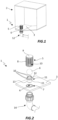
- the hydraulic valve 1 is configured to be connected to a tank 2 and, more precisely, to a bottom wall 3 of the tank 2, at a delimited opening 4 passing through the bottom wall 3 itself to selectively free or occlude a passage through this passing through opening 4.
- the passing through opening 4 is circular.
- a tank 2 comprising at least one hydraulic valve 1 is therefore object of the present invention.
- tank 2 is shown schematically, with particular reference to the bottom wall 3 to better promote the understanding of the hydraulic valve 1 itself.
- the hydraulic valve 1 comprises a cylindrical-shaped cage element 5 inside which a shutter 6 is housed which is movable between a raised position, away from the bottom wall 3 and a lowered position, near the bottom wall 3.
- the shutter 6 is configured as a spherical float. More precisely, the shutter 6 is a hollow plastic ball, although it is understood that alternative embodiments are possible in which the ball can be full or made of a different material capable of floating when immersed in a liquid.
- the cage element 5 is connected, in a removable way, to the bottom wall 3, inside the tank 2.
- the cage element 5 removably engages an annular seat 7 delimited at a bottom wall 3, concentric to the passing through opening 4.
- the cage element 5 is removably connected to the annular seat 7 via a snap or bayonet connection or with interference or via a threaded connection.
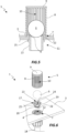
- the cage element 5 is laterally delimited by a cylindrical wall 8.
- the cage element 5 has an open bottom and a top closed by a lid 9.
- the cage element 5 is shaped like a glass or similar.
- the lid 9 is removably connected to the top of the cylindrical wall 8, for example by means of a snap or interference connection.
- the cover 9 can be removed to access the shutter 6 located inside the cage element 5 without requiring the removal of the entire cage element 5.
- the cylindrical wall 8 is crossed by a plurality of openings 10 which define passages through which a liquid contained in the tank 2 can flow, so as to pass through the hydraulic valve 1.
- the openings 10 are shaped narrow and elongated parallel to each other, so as to define narrow passages.
- the cage element 5 therefore acts as a filter capable of preventing any foreign bodies or solid residues present in the liquid from accessing the inside of the hydraulic valve 1.
- the hydraulic valve 1 comprises a hollow connection element 11 configured to engage the through opening 4 and provide a hydraulic connection for a pipe 12 or a pipeline or a hydraulic connection element to be connected to the tank 2.
- the hollow connection element 11 defines a passage that passes through the hydraulic valve 1 (see for example the sectional views shown in Figures 3 and 5 ).
- the hollow connection element 11 is configured to engage the through opening 4 delimited along the bottom wall 3, on a side opposite to that engaged by the cage element 5.
- the hollow connection element 11 is cylindrical and has an engagement portion 12 for sealing the through opening 4 and a connection portion 13, opposite the engagement portion 12, wherein the connection portion 13 is configured to extend outside the bottom wall 3 and provide a point for a hydraulic connection with a pipe 14 or a conduit or hydraulic connection element.
- the engagement portion 12 has a free end that acts as a stop for the shutter and defines a passage opening through which the inside of the tank 2 is placed in fluid communication with the outside.
- connection portion 13 is configured as a cylinder although it is understood that an alternative embodiment is possible, not shown in the attached Figures, in which the connection portion 13 has at least one threaded portion.
- the hollow connection element 11 has a shoulder 15, configured as an annular element that protrudes externally from the hollow connection element 11, in an interposed position between the engagement portion 12 and the connection portion 13.
- the shoulder 15 acts as an abutment against the bottom wall 3, to allow correct positioning of the hollow connection element 11 relative to the bottom wall 3.
- the hollow connection element 11 when it is arranged in engagement with the through opening 4, with the shoulder 15 abutting against an external surface of the bottom wall 3, has the free end of the engagement portion 12 positioned flush or substantially flush with an internal surface of the bottom wall 3 (see for example Figure 4 ).
- the free end of the engagement portion 12, as mentioned, acts as an abutment for the shutter 6 which, therefore, does not come into contact with the bottom wall 3.
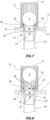
- the hollow connection element 11 has a plurality of radial notches 16 which pass through radially at the free end of the engagement portion 12 and delimit the respective passageways through the engagement portion 12.
- the free end of the engagement portion 12 therefore has a plurality of appendages mutually separated by the radial notches 16, in which the appendages provide abutments for the shutter 6.
- the hollow connection element 11 has four radial notches 16 arranged equidistant from each other according to a circular symmetry with respect to a central symmetry axis of the hollow connection element 11. It is understood that alternative embodiments of the hollow connection element 11 comprising a greater or lesser number of radial notches 16 than previously described, wherein the radial notches 16 are in any case arranged equidistant from each other according to a circular symmetry.
- the radial notches 16 allow a progressive closure of the hydraulic valve 1 allowing the liquid contained in the tank 2 to escape during the final stages of emptying, so as to hinder the creation of vortices with the consequent suction of air through the hydraulic valve 1.
- the radial notches 16 delimit preferential passages for a liquid that comes out of the tank 2, in which these passages are positioned below the internal surface of the bottom wall 3 and are open at their top end.
- the radial notches 16 delimit preferential passages for the liquid leaving the tank 2 during the approach of the shutter 6 to the free end portion of the engagement portion 12, since the shutter 6 in this configuration determines a progressive narrowing of the passage opening of the hollow connection element 11.
- the hollow connection element 11 has a flare at the free end of the engagement portion 12, in which this flare extends along each of the appendages present along this free end.
- the flaring allows to increase the contact surface between the engagement portion 12 and the shutter 6, promoting the maintenance of the latter in position when it is lowered and against the hollow connection element 11.
- the shutter 6 is moved in the raised position inside the cage element 5 when the tank 2 is filled with a liquid.
- the shutter 6 in the raised position is moved away from the bottom wall 3 and from the hollow connection element 11, thus freeing the passage opening centrally delimited in the latter and placing the hydraulic valve 1 in the open configuration.
- the liquid advances by gravity through the hollow connection element 11, resulting in the emptying of the tank 2 and the lowering of the free surface of the liquid contained within it.
- the shutter 6 is kept in a completely raised position, i.e. with the shutter 6 abutting against the lid 9 of the cage element 5, as long as the free surface of the liquid inside the tank 2 is such as to determine the floatation of the shutter 6 in this position.
- the progressive emptying of the tank 2 determines the lowering of the shutter 6 inside the cage element 5.
- the emptying of the tank 2 can occur by means of a depression caused downstream of a hydraulic circuit connected to the pipe 14, not illustrated in the attached Figures, which, in turn, is connected to the hydraulic valve 1 through the hollow connection element 11, as better described below.
- a hydraulic circuit connected to the pipe 14 not illustrated in the attached Figures, which, in turn, is connected to the hydraulic valve 1 through the hollow connection element 11, as better described below.
- the shutter 6 In the final stages of emptying the tank 2, in which the free surface of the liquid inside the tank is in close proximity to the bottom wall 3, the shutter 6 approaches the free end of the engagement portion 12, progressively reducing the free section for the passage of liquid through the hydraulic valve 1.
- This configuration is determined by a minimum presence of liquid inside the tank 2 able to keep the shutter 6 slightly raised with respect to the bottom wall 3 and, in particular, with respect to the hollow connection element 11.
- the radial notches 16 delimit preferential passages for the liquid which tends to fill them, preventing the passage of air through them.
- the hydraulic valve 1 comprises a hollow coupling insert 17 that can be removably engaged in the hollow connection element 11, at the free end portion of the engagement portion 12 (see Figures 6-8 ).
- the hollow coupling insert 17 acts as a selective abutment for the shutter 6 for the purposes that will be described below.
- the hollow coupling insert 17 is used when the hydraulic valve 1 is operatively connected to a suction circuit, not shown in the attached Figures. According to this configuration, the outflow of the liquid from the tank 2 is selectively controlled by means of a vacuum through the pipe 14 to which the hydraulic valve 1 is connected in fluid communication and the hollow coupling insert 17 is configured to maintain at least one passage opening minimum relative to the shutter 6 to allow the detachment of the shutter 6 during a filling phase subsequent to a phase of complete emptying of the tank 2.
- the hollow coupling insert 17 has a central passing through cavity 18 to allow the passage of the sucked liquid through the hollow coupling insert 17 and the hollow connection element 11 to which it is connected (see Figures 7 and 8 ).
- the hollow coupling insert 17 has a circular symmetry and a circular footprint.
- the hollow coupling insert 17 has an external diameter greater than the diameter of the through opening 4 in order to occlude it, for the purposes that will be described below.
- the hollow coupling insert 17 has a head portion 19, configured annular or substantially annular, and a coupling portion 20 that protrudes from a bottom of the head portion 19.
- the head portion 19 is configured to act selectively as an abutment to the shutter 6, depending on the position assumed by the shutter 6 itself inside the cage element 5.
- the coupling portion 20 is configured to engage the free end of the top of the engagement portion 12 of the hollow connection element 11, thus allowing the reciprocal connection between the hollow coupling insert 17 and the hollow connection element 11.
- the coupling portion 20 is cylindrical and has a smaller external diameter than that of the head portion 19. Following the engagement of the coupling portion 20 in the hollow connection element 11, the head portion 19 abuts against the free end of the engagement portion 12 of the hollow connection element 11, constraining the hollow coupling insert 17 in position.
- the head portion 19 occludes the central opening 4 and the radial notches 16 on which it is positioned.
- the hollow coupling insert 17 has a sealing seat 21 delimited along the coupling portion 20, configured to at least partially house an annular sealing element 22, preferably an O-ring or an annular gasket, so that a portion of this annular sealing element 22 extends outside the coupling portion 20 defining a seal for the connection between the hollow coupling insert 17 and the hollow connection element 11.
- the hollow coupling insert 17 has radial grooves 23 that partially extend through the head portion 19.
- the radial grooves 23 define respective channels which extend through the head portion 19 and are in fluid communication with the central passing through cavity 18.
- the hollow coupling insert 17 shown in the attached Figures 6-8 has four radial grooves 23 arranged equidistant from each other according to a circular symmetry with respect to a central symmetry axis of the hollow coupling insert 17. It is understood that alternative embodiments of the hollow coupling insert 17 comprising a greater or lesser number of radial grooves 23 than previously described, wherein the radial grooves 23 are in any case arranged equidistant from each other according to a circular symmetry.
- the hollow coupling insert 17 therefore has at the head portion 19 support portions 24 delimited between the radial grooves 23.
- the support portions 24 provide an abutment for the shutter 6, when this is not supported by any liquid inside the tank 2.
- the radial grooves 23 extend partially through the head portion 19, starting from a top of the head portion 19 itself and ending before a bottom of the head portion 19 itself.
- the hollow coupling insert 17 is crossed by a central passing through cavity 18 which defines an inlet opening 25 at the top of the head portion 19.
- the inlet opening 25 is flared to promote at least partial housing of the shutter 6.
- hollow coupling insert 17 is configured to maintain at least one passageway when the shutter 6 is fully supported at the head portion 19, as shown in the attached Figure 7 .
- the hollow coupling insert 17 keeping the shutter 6 in a spaced position with respect to the central passing through cavity 18 guarantees the detachment of the shutter 6 itself after emptying the tank 2.
- the liquid is able to enter the central passing through cavity 18 through the radial grooves 23, inserting itself below the shutter 6 in order to then be able to lift it and move it away from the hollow coupling insert during the further tank filling 2.
- the radial grooves 23 perform the same function as the radial slots 16 in relation to the possibility of preventing the formation of vortices at the hydraulic valve 1 and therefore the intake of air inside the hydraulic valve 1 itself and the liquid sucked through it.
- the radial notches 16 delimited in the hydraulic valve 1 define respective ports for the passage of liquid in the final stages of emptying the tank 2, through which the passage of the liquid that is sucked through the hydraulic valve 1 is allowed, preventing the intake of air which is inhibited by the shutter 6.
- the hydraulic valve 1 therefore, allows to avoid the aspiration and mixing of air in a liquid that is sucked out from a tank 2, thus overcoming a drawback that afflicts traditional solutions.
Landscapes
- Engineering & Computer Science (AREA)
- General Engineering & Computer Science (AREA)
- Architecture (AREA)
- Mechanical Engineering (AREA)
- Water Supply & Treatment (AREA)
- Structural Engineering (AREA)
- Civil Engineering (AREA)
- Life Sciences & Earth Sciences (AREA)
- Hydrology & Water Resources (AREA)
- Environmental & Geological Engineering (AREA)
- Chemical & Material Sciences (AREA)
- Organic Chemistry (AREA)
- Supply Devices, Intensifiers, Converters, And Telemotors (AREA)
- Lift Valve (AREA)
- Valve Device For Special Equipments (AREA)
Claims (11)
- Hydraulikventil (1), das mit einer Bodenwand (3) eines Behälters (2) zum Enthalten einer Flüssigkeit verbunden ist, wobei das Hydraulikventil (1) in eine Durchgangsöffnung (4) eingesetzt ist, die durch die Bodenwand (3) begrenzt ist, wobei das Hydraulikventil (1) ein Käfigelement (5) umfasst, das mit der Bodenwand (3) innerhalb des Behälters (2) verbunden ist,einen Verschluss (6), der innerhalb des Käfigelements (5) in einer Zwischenposition zwischen dem Käfigelement (5) und der Bodenwand (3) beweglich untergebracht ist, dadurch gekennzeichnet, dass das Hydraulikventil (1) ein hohles Verbindungselement (11) umfasst, das hermetisch in die Durchgangsöffnung (4) eingesetzt ist und einen Durchgang begrenzt, der durch das Hydraulikventil (1) verläuft, um den Behälter (2) gemäß der Position des Verschlusses (6) selektiv in Fluidverbindung mit der Außenseite zu bringen,wobei das hohle Verbindungselement (11) einen Eingriffsabschnitt (12) aufweist, der sich mit einem seiner freien Enden in die Durchgangsöffnung (4) erstreckt und eine Durchgangsöffnung definiert, die durch den Verschluss (6) selektiv verschließbar ist, wobei der Verschluss (6) gemäß der Flüssigkeit in dem Behälter (2) zwischen einer Position distal zu dem freien Ende, die das Öffnen des Hydraulikventils (1) bewirkt, und einer Anschlagsposition gegen das freie Ende des hohlen Verbindungselements (11) beweglich ist, was zumindest ein teilweises Schließen des Hydraulikventils (1) bewirkt,wobei das hohle Verbindungselement (11) radiale Kerben (16) aufweist, die radial durch das freie Ende des Eingriffsabschnitts (12) verlaufen, und, wenn sich der Verschluss (6) nah des freien Endes befindet, die radialen Kerben (16) jeweilige bevorzugte Durchgänge für eine Flüssigkeit definieren, die aus dem Behälter (2) gesaugt wird, was das allmähliche Schließen des Hydraulikventils (1) bestimmt und die Bildung von Wirbeln und ein Ansaugen von Luft durch das hohle Verbindungselement (11) vermeidet.
- Hydraulikventil (1) nach Anspruch 1, wobei die radialen Kerben (16) in gleichen Abständen voneinander gemäß einer Kreissymmetrie in Bezug auf eine zentrale Symmetrieachse des hohlen Verbindungselements (11) angeordnet sind.
- Hydraulikventil (1) nach Anspruch 1 oder 2, wobei sich die radialen Kerben (16) entlang des freien Endes des hohlen Verbindungselements (11) erstrecken, so dass sie unterhalb einer Innenfläche der Bodenwand (3) an der Durchgangsöffnung (4) positioniert sind.
- Hydraulikventil (1) nach Anspruch 1, wobei das Käfigelement (5) durch eine zylindrische Wand (8) seitlich begrenzt ist, einen offenen Boden und eine Oberseite aufweist, die durch einen Deckel (9) verschlossen ist, wobei der Deckel (9) mit der zylindrischen Wand (8) entfernbar verbunden ist oder wobei der Deckel (9) dauerhaft mit der zylindrischen Wand (8) verbunden ist.
- Hydraulikventil (1) nach Anspruch 4, wobei die zylindrische Wand (8) von einer Vielzahl von schmalen und länglich geformten Öffnungen (10) durchgedrungen wird, die parallel zueinander sind, wobei das Käfigelement (5) als ein Filter für den Durchfluss einer Flüssigkeit dadurch wirkt und den Durchgang von festen Elementen verhindert, die größer als eine vorbestimmte Abmessung sind, die gleich einem minimalen Durchgangsquerschnitt der Öffnungen (10) ist.
- Hydraulikventil (1) nach einem der vorhergehenden Ansprüche, wobei das hohle Verbindungselement (11) einen Verbindungsabschnitt (13) aufweist, der dem Eingriffsabschnitt (12) gegenüberliegt, wobei der Verbindungsabschnitt (13) konfiguriert ist, um sich außerhalb der Bodenwand (3) zu erstrecken, um eine externe Hydraulikverbindung für den Behälter (2) bereitzustellen.
- Hydraulikventil (1) nach Anspruch 6, wobei das hohle Verbindungselement (11) eine Schulter (15) aufweist, die als ein ringförmiges Element konfiguriert ist, das sich von dem hohlen Verbindungselement (11) nach außen erstreckt, wobei die Schulter (15) in einer Zwischenposition zwischen dem Eingriffsabschnitt (12) und dem Verbindungsabschnitt (13) ausgebildet ist.
- Hydraulikventil (1) nach Anspruch 7, wobei die Schulter (15) entlang des hohlen Verbindungselements (11) positioniert ist, um einen Anschlag für eine bündige Positionierung des freien Endes des Eingriffsabschnitts (12) in Bezug auf eine Innenfläche der Bodenwand (3) bereitzustellen, wobei das hohle Verbindungselement (11) in der Durchgangsöffnung (4) in Eingriff ist und die Schulter (15) an einer Außenfläche der Bodenwand (3) anliegt.
- Hydraulikventil (1) nach einem der vorhergehenden Ansprüche, wobei der Verschluss (6) eine hohle Kunststoffkugel ist.
- Hydraulikventil (1) nach einem der vorhergehenden Ansprüche, das einen hohlen Kupplungseinsatz (17) aufweist, der in dem hohlen Verbindungselement (11) an dem freien Endabschnitt entfernbar eingreifbar ist, wobei der Kupplungseinsatz (17) einen zentralen Durchgangshohlraum (18) begrenzt und einen Kopfabschnitt (19) aufweist, der als ein selektiver Anschlag für den Verschluss (6) wirkt, wobei der Kopfabschnitt (19) die Durchgangsöffnung (4) verschließt und radiale Nuten (23) aufweist, die jeweilige Kanäle definieren, die den zentralen Durchgangshohlraum (18) in Fluidverbindung mit dem Inneren des Behälters (2) halten, wenn der Verschluss (6) an dem Kopfabschnitt (19) anliegt, um zu ermöglichen, dass eine in den Behälter (2) eingeführte Flüssigkeit unter den Verschluss (6) eingeführt wird, was ihr anschließendes Lösen in Bezug auf den hohlen Kupplungseinsatz (17) ermöglicht.
- Hydraulikventil (1) nach Anspruch 10, wobei der hohle Kupplungseinsatz (17) Stützabschnitte (24) aufweist, die als ein selektiver Anschlag für den Verschluss (6) wirken, wobei die Stützabschnitte (24) zwischen den radialen Nuten (23) begrenzt sind.
Applications Claiming Priority (2)
| Application Number | Priority Date | Filing Date | Title |
|---|---|---|---|
| IT102021000026159A IT202100026159A1 (it) | 2021-10-12 | 2021-10-12 | Valvola idraulica |
| PCT/IB2022/059729 WO2023062526A1 (en) | 2021-10-12 | 2022-10-11 | Hydraulic valve |
Publications (3)
| Publication Number | Publication Date |
|---|---|
| EP4416352A1 EP4416352A1 (de) | 2024-08-21 |
| EP4416352C0 EP4416352C0 (de) | 2025-05-28 |
| EP4416352B1 true EP4416352B1 (de) | 2025-05-28 |
Family
ID=79018591
Family Applications (1)
| Application Number | Title | Priority Date | Filing Date |
|---|---|---|---|
| EP22797851.7A Active EP4416352B1 (de) | 2021-10-12 | 2022-10-11 | Hydraulisches ventil |
Country Status (5)
| Country | Link |
|---|---|
| US (1) | US12492567B2 (de) |
| EP (1) | EP4416352B1 (de) |
| AU (1) | AU2022367926A1 (de) |
| IT (1) | IT202100026159A1 (de) |
| WO (1) | WO2023062526A1 (de) |
Family Cites Families (8)
| Publication number | Priority date | Publication date | Assignee | Title |
|---|---|---|---|---|
| US1501620A (en) * | 1921-11-16 | 1924-07-15 | Reed Dudley | Flushing tank |
| US1553616A (en) * | 1923-11-03 | 1925-09-15 | Mark W Johnson | Hydraulic flushing valve for water-closet tanks |
| US2800664A (en) * | 1956-09-05 | 1957-07-30 | Arthur H Bridge | Toilet flush valve and operating mechanism therefor |
| US3418789A (en) * | 1965-08-30 | 1968-12-31 | Norgren Co C A | Automatic liquid discharge mechanism |
| FR1463726A (fr) * | 1966-01-18 | 1966-12-23 | Perfectionnements aux prises de fond pour piscines | |
| US4499615A (en) * | 1980-07-14 | 1985-02-19 | Radovsky Everett S | Flush and refill device |
| US6408452B1 (en) * | 2000-04-21 | 2002-06-25 | Arthur J. Bromley | Automatic shut-off valve |
| US8875731B2 (en) * | 2008-09-24 | 2014-11-04 | David Larsen | Automatic water leveler |
-
2021
- 2021-10-12 IT IT102021000026159A patent/IT202100026159A1/it unknown
-
2022
- 2022-10-11 AU AU2022367926A patent/AU2022367926A1/en active Pending
- 2022-10-11 US US18/697,041 patent/US12492567B2/en active Active
- 2022-10-11 EP EP22797851.7A patent/EP4416352B1/de active Active
- 2022-10-11 WO PCT/IB2022/059729 patent/WO2023062526A1/en not_active Ceased
Also Published As
| Publication number | Publication date |
|---|---|
| WO2023062526A1 (en) | 2023-04-20 |
| IT202100026159A1 (it) | 2023-04-12 |
| EP4416352A1 (de) | 2024-08-21 |
| AU2022367926A1 (en) | 2024-05-16 |
| EP4416352C0 (de) | 2025-05-28 |
| US12492567B2 (en) | 2025-12-09 |
| US20250075522A1 (en) | 2025-03-06 |
Similar Documents
| Publication | Publication Date | Title |
|---|---|---|
| US6662379B2 (en) | Toilet cleaning dispenser system with removable cartridge | |
| RU2667862C2 (ru) | Обратный клапан | |
| CS214808B2 (en) | Closing valve | |
| EP1167848B1 (de) | Schwimmerventil mit zwei Trichtern | |
| CN113790288A (zh) | 阀门和试剂盒 | |
| EP4416352B1 (de) | Hydraulisches ventil | |
| US6481455B2 (en) | Bubble trap for blood | |
| JPH03132530A (ja) | 洗浄タンク | |
| KR20200001669U (ko) | 에어 차단기능을 갖는 드립챔버 | |
| CN113790287A (zh) | 驱动机构和阀门 | |
| FI78542B (fi) | Ventil foer sugsystem. | |
| CN218152490U (zh) | 阀门和试剂盒 | |
| KR101726233B1 (ko) | 수액세트용 에어 차단장치 | |
| KR101742090B1 (ko) | 에어 차단기능을 갖는 드립챔버 | |
| US20190002170A1 (en) | Liquid extraction, storage, and dispensing system and method of use | |
| CN215211444U (zh) | 一种人防工程用防毒防爆地漏 | |
| CN223569767U (zh) | 便于残留液体处理的自动中断输液装置 | |
| KR100323046B1 (ko) | 정수장 및 폐수 처리장 일축 일체형 다종 액체 약품 투입 장치 | |
| EP0053932A1 (de) | Methode zum Transportieren von Flüssigkeiten | |
| CN223654266U (zh) | 一种自排气环柄注射器 | |
| KR200192314Y1 (ko) | 자동공기변 | |
| CN109481795B (zh) | 一种双重止液自排气安全滴斗 | |
| RU2005141C1 (ru) | Дозатор жидкости | |
| RU160493U1 (ru) | Автоматический газоотводчик для гидравлических сетей | |
| SU1065544A1 (ru) | Устройство дл откачки жидкостей |
Legal Events
| Date | Code | Title | Description |
|---|---|---|---|
| STAA | Information on the status of an ep patent application or granted ep patent |
Free format text: STATUS: UNKNOWN |
|
| STAA | Information on the status of an ep patent application or granted ep patent |
Free format text: STATUS: THE INTERNATIONAL PUBLICATION HAS BEEN MADE |
|
| PUAI | Public reference made under article 153(3) epc to a published international application that has entered the european phase |
Free format text: ORIGINAL CODE: 0009012 |
|
| STAA | Information on the status of an ep patent application or granted ep patent |
Free format text: STATUS: REQUEST FOR EXAMINATION WAS MADE |
|
| 17P | Request for examination filed |
Effective date: 20240329 |
|
| AK | Designated contracting states |
Kind code of ref document: A1 Designated state(s): AL AT BE BG CH CY CZ DE DK EE ES FI FR GB GR HR HU IE IS IT LI LT LU LV MC ME MK MT NL NO PL PT RO RS SE SI SK SM TR |
|
| P01 | Opt-out of the competence of the unified patent court (upc) registered |
Free format text: CASE NUMBER: APP_63833/2024 Effective date: 20241202 |
|
| DAV | Request for validation of the european patent (deleted) | ||
| DAX | Request for extension of the european patent (deleted) | ||
| REG | Reference to a national code |
Ref country code: DE Ref legal event code: R079 Free format text: PREVIOUS MAIN CLASS: E04H0004120000 Ipc: C02F0103420000 Ref country code: DE Ref legal event code: R079 Ref document number: 602022015274 Country of ref document: DE Free format text: PREVIOUS MAIN CLASS: E04H0004120000 Ipc: C02F0103420000 |
|
| GRAP | Despatch of communication of intention to grant a patent |
Free format text: ORIGINAL CODE: EPIDOSNIGR1 |
|
| STAA | Information on the status of an ep patent application or granted ep patent |
Free format text: STATUS: GRANT OF PATENT IS INTENDED |
|
| RIC1 | Information provided on ipc code assigned before grant |
Ipc: F16T 1/22 20060101ALI20250212BHEP Ipc: F16K 33/00 20060101ALI20250212BHEP Ipc: F16K 1/14 20060101ALI20250212BHEP Ipc: E04H 4/12 20060101ALI20250212BHEP Ipc: C02F 1/76 20230101ALI20250212BHEP Ipc: C02F 103/42 20060101AFI20250212BHEP |
|
| INTG | Intention to grant announced |
Effective date: 20250303 |
|
| GRAS | Grant fee paid |
Free format text: ORIGINAL CODE: EPIDOSNIGR3 |
|
| GRAA | (expected) grant |
Free format text: ORIGINAL CODE: 0009210 |
|
| STAA | Information on the status of an ep patent application or granted ep patent |
Free format text: STATUS: THE PATENT HAS BEEN GRANTED |
|
| AK | Designated contracting states |
Kind code of ref document: B1 Designated state(s): AL AT BE BG CH CY CZ DE DK EE ES FI FR GB GR HR HU IE IS IT LI LT LU LV MC ME MK MT NL NO PL PT RO RS SE SI SK SM TR |
|
| REG | Reference to a national code |
Ref country code: GB Ref legal event code: FG4D |
|
| REG | Reference to a national code |
Ref country code: CH Ref legal event code: EP |
|
| REG | Reference to a national code |
Ref country code: IE Ref legal event code: FG4D Ref country code: DE Ref legal event code: R096 Ref document number: 602022015274 Country of ref document: DE |
|
| U01 | Request for unitary effect filed |
Effective date: 20250623 |
|
| U07 | Unitary effect registered |
Designated state(s): AT BE BG DE DK EE FI FR IT LT LU LV MT NL PT RO SE SI Effective date: 20250701 |
|
| P04 | Withdrawal of opt-out of the competence of the unified patent court (upc) registered |
Free format text: CASE NUMBER: APP_30996/2025 Effective date: 20250627 |
|
| PG25 | Lapsed in a contracting state [announced via postgrant information from national office to epo] |
Ref country code: ES Free format text: LAPSE BECAUSE OF FAILURE TO SUBMIT A TRANSLATION OF THE DESCRIPTION OR TO PAY THE FEE WITHIN THE PRESCRIBED TIME-LIMIT Effective date: 20250528 |
|
| PG25 | Lapsed in a contracting state [announced via postgrant information from national office to epo] |
Ref country code: GR Free format text: LAPSE BECAUSE OF FAILURE TO SUBMIT A TRANSLATION OF THE DESCRIPTION OR TO PAY THE FEE WITHIN THE PRESCRIBED TIME-LIMIT Effective date: 20250829 Ref country code: NO Free format text: LAPSE BECAUSE OF FAILURE TO SUBMIT A TRANSLATION OF THE DESCRIPTION OR TO PAY THE FEE WITHIN THE PRESCRIBED TIME-LIMIT Effective date: 20250828 |
|
| PG25 | Lapsed in a contracting state [announced via postgrant information from national office to epo] |
Ref country code: PL Free format text: LAPSE BECAUSE OF FAILURE TO SUBMIT A TRANSLATION OF THE DESCRIPTION OR TO PAY THE FEE WITHIN THE PRESCRIBED TIME-LIMIT Effective date: 20250528 |
|
| PG25 | Lapsed in a contracting state [announced via postgrant information from national office to epo] |
Ref country code: HR Free format text: LAPSE BECAUSE OF FAILURE TO SUBMIT A TRANSLATION OF THE DESCRIPTION OR TO PAY THE FEE WITHIN THE PRESCRIBED TIME-LIMIT Effective date: 20250528 |
|
| PG25 | Lapsed in a contracting state [announced via postgrant information from national office to epo] |
Ref country code: RS Free format text: LAPSE BECAUSE OF FAILURE TO SUBMIT A TRANSLATION OF THE DESCRIPTION OR TO PAY THE FEE WITHIN THE PRESCRIBED TIME-LIMIT Effective date: 20250828 |
|
| PG25 | Lapsed in a contracting state [announced via postgrant information from national office to epo] |
Ref country code: IS Free format text: LAPSE BECAUSE OF FAILURE TO SUBMIT A TRANSLATION OF THE DESCRIPTION OR TO PAY THE FEE WITHIN THE PRESCRIBED TIME-LIMIT Effective date: 20250928 |
|
| U20 | Renewal fee for the european patent with unitary effect paid |
Year of fee payment: 4 Effective date: 20251014 |
|
| PG25 | Lapsed in a contracting state [announced via postgrant information from national office to epo] |
Ref country code: SM Free format text: LAPSE BECAUSE OF FAILURE TO SUBMIT A TRANSLATION OF THE DESCRIPTION OR TO PAY THE FEE WITHIN THE PRESCRIBED TIME-LIMIT Effective date: 20250528 |
|
| PG25 | Lapsed in a contracting state [announced via postgrant information from national office to epo] |
Ref country code: CZ Free format text: LAPSE BECAUSE OF FAILURE TO SUBMIT A TRANSLATION OF THE DESCRIPTION OR TO PAY THE FEE WITHIN THE PRESCRIBED TIME-LIMIT Effective date: 20250528 |
|
| PG25 | Lapsed in a contracting state [announced via postgrant information from national office to epo] |
Ref country code: SK Free format text: LAPSE BECAUSE OF FAILURE TO SUBMIT A TRANSLATION OF THE DESCRIPTION OR TO PAY THE FEE WITHIN THE PRESCRIBED TIME-LIMIT Effective date: 20250528 |
|
| PLBE | No opposition filed within time limit |
Free format text: ORIGINAL CODE: 0009261 |
|
| STAA | Information on the status of an ep patent application or granted ep patent |
Free format text: STATUS: NO OPPOSITION FILED WITHIN TIME LIMIT |
|
| REG | Reference to a national code |
Ref country code: CH Ref legal event code: L10 Free format text: ST27 STATUS EVENT CODE: U-0-0-L10-L00 (AS PROVIDED BY THE NATIONAL OFFICE) Effective date: 20260409 |