EP4415137A1 - Akkupackvorrichtung, akkupack und verfahren zur herstellung einer akkupack-vorrichtung - Google Patents
Akkupackvorrichtung, akkupack und verfahren zur herstellung einer akkupack-vorrichtung Download PDFInfo
- Publication number
- EP4415137A1 EP4415137A1 EP24151940.4A EP24151940A EP4415137A1 EP 4415137 A1 EP4415137 A1 EP 4415137A1 EP 24151940 A EP24151940 A EP 24151940A EP 4415137 A1 EP4415137 A1 EP 4415137A1
- Authority
- EP
- European Patent Office
- Prior art keywords
- battery pack
- interface
- flexible
- pack device
- wall
- Prior art date
- Legal status (The legal status is an assumption and is not a legal conclusion. Google has not performed a legal analysis and makes no representation as to the accuracy of the status listed.)
- Pending
Links
- 238000004519 manufacturing process Methods 0.000 title claims description 8
- 229920001971 elastomer Polymers 0.000 claims description 10
- 239000004033 plastic Substances 0.000 claims description 7
- 229920003023 plastic Polymers 0.000 claims description 7
- 239000000806 elastomer Substances 0.000 claims description 6
- 239000000463 material Substances 0.000 claims description 5
- 238000000034 method Methods 0.000 description 10
- 230000008569 process Effects 0.000 description 4
- 239000005060 rubber Substances 0.000 description 4
- 230000005923 long-lasting effect Effects 0.000 description 3
- 238000004140 cleaning Methods 0.000 description 2
- 230000001066 destructive effect Effects 0.000 description 2
- 239000003365 glass fiber Substances 0.000 description 2
- 238000001746 injection moulding Methods 0.000 description 2
- 238000005259 measurement Methods 0.000 description 2
- 239000002184 metal Substances 0.000 description 2
- 239000004417 polycarbonate Substances 0.000 description 2
- 229920000515 polycarbonate Polymers 0.000 description 2
- 230000007704 transition Effects 0.000 description 2
- 239000004952 Polyamide Substances 0.000 description 1
- XECAHXYUAAWDEL-UHFFFAOYSA-N acrylonitrile butadiene styrene Chemical compound C=CC=C.C=CC#N.C=CC1=CC=CC=C1 XECAHXYUAAWDEL-UHFFFAOYSA-N 0.000 description 1
- 229920000122 acrylonitrile butadiene styrene Polymers 0.000 description 1
- 239000004676 acrylonitrile butadiene styrene Substances 0.000 description 1
- 239000000853 adhesive Substances 0.000 description 1
- 230000001070 adhesive effect Effects 0.000 description 1
- 229920001577 copolymer Polymers 0.000 description 1
- 230000006872 improvement Effects 0.000 description 1
- 239000000203 mixture Substances 0.000 description 1
- 229920002647 polyamide Polymers 0.000 description 1
- 230000009467 reduction Effects 0.000 description 1
- 230000035939 shock Effects 0.000 description 1
- 238000005476 soldering Methods 0.000 description 1
- 229920001169 thermoplastic Polymers 0.000 description 1
- 239000004416 thermosoftening plastic Substances 0.000 description 1
- 238000003466 welding Methods 0.000 description 1
Images



Classifications
-
- H—ELECTRICITY
- H01—ELECTRIC ELEMENTS
- H01M—PROCESSES OR MEANS, e.g. BATTERIES, FOR THE DIRECT CONVERSION OF CHEMICAL ENERGY INTO ELECTRICAL ENERGY
- H01M50/00—Constructional details or processes of manufacture of the non-active parts of electrochemical cells other than fuel cells, e.g. hybrid cells
- H01M50/20—Mountings; Secondary casings or frames; Racks, modules or packs; Suspension devices; Shock absorbers; Transport or carrying devices; Holders
- H01M50/244—Secondary casings; Racks; Suspension devices; Carrying devices; Holders characterised by their mounting method
-
- H—ELECTRICITY
- H01—ELECTRIC ELEMENTS
- H01M—PROCESSES OR MEANS, e.g. BATTERIES, FOR THE DIRECT CONVERSION OF CHEMICAL ENERGY INTO ELECTRICAL ENERGY
- H01M10/00—Secondary cells; Manufacture thereof
- H01M10/04—Construction or manufacture in general
- H01M10/0404—Machines for assembling batteries
-
- H—ELECTRICITY
- H01—ELECTRIC ELEMENTS
- H01M—PROCESSES OR MEANS, e.g. BATTERIES, FOR THE DIRECT CONVERSION OF CHEMICAL ENERGY INTO ELECTRICAL ENERGY
- H01M50/00—Constructional details or processes of manufacture of the non-active parts of electrochemical cells other than fuel cells, e.g. hybrid cells
- H01M50/20—Mountings; Secondary casings or frames; Racks, modules or packs; Suspension devices; Shock absorbers; Transport or carrying devices; Holders
- H01M50/204—Racks, modules or packs for multiple batteries or multiple cells
- H01M50/207—Racks, modules or packs for multiple batteries or multiple cells characterised by their shape
-
- H—ELECTRICITY
- H01—ELECTRIC ELEMENTS
- H01M—PROCESSES OR MEANS, e.g. BATTERIES, FOR THE DIRECT CONVERSION OF CHEMICAL ENERGY INTO ELECTRICAL ENERGY
- H01M50/00—Constructional details or processes of manufacture of the non-active parts of electrochemical cells other than fuel cells, e.g. hybrid cells
- H01M50/20—Mountings; Secondary casings or frames; Racks, modules or packs; Suspension devices; Shock absorbers; Transport or carrying devices; Holders
- H01M50/233—Mountings; Secondary casings or frames; Racks, modules or packs; Suspension devices; Shock absorbers; Transport or carrying devices; Holders characterised by physical properties of casings or racks, e.g. dimensions
- H01M50/238—Flexibility or foldability
-
- H—ELECTRICITY
- H01—ELECTRIC ELEMENTS
- H01M—PROCESSES OR MEANS, e.g. BATTERIES, FOR THE DIRECT CONVERSION OF CHEMICAL ENERGY INTO ELECTRICAL ENERGY
- H01M50/00—Constructional details or processes of manufacture of the non-active parts of electrochemical cells other than fuel cells, e.g. hybrid cells
- H01M50/20—Mountings; Secondary casings or frames; Racks, modules or packs; Suspension devices; Shock absorbers; Transport or carrying devices; Holders
- H01M50/247—Mountings; Secondary casings or frames; Racks, modules or packs; Suspension devices; Shock absorbers; Transport or carrying devices; Holders specially adapted for portable devices, e.g. mobile phones, computers, hand tools or pacemakers
-
- H—ELECTRICITY
- H01—ELECTRIC ELEMENTS
- H01M—PROCESSES OR MEANS, e.g. BATTERIES, FOR THE DIRECT CONVERSION OF CHEMICAL ENERGY INTO ELECTRICAL ENERGY
- H01M50/00—Constructional details or processes of manufacture of the non-active parts of electrochemical cells other than fuel cells, e.g. hybrid cells
- H01M50/20—Mountings; Secondary casings or frames; Racks, modules or packs; Suspension devices; Shock absorbers; Transport or carrying devices; Holders
- H01M50/296—Mountings; Secondary casings or frames; Racks, modules or packs; Suspension devices; Shock absorbers; Transport or carrying devices; Holders characterised by terminals of battery packs
-
- H—ELECTRICITY
- H01—ELECTRIC ELEMENTS
- H01M—PROCESSES OR MEANS, e.g. BATTERIES, FOR THE DIRECT CONVERSION OF CHEMICAL ENERGY INTO ELECTRICAL ENERGY
- H01M50/00—Constructional details or processes of manufacture of the non-active parts of electrochemical cells other than fuel cells, e.g. hybrid cells
- H01M50/50—Current conducting connections for cells or batteries
-
- H—ELECTRICITY
- H01—ELECTRIC ELEMENTS
- H01M—PROCESSES OR MEANS, e.g. BATTERIES, FOR THE DIRECT CONVERSION OF CHEMICAL ENERGY INTO ELECTRICAL ENERGY
- H01M2220/00—Batteries for particular applications
- H01M2220/30—Batteries in portable systems, e.g. mobile phone, laptop
-
- Y—GENERAL TAGGING OF NEW TECHNOLOGICAL DEVELOPMENTS; GENERAL TAGGING OF CROSS-SECTIONAL TECHNOLOGIES SPANNING OVER SEVERAL SECTIONS OF THE IPC; TECHNICAL SUBJECTS COVERED BY FORMER USPC CROSS-REFERENCE ART COLLECTIONS [XRACs] AND DIGESTS
- Y02—TECHNOLOGIES OR APPLICATIONS FOR MITIGATION OR ADAPTATION AGAINST CLIMATE CHANGE
- Y02E—REDUCTION OF GREENHOUSE GAS [GHG] EMISSIONS, RELATED TO ENERGY GENERATION, TRANSMISSION OR DISTRIBUTION
- Y02E60/00—Enabling technologies; Technologies with a potential or indirect contribution to GHG emissions mitigation
- Y02E60/10—Energy storage using batteries
Definitions
- a battery pack device has already been proposed with at least one battery pack housing and with at least one interface for an electrical and mechanical connection to a consumer, which is arranged on an interface side of the battery pack housing, wherein the interface has at least one contact receptacle which is arranged adjacent to a wall.
- the invention is based on a battery pack device with at least one battery pack housing and with at least one interface for an electrical and mechanical connection to a consumer, which is arranged on an interface side of the battery pack housing, wherein the interface has at least one contact receptacle which is arranged adjacent to a wall of the battery pack device.
- the wall be curved.
- the battery pack device By designing the battery pack device in this way, a particularly high level of robustness can be achieved. A particularly durable and stable battery pack device can be provided. A particularly high level of safety can advantageously be achieved. A particularly high product quality can be achieved. Such a design of the battery pack device enables a reduction in voltage peaks and/or an improvement in the flow of power. Advantageously, tearing of the battery pack device and/or the interface caused by voltage peaks can be counteracted particularly easily and/or effectively.
- the interface is in particular at least partially formed as one piece with the battery pack housing.
- at least one unit or object and at least one further unit or object are at least partially formed as one piece with one another
- at least one element of the unit or object is formed as one piece with at least one further element of the further unit or object.
- "Integral” can be understood as at least materially connected, for example by a welding process, a soldering process, an adhesive process, an injection molding process and/or another process that appears to be appropriate to the person skilled in the art, and/or advantageously formed in one piece, for example by being manufactured from a cast and/or by being manufactured using a single or multi-component injection molding process and advantageously from a single blank.
- the battery pack device is preferably part of a battery pack, in particular a handheld power tool battery pack.
- the contact receptacle has, for example, one electrical contact element or several electrical contact elements.
- the battery pack, in particular the battery pack device preferably has a battery cell unit.
- the battery cell unit preferably has one battery cell or several battery cells, in particular connected to one another.
- the at least one electrical contact element can in particular be designed as a contact plug or as a contact blade.
- the at least one electrical contact element is provided in particular to establish an electrical connection between the battery cell unit and the consumer, in particular a battery pack interface of the consumer.
- the term "provided” is to be understood as specially set up, specially designed and/or specially equipped.
- the fact that an object is provided for a specific function is to be understood as the object fulfills and/or performs this specific function in at least one application and/or operating state.
- the consumer is preferably designed as a hand-held power tool, for example as a drill, as a screwing machine, as a sawing machine, as a grinding machine or as another hand-held power tool that appears to be useful to a person skilled in the art.
- a hand-held power tool for example as a drill, as a screwing machine, as a sawing machine, as a grinding machine or as another hand-held power tool that appears to be useful to a person skilled in the art.
- the consumer is designed as a household appliance, for example as a food processor, as a cleaning device, in particular as a vacuum cleaner, as a radio, as a lamp or as another electrical device that appears to be useful to a person skilled in the art.
- the interface has in particular a mechanical connection unit for a mechanical connection of the battery pack, in particular the battery pack device, to the consumer.
- the battery pack device can be attached to the consumer by means of the mechanical connection unit, preferably detachably, particularly preferably detachably without causing any damage.
- the mechanical connection unit has in particular at least one guide rail, preferably two guide rails.
- the consumer can be guided along the guide rail for assembly and/or disassembly of the consumer on/from the battery pack, in particular the battery pack device.
- the guide rail is provided in particular as a holding rail for the consumer.
- the interface side faces the consumer, in particular when the battery pack, preferably the battery pack device, is arranged on the consumer.
- the wall is preferably formed in one piece with at least part of the battery pack housing and/or at least part of the interface.
- the wall is arranged in particular between the interface, in particular the contact receptacle, and the battery pack housing.
- the wall preferably connects the battery pack housing to the interface, in particular to the contact receptacle, in particular at least in a partial area of the battery pack device.
- the interface has in particular an interface housing.
- the interface housing is at least partially formed in one piece with the battery pack housing and/or the wall.
- the wall in particular adjoins an outer surface of the interface, preferably the interface housing.
- the wall in particular adjoins an outer surface of the battery pack housing.
- the outer surface of the battery pack housing preferably runs at an angle to the outer surface of the interface housing. "Angled” is to be understood in particular as an angle greater than 0° and less than 180°.
- the outer surface of the battery pack housing runs at least substantially perpendicular to the outer surface of the interface, in particular the interface housing.
- substantially perpendicular can be understood as an alignment of a direction relative to a reference direction, wherein the direction and the reference direction, in particular viewed in a projection plane, enclose an angle of 90° and the angle has a maximum deviation of in particular less than 8°, advantageously less than 5° and particularly advantageously less than 2°.
- the wall preferably has a constant curvature. Alternatively, it is conceivable that the wall has a varying curvature.
- the wall preferably defines a circular arc with a central angle of between 0° and 180°, preferably 90°.
- the battery pack housing has a first surface on the interface side and a second surface that is recessed relative to the first surface, wherein the wall is arranged at least partially in a region of the second surface.
- a particularly compact battery pack device can advantageously be provided.
- a particularly robust battery pack device can be realized without requiring increased space.
- "At least partially" can be understood as at least 10%, preferably at least 25% and particularly preferably at least 40% of a total volume and/or a total mass of an object, in particular the wall.
- the wall is arranged at least substantially completely in the region of the second surface, at least viewed in a direction perpendicular to the second surface.
- At least substantially completely can be understood as at least 50%, preferably at least 75% and particularly preferably at least 90% of a total volume and/or a total mass of an object, in particular the wall.
- the wall is arranged on the second surface.
- the first surface is preferably arranged on the interface side.
- the second surface is preferably arranged on the interface side.
- the first surface preferably runs at least substantially parallel to the second surface.
- substantially parallel can be understood here as an alignment of a direction relative to a reference direction, in particular in a plane, wherein the direction has a deviation from the reference direction, in particular less than 8°, advantageously less than 5° and particularly advantageously less than 2°.
- a value of a maximum height of the wall preferably corresponds to a value of a minimum distance of the first surface from the second surface, in particular at least viewed in a direction perpendicular to the first surface and/or second surface.
- a value of the maximum height of the wall is smaller or larger than a value of the minimum distance between the first surface and the second surface, in particular at least when viewed in the direction perpendicular to the first surface and/or second surface.
- the second surface is arranged in a recessed manner relative to the first surface, in particular with respect to the interface.
- the first surface and the second surface each define a plane, wherein the wall is preferably arranged at least partially, preferably at least substantially completely and particularly preferably completely between the planes.
- the second surface preferably corresponds to the previously mentioned outer surface of the battery pack housing.
- the interface in particular the interface housing, is preferably arranged at least partially, preferably at least substantially completely on the first surface.
- At least one part of the wall facing an assembly direction of the interface is arranged in the region of the second surface. Damage to the interface and/or the battery pack housing, in particular in a transition region between the interface and the battery pack housing, can advantageously be prevented, preferably in the case of a Connecting to and/or detaching from the consumer can be counteracted in a structurally simple and/or effective manner. Stress peaks at particularly critical points can advantageously be reduced.
- the wall is preferably arranged at least substantially completely on a side of the interface facing the mounting direction.
- the mounting direction preferably runs at least substantially parallel to the at least one guide rail, in particular a main extension axis of the at least one guide rail.
- a "main extension axis" of an object can be understood in particular as an axis which runs parallel to a longest edge of a smallest geometric cuboid which just completely encloses the object and in particular runs through the center of the cuboid.
- the first surface and/or the second surface run/runs in particular at least substantially parallel to the mounting direction.
- the mounting direction corresponds in particular to a direction of movement of the consumer relative to the battery pack, in particular the battery pack device when the consumer is mounted on the battery pack, preferably the battery pack device, preferably the interface. In particular, when the consumer is dismantled from the battery pack device, preferably from the battery pack, the consumer moves relative to the battery pack device, in particular to the battery pack, opposite to the mounting direction.
- a main extension axis of the wall preferably runs at least substantially perpendicular to the mounting direction.
- the main extension axis of the wall runs in particular at least substantially perpendicular to the at least one guide rail, preferably the main extension axis of the at least one guide rail.
- the region of the second surface is arranged at least on one side of the interface facing the mounting direction of the interface, in particular the previously mentioned direction. Damage to the interface and/or the battery pack housing, in particular in a transition area between the interface and the battery pack housing, preferably when connecting to and/or detaching from the consumer, can advantageously be counteracted in a structurally simple, effective and/or space-saving manner. Voltage peaks at particularly critical points can advantageously be reduced in a particularly space-saving manner.
- the first surface is in particular arranged downstream of the second surface, viewed in a direction parallel to the mounting direction.
- the interface has at least one guide rail, in particular the one already mentioned, and at least one flexible unit, which is at least partially arranged on the guide rail.
- a particularly robust battery pack device can advantageously be provided. Damage to the battery pack housing, the interface and/or the consumer caused by impacts or the like can be counteracted in a structurally simple and/or particularly effective manner. A particularly durable and/or reliable battery pack device can be provided.
- the flexible unit is intended in particular to dampen impacts on the consumer and/or the battery pack device, preferably the interface and/or the battery pack housing.
- the flexible unit can, for example, have one flexible, in particular elastic, element or several flexible, in particular elastic, elements.
- the flexible unit has at least one, in particular the previously mentioned, flexible, preferably elastic, element, which is arranged on a side of the guide rail facing the battery pack housing.
- a particularly reliable fixation of the battery pack device to the consumer can be achieved.
- a particularly gentle and at the same time precise fixation of the battery pack device to the consumer can be achieved.
- a particularly long-lasting battery pack device can be realized.
- the flexible element is preferably arranged on a surface of the guide rail opposite the battery pack housing.
- the flexible element is arranged between the guide rail and the battery pack housing.
- the flexible element is arranged at a distance from the battery pack housing.
- the flexible element is preferably attached to the guide rail.
- the flexible element can be deflected in particular in the direction of the guide rail, preferably elastically, preferably in order to dampen impacts on the guide rail. It is conceivable that the flexible element is formed in one piece with the guide rail, or that the flexible element is attached to the guide rail in a detachable manner, in particular in a non-destructive manner.
- the elastic element is for example, at two points or alternatively at just one point on the guide rail. It is conceivable, for example, that the flexible element is attached to the guide rail by overmolding, claw-locking, hot-stitching or the like.
- the flexible element preferably rests on the consumer, in particular on the battery pack interface of the consumer, when the interface is arranged on the consumer.
- the flexible element is preferably pre-tensioned when the consumer is arranged on the battery pack device.
- a pre-tension of the flexible element can be generated in particular by connecting the consumer to the interface.
- the flexible unit has at least one, in particular the previously mentioned, flexible, preferably elastic, element, which is arranged on a side of the guide rail facing away from the battery pack housing.
- the flexible unit has at least one, in particular the previously mentioned, flexible, preferably elastic, element, which is arranged on the battery pack housing, preferably fastened, preferably on the interface side.
- the flexible element is designed as a leaf spring.
- the elastic element is preferably designed as a stamped and bent part.
- the elastic element can be made, for example, from a metal, a plastic or the like.
- the flexible element is designed as a rubber-elastic element, for example as a rubber plate, as a rubber cube or the like, as a helical spring, as a leg spring or the like.
- the flexible unit has at least, in particular the previously mentioned, a flexible, preferably elastic element, which is arranged between two mounting ribs of the guide rail that run at least substantially parallel to one another.
- a particularly space-saving flexible unit can be provided.
- a compact and at the same time particularly robust and/or long-lasting battery pack device can be provided.
- the mounting ribs each have a guide surface along which the consumer can be guided during assembly on and/or disassembly from the battery pack device, preferably the interface.
- the mounting ribs are preferably arranged on sides of the guide rail facing away from each other.
- One mounting rib of the mounting ribs is arranged in particular on a side of the guide rail facing the battery pack housing.
- Another mounting rib of the mounting ribs is arranged in particular on a side of the guide rail facing away from the battery pack housing.
- the other mounting rib is preferably made stronger than the mounting rib.
- the mounting rib and the other mounting rib have the same thickness, or that the mounting rib is made stronger than the other mounting rib.
- the mounting ribs preferably run at least substantially parallel to each other.
- the mounting ribs preferably run at least substantially parallel to the mounting direction and/or to the main extension axis of the guide rail. Alternatively, it is conceivable that the mounting ribs run at an angle to each other.
- the mounting ribs in particular the mounting rib and/or the further mounting rib, run at an angle to the mounting direction and/or to the main extension axis of the guide rail.
- the flexible element preferably extends at least over part of a maximum longitudinal extension of the guide rail, in particular over at least 25%, preferably over at least 50% of the maximum longitudinal extension and preferably at least substantially over the entire maximum longitudinal extension of the guide rail, in particular over at least 75% and particularly preferably over at least 90% of the maximum longitudinal extension of the guide rail.
- the at least one guide rail has a receiving chamber for a flexible, in particular elastic, element, in particular the one already mentioned, wherein the receiving chamber is completely closed in the assembled state or is open on one side.
- a particularly space-saving flexible unit can be provided.
- a compact and at the same time particularly robust and/or durable battery pack device can be provided.
- the flexible element is, in particular in at least one embodiment, designed as a flexible Layered element.
- the flexible element is, for example, plate-shaped.
- the fact that an object is designed "at least substantially plate-shaped" is to be understood in particular to mean that at least the smallest possible geometric cuboid, which just completely encloses the object, is plate-shaped.
- an object is designed "plate-shaped" is to be understood in particular to mean a spatial object which, viewed in a developed view in a plane, has a non-circular cross-sectional area in a cross section perpendicular to the plane and has a material thickness perpendicular to the plane that is in particular at least substantially constant and which is less than 50%, preferably less than 25% and particularly preferably less than 10% of a surface extension of the spatial element parallel to the plane, in particular of a smallest surface extension of the element parallel to the plane.
- the flexible element it is also conceivable for the flexible element to have a different shape, in particular one that is different from an at least substantially plate-shaped shape, for example tubular, bar-shaped, prism-shaped, or the like.
- the flexible element at least substantially completely fills the receiving chamber. It is conceivable that the flexible element is clamped and/or glued in the receiving chamber. It is also conceivable that the flexible element is at least partially or at least substantially completely overmolded by the interface housing.
- the interface housing, in particular the guide rail is preferably, in particular at least partially, preferably at least substantially completely, made of a hard plastic, for example of a glass fiber-filled thermoplastic, in particular a polyamide with glass fiber filling, a polycarbonate, a copolymer, a mixture of a polycarbonate and an acrylonitrile-butadiene-styrene copolymer or the like.
- the flexible element particularly preferably has a hardness that is lower than a hardness of the guide rail.
- the flexible element preferably has a flexibility that is higher than a flexibility of the guide rail.
- the flexible element preferably has a Shore A measurement value of greater than 60 and preferably less than 90. Alternatively, however, it is also conceivable that the Shore A measurement value is less than 60 or greater than 90.
- the flexible element particularly preferably has an elasticity that is higher than the elasticity of the guide rail. The elongation at break of the flexible element is preferably at least 100%.
- the receiving chamber preferably extends at least over part of a maximum longitudinal extent of the guide rail, in particular over at least 25%, preferably over at least 50% of the maximum longitudinal extent and preferably at least substantially over the entire maximum longitudinal extent of the guide rail, in particular over at least 75% and particularly preferably over at least 90% of the maximum longitudinal extent of the guide rail.
- the receiving chamber is arranged in particular between the mounting rib and the further mounting rib. It is also conceivable that the at least one guide rail has a plurality of receiving chambers, each for a flexible, in particular elastic, element. It is also conceivable that a plurality of flexible, in particular elastic, elements can be arranged in the receiving chamber.
- the flexible, in particular elastic, element is designed as an elastomer filling, wherein the elastomer filling is designed in particular from entropy-plastic material.
- a battery pack in particular the one already mentioned, with the battery pack device is proposed.
- a particularly robust and/or long-lasting battery pack can advantageously be provided.
- the invention is based on a method for producing a battery pack device, in particular the battery pack device already mentioned, with a battery pack housing, in particular the battery pack housing already mentioned, and with at least one interface, in particular the interface already mentioned, for an electrical and mechanical connection with a consumer, in particular the consumer already mentioned, wherein the interface has at least one contact receptacle, in particular the interface already mentioned, which is arranged adjacent to a wall, in particular the interface already mentioned, of the battery pack device. It is proposed that the wall be at least partially curved.
- Such a design of the battery pack device enables voltage peaks to be reduced and/or a power flow to be improved. Tearing of the battery pack device and/or the interface caused by voltage peaks can advantageously be counteracted particularly easily and/or effectively.
- the battery pack device, the battery pack and/or the method should not be limited to the application and embodiment described above.
- the battery pack device, the battery pack and/or the method can have a number of individual elements, components and units as well as method steps that differs from the number stated herein in order to fulfill a function described herein.
- values within the stated limits should also be considered disclosed and can be used as desired.
- FIG. 1 shows a battery pack 50 with a battery pack device 10.
- the battery pack 50 is designed here as a handheld power tool battery pack, for example.
- the battery pack device 10 has a battery pack housing 12.
- the battery pack device 10 has at least one interface 14 for an electrical and mechanical connection to a consumer.
- the interface 14 is in particular at least partially designed as one piece with the battery pack housing 12.
- the interface 14 is arranged on an interface side 18 of the battery pack housing 12.
- the interface 14 has at least one contact receptacle 20.
- the contact receptacle 20 has a plurality of electrical contact elements 56. Alternatively, it is conceivable that the contact receptacle 20 has only one electrical contact element 56.
- the battery pack 50 in particular the battery pack device 10, has a battery cell unit (not shown here).
- the battery cell unit has one battery cell or several battery cells, in particular connected to one another.
- the electrical contact elements 56 are designed as contact plugs. Alternatively, it is conceivable that at least some of the electrical contact elements 56 are designed as contact blades or the like.
- the electrical contact elements 56 are provided to establish an electrical connection between the battery cell unit and the consumer, in particular a battery pack interface of the consumer.
- the consumer is preferably a hand-held power tool, for example a drill, a screwing machine, a sawing machine, a grinding machine or any other machine that a professional considers useful. appearing hand-held power tool.
- the consumer is designed as a household appliance, for example as a food processor, as a cleaning device, in particular as a vacuum cleaner, as a radio, as a lamp or as another electrical device that appears useful to a specialist.
- the interface 14 has a mechanical connection unit 58 for a mechanical connection of the battery pack 50, in particular the battery pack device 10, to the consumer.
- the battery pack device 10 can be fastened to the consumer by means of the mechanical connection unit 58, preferably detachably, particularly preferably detachably without causing any damage.
- the mechanical connection unit 58 has two guide rails 34. The consumer can be guided along the guide rails 34 for assembly and/or disassembly of the consumer on/from the battery pack 50, in particular the battery pack device 10.
- the guide rails 34 are provided as holding rails for the consumer.
- the interface side 14 faces the consumer when the battery pack 50, preferably the battery pack device 10, is arranged on the consumer.
- the contact receptacle 20 is arranged adjacent to a wall 22 of the battery pack device 10.
- the wall 22 is formed in one piece with at least a part of the battery pack housing 12.
- the wall 22 is formed in one piece with at least a part of the interface 14.
- the wall 22 is arranged between the interface 14, in particular the contact receptacle 20, and the battery pack housing 12.
- the wall 22 connects the battery pack housing 12 to the interface 14, in particular to the contact receptacle 20, in particular at least in a partial area of the battery pack device 10.
- the wall 22 is curved.
- the wall 22 has a constant curvature.
- the wall 22 has a varying curvature.
- the wall 22 defines a circular arc with a central angle of between 0° and 180°, preferably 90°.
- the interface 14 has an interface housing 60.
- the interface housing 60 is at least partially integral with the battery pack housing 12 and/or the wall 22.
- the wall 22 adjoins an outer surface 62 of the interface 14, preferably the interface housing 60.
- the wall 20 adjoins an outer surface 64 of the battery pack housing 12.
- the outer surface 64 of the battery pack housing 12 runs at an angle to the outer surface 62 of the interface housing 60.
- the outer surface 64 of the battery pack housing 12 runs in particular at least substantially perpendicular to the outer surface 64 of the interface 14, preferably the interface housing 60.
- the battery pack housing 12 has a first surface 24 on the interface side 18 and a second surface 26 which is recessed relative to the first surface 24.
- the wall 22 is at least partially arranged in a region 30 of the second surface 26.
- the wall 22 is at least substantially completely arranged in the region 30 of the second surface 26, at least when viewed in a direction perpendicular to the second surface 26.
- the wall 22 is arranged on the second surface 26.
- the first surface 24 is arranged on the interface side 18.
- the second surface 26 is arranged on the interface side 18.
- the first surface 24 runs at least substantially parallel to the second surface 26. Alternatively, however, it is also conceivable for the first surface 24 to run at an angle to the second surface 26.
- a value of a maximum height of the wall 22 corresponds to a value of a minimum distance of the first surface 24 to the second surface 26, in particular at least considered in a direction perpendicular to the first surface 24 and/or second surface 26.
- a value of the maximum height of the wall 22 is smaller or larger than a value of the minimum distance of the first surface 24 to the second surface 26, in particular at least considered in the direction perpendicular to the first surface 24 and/or second surface 26.
- the second surface 26 is recessed relative to the first surface 24 with respect to the interface 14.
- the first surface 24 and the second surface 26 each define a plane, with the wall 22 being arranged completely between the planes.
- the wall 22 is arranged at least partially between the planes defined by the first surface 24 and the second surface 26.
- the second surface 26 corresponds to the previously mentioned outer surface 64 of the battery pack housing 12.
- the interface 14, in particular the interface housing 60, is arranged at least partially, preferably at least substantially completely, on the first surface 24.
- At least a part of the wall 22 facing an assembly direction 28 of the interface 14 is arranged in the region 30 of the second surface 26.
- the wall 22 is arranged at least substantially completely on a side of the interface 14 facing the assembly direction 28.
- the assembly direction 28 runs at least substantially parallel to the guide rails 34, in particular the respective main extension axes 66 of the guide rails 34.
- the first surface 24 and/or the second surface 26 run/runs at least substantially parallel to the assembly direction 28.
- the assembly direction 28 corresponds to a direction of movement of the consumer relative to the battery pack 50, in particular the battery pack device 10, when the consumer is mounted on the battery pack 50, preferably the battery pack device 10, in particular the interface 14.
- a main extension axis 74 of the wall 22 runs at least substantially perpendicular to the mounting direction 28.
- the main extension axis 74 of the wall 22 runs at least substantially perpendicular to the guide rails 34, preferably the main extension axes 66 of the guide rails 34.
- the region 30 of the second surface 26 is arranged at least on a side 32 of the interface 14 facing the mounting direction 28 of the interface 14.
- the first surface 24 is arranged downstream of the second surface 26 when viewed in a direction parallel to the mounting direction 28.
- a further surface 68 is arranged between the first surface 24 and the second surface 26.
- the further surface 68 connects the first surface 24 to the second surface, in particular at least on the interface side 18.
- the further surface 68 connects the first surface 24 to the second surface 26 in a ramp-like manner.
- the further surface 68 runs at an angle to the first surface 24.
- the further surface 68 is at an angle to the second surface 26.
- the further surface 68 is at an angle to the first surface 24 other than 90°.
- the further surface 68 is at an angle to the second surface 26 other than 90°.
- the further surface 68 is at least substantially completely arranged between the planes defined by the first surface 24 and the second surface 26.
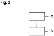
- Figure 2 shows a schematic sequence of a method for producing the battery pack device 10.
- the manufacturing materials are provided in a raw form.
- the wall 22 is formed curved.
- FIG. 3 shows a battery pack 50a with a battery pack device 10a.
- the battery pack device 10a has a battery pack housing 12a.
- the battery pack device 10a has at least one interface 14a for an electrical and mechanical connection to a consumer.
- the interface 14a is arranged on an interface side 18a of the battery pack housing 12a.
- the interface 14a has at least one contact receptacle 20a.
- the contact receptacle 20a is arranged adjacent to a wall 22a of the battery pack device 10a.
- the wall 22a is curved.
- the battery pack housing 12a has a first surface 24a on the interface side 18a and a second surface 26a that is recessed relative to the first surface 24a.
- the wall 22a is at least partially arranged in a region 30a of the second surface 26a.
- a further surface 68a is arranged between the first surface 24a and the second surface 26a.
- the further surface 68a connects the first surface 24a to the second surface 26a, in particular at least on the interface side 18a.
- the further surface 68a connects the first surface 24a to the second surface 26a in a ramp-like manner.
- the further surface 68a runs at an angle to the first surface 24a.
- the further surface 68a runs at an angle to the second surface 26a.
- the further surface 68a runs at least substantially perpendicular to the first surface 24a.
- the further surface 68a runs at least substantially perpendicular to the second surface 26a.
- the further surface 68a is arranged at least substantially completely between planes defined by the first surface 24a and the second surface 26a.
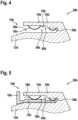
- the Figures 4 and 5 show a battery pack 50b with a battery pack device 10b.
- the battery pack device 10b has a battery pack housing 12b.
- the battery pack device 10b has at least one interface 14b for an electrical and mechanical connection to a consumer 16b.
- the interface 14b is arranged on an interface side 18b of the battery pack housing 12b.
- the interface 14b has two guide rails 34b (in the Figures 4 and 5 only one of the two guide rails 34b is shown in each case).
- the interface 14b has at least one flexible unit 36b.
- the flexible unit 36b is arranged at least partially on the guide rails 34b.
- the flexible unit 36b is provided to dampen shocks on the consumer and/or the battery pack device 10b, preferably the interface 14b and/or the battery pack housing 12b.
- the flexible unit 36b has several flexible, preferably elastic, elements 38b (in the Figures 4 and 5 only two of the several flexible elements 38b are shown).
- the flexible elements 38b are on a side 40b of the guide rails 34b facing the battery pack housing 12b Alternatively, it is conceivable that the flexible unit 36b has only one flexible element 38b.
- the flexible elements 38b are arranged on a surface 70b of the guide rails 34b opposite the battery pack housing 12b.
- the flexible elements 38b are arranged between the respective guide rail 34b and the battery pack housing 12b.
- the flexible elements 38b are arranged at a distance from the battery pack housing 12b.
- the flexible elements 38b are each fastened to one of the guide rails 34b.
- the flexible elements 38b can be deflected in the direction of the respective guide rail 34b, preferably elastically, preferably in order to dampen impacts on the respective guide rail 34b.
- the flexible elements 38b are formed in one piece with the respective guide rail 34b, or that the flexible elements 38b are fastened to the respective guide rail 34b in a detachable manner, in particular in a non-destructive manner. It is conceivable, for example, that the flexible elements 38b are attached to the respective guide rail 34b by overmolding, claw-locking, hot-stamping or the like.
- the flexible elements 34b rest on the consumer 16b, in particular on a battery pack interface 72b of the consumer 16b.
- the flexible elements 38b are prestressed. A prestress of the flexible elements 38b can be generated in particular by connecting the consumer 16b to the interface 14b.
- the flexible unit 36b has at least one flexible, preferably elastic, element 38b, which is arranged on a side facing away from the battery pack housing 12b on at least one of the guide rails 34b.
- the flexible unit 38b has at least one flexible, preferably elastic, element 38b, which is arranged on the battery pack housing 12b, preferably fastened, preferably on the interface side 18b.
- the flexible elements 38b are designed as leaf springs.
- the flexible elements 38b are designed as stamped and bent parts.
- the flexible elements 38b can be made of at least one metal, a plastic or the like.
- at least some of the flexible elements 38b are designed as rubber-elastic elements, for example as a rubber plate, as a rubber cube or the like, as a helical spring, as a leg spring or the like.
- FIG. 6 shows a battery pack 50c with a battery pack device 10c.
- the battery pack device 10c has a battery pack housing 12c.
- the battery pack device 10c has at least one interface 14c for an electrical and mechanical connection to a consumer.
- the interface 14c is arranged on an interface side 18c of the battery pack housing 12c.
- the interface 14c has two guide rails 34c.
- the interface 14c has at least one flexible unit 36c.
- the flexible unit 36c is arranged on the guide rails 34c.
- the flexible unit 36c has two flexible, preferably elastic, elements 42c (in Figure 6 only one of the two flexible elements 42c is shown). Alternatively, it is conceivable that the flexible unit 36c has only one flexible element 42c or more than two flexible elements 42c.
- the flexible elements 42c are each arranged between two mounting ribs 44c, 46c of the guide rail 34c that run at least substantially parallel to one another (in Figure 6 only the mounting ribs 44c, 46c of one of the two guide rails 34c are provided with reference symbols).
- the mounting ribs 44c, 46c each have guide surfaces along which the consumer can be guided during assembly on and/or disassembly from the battery pack device 10c.
- the mounting ribs 44c, 46c are arranged on opposite sides of the respective guide rail 34c.
- One mounting rib 44c of the mounting ribs 44c, 46c is arranged on a side of the respective guide rail 34c facing the battery pack housing 12c.
- Another mounting rib 46c of the mounting ribs 44c, 46c is arranged on a side of the respective guide rail 34c facing away from the battery pack housing 12c.
- the other mounting rib 46c is stronger than the mounting rib 44c.
- the mounting rib 44c and the further mounting rib 46c have the same thickness, or that the mounting rib 44c is stronger than the further mounting rib 46c.
- the mounting ribs 44c, 46c run at least substantially parallel to one another.
- the mounting ribs 44c, 46c run at least substantially parallel to an assembly direction and/or to the main extension axes of the guide rails 34c.
- the mounting ribs 44c, 46c run at an angle to one another.
- the mounting ribs 44c, 46c run at an angle to the assembly direction and/or to the main extension axes of the guide rails 34c.
- the flexible elements 42c each extend at least over a part of a maximum longitudinal extension of the respective guide rail 34c, in particular over at least 25%, preferably over at least 50% of the maximum longitudinal extension and preferably at least substantially over the entire maximum longitudinal extension of the respective guide rail 34c, in particular over at least 75% and particularly preferably over at least 90% of the maximum longitudinal extension of the respective guide rail 34c.
- the guide rails 34c each have a receiving chamber 48c for one of the flexible elements 42c (in Figure 6 only one of the receiving chambers 48c is shown).
- the receiving chambers 48c are open on one side in the assembled state.
- the receiving chambers 48c each extend at least over part of a maximum longitudinal extent of the respective guide rail 34c, in particular over at least 25%, preferably over at least 50% of the maximum longitudinal extent and preferably at least substantially over the entire maximum longitudinal extent of the respective guide rail 34c, in particular over at least 75% and particularly preferably over at least 90% of the maximum longitudinal extent of the respective guide rail 34c.
- the receiving chambers 48c are arranged between the mounting rib 44c and the further mounting rib 46c of the respective guide rail 34c.
- the guide rails 34c have several receiving chambers 48c for each flexible, in particular elastic, element 42c. Furthermore, it is conceivable that a plurality of flexible, in particular elastic, elements 42c can be arranged in the receiving chambers 48c.
- the flexible elements 42c are designed as flexible layer elements.
- the flexible elements 42c are each designed as an elastomer filling.
- the elastomer filling is made in particular from entropy-plastic material.
- the flexible elements 42c are at least essentially plate-shaped. Alternatively, however, it is also conceivable for the flexible elements 42c to have a different shape, in particular one that is different from an at least essentially plate-shaped shape, for example tubular, bar-shaped, prism-shaped, or the like.
- the flexible elements 42c fill the respective receiving chamber 48c at least essentially completely. It is conceivable for the flexible elements 42c to be clamped and/or glued in the respective receiving chamber 48c.
- An interface housing 60c of the interface 14c, in particular the guide rails 34c, are in particular at least partially, preferably at least essentially completely, formed from a hard plastic.
- the flexible elements 42c have a hardness that is lower than a hardness of the guide rails 34c.
- the flexible elements have a flexibility that is higher than a flexibility of the guide rails 34c.
- the flexible elements 34c have an elasticity that is higher than an elasticity of the guide rails 34c.
- the receiving chambers 48c are completely closed in the assembled state.
- the flexible elements 42c are at least partially or at least substantially completely molded around by the interface housing 60c of the interface 14c.
Landscapes
- Chemical & Material Sciences (AREA)
- Chemical Kinetics & Catalysis (AREA)
- Electrochemistry (AREA)
- General Chemical & Material Sciences (AREA)
- Engineering & Computer Science (AREA)
- Life Sciences & Earth Sciences (AREA)
- Biophysics (AREA)
- Computer Hardware Design (AREA)
- Manufacturing & Machinery (AREA)
- Battery Mounting, Suspending (AREA)
Abstract
Die Erfindung geht aus von einer Akkupackvorrichtung (10) mit zumindest einem Akkupackgehäuse (12) und mit zumindest einer Schnittstelle (14) zu einer elektrischen und mechanischen Verbindung mit einem Verbraucher, die auf einer Schnittstellenseite (18) des Akkupackgehäuses (12) angeordnet ist, wobei die Schnittstelle (14) zumindest eine Kontaktaufnahme (20) aufweist, die benachbart zu einer Wandung (22) der Akkupackvorrichtung (10) angeordnet ist.
Es wird vorgeschlagen, dass die Wandung (22) gekrümmt ausgebildet ist.
Description
- Es ist bereits eine Akkupackvorrichtung mit zumindest einem Akkupackgehäuse und mit zumindest einer Schnittstelle zu einer elektrischen und mechanischen Verbindung mit einem Verbraucher, die auf einer Schnittstellenseite des Akkupackgehäuses angeordnet ist, wobei die Schnittstelle zumindest eine Kontaktaufnahme aufweist, die benachbart zu einer Wandung angeordnet ist, vorgeschlagen worden.
- Die Erfindung geht aus von einer Akkupackvorrichtung mit zumindest einem Ackupackgehäuse und mit zumindest einer Schnittstelle zu einer elektrischen und mechanischen Verbindung mit einem Verbraucher, die auf einer Schnittstellenseite des Akkupackgehäuses angeordnet ist, wobei die Schnittstelle zumindest eine Kontaktaufnahme aufweist, die benachbart zu einer Wandung der Akkupackvorrichtung angeordnet ist.
- Es wird vorgeschlagen, dass die Wandung gekrümmt ausgebildet ist.
- Durch eine derartige Ausgestaltung der Akkupackvorrichtung kann eine besonders hohe Robustheit erreicht werden. Es kann eine besonders strapazierfähige und stabile Akkupackvorrichtung zur Verfügung gestellt werden. Vorteilhaft kann eine besonders hohe Sicherheit erreicht werden. Es kann vorteilhaft eine besonders hohe Produktqualität erreicht werden. Eine derartige Ausgestaltung der Akkupackvorrichtung ermöglicht eine Reduzierung von Spannungsspitzen und/oder eine Verbesserung eines Kraftflusses. Vorteilhaft kann einem durch Spannungsspitzen erzeugten Reißen der Akkupackvorrichtung und/oder der Schnittstelle besonders einfach und/oder effektiv entgegengewirkt werden.
- Die Schnittstelle ist insbesondere zumindest teilweise einstückig mit dem Akkupackgehäuse ausgebildet. Darunter, dass "zumindest eine Einheit oder ein Objekt und zumindest eine weitere Einheit oder ein weiteres Objekt zumindest teilweise einstückig miteinander ausgebildet sind" soll insbesondere verstanden werden, dass zumindest ein Element der Einheit oder des Objekts einstückig mit zumindest einem weiteren Element der weiteren Einheit oder dem weiteren Objekt ausgebildet ist. Unter "einstückig" kann zumindest stoffschlüssig verbunden verstanden werden, beispielsweise durch einen Schweißprozess, einen Lötprozess, einen Klebeprozess, einen Anspritzprozess und/oder einen anderen, dem Fachmann als sinnvoll erscheinenden Prozess, und/oder vorteilhaft in einem Stück geformt verstanden werden, wie beispielsweise durch eine Herstellung aus einem Guss und/oder durch eine Herstellung in einem Ein- oder Mehrkomponentenspritzverfahren und vorteilhaft aus einem einzelnen Rohling.
- Die Akkupackvorrichtung ist vorzugsweise Teil eines Akkupacks, insbesondere eines Handwerkzeugmaschinenakkupacks. Die Kontaktaufnahme weist beispielsweise ein elektrisches Kontaktelement oder mehrere elektrische Kontaktelemente auf. Der Akkupack, insbesondere die Akkupackvorrichtung, weist bevorzugt eine Akkuzelleneinheit auf. Die Akkuzelleneinheit weist vorzugsweise eine Akkuzelle oder mehrere, insbesondere miteinander geschaltete, Akkuzellen auf. Das zumindest eine elektrische Kontaktelement kann insbesondere als Kontaktstecker oder als Kontaktschwert ausgebildet sein.
- Das zumindest eine elektrische Kontaktelement ist insbesondere dazu vorgesehen, eine elektrische Verbindung zwischen der Akkuzelleneinheit und dem Verbraucher, insbesondere einer Akkupackschnittstelle des Verbrauchers, herzustellen. Unter "vorgesehen" soll speziell eingerichtet, speziell ausgelegt und/oder speziell ausgestattet verstanden werden. Darunter, dass ein Objekt zu einer bestimmten Funktion vorgesehen ist, soll verstanden werden, dass das Objekt diese bestimmte Funktion in zumindest einem Anwendungs- und/oder Betriebszustand erfüllt und/oder ausführt.
- Der Verbraucher ist bevorzugt als eine Handwerkzeugmaschine, beispielsweise als eine Bohrmaschine, als eine Schraubmaschine, als eine Sägemaschine, als eine Schleifmaschine oder als eine andere, einem Fachmann als sinnvoll erscheinende Handwerkzeugmaschine ausgebildet. Alternativ ist denkbar, dass der Verbraucher als ein Haushaltsgerät, beispielsweise als eine Küchenmaschine, als ein Reinigungsgerät, insbesondere als ein Staubsauger, als ein Radio, als eine Leuchte oder als ein anderes, einem Fachmann als sinnvoll erscheinendes Elektrogerät ausgebildet ist.
- Die Schnittstelle weist insbesondere eine mechanische Verbindungseinheit zu einer mechanischen Verbindung des Akkupacks, insbesondere der Akkupackvorrichtung, mit dem Verbraucher auf. Vorzugsweise ist mittels der mechanischen Verbindungseinheit die Akkupackvorrichtung, bevorzugt lösbar, besonders bevorzugt zerstörungsfrei lösbar, an dem Verbraucher befestigbar. Die mechanische Verbindungseinheit weist insbesondere zumindest eine Führungsschiene, bevorzugt zwei Führungsschienen, auf. Vorzugsweise ist der Verbraucher zu einer Montage und/oder Demontage des Verbrauchers an/von dem Akkupack, insbesondere der Akkupackvorrichtung, an der Führungsschiene entlangführbar. Die Führungsschiene ist insbesondere als Halteschiene für den Verbraucher vorgesehen.
- Die Schnittstellenseite ist insbesondere in einem an dem Verbraucher angeordneten Zustand des Akkupacks, vorzugsweise der Akkupackvorrichtung, dem Verbraucher zugewandt. Die Wandung ist bevorzugt einstückig mit zumindest einem Teil des Akkupackgehäuses und/oder zumindest einem Teil der Schnittstelle ausgebildet. Die Wandung ist insbesondere zwischen der Schnittstelle, insbesondere der Kontaktaufnahme, und dem Akkupackgehäuse angeordnet. Bevorzugt verbindet die Wandung das Akkupackgehäuse mit der Schnittstelle, insbesondere mit der Kontaktaufnahme, insbesondere zumindest in einem Teilbereich der Acku packvorrichtu ng.
- Die Schnittstelle weist insbesondere ein Schnittstellengehäuse auf. Das Schnittstellengehäuse ist zumindest teilweise einstückig mit dem Akkupackgehäuse und/oder der Wandung ausgebildet. Die Wandung schließt insbesondere an eine Außenfläche der Schnittstelle, vorzugsweise des Schnittstellengehäuses, an. Die Wandung schließt insbesondere an einer Außenfläche des Akkupackgehäuses an. Die Außenfläche des Akkupackgehäuses verläuft vorzugsweise winklig zu der Außenfläche des Schnittstellengehäuses. Unter "winklig" soll insbesondere in einem Winkel größer 0° und kleiner 180° verstanden werden. Vorzugsweise verläuft die Außenfläche des Akkupackgehäuses zumindest im Wesentlichen senkrecht zu der Außenfläche der Schnittstelle, insbesondere des Schnittstellengehäuses. Unter "im Wesentlichen senkrecht" kann eine Ausrichtung einer Richtung relativ zu einer Bezugsrichtung verstanden werden, wobei die Richtung und die Bezugsrichtung, insbesondere in einer Projektionsebene betrachtet, einen Winkel von 90° einschließen und der Winkel eine maximale Abweichung von insbesondere kleiner als 8°, vorteilhaft kleiner als 5° und besonders vorteilhaft kleiner als 2° aufweist.
- Die Wandung weist vorzugsweise eine konstante Krümmung auf. Alternativ ist denkbar, dass die Wandung eine variierende Krümmung aufweist. Die Wandung definiert vorzugsweise einen Kreisbogen mit einem Mittelpunktswinkel von zwischen 0° und 180°, bevorzugt 90°.
- Des Weiteren wird vorgeschlagen, dass das Akkupackgehäuse auf der Schnittstellenseite eine erste Oberfläche und eine gegenüber der ersten Oberfläche vertiefte zweite Oberfläche aufweist, wobei die Wandung zumindest teilweise in einem Bereich der zweiten Oberfläche angeordnet ist. Vorteilhaft kann eine besonders kompakte Akkupackvorrichtung zur Verfügung gestellt werden. Es kann ohne einen erhöhten Platzbedarf eine besonders robuste Akkupackvorrichtung realisiert werden. Unter "zumindest teilweise" kann zu zumindest 10 %, bevorzugt zu zumindest 25 % und besonders bevorzugt zu zumindest 40 % eines Gesamtvolumens und/oder einer Gesamtmasse eines Objekts, insbesondere der Wandung, verstanden werden. Bevorzugt ist die Wandung zumindest im Wesentlichen vollständig in dem Bereich der zweiten Oberfläche angeordnet, zumindest betrachtet in einer zu der zweiten Oberfläche senkrecht verlaufenden Richtung. Unter "zumindest im Wesentlichen vollständig" kann zu zumindest 50 %, bevorzugt zu zumindest 75 % und besonders bevorzugt zu zumindest 90 % eines Gesamtvolumens und/oder einer Gesamtmasse eines Objekts, insbesondere der Wandung, verstanden werden. Insbesondere ist die Wandung auf der zweiten Oberfläche angeordnet. Die erste Oberfläche ist vorzugsweise auf der Schnittstellenseite angeordnet. Die zweite Oberfläche ist vorzugsweise auf der Schnittstellenseite angeordnet. Die erste Oberfläche verläuft bevorzugt zumindest im Wesentlichen parallel zu der zweiten Oberfläche. Unter "im Wesentlichen parallel" kann hier eine Ausrichtung einer Richtung relativ zu einer Bezugsrichtung, insbesondere in einer Ebene, verstanden werden, wobei die Richtung gegenüber der Bezugsrichtung eine Abweichung insbesondere kleiner als 8°, vorteilhaft kleiner als 5° und besonders vorteilhaft kleiner als 2° aufweist. Alternativ ist jedoch auch denkbar, dass die erste Oberfläche winklig zu der zweiten Oberfläche verläuft. Ein Wert einer maximalen Höhe der Wandung entspricht vorzugsweise einem Wert eines minimalen Abstands der ersten Oberfläche zu der zweiten Oberfläche, insbesondere zumindest betrachtet in einer zu der ersten Oberfläche und/oder zweiten Oberfläche senkrecht verlaufenden Richtung. Alternativ ist denkbar, dass ein Wert der maximalen Höhe der Wandung kleiner oder größer ist als ein Wert des minimalen Abstands der ersten Oberfläche zu der zweiten Oberfläche, insbesondere zumindest betrachtet in der zu der ersten Oberfläche und/oder zweiten Oberfläche senkrecht verlaufenden Richtung. Die zweite Oberfläche ist insbesondere bezüglich der Schnittstelle gegenüber der ersten Oberfläche vertieft angeordnet. Die erste Oberfläche und die zweite Oberfläche definieren insbesondere jeweils eine Ebene, wobei die Wandung vorzugsweise zumindest teilweise, bevorzugt zumindest im Wesentlichen vollständig und besonders bevorzugt vollständig zwischen den Ebenen angeordnet ist. Die zweite Oberfläche entspricht vorzugsweise der zuvor bereits genannten Außenfläche des Akkupackgehäuses. Die Schnittstelle, insbesondere das Schnittstellengehäuse, ist vorzugsweise zumindest teilweise, bevorzugt zumindest im Wesentlichen vollständig auf der ersten Oberfläche angeordnet.
- Zudem wird vorgeschlagen, dass zumindest ein einer Montagerichtung der Schnittstelle zugewandter Teil der Wandung in dem Bereich der zweiten Oberfläche angeordnet ist. Vorteilhaft kann einer Beschädigung der Schnittstelle und/oder des Akkupackgehäuses, insbesondere in einem Übergangsbereich zwischen der Schnittstelle und dem Akkupackgehäuse, vorzugsweise bei einem Verbinden mit und/oder Lösen von dem Verbraucher, konstruktiv einfach und/oder effektiv entgegengewirkt werden. Vorteilhaft können Spannungsspitzen an besonders kritischen Stellen reduziert werden. Bevorzugt ist die Wandung zumindest im Wesentlichen vollständig auf einer der Montagerichtung zugewandten Seite der Schnittstelle angeordnet. Die Montagerichtung verläuft bevorzugt zumindest im Wesentlichen parallel zu der zumindest einen Führungsschiene, insbesondere einer Haupterstreckungsachse der zumindest einen Führungsschiene. Unter einer "Haupterstreckungsachse" eines Objekts kann dabei insbesondere eine Achse verstanden werden, welche parallel zu einer längsten Kante eines kleinsten geometrischen Quaders verläuft, welcher das Objekt gerade noch vollständig umschließt, und insbesondere durch den Mittelpunkt des Quaders verläuft. Die erste Oberfläche und/oder die zweite Oberfläche verlaufen/verläuft insbesondere zumindest im Wesentlichen parallel zu der Montagerichtung. Die Montagerichtung entspricht insbesondere einer Bewegungsrichtung des Verbrauchers relativ zu dem Akkupack, insbesondere der Akkupackvorrichtung bei einer Montage des Verbrauchers an dem Akkupack, vorzugsweise der Akkupackvorrichtung, bevorzugt der Schnittstelle. Insbesondere erfolgt bei einer Demontage des Verbrauchers von der Akkupackvorrichtung, vorzugsweise von dem Akkupack, eine Bewegung des Verbrauchers relativ zu der Akkupackvorrichtung, insbesondere zu dem Akkupack, entgegen der Montagerichtung. Eine Haupterstreckungsachse der Wandung verläuft bevorzugt zumindest im Wesentlichen senkrecht zu der Montagerichtung. Die Haupterstreckungsachse der Wandung verläuft insbesondere zumindest im Wesentlichen senkrecht zu der zumindest einen Führungsschiene, vorzugsweise der Haupterstreckungsachse der zumindest einen Führungsschiene.
- Weiterhin wird vorgeschlagen, dass der Bereich der zweiten Oberfläche zumindest auf einer einer, insbesondere der zuvor bereits genannten, Montagerichtung der Schnittstelle zugewandten Seite der Schnittstelle angeordnet ist. Vorteilhaft kann einer Beschädigung der Schnittstelle und/oder des Akkupackgehäuses, insbesondere in einem Übergangsbereich zwischen der Schnittstelle und dem Akkupackgehäuse, vorzugsweise bei einem Verbinden mit und/oder Lösen von dem Verbraucher, konstruktiv einfach, effektiv und/oder platzsparend entgegengewirkt werden. Vorteilhaft können Spannungsspitzen an besonders kritischen Stellen besonders platzsparend reduziert werden. Die erste Oberfläche ist insbesondere in einer zu der Montagerichtung parallel verlaufenden Richtung betrachtet der zweiten Oberfläche nachfolgend angeordnet.
- Ferner wird vorgeschlagen, dass die Schnittstelle zumindest eine, insbesondere die zuvor bereits genannte, Führungsschiene und zumindest eine flexible Einheit aufweist, die zumindest teilweise an der Führungsschiene angeordnet ist. Vorteilhaft kann eine besonders robuste Akkupackvorrichtung zur Verfügung gestellt werden. Es kann konstruktiv einfach und/oder besonders effektiv Beschädigungen des Akkupackgehäuses, der Schnittstelle und/oder dem Verbraucher durch Stöße oder dergleichen entgegengewirkt werden. Es kann eine besonders langlebige und/oder zuverlässige Akkupackvorrichtung zur Verfügung gestellt werden. Die flexible Einheit ist insbesondere dazu vorgesehen, Stöße auf den Verbraucher und/oder die Akkupackvorrichtung, vorzugsweise die Schnittstelle und/oder das Akkupackgehäuse, zu dämpfen. Die flexible Einheit kann beispielsweise ein flexibles, insbesondere elastisches, Element oder mehrere flexible, insbesondere elastische, Elemente aufweisen.
- Außerdem wird vorgeschlagen, dass die flexible Einheit zumindest ein, insbesondere das zuvor bereits genannte, flexible/s, vorzugsweise elastische/s, Element aufweist, welches auf einer dem Akkupackgehäuse zugewandten Seite der Führungsschiene angeordnet ist. Vorteilhaft kann eine besonders zuverlässige Fixierung der Akkupackvorrichtung an dem Verbraucher realisiert werden. Es kann eine besonders schonende und gleichzeitig präzise Fixierung der Akkupackvorrichtung an dem Verbraucher erreicht werden. Vorteilhaft kann eine besonders langlebige Akkupackvorrichtung realisiert werden. Das flexible Element ist bevorzugt auf einer dem Akkupackgehäuse gegenüberliegenden Oberfläche der Führungsschiene angeordnet. Vorzugsweise ist das flexible Element zwischen der Führungsschiene und dem Akkupackgehäuse angeordnet. Bevorzugt ist das flexible Element beabstandet zu dem Akkupackgehäuse angeordnet. Das flexible Element ist vorzugsweise an der Führungsschiene befestigt. Das flexible Element ist insbesondere in Richtung der Führungsschiene, vorzugsweise elastisch, auslenkbar, bevorzugt um Stöße auf die Führungsschiene abzudämpfen. Es ist denkbar, dass das flexible Element einstückig mit der Führungsschiene ausgebildet ist, oder dass das flexible Element lösbar, insbesondere zerstörungsfrei lösbar, an der Führungsschiene befestigt ist. Das elastische Element ist beispielsweise an zwei Stellen oder alternativ an lediglich einer Stelle der Führungsschiene befestigt. Es ist beispielsweise denkbar, dass das flexible Element durch Umspritzung, Verkrallen, Heißverstemmen oder dergleichen an der Führungsschiene befestigt ist. Das flexible Element liegt vorzugsweise in einem an dem Verbraucher angeordneten Zustand der Schnittstelle an dem Verbraucher, insbesondere an der Akkupackschnittstelle des Verbrauchers, an. Bevorzugt ist das flexible Element in einem an der Akkupackvorrichtung angeordneten Zustand des Verbrauchers vorgespannt. Eine Vorspannung des flexiblen Elements ist insbesondere durch eine Verbindung des Verbrauchers mit der Schnittstelle erzeugbar. Alternativ oder zusätzlich ist auch denkbar, dass die flexible Einheit zumindest ein, insbesondere das zuvor bereits genannte, flexible/s, vorzugsweise elastische/s, Element aufweist, welches auf einer dem Akkupackgehäuse abgewandten Seite der Führungsschiene angeordnet ist. Ferner ist alternativ oder zusätzlich denkbar, dass die flexible Einheit zumindest ein, insbesondere das zuvor bereits genannte, flexible/s, vorzugsweise elastische/s, Element aufweist, welches an dem Akkupackgehäuse angeordnet, vorzugsweise befestigt, ist, bevorzugt auf der Schnittstellenseite.
- Des Weiteren wird vorgeschlagen, dass das flexible Element als eine Blattfeder ausgebildet ist. Vorteilhaft kann eine besonders zuverlässige und/oder präzise Fixierung des Verbrauchers an der Akkupackvorrichtung, insbesondere an der Schnittstelle, kostengünstig realisiert werden. Das elastische Element ist bevorzugt als Stanzbiegeteil ausgebildet. Das elastische Element kann beispielsweise aus einem Metall, aus einem Kunststoff oder dergleichen ausgebildet sein. Alternativ ist auch denkbar, dass das flexible Element als ein gummielastisches Element, beispielsweise als eine Gummiplatte, als ein Gummiwürfel oder dergleichen, als eine Schraubenfeder, als eine Schenkelfeder oder dergleichen ausgebildet ist.
- Zudem wird vorgeschlagen, dass die flexible Einheit zumindest, insbesondere das zuvor bereits genannte, ein flexible/s, vorzugsweise elastische/s Element, aufweist, welches zwischen zwei zueinander zumindest im Wesentlichen parallel verlaufenden Montagerippen der Führungsschiene angeordnet ist. Vorteilhaft kann eine besonders platzsparende flexible Einheit zur Verfügung gestellt werden. Vorteilhaft kann eine kompakte und gleichzeitig besonders robuste und/oder langlebige Akkupackvorrichtung bereitgestellt werden. Die Montagerippen weisen insbesondere jeweils eine Führungsfläche auf, entlang derer der Verbraucher bei einer Montage an und/oder einer Demontage von der Akkupackvorrichtung, vorzugsweise der Schnittstelle, führbar ist. Die Montagerippen sind vorzugsweise auf zueinander abgewandten Seiten der Führungsschiene angeordnet. Eine Montagerippe der Montagerippen ist insbesondere auf einer zu dem Akkupackgehäuse zugewandten Seite der Führungsschiene angeordnet. Eine weitere Montagerippe der Montagerippen ist insbesondere auf einer zu dem Akkupackgehäuse abgewandten Seite der Führungsschiene angeordnet. Die weitere Montagerippe ist vorzugsweise stärker ausgebildet als die Montagerippe. Alternativ ist denkbar, dass die Montagerippe und die weitere Montagerippe die gleiche Stärke aufweisen, oder dass die Montagerippe stärker ausgebildet ist als die weitere Montagerippe. Die Montagerippen verlaufen bevorzugt zumindest im Wesentlichen parallel zueinander. Die Montagerippen verlaufen vorzugsweise zumindest im Wesentlichen parallel zu der Montagerichtung und/oder zu der Haupterstreckungsachse der Führungsschiene. Alternativ ist denkbar, dass die Montagerippen winklig zueinander verlaufen. Alternativ ist auch denkbar, dass die Montagerippen, insbesondere die Montagerippe und/oder die weitere Montagerippe, winklig zu der Montagerichtung und/oder zu der Haupterstreckungsachse der Führungsschiene verlaufen. Das flexible Element erstreckt sich vorzugsweise zumindest über einen Teil einer maximalen Längserstreckung der Führungsschiene, insbesondere über zumindest 25 %, vorzugsweise über zumindest 50 % der maximalen Längserstreckung und bevorzugt zumindest im Wesentlichen über die gesamte maximale Längserstreckung der Führungsschiene, insbesondere über zumindest 75 % und besonders bevorzugt über zumindest 90 % der maximalen Längserstreckung der Führungsschiene.
- Weiterhin wird vorgeschlagen, dass die zumindest eine Führungsschiene eine Aufnahmekammer für ein, insbesondere das zuvor bereits genannte, flexible/s, insbesondere elastische/s, Element aufweist, wobei die Aufnahmekammer im montierten Zustand vollständig geschlossen oder einseitig offen ausgebildet ist. Vorteilhaft kann eine besonders platzsparende flexible Einheit zur Verfügung gestellt werden. Vorteilhaft kann eine kompakte und gleichzeitig besonders robuste und/oder langlebige Akkupackvorrichtung bereitgestellt werden. Das flexible Element ist, insbesondere in zumindest einem Ausführungsbeispiel, als ein flexibles Schichtelement ausgebildet. Das flexible Element ist beispielsweise plattenförmig ausgebildet. Darunter, dass ein Objekt "zumindest im Wesentlichen plattenförmig" ausgestaltet ist, soll insbesondere verstanden werden, dass zumindest ein kleinstmöglicher geometrischer Quader, welcher das Objekt gerade noch vollständig umschließt, plattenförmig ist. Darunter, dass ein Objekt "plattenförmig" ausgestaltet ist, soll insbesondere ein räumliches Objekt verstanden werden, das, in einer Abwicklung in einer Ebene betrachtet, in einem Querschnitt senkrecht zur Ebene eine unrunde Querschnittsfläche aufweist und senkrecht zur Ebene eine insbesondere zumindest im Wesentlichen gleichbleibende Materialstärke aufweist, die weniger als 50 %, vorzugsweise weniger als 25 % und besonders bevorzugt weniger als 10 % einer Flächenerstreckung des räumlichen Elements parallel zur Ebene, insbesondere einer kleinsten Flächenerstreckung des Elements parallel zur Ebene, beträgt. Alternativ ist jedoch auch denkbar, dass das flexible Element eine andere, insbesondere von einer zumindest im Wesentlichen plattenförmigen Form verschiedene, Form aufweist, beispielsweise rohrförmig, balkenförmig, prismenförmig, oder dergleichen. Vorzugsweise füllt das flexible Element die Aufnahmekammer zumindest im Wesentlichen vollständig aus. Es ist denkbar, dass das flexible Element in der Aufnahmekammer verklemmt und/oder verklebt ist. Es ist auch denkbar, dass das flexible Element zumindest teilweise oder zumindest im Wesentlichen vollständig von dem Schnittstellengehäuse umspritzt ist. Das Schnittstellengehäuse, insbesondere die Führungsschiene, ist vorzugsweise, insbesondere zumindest teilweise, bevorzugt zumindest im Wesentlichen vollständig, aus einem Hartplastik, beispielsweise aus einem glasfasergefüllten Thermoplast, insbesondere einem Polyamid mit Glasfaserfüllung, einem Polycarbonat, einem Copolymer, einem Gemisch aus einem Polycarbonat und einem Acrylnitril-Butadien-Styrol-Copolymer oder dergleichen, gebildet. Das flexible Element weist besonders bevorzugt eine Härte auf, die geringer ist als eine Härte der Führungsschiene. Das flexible Element weist bevorzugt eine Flexibilität auf, die höher ist als eine Flexibilität der Führungsschiene. Das flexible Element weist bevorzugt einen Shore A - Messwert von größer 60 und vorzugsweise kleiner 90 auf. Alternativ ist jedoch auch denkbar, dass der Shore A - Messwert kleiner 60 oder größer 90 ist. Das flexible Element weist besonders bevorzugt eine Elastizität auf, die höher ist als eine Elastizität der Führungsschiene. Eine Bruchdehnung des flexiblen Elements beträgt vorzugsweise zumindest 100%. Die Aufnahmekammer erstreckt sich vorzugsweise zumindest über einen Teil einer maximalen Längserstreckung der Führungsschiene, insbesondere über zumindest 25 %, vorzugsweise über zumindest 50 % der maximalen Längserstreckung und bevorzugt zumindest im Wesentlichen über die gesamte maximale Längserstreckung der Führungsschiene, insbesondere über zumindest 75 % und besonders bevorzugt über zumindest 90 % der maximalen Längserstreckung der Führungsschiene. Die Aufnahmekammer ist insbesondere zwischen der Montagerippe und der weiteren Montagerippe angeordnet. Es ist auch denkbar, dass die zumindest eine Führungsschiene mehrere Aufnahmekammern für jeweils ein flexibles, insbesondere elastisches, Element aufweist. Ferner ist denkbar, dass in der Aufnahmekammer mehrere flexible, insbesondere elastische, Elemente anordenbar sind.
- Ferner wird vorgeschlagen, dass das flexible, insbesondere elastische, Element als eine Elastomerfüllung ausgebildet ist, wobei die Elastomerfüllung insbesondere aus entropieplastischen Material ausgebildet ist. Vorteilhaft kann eine besonders einfache und/oder kostengünstige Herstellung der flexiblen Einheit erreicht werden.
- Außerdem wird ein, insbesondere der zuvor bereits genannte, Akkupack mit der Akkupackvorrichtung vorgeschlagen. Vorteilhaft kann ein besonders robuster und/oder langlebiger Akkupack zur Verfügung gestellt werden.
- Des Weiteren geht die Erfindung aus von einem Verfahren zur Herstellung einer Akkupackvorrichtung, insbesondere der zuvor bereits genannten, Akkupackvorrichtung mit einem, insbesondere dem zuvor bereits genannten, Akkupackgehäuse und mit zumindest einer, insbesondere der zuvor bereits genannten, Schnittstelle zu einer elektrischen und mechanischen Verbindung mit einem, insbesondere dem zuvor bereits genannten, Verbraucher, wobei die Schnittstelle zumindest eine, insbesondere die zuvor bereits genannte, Kontaktaufnahme aufweist, die benachbart zu einer, insbesondere der zuvor bereits genannten, Wandung der Akkupackvorrichtung angeordnet ist. Es wird vorgeschlagen, dass die Wandung zumindest teilweise gekrümmt ausgebildet wird. Durch eine derartige Ausgestaltung des Verfahrens kann eine besonders hohe Robustheit der Akkupackvorrichtung erreicht werden. Es kann ein besonders strapazierfähige und stabile Akkupackvorrichtung zur Verfügung gestellt werden. Vorteilhaft kann eine besonders hohe Sicherheit erreicht werden. Es kann vorteilhaft eine besonders hohe Produktqualität erreicht werden. Eine derartige Ausgestaltung der Akkupackvorrichtung ermöglicht eine Reduzierung von Spannungsspitzen und/oder eine Verbesserung eines Kraftflusses. Vorteilhaft kann einem durch Spannungsspitzen erzeugten Reißen der Akkupackvorrichtung und/oder der Schnittstelle besonders einfach und/oder effektiv entgegengewirkt werden.
- Die Akkupackvorrichtung, der Akkupack und/oder das Verfahren sollen/soll hierbei nicht auf die oben beschriebene Anwendung und Ausführungsform beschränkt sein. Insbesondere können/kann die Akkupackvorrichtung, der Akkupack und/oder das Verfahren zu einer Erfüllung einer hierin beschriebenen Funktionsweise eine von einer hierin genannten Anzahl von einzelnen Elementen, Bauteilen und Einheiten sowie Verfahrensschritten abweichende Anzahl aufweisen. Zudem sollen bei den in dieser Offenbarung angegebenen Wertebereichen auch innerhalb der genannten Grenzen liegende Werte als offenbart und als beliebig einsetzbar gelten.
- Weitere Vorteile ergeben sich aus der folgenden Zeichnungsbeschreibung. In der Zeichnung sind vier Ausführungsbeispiele der Erfindung dargestellt. Die Zeichnung, die Beschreibung und die Ansprüche enthalten zahlreiche Merkmale in Kombination. Der Fachmann wird die Merkmale zweckmäßigerweise auch einzeln betrachten und zu sinnvollen weiteren Kombinationen zusammenfassen.
- Es zeigen:
- Fig. 1
- einen Akkupack mit einer Akkupackvorrichtung in einer schematischen Darstellung,
- Fig. 2
- einen schematischen Ablauf eines Verfahrens zur Herstellung der Akkupackvorrichtung,
- Fig. 3
- einen Akkupack mit einer Akkupackvorrichtung in einer ersten alternativen Ausführung in einer schematischen Darstellung,
- Fig. 4
- einen Akkupack mit einer Akkupackvorrichtung in einer zweiten alternativen Ausführung in einer Querschnittsdarstellung,
- Fig. 5
- die Akkupackvorrichtung aus
Figur 4 in Verbindung mit einem Verbraucher in einer Querschnittsdarstellung und - Fig. 6
- einen Akkupack mit einer Akkupackvorrichtung in einer dritten alternativen Ausführung einer schematischen Darstellung.
-
Figur 1 zeigt einen Akkupack 50 mit einer Akkupackvorrichtung 10. Der Akkupack 50 ist hier beispielhaft als ein Handwerkzeugmaschinenakkupack ausgebildet. Die Akkupackvorrichtung 10 weist ein Akkupackgehäuse 12 auf. Die Akkupackvorrichtung 10 weist zumindest eine Schnittstelle 14 zu einer elektrischen und mechanischen Verbindung mit einem Verbraucher auf. Die Schnittstelle 14 ist insbesondere zumindest teilweise einstückig mit dem Akkupackgehäuse 12 ausgebildet. - Die Schnittstelle 14 ist auf einer Schnittstellenseite 18 des Akkupackgehäuses 12 angeordnet. Die Schnittstelle 14 weist zumindest eine Kontaktaufnahme 20 auf. Die Kontaktaufnahme 20 weist mehrere elektrische Kontaktelemente 56 auf. Alternativ ist denkbar, dass die Kontaktaufnahme 20 lediglich ein elektrisches Kontaktelement 56 aufweist. Der Akkupack 50, insbesondere die Akkupackvorrichtung 10, weist eine Akkuzelleneinheit (hier nicht dargestellt) auf. Die Akkuzelleneinheit weist eine Akkuzelle oder mehrere, insbesondere miteinander geschaltete, Akkuzellen auf. Die elektrischen Kontaktelemente 56 sind als Kontaktstecker ausgebildet. Alternativ ist denkbar, dass zumindest ein Teil der elektrischen Kontaktelemente 56 als Kontaktschwerter oder dergleichen ausgebildet sind. Die elektrischen Kontaktelemente 56 sind dazu vorgesehen, eine elektrische Verbindung der Akkuzelleneinheit und dem Verbraucher, insbesondere einer Akkupackschnittstelle des Verbrauchers, herzustellen.
- Der Verbraucher ist bevorzugt als eine Handwerkzeugmaschine, beispielsweise als eine Bohrmaschine, als eine Schraubmaschine, als eine Sägemaschine, als eine Schleifmaschine oder als eine andere, einem Fachmann als sinnvoll erscheinende Handwerkzeugmaschine ausgebildet. Alternativ ist denkbar, dass der Verbraucher als ein Haushaltsgerät, beispielsweise als eine Küchenmaschine, als ein Reinigungsgerät, insbesondere als ein Staubsauger, als ein Radio, als eine Leuchte oder als ein anderes, einem Fachmann als sinnvoll erscheinendes Elektrogerät ausgebildet ist.
- Die Schnittstelle 14 weist eine mechanische Verbindungseinheit 58 zu einer mechanischen Verbindung des Akkupacks 50, insbesondere der Akkupackvorrichtung 10, mit dem Verbraucher auf. Mittels der mechanischen Verbindungseinheit 58 ist die Akkupackvorrichtung 10, bevorzugt lösbar, besonders bevorzugt zerstörungsfrei lösbar, an dem Verbraucher befestigbar. Die mechanische Verbindungseinheit 58 weist zwei Führungsschienen 34 auf. Der Verbraucher ist zu einer Montage und/oder Demontage des Verbrauchers an/von dem Akkupack 50, insbesondere der Akkupackvorrichtung 10, an den Führungsschienen 34 entlangführbar. Die Führungsschienen 34 sind als Halteschienen für den Verbraucher vorgesehen. Die Schnittstellenseite 14 ist in einem an dem Verbraucher angeordneten Zustand des Akkupacks 50, vorzugsweise der Akkupackvorrichtung 10, dem Verbraucher zugewandt.
- Die Kontaktaufnahme 20 ist benachbart zu einer Wandung 22 der Akkupackvorrichtung 10 angeordnet. Die Wandung 22 ist einstückig mit zumindest einem Teil des Akkupackgehäuses 12 ausgebildet. Die Wandung 22 ist einstückig mit zumindest einem Teil der Schnittstelle 14 ausgebildet. Die Wandung 22 ist zwischen der Schnittstelle 14, insbesondere der Kontaktaufnahme 20, und dem Ackupackgehäuse 12 angeordnet. Die Wandung 22 verbindet das Akkupackgehäuse 12 mit der Schnittstelle 14, insbesondere mit der Kontaktaufnahme 20, insbesondere zumindest in einem Teilbereich der Akkupackvorrichtung 10.
- Die Wandung 22 ist gekrümmt ausgebildet. Die Wandung 22 weist eine konstante Krümmung auf. Alternativ ist denkbar, dass die Wandung 22 eine variierende Krümmung aufweist. Die Wandung 22 definiert einen Kreisbogen mit einem Mittelpunktswinkel von zwischen 0° und 180°, bevorzugt 90°.
- Die Schnittstelle 14 weist ein Schnittstellengehäuse 60 auf. Das Schnittstellengehäuse 60 ist zumindest teilweise einstückig mit dem Akkupackgehäuse 12 und/oder der Wandung 22 ausgebildet. Die Wandung 22 schließt an eine Außenfläche 62 der Schnittstelle 14, vorzugsweise des Schnittstellengehäuses 60, an. Die Wandung 20 schließt an eine Außenfläche 64 des Akkupackgehäuses 12 an. Die Außenfläche 64 des Akkupackgehäuses 12 verläuft winklig zu der Außenfläche 62 des Schnittstellengehäuses 60. Die Außenfläche 64 des Akkupackgehäuses 12 verläuft insbesondere zumindest im Wesentlichen senkrecht zu der Außenfläche 64 der Schnittstelle 14, vorzugsweise des Schnittstellengehäuses 60.
- Das Akkupackgehäuse 12 weist auf der Schnittstellenseite 18 eine erste Oberfläche 24 und eine gegenüber der ersten Oberfläche 24 vertiefte zweite Oberfläche 26 auf. Die Wandung 22 ist zumindest teilweise in einem Bereich 30 der zweiten Oberfläche 26 angeordnet. Die Wandung 22 ist zumindest im Wesentlichen vollständig in dem Bereich 30 der zweiten Oberfläche 26 angeordnet, zumindest betrachtet in einer zu der zweiten Oberfläche 26 senkrecht verlaufenden Richtung. Die Wandung 22 ist auf der zweiten Oberfläche 26 angeordnet. Die erste Oberfläche 24 ist auf der Schnittstellenseite 18 angeordnet. Die zweite Oberfläche 26 ist auf der Schnittstellenseite 18 angeordnet. Die erste Oberfläche 24 verläuft zumindest im Wesentlichen parallel zu der zweiten Oberfläche 26. Alternativ ist jedoch auch denkbar, dass die erste Oberfläche 24 winklig zu der zweiten Oberfläche 26 verläuft.
- Ein Wert einer maximalen Höhe der Wandung 22 entspricht einem Wert eines minimalen Abstands der ersten Oberfläche 24 zu der zweiten Oberfläche 26, insbesondere zumindest betrachtet in einer zu der ersten Oberfläche 24 und/oder zweiten Oberfläche 26 senkrecht verlaufenden Richtung. Alternativ ist denkbar, dass ein Wert der maximalen Höhe der Wandung 22 kleiner oder größer ist als ein Wert des minimalen Abstands der ersten Oberfläche 24 zu der zweiten Oberfläche 26, insbesondere zumindest betrachtet in der zu der ersten Oberfläche 24 und/oder zweiten Oberfläche 26 senkrecht verlaufenden Richtung. Die zweite Oberfläche 26 ist bezüglich der Schnittstelle 14 gegenüber der ersten Oberfläche 24 vertieft angeordnet. Die erste Oberfläche 24 und die zweite Oberfläche 26 definieren jeweils eine Ebene, wobei die Wandung 22 vollständig zwischen den Ebenen angeordnet ist. Alternativ ist denkbar, dass die Wandung 22 zumindest teilweise zwischen den durch die erste Oberfläche 24 und die zweite Oberfläche 26 definierten Ebenen angeordnet ist. Die zweite Oberfläche 26 entspricht der zuvor bereits genannten Außenfläche 64 des Akkupackgehäuses 12. Die Schnittstelle 14, insbesondere das Schnittstellengehäuse 60, ist zumindest teilweise, bevorzugt zumindest im Wesentlichen vollständig auf der ersten Oberfläche 24 angeordnet.
- Zumindest ein einer Montagerichtung 28 der Schnittstelle 14 zugewandter Teil der Wandung 22 ist in dem Bereich 30 der zweiten Oberfläche 26 angeordnet. Die Wandung 22 ist zumindest im Wesentlichen vollständig auf einer der Montagerichtung 28 zugewandten Seite der Schnittstelle 14 angeordnet. Die Montagerichtung 28 verläuft zumindest im Wesentlichen parallel zu den Führungsschienen 34, insbesondere jeweiligen Haupterstreckungsachsen 66 der Führungsschienen 34. Die erste Oberfläche 24 und/oder die zweite Oberfläche 26 verlaufen/verläuft zumindest im Wesentlichen parallel zu der Montagerichtung 28. Die Montagerichtung 28 entspricht einer Bewegungsrichtung des Verbrauchers relativ zu dem Akkupack 50, insbesondere der Akkupackvorrichtung 10 bei einer Montage des Verbrauchers an dem Akkupack 50, vorzugsweise der Akkupackvorrichtung 10, insbesondere der Schnittstelle 14.
- Eine Haupterstreckungsachse 74 der Wandung 22 verläuft zumindest im Wesentlichen senkrecht zu der Montagerichtung 28. Die Haupterstreckungsachse 74 der Wandung 22 verläuft zumindest im Wesentlichen senkrecht zu den Führungsschienen 34, vorzugsweise den Haupterstreckungsachsen 66 der Führungsschienen 34.
- Der Bereich 30 der zweiten Oberfläche 26 ist zumindest auf einer der Montagerichtung 28 der Schnittstelle 14 zugewandten Seite 32 der Schnittstelle 14 angeordnet. Die erste Oberfläche 24 ist in einer zu der Montagerichtung 28 parallel verlaufenden Richtung betrachtet der zweiten Oberfläche 26 nachfolgend angeordnet.
- Zwischen der ersten Oberfläche 24 und der zweiten Oberfläche 26 ist eine weitere Oberfläche 68 angeordnet. Die weitere Oberfläche 68 verbindet die erste Oberfläche 24 mit der zweiten Oberfläche, insbesondere zumindest auf der Schnittstellenseite 18. Die weitere Oberfläche 68 verbindet die erste Oberfläche 24 mit der zweiten Oberfläche 26 rampenartig. Die weitere Oberfläche 68 verläuft winklig zu der ersten Oberfläche 24. Die weitere Oberfläche 68 verläuft winklig zu der zweiten Oberfläche 26. Die weitere Oberfläche 68 verläuft zu der ersten Oberfläche 24 in einem Winkel verschieden von 90°. Die weitere Oberfläche 68 verläuft zu der zweiten Oberfläche 26 in einem Winkel verschieden von 90°. Die weitere Oberfläche 68 ist zumindest im Wesentlichen vollständig zwischen den durch die erste Oberfläche 24 und die zweite Oberfläche 26 definierenden Ebenen angeordnet.
-
Figur 2 zeigt einen schematischen Ablauf eines Verfahrens zur Herstellung der Akkupackvorrichtung 10. In einem Verfahrensschritt 52 werden die Herstellungsmaterialien in einer Rohform bereitgestellt. In einem Verfahrensschritt, insbesondere in einem Herstellungsschritt 54, wird die Wandung 22 gekrümmt ausgebildet. - In den
Figuren 3 bis 6 sind weitere Ausführungsbeispiele der Erfindung gezeigt. Die nachfolgenden Beschreibungen und die Zeichnungen beschränken sich im Wesentlichen auf die Unterschiede zwischen den Ausführungsbeispielen, wobei bezüglich gleich bezeichneter Bauteile, insbesondere in Bezug auf Bauteile mit gleichen Bezugszeichen, grundsätzlich auch auf die Zeichnungen und/oder die Beschreibung der anderen Ausführungsbeispiele, insbesondere derFiguren 1 und2 , verwiesen werden kann. Zur Unterscheidung der Ausführungsbeispiele ist den Bezugszeichen des Ausführungsbeispiels in denFiguren 1 und2 kein Buchstabe und der Ausführungsbeispiele in denFiguren 3 bis 6 die Buchstaben a bis c nachgestellt. -
Figur 3 zeigt einen Akkupack 50a mit einer Akkupackvorrichtung 10a. Die Akkupackvorrichtung 10a weist ein Akkupackgehäuse 12a auf. Die Akkupackvorrichtung 10a weist zumindest eine Schnittstelle 14a zu einer elektrischen und mechanischen Verbindung mit einem Verbraucher auf. Die Schnittstelle 14a ist auf einer Schnittstellenseite 18a des Akkupackgehäuses 12a angeordnet. Die Schnittstelle 14a weist zumindest eine Kontaktaufnahme 20a auf. Die Kontaktaufnahme 20a ist benachbart zu einer Wandung 22a der Akkupackvorrichtung 10a angeordnet. Die Wandung 22a ist gekrümmt ausgebildet. Das Akkupackgehäuse 12a weist auf der Schnittstellenseite 18a eine erste Oberfläche 24a und eine gegenüber der ersten Oberfläche 24a vertiefte zweite Oberfläche 26a auf. Die Wandung 22a ist zumindest teilweise in einem Bereich 30a der zweiten Oberfläche 26a angeordnet. - Zwischen der ersten Oberfläche 24a und der zweiten Oberfläche 26a ist eine weitere Oberfläche 68a angeordnet. Die weitere Oberfläche 68a verbindet die erste Oberfläche 24a mit der zweiten Oberfläche 26a, insbesondere zumindest auf der Schnittstellenseite 18a. Die weitere Oberfläche 68a verbindet die erste Oberfläche 24a mit der zweiten Oberfläche 26a rampenartig. Die weitere Oberfläche 68a verläuft winklig zu der ersten Oberfläche 24a. Die weitere Oberfläche 68a verläuft winklig zu der zweiten Oberfläche 26a. Die weitere Oberfläche 68a verläuft zumindest im Wesentlichen senkrecht zu der ersten Oberfläche 24a. Die weitere Oberfläche 68a verläuft zumindest im Wesentlichen senkrecht zu der zweiten Oberfläche 26a. Die weitere Oberfläche 68a ist zumindest im Wesentlichen vollständig zwischen durch die erste Oberfläche 24a und die zweite Oberfläche 26a definierenden Ebenen angeordnet.
- Die
Figuren 4 und 5 zeigen einen Akkupack 50b mit einer Akkupackvorrichtung 10b. Die Akkupackvorrichtung 10b weist ein Akkupackgehäuse 12b auf. Die Ackupackvorrichtung 10b weist zumindest eine Schnittstelle 14b zu einer elektrischen und mechanischen Verbindung mit einem Verbraucher 16b auf. Die Schnittstelle 14b ist auf einer Schnittstellenseite 18b des Akkupackgehäuses 12b angeordnet. - Die Schnittstelle 14b weist zwei Führungsschienen 34b (in den
Figuren 4 und 5 ist jeweils nur eine der zwei Führungsschienen 34b dargestellt) auf. Die Schnittstelle 14b weist zumindest eine flexible Einheit 36b auf. Die flexible Einheit 36b ist zumindest teilweise an den Führungsschienen 34b angeordnet. Die flexible Einheit 36b ist dazu vorgesehen, Stöße auf den Verbraucher und/oder die Akkupackvorrichtung 10b, vorzugsweise die Schnittstelle 14b und/oder das Akkupackgehäuse 12b, zu dämpfen. - Die flexible Einheit 36b weist mehrere flexible, vorzugsweise elastische, Elemente 38b auf (in den
Figuren 4 und 5 sind lediglich zwei der mehreren flexiblen Elemente 38b dargestellt). Die flexiblen Elemente 38b sind auf einer dem Akkupackgehäuse 12b zugewandten Seite 40b der Führungsschienen 34b angeordnet. Alternativ ist denkbar, dass die flexible Einheit 36b lediglich ein flexibles Element 38b aufweist. - Die flexiblen Elemente 38b sind auf einer dem Akkupackgehäuse 12b gegenüberliegenden Oberfläche 70b der Führungsschienen 34b angeordnet. Die flexiblen Elemente 38b sind zwischen der jeweiligen Führungsschiene 34b und dem Akkupackgehäuse 12b angeordnet. Die flexiblen Elemente 38b sind beabstandet zu dem Akkupackgehäuse 12b angeordnet. Die flexiblen Elemente 38b sind jeweils an einer der Führungsschienen 34b befestigt. Die flexiblen Elemente 38b sind in Richtung der jeweiligen Führungsschiene 34b, vorzugsweise elastisch, auslenkbar, bevorzugt um Stöße auf die jeweilige Führungsschiene 34b abzudämpfen. Es ist denkbar, dass die flexiblen Elemente 38b einstückig mit der jeweiligen Führungsschiene 34b ausgebildet sind, oder dass die flexiblen Elemente 38b lösbar, insbesondere zerstörungsfrei lösbar, an der jeweiligen Führungsschiene 34b befestigt sind. Es ist beispielsweise denkbar, dass die flexiblen Elemente 38b durch Umspritzung, Verkrallen, Heißverstemmen oder dergleichen an der jeweiligen Führungsschiene 34b befestigt sind. Die flexiblen Elemente 34b liegen in einem an dem Verbraucher angeordneten Zustand der Schnittstelle 14b an dem Verbraucher 16b, insbesondere an einer Akkupackschnittstelle 72b des Verbrauchers 16b, an. Die flexiblen Elemente 38b sind in einem an der Akkupackvorrichtung 10b angeordneten Zustand des Verbrauchers 16b vorgespannt. Eine Vorspannung der flexiblen Elemente 38b ist insbesondere durch eine Verbindung des Verbrauchers 16b mit der Schnittstelle 14b erzeugbar.
- Alternativ oder zusätzlich ist auch denkbar, dass die flexible Einheit 36b zumindest ein flexibles, vorzugsweise elastisches, Element 38b aufweist, welches auf einer dem Akkupackgehäuse 12b abgewandten Seite auf zumindest einer der Führungsschienen 34b angeordnet ist. Ferner ist alternativ oder zusätzlich denkbar, dass die flexible Einheit 38b zumindest ein flexibles, vorzugsweise elastisches, Element 38b aufweist, welches an dem Akkupackgehäuse 12b angeordnet, vorzugsweise befestigt ist, bevorzugt auf der Schnittstellenseite 18b.
- Die flexiblen Elemente 38b sind als Blattfedern ausgebildet. Die flexiblen Elemente 38b sind als Stanzbiegeteile ausgebildet. Die flexiblen Elemente 38b können aus zumindest einem Metall, aus einem Kunststoff oder dergleichen ausgebildet sein. Alternativ ist auch denkbar, dass zumindest ein Teil der flexiblen Elemente 38b als gummielastische Elemente, beispielsweise als eine Gummiplatte, als ein Gummiwürfel oder dergleichen, als eine Schraubenfeder, als eine Schenkelfeder oder dergleichen ausgebildet sind.
-
Figur 6 zeigt einen Akkupack 50c mit einer Akkupackvorrichtung 10c. Die Akkupackvorrichtung 10c weist ein Akkupackgehäuse 12c auf. Die Akkupackvorrichtung 10c weist zumindest eine Schnittstelle 14c zu einer elektrischen und mechanischen Verbindung mit einem Verbraucher auf. Die Schnittstelle 14c ist auf einer Schnittstellenseite 18c des Akkupackgehäuses 12c angeordnet. - Die Schnittstelle 14c weist zwei Führungsschienen 34c auf. Die Schnittstelle 14c weist zumindest eine flexible Einheit 36c auf. Die flexible Einheit 36c ist an den Führungsschienen 34c angeordnet. Die flexible Einheit 36c weist zwei flexible, vorzugsweise elastische, Elemente 42c, auf (in
Figur 6 ist lediglich eines der zwei flexiblen Elemente 42c dargestellt). Alternativ ist denkbar, dass die flexible Einheit 36c lediglich ein flexibles Element 42c oder mehr als zwei flexible Elemente 42c aufweist. Die flexiblen Elemente 42c sind jeweils zwischen zwei zueinander zumindest im Wesentlichen parallel verlaufenden Montagerippen 44c, 46c der Führungsschiene 34c angeordnet (inFigur 6 sind lediglich die Montagerippen 44c, 46c von einer der zwei Führungsschienen 34c mit Bezugszeichen versehen). - Die Montagerippen 44c, 46c weisen jeweils Führungsflächen auf, entlang derer der Verbraucher bei einer Montage an und/oder einer Demontage von der Akkupackvorrichtung 10c führbar ist. Die Montagerippen 44c, 46c sind auf zueinander abgewandten Seiten der jeweiligen Führungsschiene 34c angeordnet. Eine Montagerippe 44c der Montagerippen 44c, 46c ist auf einer zu dem Akkupackgehäuse 12c zugewandten Seite der jeweiligen Führungsschiene 34c angeordnet. Eine weitere Montagerippe 46c der Montagerippen 44c, 46c ist auf einer zu dem Akkupackgehäuse 12c abgewandten Seite der jeweiligen Führungsschiene 34c angeordnet. Die weitere Montagerippe 46c ist stärker ausgebildet als die Montagerippe 44c. Alternativ ist denkbar, dass die Montagerippe 44c und die weitere Montagerippe 46c die gleiche Stärke aufweisen, oder dass die Montagerippe 44c stärker ausgebildet ist als die weitere Montagerippe 46c.
- Die Montagerippen 44c, 46c verlaufen zumindest im Wesentlichen parallel zueinander. Die Montagerippen 44c, 46c verlaufen zumindest im Wesentlichen parallel zu einer Montagerichtung und/oder zu Haupterstreckungsachsen der Führungsschienen 34c. Alternativ ist denkbar, dass die Montagerippen 44c, 46c winklig zueinander verlaufen. Alternativ ist auch denkbar, dass die Montagerippen 44c, 46c winklig zu der Montagerichtung und/oder zu den Haupterstreckungsachsen der Führungsschienen 34c verlaufen.
- Die flexiblen Elemente 42c erstrecken sich jeweils zumindest über einen Teil einer maximalen Längserstreckung der jeweiligen Führungsschiene 34c, insbesondere über zumindest 25 %, vorzugsweise über zumindest 50 % der maximalen Längserstreckung und bevorzugt zumindest im Wesentlichen über die gesamte maximale Längserstreckung der jeweiligen Führungsschiene 34c, insbesondere über zumindest 75 % und besonders bevorzugt über zumindest 90 % der maximalen Längserstreckung der jeweiligen Führungsschiene 34c.
- Die Führungsschienen 34c weisen jeweils eine Aufnahmekammer 48c für jeweils eines der flexiblen Elemente 42c auf (in
Figur 6 ist lediglich eine der Aufnahmekammern 48c dargestellt). Die Aufnahmekammern 48c sind im montierten Zustand einseitig offen ausgebildet. Die Aufnahmekammern 48c erstrecken sich jeweils zumindest über einen Teil einer maximalen Längserstreckung der jeweiligen Führungsschiene 34c, insbesondere über zumindest 25 %, vorzugsweise über zumindest 50 % der maximalen Längserstreckung und bevorzugt zumindest im Wesentlichen über die gesamte maximale Längserstreckung der jeweiligen Führungsschiene 34c, insbesondere über zumindest 75 % und besonders bevorzugt über zumindest 90 % der maximalen Längserstreckung der jeweiligen Führungsschiene 34c. Die Aufnahmekammern 48c sind zwischen der Montagerippe 44c und der weiteren Montagerippe 46c der jeweiligen Führungsschiene 34c angeordnet. Es ist auch denkbar, dass die Führungsschienen 34c mehrere Aufnahmekammern 48c für jeweils ein flexibles, insbesondere elastisches, Element 42c aufweisen. Ferner ist denkbar, dass in den Aufnahmekammern 48c jeweils mehrere flexible, insbesondere elastische, Elemente 42c anordenbar sind. - Die flexiblen Elemente 42c sind als flexible Schichtelemente ausgebildet. Die flexiblen Elemente 42c sind jeweils als eine Elastomerfüllung ausgebildet. Die Elastomerfüllung ist insbesondere aus entropieplastischen Material ausgebildet. Die flexiblen Elemente 42c sind zumindest im Wesentlichen plattenförmig ausgebildet. Alternativ ist jedoch auch denkbar, dass die flexiblen Elemente 42c eine andere, insbesondere von einer zumindest im Wesentlichen plattenförmigen Form verschiedene, Form aufweisen, beispielsweise rohrförmig, balkenförmig, prismenförmig, oder dergleichen. Die flexiblen Elemente 42c füllen die jeweilige Aufnahmekammer 48c zumindest im Wesentlichen vollständig aus. Es ist denkbar, dass die flexiblen Elemente 42c in der jeweiligen Aufnahmekammer 48c verklemmt und/oder verklebt sind. Ein Schnittstellengehäuse 60c der Schnittstelle 14c, insbesondere die Führungsschienen 34c, sind insbesondere zumindest teilweise, bevorzugt zumindest im Wesentlichen vollständig, aus einem Hartplastik gebildet. Die flexiblen Elemente 42c weisen eine Härte auf, die geringer ist als eine Härte der Führungsschienen 34c. Die flexiblen Elemente weisen eine Flexibilität auf, die höher ist als eine Flexibilität der Führungsschienen 34c. Die flexiblen Elemente 34c weisen eine Elastizität auf, die höher ist als eine Elastizität der Führungsschienen 34c.
- Alternativ ist denkbar, dass die Aufnahmekammern 48c im montierten Zustand vollständig geschlossen ausgebildet sind. Es ist alternativ denkbar, dass die flexiblen Elemente 42c zumindest teilweise oder zumindest im Wesentlichen vollständig von dem Schnittstellengehäuse 60c der Schnittstelle 14c umspritzt sind.
Claims (12)
- Akkupackvorrichtung (10) mit zumindest einem Akkupackgehäuse (12) und mit zumindest einer Schnittstelle (14) zu einer elektrischen und mechanischen Verbindung mit einem Verbraucher, die auf einer Schnittstellenseite (18) des Akkupackgehäuses (12) angeordnet ist, wobei die Schnittstelle (14) zumindest eine Kontaktaufnahme (20) aufweist, die benachbart zu einer Wandung (22) der Akkupackvorrichtung (10) angeordnet ist, dadurch gekennzeichnet, dass die Wandung (22) gekrümmt ausgebildet ist.
- Akkupackvorrichtung (10) nach Anspruch 1, dadurch gekennzeichnet, dass das Akkupackgehäuse (12) auf der Schnittstellenseite (18) eine erste Oberfläche (24) und eine gegenüber der ersten Oberfläche (24) vertiefte zweite Oberfläche (26) aufweist, wobei die Wandung (22) zumindest teilweise in einem Bereich (30) der zweiten Oberfläche (26) angeordnet ist.
- Akkupackvorrichtung (10) nach Anspruch 2, dadurch gekennzeichnet, dass zumindest ein einer Montagerichtung (28) der Schnittstelle (14) zugewandter Teil der Wandung (22) in dem Bereich (30) der zweiten Oberfläche (26) angeordnet ist.
- Akkupackvorrichtung (10) nach Anspruch 2 oder 3, dadurch gekennzeichnet, dass der Bereich (30) der zweiten Oberfläche (26) zumindest auf einer einer Montagerichtung (28) der Schnittstelle (14) zugewandten Seite (32) der Schnittstelle (14) angeordnet ist.
- Akkupackvorrichtung (10b; 10c) nach einem der vorhergehenden Ansprüche, dadurch gekennzeichnet, dass die Schnittstelle (14b; 14c) zumindest eine Führungsschiene (34b; 34c) und zumindest eine flexible Einheit (36b; 36c) aufweist, die zumindest teilweise an der Führungsschiene (34b; 34c) angeordnet ist.
- Akkupackvorrichtung (10b) nach Anspruch 5, dadurch gekennzeichnet, dass die flexible Einheit (36b) zumindest ein flexibles, vorzugsweise elastisches, Element (38b) aufweist, welches auf einer dem Akkupackgehäuse (12b) zugewandten Seite (40b) der Führungsschiene (34b) angeordnet ist.
- Akkupackvorrichtung (10b) nach Anspruch 6, dadurch gekennzeichnet, dass das flexible Element (38b) als eine Blattfeder ausgebildet ist.
- Akkupackvorrichtung (10c) nach Anspruch 5, dadurch gekennzeichnet, dass die flexible Einheit (36c) zumindest ein flexibles, vorzugsweise elastisches Element (42c), aufweist, welches zwischen zwei zueinander zumindest im Wesentlichen parallel verlaufenden Montagerippen (44c, 46c) der Führungsschiene (34c) angeordnet ist.
- Akkupackvorrichtung (10c) nach Anspruch 5, dadurch gekennzeichnet, dass die zumindest eine Führungsschiene (34c) eine Aufnahmekammer (48c) für ein flexibles, insbesondere elastisches, Element (42c) aufweist, wobei die Aufnahmekammer (48c) im montierten Zustand vollständig geschlossen oder einseitig offen ausgebildet ist.
- Akkupackvorrichtung (10c) nach Anspruch 9, dadurch gekennzeichnet, dass das flexible, insbesondere elastische, Element (42c) als eine Elastomerfüllung ausgebildet ist, wobei die Elastomerfüllung insbesondere aus entropieplastischen Material ausgebildet ist.
- Akkupack (50) mit einer Akkupackvorrichtung (10) nach einem der vorhergehenden Ansprüche.
- Verfahren zur Herstellung einer Akkupackvorrichtung (10), insbesondere nach einem der vorhergehenden Ansprüche 1 bis 9, mit einem Akkupackgehäuse (12) und mit zumindest einer Schnittstelle (14) zu einer elektrischen und mechanischen Verbindung mit einem Verbraucher, wobei die Schnittstelle (14) zumindest eine Kontaktaufnahme (20) aufweist, die benachbart zu einer Wandung (22) der Akkupackvorrichtung (10) angeordnet ist, dadurch gekennzeichnet, dass die Wandung (22) gekrümmt ausgebildet wird.
Applications Claiming Priority (1)
| Application Number | Priority Date | Filing Date | Title |
|---|---|---|---|
| DE102023200712.6A DE102023200712A1 (de) | 2023-01-30 | 2023-01-30 | Akkupackvorrichtung, Akkupack und Verfahren zur Herstellung einer Akkupackvorrichtung |
Publications (1)
| Publication Number | Publication Date |
|---|---|
| EP4415137A1 true EP4415137A1 (de) | 2024-08-14 |
Family
ID=89619493
Family Applications (1)
| Application Number | Title | Priority Date | Filing Date |
|---|---|---|---|
| EP24151940.4A Pending EP4415137A1 (de) | 2023-01-30 | 2024-01-15 | Akkupackvorrichtung, akkupack und verfahren zur herstellung einer akkupack-vorrichtung |
Country Status (4)
| Country | Link |
|---|---|
| US (1) | US20240258637A1 (de) |
| EP (1) | EP4415137A1 (de) |
| CN (1) | CN118412601A (de) |
| DE (1) | DE102023200712A1 (de) |
Families Citing this family (1)
| Publication number | Priority date | Publication date | Assignee | Title |
|---|---|---|---|---|
| DE102021212585A1 (de) * | 2021-11-09 | 2023-05-11 | Robert Bosch Gesellschaft mit beschränkter Haftung | Handwerkzeugmaschine mit einer Akkupackschnittstelle |
Citations (1)
| Publication number | Priority date | Publication date | Assignee | Title |
|---|---|---|---|---|
| US20140294483A1 (en) * | 2013-03-28 | 2014-10-02 | Hitachi Koki Co., Ltd. | Electric tool and battery pack for the electric tool |
Family Cites Families (3)
| Publication number | Priority date | Publication date | Assignee | Title |
|---|---|---|---|---|
| DE102017210557A1 (de) * | 2017-06-22 | 2018-12-27 | Robert Bosch Gmbh | Akkupackschnittstellenvorrichtung |
| DE102018210676A1 (de) * | 2018-06-29 | 2020-01-02 | Robert Bosch Gmbh | Akkupack |
| TWM612458U (zh) * | 2019-03-12 | 2021-06-01 | 美商米沃奇電子工具公司 | 動力工具 |
-
2023
- 2023-01-30 DE DE102023200712.6A patent/DE102023200712A1/de active Pending
-
2024
- 2024-01-15 EP EP24151940.4A patent/EP4415137A1/de active Pending
- 2024-01-18 US US18/416,616 patent/US20240258637A1/en active Pending
- 2024-01-30 CN CN202410133807.6A patent/CN118412601A/zh active Pending
Patent Citations (1)
| Publication number | Priority date | Publication date | Assignee | Title |
|---|---|---|---|---|
| US20140294483A1 (en) * | 2013-03-28 | 2014-10-02 | Hitachi Koki Co., Ltd. | Electric tool and battery pack for the electric tool |
Also Published As
| Publication number | Publication date |
|---|---|
| CN118412601A (zh) | 2024-07-30 |
| US20240258637A1 (en) | 2024-08-01 |
| DE102023200712A1 (de) | 2024-08-01 |
Similar Documents
| Publication | Publication Date | Title |
|---|---|---|
| EP1752260B1 (de) | Handwerkzeuggerät mit einer Verbindungsanordnung zwischen Hauptgehäuse und Griffgehäuse | |
| EP1847360B9 (de) | Rasierklingeneinheit für einen Rasierapparat | |
| WO2006027284A1 (de) | Vorrichtung zum verriegeln von elektrogeräten, insbesondere von elektrowerkzeugen, mit batteriepacks zur stromversorgung | |
| DE102007032992A1 (de) | Federkontakt für eine elektrische Steckverbindung und Steckverbindung | |
| DE202010010827U1 (de) | Hochstromsteckverbinder | |
| EP2240303A1 (de) | Schnittstellenelement, schnittstellenelementaufnahme sowie elektrogerät | |
| DE102007028382A1 (de) | Handwerkzeugmaschinengehäuseeinheit | |
| DE102007018766A1 (de) | Zahnbürste | |
| DE102018251711A1 (de) | Wischblattvorrichtung | |
| EP2006054A1 (de) | Vorrichtung zur Halterung von Akkuzellen bei Akkupack | |
| EP4415137A1 (de) | Akkupackvorrichtung, akkupack und verfahren zur herstellung einer akkupack-vorrichtung | |
| DE102015222156A1 (de) | Wischvorrichtung | |
| EP1752257A2 (de) | Handwerkzeuggerät mit Vibrationsminderung | |
| EP2026417A2 (de) | Elektrischer Steckverbinder mit hermaphroditischen Kontaktelementen | |
| DE102015009618B4 (de) | Haltevorrichtung und Verwendung eines Kodierelements | |
| EP2606538B1 (de) | Steckverbinder | |
| EP2050328A1 (de) | Handgeführtes Arbeitsgerät | |
| DE69800296T2 (de) | Beschaufelte Rotorscheibe mit dreifüssigen Schaufeln | |
| DE102009002969A1 (de) | Handwerkzeugmaschine, insbesondere Elektrohandwerkzeugmaschine | |
| DE102015219304B4 (de) | Kontaktelement aus Flechtdraht und Verfahren zur Herstellung eines Kontaktelements | |
| EP4088876A1 (de) | Handgetragenes elektrowerkzeug | |
| EP2861470B1 (de) | Wischblattadaptersystem | |
| EP2435214A1 (de) | Zusatzhandgriffvorrichtung einer handwerkzeugmaschine | |
| DE102017221283A1 (de) | Wischarmvorrichtung und Wischblattvorrichtung für die Wischarmvorrichtung | |
| DE102021115105A1 (de) | Akkubetriebene Handwerkzeugmaschine |
Legal Events
| Date | Code | Title | Description |
|---|---|---|---|
| PUAI | Public reference made under article 153(3) epc to a published international application that has entered the european phase |
Free format text: ORIGINAL CODE: 0009012 |
|
| STAA | Information on the status of an ep patent application or granted ep patent |
Free format text: STATUS: THE APPLICATION HAS BEEN PUBLISHED |
|
| AK | Designated contracting states |
Kind code of ref document: A1 Designated state(s): AL AT BE BG CH CY CZ DE DK EE ES FI FR GB GR HR HU IE IS IT LI LT LU LV MC ME MK MT NL NO PL PT RO RS SE SI SK SM TR |
|
| STAA | Information on the status of an ep patent application or granted ep patent |
Free format text: STATUS: REQUEST FOR EXAMINATION WAS MADE |
|
| 17P | Request for examination filed |
Effective date: 20250214 |