EP4415013A2 - Mehrschichtiges keramisches elektronikbauteil mit einer interdigitalen metallzwischenschicht zwischen der inneren und der äusseren elektrode - Google Patents
Mehrschichtiges keramisches elektronikbauteil mit einer interdigitalen metallzwischenschicht zwischen der inneren und der äusseren elektrode Download PDFInfo
- Publication number
- EP4415013A2 EP4415013A2 EP24153957.6A EP24153957A EP4415013A2 EP 4415013 A2 EP4415013 A2 EP 4415013A2 EP 24153957 A EP24153957 A EP 24153957A EP 4415013 A2 EP4415013 A2 EP 4415013A2
- Authority
- EP
- European Patent Office
- Prior art keywords
- electrode
- alloy
- alloy layer
- electronic component
- layer
- Prior art date
- Legal status (The legal status is an assumption and is not a legal conclusion. Google has not performed a legal analysis and makes no representation as to the accuracy of the status listed.)
- Granted
Links
Images
Classifications
-
- H—ELECTRICITY
- H01—ELECTRIC ELEMENTS
- H01G—CAPACITORS; CAPACITORS, RECTIFIERS, DETECTORS, SWITCHING DEVICES, LIGHT-SENSITIVE OR TEMPERATURE-SENSITIVE DEVICES OF THE ELECTROLYTIC TYPE
- H01G4/00—Fixed capacitors; Processes of their manufacture
- H01G4/002—Details
- H01G4/018—Dielectrics
- H01G4/06—Solid dielectrics
- H01G4/08—Inorganic dielectrics
- H01G4/12—Ceramic dielectrics
- H01G4/1209—Ceramic dielectrics characterised by the ceramic dielectric material
- H01G4/1218—Ceramic dielectrics characterised by the ceramic dielectric material based on titanium oxides or titanates
- H01G4/1227—Ceramic dielectrics characterised by the ceramic dielectric material based on titanium oxides or titanates based on alkaline earth titanates
-
- H—ELECTRICITY
- H01—ELECTRIC ELEMENTS
- H01G—CAPACITORS; CAPACITORS, RECTIFIERS, DETECTORS, SWITCHING DEVICES, LIGHT-SENSITIVE OR TEMPERATURE-SENSITIVE DEVICES OF THE ELECTROLYTIC TYPE
- H01G4/00—Fixed capacitors; Processes of their manufacture
- H01G4/002—Details
- H01G4/228—Terminals
- H01G4/232—Terminals electrically connecting two or more layers of a stacked or rolled capacitor
- H01G4/2325—Terminals electrically connecting two or more layers of a stacked or rolled capacitor characterised by the material of the terminals
-
- C—CHEMISTRY; METALLURGY
- C04—CEMENTS; CONCRETE; ARTIFICIAL STONE; CERAMICS; REFRACTORIES
- C04B—LIME, MAGNESIA; SLAG; CEMENTS; COMPOSITIONS THEREOF, e.g. MORTARS, CONCRETE OR LIKE BUILDING MATERIALS; ARTIFICIAL STONE; CERAMICS; REFRACTORIES; TREATMENT OF NATURAL STONE
- C04B35/00—Shaped ceramic products characterised by their composition; Ceramics compositions; Processing powders of inorganic compounds preparatory to the manufacturing of ceramic products
- C04B35/622—Forming processes; Processing powders of inorganic compounds preparatory to the manufacturing of ceramic products
- C04B35/64—Burning or sintering processes
-
- H—ELECTRICITY
- H01—ELECTRIC ELEMENTS
- H01G—CAPACITORS; CAPACITORS, RECTIFIERS, DETECTORS, SWITCHING DEVICES, LIGHT-SENSITIVE OR TEMPERATURE-SENSITIVE DEVICES OF THE ELECTROLYTIC TYPE
- H01G4/00—Fixed capacitors; Processes of their manufacture
- H01G4/002—Details
- H01G4/005—Electrodes
- H01G4/008—Selection of materials
-
- H—ELECTRICITY
- H01—ELECTRIC ELEMENTS
- H01G—CAPACITORS; CAPACITORS, RECTIFIERS, DETECTORS, SWITCHING DEVICES, LIGHT-SENSITIVE OR TEMPERATURE-SENSITIVE DEVICES OF THE ELECTROLYTIC TYPE
- H01G4/00—Fixed capacitors; Processes of their manufacture
- H01G4/002—Details
- H01G4/005—Electrodes
- H01G4/012—Form of non-self-supporting electrodes
-
- H—ELECTRICITY
- H01—ELECTRIC ELEMENTS
- H01G—CAPACITORS; CAPACITORS, RECTIFIERS, DETECTORS, SWITCHING DEVICES, LIGHT-SENSITIVE OR TEMPERATURE-SENSITIVE DEVICES OF THE ELECTROLYTIC TYPE
- H01G4/00—Fixed capacitors; Processes of their manufacture
- H01G4/002—Details
- H01G4/018—Dielectrics
- H01G4/06—Solid dielectrics
- H01G4/08—Inorganic dielectrics
- H01G4/12—Ceramic dielectrics
- H01G4/1209—Ceramic dielectrics characterised by the ceramic dielectric material
-
- H—ELECTRICITY
- H01—ELECTRIC ELEMENTS
- H01G—CAPACITORS; CAPACITORS, RECTIFIERS, DETECTORS, SWITCHING DEVICES, LIGHT-SENSITIVE OR TEMPERATURE-SENSITIVE DEVICES OF THE ELECTROLYTIC TYPE
- H01G4/00—Fixed capacitors; Processes of their manufacture
- H01G4/002—Details
- H01G4/228—Terminals
- H01G4/232—Terminals electrically connecting two or more layers of a stacked or rolled capacitor
-
- H—ELECTRICITY
- H01—ELECTRIC ELEMENTS
- H01G—CAPACITORS; CAPACITORS, RECTIFIERS, DETECTORS, SWITCHING DEVICES, LIGHT-SENSITIVE OR TEMPERATURE-SENSITIVE DEVICES OF THE ELECTROLYTIC TYPE
- H01G4/00—Fixed capacitors; Processes of their manufacture
- H01G4/30—Stacked capacitors
-
- H—ELECTRICITY
- H01—ELECTRIC ELEMENTS
- H01G—CAPACITORS; CAPACITORS, RECTIFIERS, DETECTORS, SWITCHING DEVICES, LIGHT-SENSITIVE OR TEMPERATURE-SENSITIVE DEVICES OF THE ELECTROLYTIC TYPE
- H01G4/00—Fixed capacitors; Processes of their manufacture
- H01G4/002—Details
- H01G4/018—Dielectrics
- H01G4/06—Solid dielectrics
- H01G4/08—Inorganic dielectrics
- H01G4/12—Ceramic dielectrics
Definitions
- the present disclosure relates to a multilayer electronic component.
- a multilayer ceramic capacitor (MLCC), a multilayer electronic component, is a chip-type condenser that is mounted on the printed circuit boards of various electronic products such as imaging devices including a liquid crystal display (LCD) and a plasma display panel (PDP), computers, smartphones, and mobile phones, and serves to charge or discharge electricity therein or therefrom.
- imaging devices including a liquid crystal display (LCD) and a plasma display panel (PDP), computers, smartphones, and mobile phones, and serves to charge or discharge electricity therein or therefrom.
- LCD liquid crystal display
- PDP plasma display panel
- the multilayer ceramic capacitor Since the multilayer ceramic capacitor has the advantages of being compact, having high capacity and being easy to install, it may be used as a component of various electronic devices. As various electronic devices such as computers and mobile devices have been miniaturized and have become high-powered, there is an increasing demand for miniaturization and high capacitance for multilayer ceramic capacitors.
- Ni of an internal electrode and Cu of an external electrode may be mutually diffused during a sintering process to form a Ni-Cu alloy layer.
- the Ni-Cu alloy layer may improve a connection between the internal electrode and the external electrode, it may serve to improve electrical properties, such as improvements in the capacitance of the multilayer ceramic capacitor.
- An aspect of the present disclosure is to improve a connection between an internal electrode and an external electrode.
- Another aspect of the present disclosure is to suppress radiating cracks generated in a body of a multilayer electronic component.
- a multilayer electronic component includes: a body including a dielectric layer and first and second internal electrodes alternately disposed in a first direction with the dielectric layer interposed therebetween, and including a first surface and a second surface opposing each other in the first direction, a third surface and a fourth surface connected to the first surface and the second surface and opposing each other in a second direction, and a fifth surface and a sixth surface connected to the first surface to the fourth surface and opposing each other in a third direction; and a first external electrode disposed on the third surface and including a first alloy layer connected to the first internal electrode; and a second external electrode disposed on the fourth surface and including a second alloy layer connected to the second internal electrode, wherein the first and second alloy layers include alloys including Cu, Ni, and Al, and a molar content of Ni included in the first alloy layer is greater than a molar content of Al included in the first alloy layer, and a molar content of Cu included in the first alloy layer is greater than the
- a multilayer electronic component includes: a body including a dielectric layer and first and second internal electrodes alternately disposed in a first direction with the dielectric layer interposed therebetween, and including a first surface and a second surface opposing each other in the first direction, a third surface and a fourth surface connected to the first surface and the second surface and opposing each other in a second direction, and a fifth surface and a sixth surface connected to the first surface to the fourth surface and opposing each other in a third direction; a first external electrode disposed on the third surface and including a first alloy layer in contact with the first internal electrode inside the body; and a second external electrode disposed on the fourth surface and including a second alloy layer in contact with the second internal electrode inside the body, wherein the first and second alloy layers include alloys including Cu, Ni and Al, and a region in which the first internal electrode and the first alloy layer are in contact with each other is within 5 ⁇ m in the second direction from the third surface.
- a connection between an internal electrode and an external electrode may be improved.
- radiating cracks generated in a body of a multilayer electronic component may be suppressed.
- a first direction may be defined as a thickness T direction
- a second direction may be defined as a length L direction
- a third direction may be defined as a width W direction.
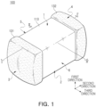
- FIG. 1 is a perspective view schematically illustrating a multilayer electronic component according to an example embodiment of the present disclosure.
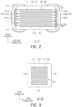
- FIG. 2 is a schematic cross-sectional view taken along line I-I' of FIG. 1 .
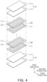
- FIG. 3 is a schematic cross-sectional view taken along line II-II' of FIG. 1 .
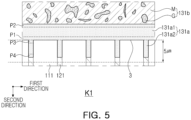
- FIG. 4 is an exploded perspective view schematically illustrating a body of FIG. 1 .
- FIG. 5 is an enlarged view of region K1 of FIG. 2 .
- a multilayer electronic component 100 according to some example embodiments of the present disclosure will be described in detail with reference to the drawings.
- a multilayer ceramic capacitor hereinafter referred to as 'MLCC'
- 'MLCC' multilayer ceramic capacitor
- the present disclosure is not limited thereto, and may be applied to various multilayer electronic components, such as inductors, piezoelectric devices, varistors, or thermistors.
- the multilayer electronic component 100 may include a dielectric layer 111 and first and second internal electrodes 121 and 122 alternately disposed in the first direction with the dielectric layer interposed therebetween, and may include a body 110 including a first surface 1 and a second surface 2 opposing each other in the first direction, a third surface 3 and a fourth surface 4 connected to the first surface and the second surface and opposing each other in the second direction, and a fifth surface 5 and a sixth surface 6 connected to the first to fourth surfaces and opposing each other in the third direction, a first external electrode 131 including a first alloy layer 131a disposed on the third surface and connected to the first internal electrode, and a second external electrode 132 disposed on the fourth surface and including a second alloy layer 132a connected to the second internal electrode, and the first and second alloy layers include alloys including Cu, Ni and Al, a molar content of Ni included in the first alloy layer may be greater than a molar content of Al in the first alloy layer, and a
- Ni of an internal electrode and Cu of an external electrode may mutually diffuse during a sintering process.
- a rate at which Cu diffuses into Ni is even faster than a rate at which Ni diffuses into Cu, a large amount of Cu may diffuse toward the internal electrode which may lead to an expansion of the volume of the internal electrode, so that there may be a risk of radiating cracks occurring in the body.
- the external electrodes 131 and 132 may be connected to the internal electrodes 121 and 122, respectively.
- the connection between the internal electrodes 121 and 122 and the external electrodes 131 and 132, respectively, may be secured by including the alloy layers 131a and 132a including alloys including Cu, Ni and Al, and simultaneously, it is possible to suppress an occurrence of radiating cracks in the body 110 by allowing Al to reduce a difference in diffusion rates between Cu and Ni.
- Al included in the alloy layers 131a and 132a has the properties of absorbing water vapor, it may be possible to improve moisture resistance reliability of the multilayer electronic component 100 by suppressing external moisture from penetrating into the body 110.
- the molar content of Ni included in the alloy layers 131a or 132a is greater than that of Al in the alloy layers 131a or 132a
- the molar content of Cu in the alloy layers 131a or 132a is greater than that of Ni in the alloy layers 131a or 132a
- a connection between the internal electrodes 121 and 122 and the external electrodes 131 and 132 may be improved, and a suppression effect of the radiating cracks may be more remarkably improved.
- the body 110 may have a hexahedral shape or a shape similar thereto. Due to the shrinkage of ceramic powder particles included in the body 110 during a sintering process or the polishing of corners, the body 110 is not a hexahedral shape with a complete straight line, but may have a substantially hexahedral shape.
- the body 110 may have the first surface 1 and the second surface 2 opposing each other in the first direction, the third surface 3 and the fourth surface 4 connected to the first surface 1 and the second surfaced 2 and opposing each other in the second direction, and the fifth surface 5 and the sixth surface 6 connected to the first to fourth surfaces 1, 2, 3 and 4 and opposing each other in the third direction.
- the dielectric layer 111 and the internal electrodes 121 and 122 may be alternately stacked. Since a plurality of dielectric layers 111 forming the body 110 are in a sintered state, a boundary between adjacent dielectric layers 111 may be integrated to the extent that the boundary may be difficult to identify without using a scanning electron microscope (SEM).
- SEM scanning electron microscope
- the dielectric layer 111 may be formed by manufacturing a ceramic slurry including ceramic powder particles, an organic solvent, and a binder, preparing a ceramic green sheet by applying and drying the slurry on a carrier film, and then sintering the ceramic green sheet.
- the ceramic powder particles are not particularly limited as long as they can obtain sufficient capacitance, but for example, barium titanate-based materials, lead composite perovskite-based materials, or strontium titanate-based materials can be used for the ceramic powder particles, and examples of the ceramic powder particles may include BaTiO 3 , (Ba 1-x Ca x )TiO 3 (0 ⁇ x ⁇ 1), Ba(Ti 1-y Ca y )O 3 (0 ⁇ y ⁇ 1), (Ba 1-x Ca x )(Ti 1-y Zr y )O 3 (0 ⁇ x ⁇ 1, 0 ⁇ y ⁇ 1) which is formed by partially employing calcium (Ca) and zirconium (Zr) in BaTiO 3 , or Ba(Ti 1-y Zr y )O 3 (0 ⁇ y ⁇ 1).
- An average thickness td of the dielectric layer 111 is not particularly limited. However, when the dielectric layer 111 is formed to be thin to achieve miniaturization and high capacitance of the multilayer electronic component 100, the dielectric layer 111 may be vulnerable to stress generated when a voltage is applied, which may easily generate radiating cracks in the body 110.
- the alloy layers 131a and 132a may include alloys including Cu, Ni and Al, the molar content of Ni including in the alloy layers 131a or 132a may be greater than that of Al in the alloy layers 131a or 132a, and the molar content of Cu in the alloy layers 131a or 132a is greater than that of Ni in the alloy layers 131a or 132a. Accordingly, even when the average thickness td of the dielectric layer 111 is 0.4 um or less, reliability of the multilayer electronic component may be secured.
- the average thickness td of the dielectric layer 111 refers to a size in the first direction of the dielectric layer 111 disposed between the internal electrodes 121 and 122.
- the average thickness of the dielectric layer 111 may be measured by scanning an image of the first and second directional cross-sections of the body 110 with the scanning electron microscope (SEM) of 10,000X magnification. More specifically, an average value may be measured by measuring the thickness at a plurality of points of one dielectric layer 111, for example, 30 points which are spaced apart from each other at equal intervals in the second direction. The 30 points spaced apart from each other at equal intervals may be designated in a capacitance formation portion Ac to be described below.
- the average thickness of the dielectric layer 111 may be further generalized.
- the internal electrodes 121 and 122 may be alternately disposed with the dielectric layer 111, and for example, a pair of electrodes with different polarities, i.e., the first internal electrode 121 and the second internal electrode 122, may be alternately disposed with the dielectric layer 111 interposed therebetween.
- the first internal electrode 121 and the second internal electrode 122 may be electrically separated from each other by the dielectric layer 111 disposed therebetween.
- the first internal electrode 121 may be connected to the first external electrode 131 at the third surface 3, and the second internal electrode 122 may be connected to the second external electrode 132 at the fourth surface 4.
- the internal electrodes 121 and 122 may include at least one conduct metal selected from the group consisting of nickel (Ni), copper (Cu), palladium (Pd), silver (Ag), gold (Au), platinum (Pt), tin (Sn), tungsten (W), titanium (Ti), and alloys thereof, and more preferably, may include Ni.
- the internal electrodes 121 and 122 may be formed by applying a conductive paste for internal electrodes including a conductive metal by a predetermined thickness on a ceramic green sheet and sintering the conductive paste.
- a printing method for the conductive paste for internal electrodes may be a screen-printing method or a gravure printing method, but the present disclosure is not limited thereto.
- An average thickness te of the internal electrodes 121 and 122 is not particularly limited.
- the alloy layers 131a and 132a may include Cu, Ni and Al, the molar content of Ni included in the alloy layers 131a and 132a may be greater than that of Al included in the alloy layers 131a and 132a, and the molar content of Cu included in the alloy layers 131a and 132a is greater than that of Ni included in the alloy layers 131a and 132a. Accordingly, even when the average thickness te of the internal electrodes 121 and 122 is 0.4 um or less, reliability of the multilayer electronic component may be secured.
- the average thickness te of the internal electrodes 121 and 122 denotes a size of the internal electrodes 121 and 122 in the first direction.
- the average thickness of the internal electrodes 121 and 122 may be measured by scanning an image of the first and second directional cross sections of the body 110 with a scanning electron microscope (SEM) at 10,000X magnification. More specifically, the average value may be measured by measuring the thickness at a plurality of points of one internal electrode 121 or 122, for example, 30 points which are spaced apart from each other at equal intervals in the second direction. The 30 points spaced apart from each other at equal intervals may be designated in a capacitance formation portion Ac to be described below.
- the average thickness of the internal electrodes 121 or 122 may be further generalized.
- the body 110 may include a capacitance formation portion Ac disposed inside the body 110 and having capacitance formed by including first and second internal electrodes 121 and 122 alternately disposed with the dielectric layer 111 interposed therebetween, and a first cover portion 112 and a second cover portion 113 respectively disposed on both cross-sections of the capacitance formation portion Ac opposing each other in the first direction.
- the cover portions 112 and 113 may basically serve to prevent damage to the internal electrodes due to physical or chemical stress.
- the cover portions 112 and 113 may have the same configuration as the dielectric layer 111 except that they do not include the internal electrodes.
- a thickness tc of the cover portions 112 and 113 need not be particularly limited.
- the average thickness tc of the cover portions 112 and 113 may be 20 um or less for achieve miniaturization and high capacitance of the multilayer electronic component.
- the alloy layers 131a and 132a may include alloys including Cu, Ni and Al, the molar content of Ni included in the alloy layers 131a and 132a may be greater than that of Al included in the alloy layers 131a and 132a, and the molar content of Cu included in the alloy layers 131a and 132a may be greater than that of Ni included in the alloy layers 131a and 132a, thereby securing the reliability of the multilayer electronic component.
- the average thickness of the cover portions 112 and 113 denotes an average thickness of each of the first cover portion 112 and the second cover portion 113.
- the average thickness of the cover portions 112 and 113 may mean an average size of the cover portions 112 and 113 in the first direction, and may be a value obtained by averaging sizes in the first direction measured at five points spaced apart from each other at equal intervals in the cross-section of the body 110 in the first direction and the second direction.
- the body 110 may include a first margin portion 114 and a second margin portion 115 respectively disposed on both cross-sections facing the capacitance formation portion Ac in the third direction. That is, the margin portions 114 and 115 may refer to regions between both ends of the internal electrodes 121 and 122 and boundary surfaces of the body 110 in cross-sections in which the body 110 is cut in the first direction and the third direction.
- the margin portions 114 and 115 may include the same material as the dielectric layer 111 except that they do not include the internal electrodes 121 and 122.
- the margin portions 114 and 115 may basically serve to prevent damage to the internal electrodes 121 and 122 due to physical or chemical stress.
- the margin portions 114 and 115 may be formed by applying and firing a conductive paste for an internal electrode except for a position in which the margin portions will be formed on the ceramic green sheet.
- the internal electrodes 121 and 122 may be stacked and then cut to be connected to the fifth surface 5 and the sixth surface 6 of the body, and then, the margin portions 114 and 115 may be formed by stacking a single dielectric layer or two or more dielectric layers on both cross-sections of the capacitance formation portion Ac opposing each other in the third direction.
- an average thickness of the margin portions 114 and 115 need not be particularly limited. However, for achieving miniaturization and high capacitance of the multilayer electronic component, the average thickness of the margin portions 114 and 115 may be 20 um or less. As described above, even when the average thickness of the margin portions 114 and 115 is 20 um or less, the alloy layers 131a and 132a include alloys including Cu, Ni and Al, the molar content of Ni included in the alloy layers 131a and 132a may be greater than that of Al included in the alloy layers 131a and 132a, and the molar content of Cu included in the alloy layers 131a and 132a may be greater than that of Ni included in the alloy layers 131a and 132a, thereby ensuring reliability of the multilayer electronic component.
- the average thickness of the margin portions 114 and 115 denote an average thickness of each of the first machining portion 114 and the second machining portion 115.
- the average thickness of the margin portions 114 and 115 may denote an average size of the margin portions 114 and 115 in the third direction, and may be a value obtained by averaging sizes in the third direction measured at five points spaced apart from each other at equal intervals in the cross-sections of the body 110 in first direction and the third direction.
- the external electrodes 131 and 132 may be disposed on the third surface 3 and the fourth surface and 4 of the body 110, and may extend over a portion of the first surface, the second surface, the fifth surface, and the sixth surface. Furthermore, the external electrodes 131 and 132 may include a first external electrode 131 connected to the first internal electrode 121 and a second external electrode 132 connected to the second internal electrode 122.
- the external electrodes 131 and 132 may respectively include alloy layers 131a and 132a connected to the internal electrodes 121 and 122, and electrode layers 131b and 132b respectively disposed on the alloy layers 131a and 132a. That is, the first external electrode 131 may include a first alloy layer 131a disposed on the third surface 3 and connected to the first internal electrode 121, and a first electrode layer 131b disposed on the first alloy layer, and the second external electrode 132 may include a second alloy layer 132a disposed on the fourth surface 4 and connected to the second internal electrode 122 and a second electrode layer 132b disposed on the second alloy layer. As illustrated in FIG. 2 , the first alloy layer 131a may be in contact with the first internal electrode 121 in the body 110, and the second alloy layer 132a may be in contact with the second internal electrode 122 in the body 110.
- first external electrode 131 may include a first plating layer 131c disposed on the first electrode layer
- second external electrode 132 may include a second plating layer 132c disposed on the second electrode layer.
- the present disclosure is not limited thereto, and the number or shape of the external electrodes 131 and 132 may be changed according to the shape or other purpose of the internal electrodes 121 and 122.
- the first and second electrode layers 131b and 132b may extend from the first and second alloy layers 131a and 132a onto at least a portion of the first surface 1 and the second surface 2. Furthermore, the first and second electrode layers 131b and 132b may extend from the first and second alloy layers 131a and 132a to at least a portion of the fifth surface 5 and the sixth surface 6.
- the first and second electrode layers 131b and 132b may include metal and glass.
- a metal M included in the first electrode layer 131b may serve to ensure an electrical connection with the first alloy layer 131a
- a glass G included in the first electrode layer 131b may serve to secure bonding force between the body 110 and the external electrodes 131 and 132.
- the metal M included in the first and second electrode layers 131b and 132b may be selected from the group consisting of copper (Cu), nickel (Ni), palladium (Pd), platinum (Pt), gold (Au), silver (Ag), lead (Pb), and alloys thereof, and more preferably, may include Cu.
- Each of the alloy layers 131a and 132a may include alloys including Cu, Ni and Al.
- Cu included in the alloy layers 131a and 132a may be derived from the electrode layers 131b and 132b, and Ni included in the alloy layers 131a and 132a may be derived from the internal electrodes 121 and 122. That is, the alloy layers 131a and 132a may be formed by mutually diffusing Cu included in the electrode layers 131b and 132b and Ni included in the internal electrodes 121 and 122 during a sintering process of the electrode layers 131b and 132b.
- the alloy layers 131a and 132a may basically serve to improve the connection between the internal electrodes 121 and 122 and the external electrodes 131 and 132, thereby improving electrical characteristics of the multilayer electronic component.
- a method of forming the alloy layers 131a and 132a and the electrode layers 131b and 132b need not be particularly limited.
- the electrode layers 131b and 132b may be formed by dipping the third surface 3 and the fourth surface 4 of the body 110 into a conductive paste containing Cu particles and glass and then sintering the conductive paste.
- Cu particles coated with Al 2 O 3 when used as Cu particles included in the conductive paste, Cu included in the electrode layers 131b and 132b and Ni included in the internal electrodes 121 and 122 may be mutually diffused during the sintering process, but Al coated on Cu may reduce a diffusion rate of Cu to reduce a difference in a mutual diffusion rate between Cu and Ni, thereby suppressing the occurrence of the radiating cracks in the body 110.
- the first and second alloy layers 131a and 132a may be disposed between an extension line E1 of the first surface and an extension line E2 of the second surface.
- the extension line of each surface may denote a line extending from a flat portion of each surface. Since the alloy layers 131a and 132a are formed by mutually diffusing Cu and Al of the electrode layers 131b and 132b and Ni of the internal electrodes 121 and 122 during the sintering process, the first and second alloy layers 131a and 132a may be disposed between the extension line E1 of the first surface and the extension line E2 of the second surface, and may not extend onto the first surface 1 and/or the second surface 2 of the body 110.
- the first alloy layer 131a merely differs from the second alloy layer 132a in that the first alloy layer 131a is connected to the first internal electrode 121, and the second alloy layer 132a is connected to the second internal electrode, and the first alloy layer 131a and the second alloy layer 132a have similar configurations, and accordingly, the description of the first alloy layer 131a below may be considered to include the description of the second alloy layer 132a.
- a molar content of Cu included in the first alloy layer 131a may be greater than a molar content of Ni.
- Ni has a property that oxidizes more easily than Cu
- the connection between the first internal electrode 121 and the first external electrode 131 may be reduced due to the formation of a Ni oxide, which may increase equivalent series resistance (ESR).
- the molar content of Ni included in the first alloy layer 131a may be greater than the molar content of Al.
- the molar content of Al included in the first alloy layer 131a is greater than that of Ni, the diffusion of Cu and the formation of alloys therethrough may be excessively suppressed, and accordingly, the effect of improving the connection between the internal electrodes and the external electrodes of the present disclosure may be insignificant. That is, in the case of the disclosure, because the first alloy layer 131a satisfies the molar content of Cu > the molar content of Ni > the molar content of Al, the effect of improving the connection between the internal electrodes and the external electrodes and suppressing the radiating cracks may be more remarkably enhanced.
- a molar ratio of an Al content to a total content of Cu, Ni and Al included in the first alloy layer 131a may be 0.001 to 0.005.
- the effect of preventing the radiating cracks in the present disclosure may be insignificant.
- the molar ratio of the Al content to the total content of Cu, Ni and Al exceeds 0.005, the effect of improving the connection between the internal electrodes and the external electrodes of the present disclosure may be insignificant.
- a molar ratio of a Cu content to the total content of Cu, Ni and Al included in the first alloy layer 131a is not particularly limited, but may be, for example, 0.504 or more and 0.881 or less. Furthermore, a molar ratio of a Ni content to the total content of Cu, Ni and Al contained in the first alloy layer 131a does not need to be particularly limited, but may be, for example, 0.117 or more and 0.495 or less.
- the molar content of each of Cu, Ni and Al included in the first alloy layer 131a may be measured, for example, by obtaining images captured with a scanning electron microscope (SEM) of the first and second directional cross sections of the multilayer electron component 100 cut in the center of the body the third direction, and then analyzing the components through the image using energy dispersive spectroscopy (EDS).
- SEM scanning electron microscope
- EDS energy dispersive spectroscopy
- the first alloy layer 131a may include a first external alloy layer 131a1 continuously disposed on the third surface 3 to form one layer, and a plurality of first internal alloy layers 131a2 extending from the first external alloy layer into the body 110 and coming into contact with the first internal electrode 121.
- the first external alloy layer 131a1 may be formed by diffusing Ni of the first internal electrode 121 toward the first electrode layer 131b, and the first internal alloy layer 131a2 may be formed by diffusing Cu and Al of the first electrode layer 131b toward the first internal electrode 121.
- Al included in the first alloy layer 131a may reduce a diffusion rate of Cu to easily diffuse Ni included in the first internal electrode 121 toward the first electrode layer 131b, so that the first external alloy layer 131a1 may form one layer on the third surface 3.
- a size of the first internal alloy layer 131a2 in the second direction may be 5 um or less.
- the thickness of the first internal alloy layer 131a2 in the second direction is 5 um or less, it may be possible to more effectively prevent the radiating cracks from occurring in the body 110 by causing Cu of the first electrode layer 131b to penetrate excessively into the first internal electrode 121.
- the thickness of the first internal alloy layer 131a2 in the second direction may denote a distance in the second direction by one end of the first internal alloy layer 131a2 coming into contact with the first internal electrode 121 from the third surface 3.
- SEM-EDS Scanning Electron Microscopy - Energy-Dispersive X-ray Spectrometry
- one end of the first internal alloy layer 131a2 in contact with the first internal electrode 121 may be specified as a boundary between a region that satisfies the molar content of Cu > the molar content of Ni > the molar content of Al and a region that does not satisfy the molar content of Cu > the molar content of Ni > the molar content of Al.
- the SEM-EDS may be performed on first and second directional cross-sections cut in a center of the multilayer electronic component in the third direction, and the cross-sections of the multilayer electronic component may be observed by molding the multilayer electronic component with epoxy and then flattening a surface thereof by ion milling.
- a thickness of one first internal alloy layer 131a2 in the second direction may be measured as follow. First, a virtual line connecting the first directional center points of each one end in contact with the first external electrode 131 of two dielectric layers 111, with one first internal alloy layer 131a2 interposed therebetween, can be drawn.
- a straight line in parallel with the second direction from a first directional center point of one end of the first internal allow layer 131a2 in contact with the first internal electrode 121 toward the virtual line can be drawn.
- the thickness of one first internal alloy layer 131a2 in the second direction may be defined as a distance between a point in which the virtual line and the straight line meet and the first directional center point of one end of the first internal alloy layer 131a2.
- a region P1 of the first external alloy layer 131a1 adjacent to the first internal alloy layer may have a molar content of Ni greater than that of a region P2 of the first external alloy layer 131a1 adjacent to an external side of the first external alloy layer. This is because Ni included in the first external alloy layer 131a1 is diffused from the first internal electrode 121.
- a region P3 of the first internal alloy layer 131a2 adjacent to the first external alloy layer 131a1 may have a molar content of Cu greater than a region P4 of the first internal alloy layer 131a2 adjacent to the first internal electrode 121. This is because Cu included in the first internal alloy layer 131a2 is diffused from the first electrode layer 131b.
- the type of the plating layers 131c and 132c is not particularly limited, and may include at least one selected from the group consisting of nickel (Ni), tin (Sn), palladium (Pd), and alloys thereof, or may include a plurality of layers.
- the plating layers 131c and 132c may include, for example, a nickel (Ni) plating layer or a tin (Sn) plating layer, and may include the nickel (Ni) plating layer and the tin (Sn) plating layer sequentially formed.
- the plating layers 131c and 132c may include a plurality of nickel (Ni) plating layers and/or a plurality of tin (Sn) plating layers.
- a multilayer electronic component 100 may include a dielectric layer 111 and first and second internal electrodes 121 and 122 alternately disposed in the first direction with the dielectric layer interposed therebetween, and may include a body including a first surface 1 and a second surface 2 opposing each other in the first direction, a third surface 3 and a fourth surface 4 connected to the first surface and the second surface and opposing each other in the second direction, and a fifth surface 5 and a sixth surface 6 connected to the first surface to the fourth surface and opposing each other in the third direction, a first external electrode 131 disposed on the third surface and including a first alloy layer 131a in contact with the first internal electrode in the body, and a second external electrode 132 disposed on the fourth surface and including a second alloy layer 132a in contact with the second internal electrode in the body, and the first and second alloy layers 131a and 132a may include alloys including Cu, Ni and Al, and a thickness of the first alloy layer 131a in a region in which
- the first and second alloy layers 131a and 132a may include Cu, Ni and Al and may basically serve to improve a connection between the internal electrodes 121 and 122 and the external electrodes 131 and 132, thus improving the electrical characteristics of multilayer electronic components, and the alloys may include Al to reduce a difference in a diffusion rate between Cu and Ni, thus suppressing an occurrence of radiating cracks in the body 110.
- the first internal electrode 121 and the first alloy layer 131a are in contact with each other is within 5 um from the third surface in the second direction, it may be possible to more effectively prevent the radiating cracks from occurring in the body 110 by causing Cu of the first electrode layer 131b to penetrating excessively into the first internal electrode 121.
- a region in which the first internal electrode 121 and the first alloy layer 131a are in contact with each other may be specified as a boundary between a region that satisfies the molar content of Cu > the molar content of Ni > the molar content of Al and a region that does not satisfy the molar content of Cu > the molar content of Ni > the molar content of Al.
- the SEM-EDS may be performed on first and second directional cross-sections cut in a center of the multilayer electronic component in the third direction, and the cross-sections of the multilayer electronic component may be observed by molding the multilayer electronic component with epoxy and then flattening a surface thereof by ion milling.
- a contact region between the first internal electrode 121 and the first alloy layer 131a within 5 um from the third surface in the second direction may denote as a distance between a point in which a virtual line and a straight line in parallel with the second direction meet and the first directional center point of a region in which the first internal electrode 121 and the first alloy layer 131a are in contact with each other may be 5 um or less when drawing the virtual line for connecting the first directional center points of each end in contact with the first external electrodes 131 of two dielectric layers 111 with one first alloy layer 131a disposed in the body 110 interposed therebetween, and drawing a straight line in parallel with the second direction toward the virtual line from the first directional center point of a region in which the first internal electrode 121 and the first alloy layer 131a are in contact with each other.
- an example embodiment' used in the present disclosure does not denote the same example embodiment, and is provided to emphasize and explain different unique characteristics.
- the example embodiments presented above do not preclude being implemented in combination with the features of another embodiment.
- the items described in a specific embodiment are not described in another embodiment, the items may be understood as a description related to another embodiment unless a description opposite or contradictory to the items is in another embodiment.
- first and second are used to distinguish one component from another, and do not limit the order and/or importance of the components.
- a first component may be referred to as a second component without departing from the scope of rights, or similarly, the second component may be referred to as the first component.
Landscapes
- Engineering & Computer Science (AREA)
- Power Engineering (AREA)
- Manufacturing & Machinery (AREA)
- Microelectronics & Electronic Packaging (AREA)
- Chemical & Material Sciences (AREA)
- Ceramic Engineering (AREA)
- Inorganic Chemistry (AREA)
- Materials Engineering (AREA)
- Structural Engineering (AREA)
- Organic Chemistry (AREA)
- Fixed Capacitors And Capacitor Manufacturing Machines (AREA)
- Ceramic Capacitors (AREA)
Applications Claiming Priority (1)
| Application Number | Priority Date | Filing Date | Title |
|---|---|---|---|
| KR1020230017529A KR20240124717A (ko) | 2023-02-09 | 2023-02-09 | 적층형 전자 부품 |
Publications (3)
| Publication Number | Publication Date |
|---|---|
| EP4415013A2 true EP4415013A2 (de) | 2024-08-14 |
| EP4415013A3 EP4415013A3 (de) | 2025-01-15 |
| EP4415013B1 EP4415013B1 (de) | 2025-08-13 |
Family
ID=89723302
Family Applications (1)
| Application Number | Title | Priority Date | Filing Date |
|---|---|---|---|
| EP24153957.6A Active EP4415013B1 (de) | 2023-02-09 | 2024-01-25 | Mehrschichtiges keramisches elektronikbauteil mit einer interdigitalen metallzwischenschicht zwischen der inneren und der äusseren elektrode |
Country Status (5)
| Country | Link |
|---|---|
| US (1) | US20240274363A1 (de) |
| EP (1) | EP4415013B1 (de) |
| JP (1) | JP2024113669A (de) |
| KR (1) | KR20240124717A (de) |
| CN (1) | CN118471688A (de) |
Family Cites Families (10)
| Publication number | Priority date | Publication date | Assignee | Title |
|---|---|---|---|---|
| US5163209A (en) * | 1989-04-26 | 1992-11-17 | Hitachi, Ltd. | Method of manufacturing a stack-type piezoelectric element |
| JP3874041B2 (ja) * | 1997-08-18 | 2007-01-31 | Tdk株式会社 | Cr複合電子部品とその製造方法 |
| JP3827060B2 (ja) * | 2000-09-25 | 2006-09-27 | 昭栄化学工業株式会社 | 積層セラミック部品端子電極用導体ペースト |
| JP2008042068A (ja) * | 2006-08-09 | 2008-02-21 | Matsushita Electric Ind Co Ltd | 積層コンデンサとその製造方法 |
| JP2015035581A (ja) * | 2013-07-10 | 2015-02-19 | 株式会社村田製作所 | セラミック電子部品およびその製造方法 |
| JP6020502B2 (ja) * | 2014-03-31 | 2016-11-02 | 株式会社村田製作所 | 積層セラミック電子部品 |
| JP6679964B2 (ja) * | 2015-03-12 | 2020-04-15 | 株式会社村田製作所 | 積層セラミックコンデンサ |
| JP7475259B2 (ja) * | 2018-05-16 | 2024-04-26 | 株式会社村田製作所 | チップ型セラミック電子部品 |
| JP7231340B2 (ja) * | 2018-06-05 | 2023-03-01 | 太陽誘電株式会社 | セラミック電子部品およびその製造方法 |
| JP2021100020A (ja) * | 2019-12-20 | 2021-07-01 | 太陽誘電株式会社 | 積層セラミック電子部品及びその製造方法 |
-
2023
- 2023-02-09 KR KR1020230017529A patent/KR20240124717A/ko active Pending
-
2024
- 2024-01-25 EP EP24153957.6A patent/EP4415013B1/de active Active
- 2024-01-29 JP JP2024011005A patent/JP2024113669A/ja active Pending
- 2024-01-29 US US18/425,336 patent/US20240274363A1/en active Pending
- 2024-02-07 CN CN202410174137.2A patent/CN118471688A/zh active Pending
Also Published As
| Publication number | Publication date |
|---|---|
| CN118471688A (zh) | 2024-08-09 |
| JP2024113669A (ja) | 2024-08-22 |
| EP4415013B1 (de) | 2025-08-13 |
| US20240274363A1 (en) | 2024-08-15 |
| KR20240124717A (ko) | 2024-08-19 |
| EP4415013A3 (de) | 2025-01-15 |
Similar Documents
| Publication | Publication Date | Title |
|---|---|---|
| US20130229748A1 (en) | Multilayer ceramic electronic component and method of manufacturing the same | |
| US20130258546A1 (en) | Multilayer ceramic electronic component and fabrication method thereof | |
| US11361905B2 (en) | Multi-layered ceramic electronic component | |
| US20250140478A1 (en) | Multilayer electronic component | |
| EP4401104A2 (de) | Mehrschichtiges elektronisches bauteil | |
| US12278056B2 (en) | Multilayer electronic component | |
| EP4415013B1 (de) | Mehrschichtiges keramisches elektronikbauteil mit einer interdigitalen metallzwischenschicht zwischen der inneren und der äusseren elektrode | |
| US12230449B2 (en) | Multilayer electronic component | |
| EP4560664A2 (de) | Äussere elektroden für ein mehrschichtiges keramisches bauteil mit einer schicht aus borosilikatglas an seinem oberen und unteren ende | |
| US20250125097A1 (en) | Multilayer electronic component | |
| EP4415012A1 (de) | Mehrschichtiges elektronisches bauteil | |
| EP4604149A1 (de) | Mehrschichtiges elektronisches bauteil | |
| EP4535385A1 (de) | Mehrschichtiges elektronisches bauteil | |
| EP4557338A1 (de) | Mehrschichtiges elektronisches bauteil | |
| US20250218681A1 (en) | Multilayer electronic component | |
| US20240212935A1 (en) | Multilayer electronic component | |
| US12340944B2 (en) | Multilayer electronic component | |
| EP4560668A1 (de) | Mehrschichtiges elektronisches bauteil | |
| EP4553867A2 (de) | Aussenelektroden für keramische mehrschichtkondensatoren mit einer zwischenschicht aus einer teilweise oxidierten silber- (ag) und (cu) kupferlegierung | |
| US20250218689A1 (en) | Multilayer electronic component | |
| EP4553870A1 (de) | Aussenelektroden für einen mehrschichtigen keramischen kondensator mit einer ersten kupferbasierten elektrode, gefolgt von einer schwach porösen zwischenschicht aus einer silber-kupfer-basierenden legierung mit einer silberbasierten zwischenelektrode | |
| EP4535383A1 (de) | Mehrschichtiges elektronisches bauteil | |
| EP4506972A2 (de) | Keramischer vielschichtkondensator mit inneren halbelektroden, die teilweise von einheitselektroden bedeckt sind | |
| US20250201480A1 (en) | Multilayer electronic component | |
| US20240274355A1 (en) | Multilayer electronic component |
Legal Events
| Date | Code | Title | Description |
|---|---|---|---|
| PUAI | Public reference made under article 153(3) epc to a published international application that has entered the european phase |
Free format text: ORIGINAL CODE: 0009012 |
|
| STAA | Information on the status of an ep patent application or granted ep patent |
Free format text: STATUS: REQUEST FOR EXAMINATION WAS MADE |
|
| 17P | Request for examination filed |
Effective date: 20240125 |
|
| AK | Designated contracting states |
Kind code of ref document: A2 Designated state(s): AL AT BE BG CH CY CZ DE DK EE ES FI FR GB GR HR HU IE IS IT LI LT LU LV MC ME MK MT NL NO PL PT RO RS SE SI SK SM TR |
|
| PUAL | Search report despatched |
Free format text: ORIGINAL CODE: 0009013 |
|
| AK | Designated contracting states |
Kind code of ref document: A3 Designated state(s): AL AT BE BG CH CY CZ DE DK EE ES FI FR GB GR HR HU IE IS IT LI LT LU LV MC ME MK MT NL NO PL PT RO RS SE SI SK SM TR |
|
| RIC1 | Information provided on ipc code assigned before grant |
Ipc: H01G 4/012 20060101ALI20241210BHEP Ipc: H01G 4/008 20060101ALI20241210BHEP Ipc: H01G 4/12 20060101ALI20241210BHEP Ipc: H01G 4/30 20060101ALI20241210BHEP Ipc: H01G 4/232 20060101AFI20241210BHEP |
|
| GRAP | Despatch of communication of intention to grant a patent |
Free format text: ORIGINAL CODE: EPIDOSNIGR1 |
|
| STAA | Information on the status of an ep patent application or granted ep patent |
Free format text: STATUS: GRANT OF PATENT IS INTENDED |
|
| INTG | Intention to grant announced |
Effective date: 20250321 |
|
| GRAS | Grant fee paid |
Free format text: ORIGINAL CODE: EPIDOSNIGR3 |
|
| GRAA | (expected) grant |
Free format text: ORIGINAL CODE: 0009210 |
|
| STAA | Information on the status of an ep patent application or granted ep patent |
Free format text: STATUS: THE PATENT HAS BEEN GRANTED |
|
| P01 | Opt-out of the competence of the unified patent court (upc) registered |
Free format text: CASE NUMBER: APP_29559/2025 Effective date: 20250622 |
|
| AK | Designated contracting states |
Kind code of ref document: B1 Designated state(s): AL AT BE BG CH CY CZ DE DK EE ES FI FR GB GR HR HU IE IS IT LI LT LU LV MC ME MK MT NL NO PL PT RO RS SE SI SK SM TR |
|
| REG | Reference to a national code |
Ref country code: GB Ref legal event code: FG4D |
|
| RIN1 | Information on inventor provided before grant (corrected) |
Inventor name: KOO, KUN HOI Inventor name: KIM, SOUNG JIN Inventor name: YI, YOUNG SOO Inventor name: KYEONG, SAN Inventor name: KIM, YUN HEE |
|
| REG | Reference to a national code |
Ref country code: CH Ref legal event code: EP |
|
| REG | Reference to a national code |
Ref country code: DE Ref legal event code: R096 Ref document number: 602024000417 Country of ref document: DE |
|
| REG | Reference to a national code |
Ref country code: IE Ref legal event code: FG4D |
|
| REG | Reference to a national code |
Ref country code: NL Ref legal event code: MP Effective date: 20250813 |
|
| PG25 | Lapsed in a contracting state [announced via postgrant information from national office to epo] |
Ref country code: IS Free format text: LAPSE BECAUSE OF FAILURE TO SUBMIT A TRANSLATION OF THE DESCRIPTION OR TO PAY THE FEE WITHIN THE PRESCRIBED TIME-LIMIT Effective date: 20251213 |
|
| PG25 | Lapsed in a contracting state [announced via postgrant information from national office to epo] |
Ref country code: NO Free format text: LAPSE BECAUSE OF FAILURE TO SUBMIT A TRANSLATION OF THE DESCRIPTION OR TO PAY THE FEE WITHIN THE PRESCRIBED TIME-LIMIT Effective date: 20251113 |
|
| REG | Reference to a national code |
Ref country code: LT Ref legal event code: MG9D |
|
| PG25 | Lapsed in a contracting state [announced via postgrant information from national office to epo] |
Ref country code: PT Free format text: LAPSE BECAUSE OF FAILURE TO SUBMIT A TRANSLATION OF THE DESCRIPTION OR TO PAY THE FEE WITHIN THE PRESCRIBED TIME-LIMIT Effective date: 20251215 |
|
| PG25 | Lapsed in a contracting state [announced via postgrant information from national office to epo] |
Ref country code: FI Free format text: LAPSE BECAUSE OF FAILURE TO SUBMIT A TRANSLATION OF THE DESCRIPTION OR TO PAY THE FEE WITHIN THE PRESCRIBED TIME-LIMIT Effective date: 20250813 |
|
| PG25 | Lapsed in a contracting state [announced via postgrant information from national office to epo] |
Ref country code: HR Free format text: LAPSE BECAUSE OF FAILURE TO SUBMIT A TRANSLATION OF THE DESCRIPTION OR TO PAY THE FEE WITHIN THE PRESCRIBED TIME-LIMIT Effective date: 20250813 Ref country code: NL Free format text: LAPSE BECAUSE OF FAILURE TO SUBMIT A TRANSLATION OF THE DESCRIPTION OR TO PAY THE FEE WITHIN THE PRESCRIBED TIME-LIMIT Effective date: 20250813 |
|
| PG25 | Lapsed in a contracting state [announced via postgrant information from national office to epo] |
Ref country code: GR Free format text: LAPSE BECAUSE OF FAILURE TO SUBMIT A TRANSLATION OF THE DESCRIPTION OR TO PAY THE FEE WITHIN THE PRESCRIBED TIME-LIMIT Effective date: 20251114 |
|
| PG25 | Lapsed in a contracting state [announced via postgrant information from national office to epo] |
Ref country code: SE Free format text: LAPSE BECAUSE OF FAILURE TO SUBMIT A TRANSLATION OF THE DESCRIPTION OR TO PAY THE FEE WITHIN THE PRESCRIBED TIME-LIMIT Effective date: 20250813 |
|
| PG25 | Lapsed in a contracting state [announced via postgrant information from national office to epo] |
Ref country code: LV Free format text: LAPSE BECAUSE OF FAILURE TO SUBMIT A TRANSLATION OF THE DESCRIPTION OR TO PAY THE FEE WITHIN THE PRESCRIBED TIME-LIMIT Effective date: 20250813 |
|
| PG25 | Lapsed in a contracting state [announced via postgrant information from national office to epo] |
Ref country code: BG Free format text: LAPSE BECAUSE OF FAILURE TO SUBMIT A TRANSLATION OF THE DESCRIPTION OR TO PAY THE FEE WITHIN THE PRESCRIBED TIME-LIMIT Effective date: 20250813 Ref country code: PL Free format text: LAPSE BECAUSE OF FAILURE TO SUBMIT A TRANSLATION OF THE DESCRIPTION OR TO PAY THE FEE WITHIN THE PRESCRIBED TIME-LIMIT Effective date: 20250813 |
|
| PG25 | Lapsed in a contracting state [announced via postgrant information from national office to epo] |
Ref country code: RS Free format text: LAPSE BECAUSE OF FAILURE TO SUBMIT A TRANSLATION OF THE DESCRIPTION OR TO PAY THE FEE WITHIN THE PRESCRIBED TIME-LIMIT Effective date: 20251113 |
|
| PG25 | Lapsed in a contracting state [announced via postgrant information from national office to epo] |
Ref country code: ES Free format text: LAPSE BECAUSE OF FAILURE TO SUBMIT A TRANSLATION OF THE DESCRIPTION OR TO PAY THE FEE WITHIN THE PRESCRIBED TIME-LIMIT Effective date: 20250813 |