EP4414753A1 - Posture adjustment structure, transmission device, and radiation imaging system - Google Patents
Posture adjustment structure, transmission device, and radiation imaging system Download PDFInfo
- Publication number
- EP4414753A1 EP4414753A1 EP22826794.4A EP22826794A EP4414753A1 EP 4414753 A1 EP4414753 A1 EP 4414753A1 EP 22826794 A EP22826794 A EP 22826794A EP 4414753 A1 EP4414753 A1 EP 4414753A1
- Authority
- EP
- European Patent Office
- Prior art keywords
- detected object
- base body
- rack
- adjustment assembly
- adjustment structure
- Prior art date
- Legal status (The legal status is an assumption and is not a legal conclusion. Google has not performed a legal analysis and makes no representation as to the accuracy of the status listed.)
- Pending
Links
Images


Classifications
-
- G—PHYSICS
- G01—MEASURING; TESTING
- G01N—INVESTIGATING OR ANALYSING MATERIALS BY DETERMINING THEIR CHEMICAL OR PHYSICAL PROPERTIES
- G01N23/00—Investigating or analysing materials by the use of wave or particle radiation, e.g. X-rays or neutrons, not covered by groups G01N3/00 – G01N17/00, G01N21/00 or G01N22/00
- G01N23/02—Investigating or analysing materials by the use of wave or particle radiation, e.g. X-rays or neutrons, not covered by groups G01N3/00 – G01N17/00, G01N21/00 or G01N22/00 by transmitting the radiation through the material
- G01N23/04—Investigating or analysing materials by the use of wave or particle radiation, e.g. X-rays or neutrons, not covered by groups G01N3/00 – G01N17/00, G01N21/00 or G01N22/00 by transmitting the radiation through the material and forming images of the material
- G01N23/046—Investigating or analysing materials by the use of wave or particle radiation, e.g. X-rays or neutrons, not covered by groups G01N3/00 – G01N17/00, G01N21/00 or G01N22/00 by transmitting the radiation through the material and forming images of the material using tomography, e.g. computed tomography [CT]
-
- B—PERFORMING OPERATIONS; TRANSPORTING
- B65—CONVEYING; PACKING; STORING; HANDLING THIN OR FILAMENTARY MATERIAL
- B65G—TRANSPORT OR STORAGE DEVICES, e.g. CONVEYORS FOR LOADING OR TIPPING, SHOP CONVEYOR SYSTEMS OR PNEUMATIC TUBE CONVEYORS
- B65G47/00—Article or material-handling devices associated with conveyors; Methods employing such devices
- B65G47/22—Devices influencing the relative position or the attitude of articles during transit by conveyors
-
- G—PHYSICS
- G01—MEASURING; TESTING
- G01N—INVESTIGATING OR ANALYSING MATERIALS BY DETERMINING THEIR CHEMICAL OR PHYSICAL PROPERTIES
- G01N23/00—Investigating or analysing materials by the use of wave or particle radiation, e.g. X-rays or neutrons, not covered by groups G01N3/00 – G01N17/00, G01N21/00 or G01N22/00
- G01N23/02—Investigating or analysing materials by the use of wave or particle radiation, e.g. X-rays or neutrons, not covered by groups G01N3/00 – G01N17/00, G01N21/00 or G01N22/00 by transmitting the radiation through the material
- G01N23/04—Investigating or analysing materials by the use of wave or particle radiation, e.g. X-rays or neutrons, not covered by groups G01N3/00 – G01N17/00, G01N21/00 or G01N22/00 by transmitting the radiation through the material and forming images of the material
-
- G—PHYSICS
- G01—MEASURING; TESTING
- G01N—INVESTIGATING OR ANALYSING MATERIALS BY DETERMINING THEIR CHEMICAL OR PHYSICAL PROPERTIES
- G01N2223/00—Investigating materials by wave or particle radiation
- G01N2223/30—Accessories, mechanical or electrical features
- G01N2223/32—Accessories, mechanical or electrical features adjustments of elements during operation
-
- G—PHYSICS
- G01—MEASURING; TESTING
- G01N—INVESTIGATING OR ANALYSING MATERIALS BY DETERMINING THEIR CHEMICAL OR PHYSICAL PROPERTIES
- G01N2223/00—Investigating materials by wave or particle radiation
- G01N2223/30—Accessories, mechanical or electrical features
- G01N2223/321—Accessories, mechanical or electrical features manipulator for positioning a part
-
- G—PHYSICS
- G01—MEASURING; TESTING
- G01N—INVESTIGATING OR ANALYSING MATERIALS BY DETERMINING THEIR CHEMICAL OR PHYSICAL PROPERTIES
- G01N2223/00—Investigating materials by wave or particle radiation
- G01N2223/30—Accessories, mechanical or electrical features
- G01N2223/33—Accessories, mechanical or electrical features scanning, i.e. relative motion for measurement of successive object-parts
- G01N2223/3306—Accessories, mechanical or electrical features scanning, i.e. relative motion for measurement of successive object-parts object rotates
-
- G—PHYSICS
- G01—MEASURING; TESTING
- G01N—INVESTIGATING OR ANALYSING MATERIALS BY DETERMINING THEIR CHEMICAL OR PHYSICAL PROPERTIES
- G01N2223/00—Investigating materials by wave or particle radiation
- G01N2223/30—Accessories, mechanical or electrical features
- G01N2223/33—Accessories, mechanical or electrical features scanning, i.e. relative motion for measurement of successive object-parts
- G01N2223/3307—Accessories, mechanical or electrical features scanning, i.e. relative motion for measurement of successive object-parts source and detector fixed; object moves
Definitions
- the present disclosure relates to a field of detection apparatus technology, and in particular, to an attitude adjustment structure, a conveying device, and a radiation imaging system.
- Radiation imaging is a technology to observe an inside of an object using rays. Such technology may obtain information such as the structure and density of the inside of the object without destroying the object, and is currently widely used in scenarios such as chest X-rays in hospitals and security inspections in stations and airports.
- a detected object is a thin film or an adhesive layer, in order to ensure the accuracy of detection, it is necessary that a main beam plane of a light beam generated by a ray machine in a radiation imaging system be parallel to a detected layer of the detected object.
- an attitude adjustment structure a conveying device, and a radiation imaging system.
- an attitude adjustment structure including: a base body, arranged in an X direction, the base body having a bearing surface, and the bearing surface being configured to place a detected object; a first adjustment assembly, arranged on the base body and configured to drive the detected object to deviate around a Y direction on the bearing surface and drive the detected object to move in the X direction; and at least one second adjustment assembly, arranged on the base body and configured to drive the detected object to rotate around a Z direction.
- the first adjustment assembly includes: a rack, slidable in the X direction relative to the base body; and a rotating member, rotatably arranged on the rack with the Y axis as a rotation axis and configured to drive the detected object to deviate around the Y direction on the bearing surface under a driving of an external force, and drive the detected object to move in the X direction under a driving of the rack.
- the rotating member includes: a turning lever, rotatably arranged on the rack with the Y axis as a rotation axis; and a turning head, arranged on the turning lever and allowed to abut against the detected object under a driving of the driving rod.
- the rack is provided with a rotating shaft protruding in the Y direction
- the first adjustment assembly further includes: an adapter block rotatably arranged on the rotating shaft, the driving lever being fixed on the adapter block.
- the first adjustment assembly further includes: at least one first driving unit, arranged on the rack, the first driving unit having a pushing rod movable toward or away from the adapter block, wherein, the pushing rod is movably connected to an end of the adapter block away from the rotating shaft.
- the first driving unit further includes: a first motor, arranged on the rack, an end of the pushing rod is connected to a motor shaft of the first motor; wherein an end of the pushing rod close to the adapter block is provided with a threaded section, and the adapter block is provided with a thread sleeve matched with the threaded section.
- At least one of the turning head is rotatably arranged on the turning lever and is configured as an eccentric structure, wherein, the turning head has a first position protruding from the bearing surface under a driving of an eccentric force and a second position turned below the bearing surface under an action of an external force; and when the rack moves in the X direction, the turning head at the first position is configured to push the detected object to move in the X direction.
- the turning head has: a pushing surface configured to abut against the detected object; a guiding surface, arranged at an angle to the pushing surface and configured to receive an external force; a limiting structure, configured to limit a rotation of the turning heat when the turning head moves to the first position; wherein, when the rack moves in a negative direction of the X axis, the guiding surface hits the detected object to drive the turning head to move to the second position.
- the attitude adjustment structure further includes: a balancing weight, arranged on the turning head and configured to adjust an eccentric distance of the turning head, so that the pushing surface is parallel to a YZ plane at the first position.
- a plurality of the turning heads are rotatably arranged on the rack, and the plurality of the turning heads are arranged at intervals, so as to push the detected object on the base body to move toward a detection region.
- a sliding rail-sliding block structure is arranged between the rack and the base body.
- the detected object is conveyed to the second adjustment assembly under a driving of the first adjustment assembly
- the second adjustment assembly includes: a supporting plate, rotatably arranged on the base body with the Z axis as a rotation axis and configured to bear the detected object thereon.
- an end of the supporting plate close to the first adjustment assembly is hinged on the base body
- the second adjustment assembly further includes: a second driving unit, arranged on the base body and disposed below the supporting plate away from a hinged end to drive the supporting plate to rotate.
- the second driving unit includes: a second motor, arranged on the base body; and a lifting rod, arranged on a motor shaft of the second motor with an end of the lifting rod being connected to the supporting plate.
- two second adjustment assemblies are arranged in the X direction at an interval, and a ray for detecting the detected object passes through a middle of the interval.
- a conveying device including: the attitude adjustment structure according to any one of the above descriptions.
- a radiation imaging system including: the conveying device described above, and a scanning device, arranged on two sides of a second adjustment assembly and configured to scan a detected object placed on the second adjustment assembly.
- the attitude adjustment structure in the present disclosure includes: a base body, arranged in an X direction, the base body having a bearing surface, and the bearing surface being configured to place a detected object; a first adjustment assembly, arranged on the base body and configured to drive the detected object to deviate around a Y direction on the bearing surface and drive the detected object to move in the X direction; and at least one second adjustment assembly, arranged on the base body and configured to drive the detected object to rotate around a Z direction.
- the first adjustment assembly in the present disclosure achieves a deviating adjustment of the detected object in the Y direction, and may push the detected object to move in the X direction; and the second adjustment assembly achieves a deviating adjustment of the detected object in the Z direction.
- the detected object may be adjusted to a state suitable for a detection.
- the attitude adjustment structure in the present disclosure is used in the radiation imaging system for a film or an adhesive layer detection as introduced in the background technology, by a deviating adjustment of the detected object, it may be ensured that the main beam surface of the light beam generated by the ray machine is parallel to the detected layer surface of the detected object, so that the accuracy of detection is guaranteed.
- an expression such as “at least one of A, B, or C” when used, it should generally be interpreted according to the meaning commonly understood by those skilled in the art (for example, an expression “a system having at least one of A, B, or C” should include, but not be limited to, a system only having A, a system only having B, a system only having C, a system having A and B, a system having A and C, a system having B and C, and/or a system having A, B and C).
- the terms “first” and “second” are only used for descriptive purposes, and may not be understood as indicating or implying a relative importance or implicitly specifying a quantity of an indicated technical feature. Therefore, a feature defined as “first” or “second” may explicitly or implicitly include one or more of said features.
- a detailed background technology may include other technical problems other than the technical problems to be solved by independent claims.
- an attitude adjustment structure including: a base body, arranged in an X direction, the base body having a bearing surface, and the bearing surface being configured to place a detected object; and a first adjustment assembly, arranged below the base body, wherein the first adjustment assembly includes: a rack, slidable in the X direction relative to the base body; a turning lever, rotatably arranged on the rack with the Y axis as a rotation axis; and a turning head, arranged on the turning lever and allowed to abut against the detected object under a driving of the driving rod to drive the detected object to deviate around a Y direction on the bearing surface, and/or drive the detected object to move in the X direction on the bearing surface.
- the attitude adjustment structure of the present disclosure may be used to adjust a movement attitude of an object conveyed on a production line; it may also be used in the field of radiation detection to adjust a detected object to a preset detection position.
- the attitude adjustment structure in the present disclosure needs to be used in at least the following scenarios. The scenarios are described as follows.
- the radiation imaging technology may perform an imaging on a damage of an internal portion of an object to facilitate judgment by an inspector.
- the detected objects there are regions to be detected having a small detection dimension.
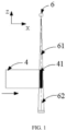
- a thin film or an adhesive layer of the lithium battery needs to be detected. But a thickness of the thin film or the adhesive layer of the lithium battery is small. As shown in FIG.
- a black region represented by 41 in the figure is the film or the adhesive layer mentioned above
- an axis parallel to the main beam surface 61 is defined as the Z axis
- an axis parallel to an advancing direction of the detected object 4 is defined as the X axis
- a Y axis is defined to be perpendicular to both of the X axis and the Z axis.
- An imaging region 62 constituted by rays emitted by a ray machine 6 is approximately of a cone shaped.
- the inventors found that when a detected layer (a detection surface parallel to the main beam surface) of the film or the adhesive layer is deviated in the Z direction or the Y direction, due to the influence of the shape of the imaging region, there may be situation that the detected layer is deviated out of the imaging region, and when the detected layer is deviated out of the imaging region, a portion of the detected layer may not be detected, resulting in a problem of detection inaccuracy.
- FIG. 2 to FIG. 13 , FIG. 15 and FIG. 16 the specific implementation manners of the attitude adjustment structure in the embodiments of the present disclosure are shown.
- the attitude adjustment structure in the embodiments of the present disclosure includes a base body 1, a first adjustment assembly 2, and a second adjustment assembly 3.
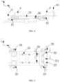
- the detected object 4 is placed on the base body 1, and the first adjustment assembly 2 is used to adjust a deviate of the detected object 4 around the Y direction on the base body 1, i.e., a direction indicated by a two-way arrow in FIG. 3 .
- the base body 1 in the embodiments of the present disclosure is arranged in the X direction.
- a plurality of detected objects 4 may be placed on the base body 1 at intervals.
- the base body 1 may be a common production conveying line, for example, a production console, a placement assembly line, and the like.
- the base body 1 is designed to be a supporting frame of an assembly line style, including two frame bodies 12 arranged opposite to each other, and the first adjustment assembly 2 is arranged between the two frame bodies 12.
- a cross-section shape of the two frame bodies 12 is L-shaped, and therefore it includes a horizontal supporting arm and a vertical supporting arm.
- a supporting rail 13 is mounted on the horizontal supporting arm, and an upper surface of the supporting rail 13 is configured to be the bearing surface 11.
- the detected object 4 spans the two supporting rails 13 and is supported by the bearing surfaces 11 of the support rails 13 to achieve a function of placing the detected object 4.
- the detected object 4 in the embodiments of the present disclosure may be a lithium battery.
- the lithium battery When the lithium battery is placed on the bearing surface 11, it is necessary to ensure that a plane where a thickness of an adhesive layer or a film layer thereof is located is substantially arranged to face the ray machine of the imaging system.
- FIG. 4 to FIG. 10 show the specific structure of the first adjustment assembly 2.
- the first adjustment assembly 2 includes a rack 21, and the rack 21 is movably arranged on the base body 1 and is slidable relative to the base body 1.
- the rack 21 is a square frame body structure
- sliding blocks 51 are respectively mounted on two frame edges thereof arranged opposite to each other
- a sliding rail 52 is mounted on an inner side of a vertical wall of the frame body 12 of the base body 1
- the sliding blocks 51 are slidably arranged on the sliding rail 52, so that the rack 21 moves relative to the base body 1 in the X direction under a driving of an external force.
- the sliding blocks 52 may also be mounted on the rack 21, and the sliding rail 51 may be mounted on the base body 1.
- driving of an external force may be a manpower driving, an electric driving, a hydraulic driving, a pneumatic driving and the like.
- the first adjustment assembly 2 further includes a rotating member.
- the rotating member is rotatably arranged on the rack 21 with the Y axis as a rotation axis and used to drive the detected object to deviate around the Y direction on the bearing surface under a driving of an external force, and drive the detected object to move in the X direction under a leading of the rack 21.
- the rotating member in the embodiments of the present disclosure is in a form of a combination of a turning lever and a turning head, and the specific structure is as follows:
- a turning lever 22 is mounted on the rack 21, and the turning lever 22 is rotatably arranged on the rack 21 with the Y axis as a rotation axis.
- a rotating shaft 211 is arranged in the Y direction, and the rotating shaft 211 is fixed on the rack 21.
- the rack 21 has a border transversely arranged between the frame bodies 12, and the rotating shaft 211 is arranged at a center of an upper end surface of the border described above, and the setting at the center may ensure that lengths of rotating arms of the turning lever 22 arranged on the rotating shaft 211 are consistent, thereby facilitating a subsequent adjustment of a deviate angle.
- the turning lever 22 may be rotatably mounted on the rotating shaft 211
- the turning lever 22 is arranged on an adapter block 25, and two turning levers 22 are respectively arranged on the adapter block 23 opposite to each other.
- An mounting hole is processed at a middle position of the adapter block 25, and the mounting hole is embedded with a bearing and a retaining ring 27 for restricting the bearing from coming out of the mounting hole.
- the rotating shaft 211 is matched and mounted in the bearing, so as to achieve a rotation of the adapter block 25 around the rotating shaft 211 and lead a rotation of the turning lever 22 around the Y direction.
- the first adjustment assembly 2 in the embodiments of the present disclosure further includes a turning head 23, and the turning head 23 is arranged on the turning lever 22.
- the turning head 23 may abut against the detected object 4 under a driving of the turning lever 22, so as to drive the detected object 4 to deviate around the Y direction on the bearing surface 11 and to drive the detected object to move in the X direction on the bearing surface.
- the turning heads 23 are respectively mounted at ends of the two turning levers 22.
- the turning heads 23 protrude from the bearing surface 11, and may abut against an end face of the detected object 4 in a direction of a backward movement when the rack 21 moves.
- an abutment position of the turning head 23 deviates from a central position of the end surface.
- the process of driving the detected object 4 on the bearing surface 11 to deviate around the Y direction by the turning head 23 is as follows.
- the adapter block 25 rotates, and leads the turning lever 22 to rotate, so that the turning head 23 on the turning lever 22 acts on the detected object 4 and the turning head 23 pushes the detected object 4 to rotate, thereby achieving a correction of the deviate of the detected object 4.
- the detection method of whether the detected object 4 has deviated in the Y direction may be detected by a position sensor to detect spatial position coordinates of a current detected object 4 to determine whether it has deviated. It may also be determined by a detection result of a previous detected object 4. If the detection result of the previous detected object 4 is an occurrence of deviating, then a deviating adjustment needs to be performed on the current detected object 4.
- the turning head 23 may push the detected object 4 to move in the X direction to enter the next detection step.
- the turning head 23 may only abut against the detected object 4 to drive the detected object 4 to deviate around the Y direction on the bearing surface 11.
- the movement of the detected object 4 in the X direction may be driven by other structures.
- the rotating member may also be a combination of a turntable and a lifting structure.
- the turntable is arranged on the lifting structure. Under a leading of the lifting structure, the turntable 21 may move up and down in the Y direction. When the turntable 21 rises, it may bear the detected object 4 on the base body 1.
- the turntable is rotatably arranged on the lifting structure. Under a driving of an external force, the turntable bearing the detected object 4 may rotate around the Y direction.
- the lifting structure is fixed on the rack 1, and under a leading of the rack 1, the turntable may also move in the X direction, so as to achieve an adjustment of the deviate of the detected object in the Y direction.
- the first adjustment assembly 2 further includes a first driving unit 26, where the first driving unit 26 is used to push a rotation of the adapter block 25, and specifically, the first driving unit 26 has a pushing rod 261 that may move toward or away from the adapter block 25, and a first motor 262.
- An end of the pushing rod 261 is movably connected to the adapter block 25, and the other end thereof is connected to the first motor 262.
- the push rod 261 needs to be connected to an end of the adapter block 25 away from the rotating shaft 211 to form a rotational moment during pushing.
- the first motor 262 is arranged on the rack 21, and a rotation of the first motor 262 leads the pushing rod 261 to rotate.
- a thread sleeve 251 is mounted on an end face of the adapter block 251 towards the pushing rod 261, and the pushing rod 261 is provided with a threaded section cooperating with the thread sleeve 251.
- the threaded section rotates within the thread sleeve 251 to drive the adapter block 251 to rotate.
- two sets of first driving units 26 are provided in the embodiments of the present disclosure, and they are arranged symmetrically with respect to the rotating shaft 211.
- a pushing rod 261 of one first driving unit 26 moves towards the turning lever 26, and the pushing rod 261 of the other first driving unit 26 moves away from the turning rod 26.
- the quantity of the first driving unit 26 may be one set.
- the pushing rod 261 and the adapter block 25 may be adjusted through a cooperation of a telescopic rod with a universal joint to achieve a reciprocating swing of the turning lever 22 around the Y direction.
- the quantity of the turning heads 23 mounted on the turning lever 22 may be multiple, so as to adjust a position of turning.
- the rack 21 when the rack 21 moves, it has a function of pushing the detected objects 4 to move in the X direction through the turning head 23, and the detected objects 4 are arranged on the base body 1 at intervals.
- the rack 21 drives a previous detected object 4 to move to the next process in the X direction
- the rack 21 may be driven back, and the turning head 23 is allowed to abut against the end face of the detected object 4 in a direction of a backward movement again, so as to push the detected object 4 to move in the X direction.
- the turning head 23 is also needed to be rotatably arranged on the turning lever 22, rotatable around an axis direction of the turning lever 22, and configured as an eccentric structure.
- the turning head 23 has a first position protruding from the bearing surface 11 under a driving of an eccentric force and a second position turned below the bearing surface under an action of an external force.
- the turning head 23 at the first position is used to push the detected object to move in the X direction.
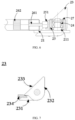
- the turning head 23 has: a pushing surface 232 configured to abut against the detected object; a guiding surface 233 provided at an angle to the pushing surface 232 and configured to receive an external force.
- the turning head 23 in the present embodiment is in a shape of a right triangle, the pushing surface 232 described above corresponds to a plane where the right angle sides are located, and the guiding surface 233 corresponds to a plane where the beveled side is located.
- a limiting structure 234 is used to limit a rotation of the turning head 23 when the turning head 23 moves to the first position, wherein when the rack 21 moves in a negative direction in the X axis, the guiding surface 233 hits on the detected object to drive the turning head 23 to move to the second position.
- the limiting structure 234 is a limiting block arranged at the guiding surface 233 and protruding from the guiding surface 233.
- the turning head 23 is led under an action of an eccentric force to rotate counterclockwise on the turning lever 22, when rotating to a preset position, the limiting structure 234 is blocked by a limiting portion on the rack 21, and may not continue to rotate, the position here is the first position, and in the first position, the turning head may not rotate counterclockwise.
- the pushing surface 232 abuts against the detected object 4, and a reverse force exerted by the detected object 4 will not drive the turning head 23 to rotate counterclockwise, so that the turning head 23 may push the detected object 4 to move in the X direction.
- the guiding surface 233 will preferentially hit a detected object 4 at the rear, and under an action of the impact force, the turning head 23 will rotate clockwise.
- the turning head 23 is gradually pressed down by the detected object 4 to a lower portion of the bearing surface 11, the position here is the second position, until having slid over the detected object 4, the turning head 23 returns to the first position again under an action of an eccentric force, the pushing surface 232 is again located on the end face of the detected object 4 in a direction of a backward movement, at this time, the rack 21 is driven to move forward in the X direction, and the turning head 23 continues to push the detected object 4 to move in the X direction to enter the next process.
- the above steps are repeated to achieve conveying of the detected object 4.
- a balancing block is provided on the turning head 23 to adjust an eccentric distance of the turning head 23, so that the pushing surface 232 is parallel to the YZ plane at the first position.
- a parallel setting of the pushing surface 232 and the YZ plane may ensure that when the pushing surface 232 pushes the detected object 4, the pushing surface 232 fits on the detected object 4, thereby ensuring a smooth movement of the detected object 4 on the bearing surface 11.
- a material incoming manner of the detected object 4 is that one detected object is conveyed from a material incoming point of the base body 1 every certain time interval.
- the distance between the material incoming point of the detected object 4 and the imaging region is relatively long, as a result, a travel of the rack 21 moving forward or backward between the material incoming point and the imaging region is relatively long, and this increases a conveying time of the detected object 4.
- a turning head 23 is rotatably arranged at an end of the rack 21 away from the first adjustment assembly 2, and the turning head 23 and the turning head in the first assembly 2 are arranged at an interval in the X direction.
- a distance of the interval described above may be half of a distance from the material incoming point to the imaging region.
- two detected objects 4 may be led to move forward at one time, so that the conveying efficiency of the detected object 4 is improved.
- a plurality of turning heads 23 may be adaptively arranged in the X direction, so as to improve the conveying efficiency of the detected objects 4.
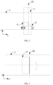
- FIG. 2 schematically shows a process of adjusting a deviate of the detected object 4 in the Z direction by the second adjustment assembly 3. An adjustment direction is indicated by a two-way arrow in FIG. 2 .
- FIG. 11 to FIG. 13 schematically illustrates the specific structure of the second adjustment assembly 3.
- the second adjustment assembly 3 is arranged on the base body 1.
- the second adjustment assembly includes: a supporting plate 31, rotatably arranged on the base body 1 with the Z axis as a rotation axis and configured to bear the detected object thereon.
- the supporting plate 31 is a supporting beam structure.
- Hinge seats 33 are respectively arranged on the horizontal supporting arms of two frame bodies 12 of the base body 1 correspondingly, so as to achieve a connection with the supporting plate 31.
- an end of the supporting plate 31 close to the first adjustment assembly 2 is hinged on the base body 1. Moreover, in order to ensure that the detected object 4 moves smoothly from the first adjustment assembly 2 to the second adjustment assembly 3, it may be controlled that in the Y direction, a height of the bearing surface 11 is higher than an upper surface of the supporting plate 31.
- the second adjustment assembly 3 further includes: a second driving unit 32, wherein the second driving unit 32 is arranged on the base body 1 and disposed below the supporting plate 31 away from a hinged end to drive the supporting plate 31 to rotate.
- the second drive unit 32 includes: a second motor 321, arranged on the base body 1; and a lifting rod 322, arranged on a motor shaft of the second motor 321, and an end of the lifting rod is connected to the supporting plate 31.
- the second motor 321 leads the lifting rod 322 to rotate through a shaft coupling.
- An end of the lifting rod 322 is connected to a joint 34 arranged on a lower end surface of the supporting plate 31, and the lifting rod 322 may be screwed on the joint 34.
- a reversible rotation of the second motor 321 a reversible rotation of the lifting rod may be achieved, so that the supporting plate 322 is led to rotate clockwise or counterclockwise around a hinge axis.
- the driving form of the second driving unit 32 may be various, and in some embodiments, common pushing rod motor driving, cylinder telescopic driving and the like are used.
- a movement process of the detected object 4 in the attitude adjustment structure of the present disclosure is schematically illustrated.
- the detected object 4 placed on the bearing surface 11 is led by the turning head 23 under an action of the turning lever 22 of the first adjustment assembly 2 to complete a deviating adjustment in the Y direction.
- the detected object 4 is led by the rack 21 under a push of the turning head 23 to complete a movement in the X direction and enters the second adjustment assembly 3.
- the detected object 4 completes a deviating adjustment in the Z direction.
- the detected object 4 completes an attitude adjustment, and enters the next step for a radiation imaging process.
- structures such as the supporting plate 31 in the second adjustment assembly 3 in the present embodiment are preferably made of carbon fiber materials.
- the supporting plate 31 affected by weight changes of the detected objects 4, degrees of bending deformation of the supporting plate 31 are different, and a rotation angle of the supporting plate 31 needs to be adjusted every time. This increases the operation processes.
- an implementation manner of another second adjusting assembly 3 is provided in the present disclosure.
- two sets of second adjustment assemblies 3 shown in FIG. 11 to FIG. 13 are used in this solution.
- the two sets of second adjustment assemblies 3 are arranged at intervals.
- imaging regions of the radiation imaging are just within interval regions arranged at intervals.
- Such setting ensures that no attenuation of rays will occur when the supporting plate 31 is made of a metal having a better rigidity.
- a conveying device is further provided in the embodiments of the present disclosure.
- the conveying device includes the attitude adjustment structure in the above embodiments.
- the conveying device may at least include a first section and a second section arranged at a front end and a rear end of the attitude adjustment structure.
- the first section of the conveying device is responsible for conveying an object 4 to be detected to the bearing surface 11 of the base body 1, and the second section thereof is responsible for conveying the detected object 4 on the second adjustment assembly 3 to a subsequent process after a radiation imaging process is completed.
- Belt conveyors, roller conveyors, etc. may be used as the first section of the conveying device and the second section of the conveying device.
- a radiation imaging system is further provided in the embodiments of the present disclosure, specifically a CT imaging system.
- the present device is also applicable to a DR imaging system.
- the radiation imaging system includes the conveying device described above and a scanning device.
- the scanning device is arranged on two sides of the second adjustment assembly 3. After the detected object 4 is adjusted to a preset detection position by the attitude adjustment structure, a ray machine in the scanning device emits X-rays towards the detected object 4, the X-rays pass through the detected object 4 and are received by a detector located at the other end of the detected object 4 to complete scanning and imaging. An image reconstruction is completed by processing scanned data, and a reconstructed image is displayed to an inspector for a judgment of a detection result of the detected object 4.
- each block in a flowchart or block diagram may represent a module, a program segment, or a portion of codes, and the above module, program segment, or portion of codes includes one or more executable instructions for implementing specified logical functions.
- functions noted in the blocks may occur in a sequence different from the sequence noted in the figures. For example, two blocks shown in a successive manner may be actually executed in a substantially concurrent manner, or they may sometimes be executed in a reverse sequence, depending on functions involved.
- each block in a block diagram or flowchart, and a combination of blocks in the block diagram or flowchart may be implemented by a dedicated hardware-based system that performs specified functions or operations, or may be implemented by a combination of dedicated hardware and computer instructions.
Landscapes
- Health & Medical Sciences (AREA)
- General Physics & Mathematics (AREA)
- General Health & Medical Sciences (AREA)
- Pathology (AREA)
- Immunology (AREA)
- Life Sciences & Earth Sciences (AREA)
- Physics & Mathematics (AREA)
- Chemical & Material Sciences (AREA)
- Biochemistry (AREA)
- Analytical Chemistry (AREA)
- Engineering & Computer Science (AREA)
- Nuclear Medicine, Radiotherapy & Molecular Imaging (AREA)
- Theoretical Computer Science (AREA)
- Radiology & Medical Imaging (AREA)
- Pulmonology (AREA)
- Mechanical Engineering (AREA)
- Analysing Materials By The Use Of Radiation (AREA)
Abstract
Description
- The present disclosure relates to a field of detection apparatus technology, and in particular, to an attitude adjustment structure, a conveying device, and a radiation imaging system.
- Radiation imaging is a technology to observe an inside of an object using rays. Such technology may obtain information such as the structure and density of the inside of the object without destroying the object, and is currently widely used in scenarios such as chest X-rays in hospitals and security inspections in stations and airports. However, when a detected object is a thin film or an adhesive layer, in order to ensure the accuracy of detection, it is necessary that a main beam plane of a light beam generated by a ray machine in a radiation imaging system be parallel to a detected layer of the detected object.
- With this regard, according to the present disclosure, there is provided an attitude adjustment structure, a conveying device, and a radiation imaging system.
- According to an aspect of the present disclosure, there is provided an attitude adjustment structure, including: a base body, arranged in an X direction, the base body having a bearing surface, and the bearing surface being configured to place a detected object; a first adjustment assembly, arranged on the base body and configured to drive the detected object to deviate around a Y direction on the bearing surface and drive the detected object to move in the X direction; and at least one second adjustment assembly, arranged on the base body and configured to drive the detected object to rotate around a Z direction.
- According to an embodiment of the present disclosure, the first adjustment assembly includes: a rack, slidable in the X direction relative to the base body; and a rotating member, rotatably arranged on the rack with the Y axis as a rotation axis and configured to drive the detected object to deviate around the Y direction on the bearing surface under a driving of an external force, and drive the detected object to move in the X direction under a driving of the rack.
- According to an embodiment of the present disclosure, the rotating member includes: a turning lever, rotatably arranged on the rack with the Y axis as a rotation axis; and a turning head, arranged on the turning lever and allowed to abut against the detected object under a driving of the driving rod.
- According to an embodiment of the present disclosure, the rack is provided with a rotating shaft protruding in the Y direction, and the first adjustment assembly further includes: an adapter block rotatably arranged on the rotating shaft, the driving lever being fixed on the adapter block.
- According to an embodiment of the present disclosure, the first adjustment assembly further includes: at least one first driving unit, arranged on the rack, the first driving unit having a pushing rod movable toward or away from the adapter block, wherein, the pushing rod is movably connected to an end of the adapter block away from the rotating shaft.
- According to an embodiment of the present disclosure, the first driving unit further includes: a first motor, arranged on the rack, an end of the pushing rod is connected to a motor shaft of the first motor; wherein an end of the pushing rod close to the adapter block is provided with a threaded section, and the adapter block is provided with a thread sleeve matched with the threaded section.
- According to an embodiment of the present disclosure, at least one of the turning head is rotatably arranged on the turning lever and is configured as an eccentric structure, wherein, the turning head has a first position protruding from the bearing surface under a driving of an eccentric force and a second position turned below the bearing surface under an action of an external force; and when the rack moves in the X direction, the turning head at the first position is configured to push the detected object to move in the X direction.
- According to an embodiment of the present disclosure, the turning head has: a pushing surface configured to abut against the detected object; a guiding surface, arranged at an angle to the pushing surface and configured to receive an external force; a limiting structure, configured to limit a rotation of the turning heat when the turning head moves to the first position; wherein, when the rack moves in a negative direction of the X axis, the guiding surface hits the detected object to drive the turning head to move to the second position.
- According to an embodiment of the present disclosure, the attitude adjustment structure further includes: a balancing weight, arranged on the turning head and configured to adjust an eccentric distance of the turning head, so that the pushing surface is parallel to a YZ plane at the first position.
- According to an embodiment of the present disclosure, in the X direction, a plurality of the turning heads are rotatably arranged on the rack, and the plurality of the turning heads are arranged at intervals, so as to push the detected object on the base body to move toward a detection region.
- According to an embodiment of the present disclosure, a sliding rail-sliding block structure is arranged between the rack and the base body.
- According to an embodiment of the present disclosure, the detected object is conveyed to the second adjustment assembly under a driving of the first adjustment assembly, and wherein the second adjustment assembly includes: a supporting plate, rotatably arranged on the base body with the Z axis as a rotation axis and configured to bear the detected object thereon.
- According to an embodiment of the present disclosure, an end of the supporting plate close to the first adjustment assembly is hinged on the base body, and the second adjustment assembly further includes: a second driving unit, arranged on the base body and disposed below the supporting plate away from a hinged end to drive the supporting plate to rotate.
- According to an embodiment of the present disclosure, the second driving unit includes: a second motor, arranged on the base body; and a lifting rod, arranged on a motor shaft of the second motor with an end of the lifting rod being connected to the supporting plate.
- According to an embodiment of the present disclosure, two second adjustment assemblies are arranged in the X direction at an interval, and a ray for detecting the detected object passes through a middle of the interval.
- According to another aspect of the present disclosure, there is provided a conveying device, including: the attitude adjustment structure according to any one of the above descriptions.
- According to another aspect of the present disclosure, there is provided a radiation imaging system, including: the conveying device described above, and a scanning device, arranged on two sides of a second adjustment assembly and configured to scan a detected object placed on the second adjustment assembly.
- The attitude adjustment structure in the present disclosure includes: a base body, arranged in an X direction, the base body having a bearing surface, and the bearing surface being configured to place a detected object; a first adjustment assembly, arranged on the base body and configured to drive the detected object to deviate around a Y direction on the bearing surface and drive the detected object to move in the X direction; and at least one second adjustment assembly, arranged on the base body and configured to drive the detected object to rotate around a Z direction. The first adjustment assembly in the present disclosure achieves a deviating adjustment of the detected object in the Y direction, and may push the detected object to move in the X direction; and the second adjustment assembly achieves a deviating adjustment of the detected object in the Z direction. Under actions of the first adjustment assembly and the second adjustment assembly, the detected object may be adjusted to a state suitable for a detection. When the attitude adjustment structure in the present disclosure is used in the radiation imaging system for a film or an adhesive layer detection as introduced in the background technology, by a deviating adjustment of the detected object, it may be ensured that the main beam surface of the light beam generated by the ray machine is parallel to the detected layer surface of the detected object, so that the accuracy of detection is guaranteed.
- The above and other objectives, features and advantages of the present disclosure will be more clearly described through the following description of the embodiments of the present disclosure with reference to the accompanying drawings, in which:
-
FIG. 1 schematically shows a simple diagram of a principle of a radiation imaging according to an embodiment of the present disclosure; -
FIG. 2 schematically shows a simple diagram of an adjustment manner of a second adjustment assembly according to an embodiment of the present disclosure; -
FIG. 3 schematically shows a simple diagram of an adjustment manner of a first adjustment assembly according to an embodiment of the present disclosure; -
FIG. 4 schematically shows a front view of a first adjustment assembly according to an embodiment of the present disclosure; -
FIG. 5 schematically shows a top view of a first adjustment assembly according to an embodiment of the present disclosure; -
FIG. 6 schematically shows a cross-sectional view at A-A inFIG. 5 ; -
FIG. 7 schematically shows a cross-sectional view at B-B inFIG. 5 ; -
FIG. 8 schematically shows a schematic structural diagram of a turning head according to an embodiment of the present disclosure; -
FIG. 9 schematically shows a cross-sectional view at C-C inFIG. 5 ; -
FIG. 10 schematically shows a side view of a first adjustment assembly according to an embodiment of the present disclosure; -
FIG. 11 schematically shows a top view of a second adjustment assembly according to an embodiment of the present disclosure; -
FIG. 12 schematically shows a front view of a second adjustment assembly according to an embodiment of the present disclosure; -
FIG. 13 schematically shows a cross-sectional view at D-D inFIG. 12 ; -
Fig. 14 schematically shows a top view of another implementation manner of a second adjustment assembly according to an embodiment of the present disclosure; -
FIG. 15 schematically shows a front view of an attitude adjustment structure according to an embodiment of the present disclosure; and -
FIG. 16 schematically shows a top view of an attitude adjustment structure according to an embodiment of the present disclosure. -
- 1. base body; 11-bearing surface; 12-frame body; 13-supporting rail;
- 2. first adjustment assembly; 21-rack; 22-turning lever; 23-turning head; 24-bearing; 25-adapter block; 26-first driving unit; 27-retaining ring; 231-balancing weight; 232-pushing surface; 233-guiding surface; 234-limiting structure; 211-rotating shaft; 251-thread sleeve; 261-pushing rod; 262-first motor;
- 3. second adjustment assembly; 31-supporting plate; 32-second driving unit; 321-second motor; 322-lifting rod; 33-hinge seat; 34-joint;
- 4. detected object; 41-detected layer;
- 5. sliding rail and sliding block structure; 51-sliding block; 52-sliding rail;
- 6.ray machine; 61-main beam surface; 62-scanning region;
- 7. scanning device.
- Hereinafter, the embodiments of the present disclosure will be described with reference to the accompanying drawings. However, it should be understood that these descriptions are exemplary only, and are not intended to limit the scope of the present disclosure. In the following detailed description, for the purpose of explanation, numerous specific details are set forth in order to provide a thorough understanding of the embodiments of the present disclosure. It may be evident, however, that one or more embodiments may be implemented without these specific details. Additionally, in the following description, descriptions of commonly known structures and technologies are omitted to avoid unnecessarily obscuring the concept of the present disclosure.
- The terms used herein are for the purpose of describing particular embodiments only, and are not intended to limit the present disclosure. The terms such as "comprise"/"include" and "contain" used herein indicate a presence of the feature, step, operation and/or component, but do not exclude a presence or an addition of one or more other features, steps, operations or components.
- When an expression such as "at least one of A, B, or C" is used, it should generally be interpreted according to the meaning commonly understood by those skilled in the art (for example, an expression "a system having at least one of A, B, or C" should include, but not be limited to, a system only having A, a system only having B, a system only having C, a system having A and B, a system having A and C, a system having B and C, and/or a system having A, B and C). The terms "first" and "second" are only used for descriptive purposes, and may not be understood as indicating or implying a relative importance or implicitly specifying a quantity of an indicated technical feature. Therefore, a feature defined as "first" or "second" may explicitly or implicitly include one or more of said features.
- A detailed background technology may include other technical problems other than the technical problems to be solved by independent claims.
- According to an embodiment of the present disclosure, there is provided an attitude adjustment structure including: a base body, arranged in an X direction, the base body having a bearing surface, and the bearing surface being configured to place a detected object; and a first adjustment assembly, arranged below the base body, wherein the first adjustment assembly includes: a rack, slidable in the X direction relative to the base body; a turning lever, rotatably arranged on the rack with the Y axis as a rotation axis; and a turning head, arranged on the turning lever and allowed to abut against the detected object under a driving of the driving rod to drive the detected object to deviate around a Y direction on the bearing surface, and/or drive the detected object to move in the X direction on the bearing surface.
- The attitude adjustment structure of the present disclosure may be used to adjust a movement attitude of an object conveyed on a production line; it may also be used in the field of radiation detection to adjust a detected object to a preset detection position. In the application of the field of radiation detection, the attitude adjustment structure in the present disclosure needs to be used in at least the following scenarios. The scenarios are described as follows.
- It may be understood that in the field of radiation detection, the radiation imaging technology may perform an imaging on a damage of an internal portion of an object to facilitate judgment by an inspector. In the detected objects, there are regions to be detected having a small detection dimension. For example, in a detection process of a lithium battery, a thin film or an adhesive layer of the lithium battery needs to be detected. But a thickness of the thin film or the adhesive layer of the lithium battery is small. As shown in
FIG. 1 , a black region represented by 41 in the figure is the film or the adhesive layer mentioned above, an axis parallel to themain beam surface 61 is defined as the Z axis, an axis parallel to an advancing direction of the detectedobject 4 is defined as the X axis, and a Y axis is defined to be perpendicular to both of the X axis and the Z axis. Animaging region 62 constituted by rays emitted by aray machine 6 is approximately of a cone shaped. In the actual detection, the inventors found that when a detected layer (a detection surface parallel to the main beam surface) of the film or the adhesive layer is deviated in the Z direction or the Y direction, due to the influence of the shape of the imaging region, there may be situation that the detected layer is deviated out of the imaging region, and when the detected layer is deviated out of the imaging region, a portion of the detected layer may not be detected, resulting in a problem of detection inaccuracy. - Based on the above problems, as shown in
FIG. 2 to FIG. 13 ,FIG. 15 and FIG. 16 , the specific implementation manners of the attitude adjustment structure in the embodiments of the present disclosure are shown. - Referring to
FIG. 3 , the attitude adjustment structure in the embodiments of the present disclosure includes abase body 1, afirst adjustment assembly 2, and asecond adjustment assembly 3. The detectedobject 4 is placed on thebase body 1, and thefirst adjustment assembly 2 is used to adjust a deviate of the detectedobject 4 around the Y direction on thebase body 1, i.e., a direction indicated by a two-way arrow inFIG. 3 . - Referring to
FIG. 4 , thebase body 1 in the embodiments of the present disclosure is arranged in the X direction. A plurality of detectedobjects 4 may be placed on thebase body 1 at intervals. Thebase body 1 may be a common production conveying line, for example, a production console, a placement assembly line, and the like. - As shown in
FIG. 10 , thebase body 1 is designed to be a supporting frame of an assembly line style, including twoframe bodies 12 arranged opposite to each other, and thefirst adjustment assembly 2 is arranged between the twoframe bodies 12. A cross-section shape of the twoframe bodies 12 is L-shaped, and therefore it includes a horizontal supporting arm and a vertical supporting arm. A supportingrail 13 is mounted on the horizontal supporting arm, and an upper surface of the supportingrail 13 is configured to be the bearingsurface 11. The detectedobject 4 spans the two supportingrails 13 and is supported by the bearing surfaces 11 of the support rails 13 to achieve a function of placing the detectedobject 4. - The detected
object 4 in the embodiments of the present disclosure may be a lithium battery. When the lithium battery is placed on the bearingsurface 11, it is necessary to ensure that a plane where a thickness of an adhesive layer or a film layer thereof is located is substantially arranged to face the ray machine of the imaging system. -
FIG. 4 to FIG. 10 show the specific structure of thefirst adjustment assembly 2. - Referring to
FIG. 10 , thefirst adjustment assembly 2 includes arack 21, and therack 21 is movably arranged on thebase body 1 and is slidable relative to thebase body 1. As shown inFIG. 10 , therack 21 is a square frame body structure, slidingblocks 51 are respectively mounted on two frame edges thereof arranged opposite to each other, a slidingrail 52 is mounted on an inner side of a vertical wall of theframe body 12 of thebase body 1, and the slidingblocks 51 are slidably arranged on the slidingrail 52, so that therack 21 moves relative to thebase body 1 in the X direction under a driving of an external force. - It may be understood that, in some implementation manners, the sliding
blocks 52 may also be mounted on therack 21, and the slidingrail 51 may be mounted on thebase body 1. - It may be understood that driving of an external force may be a manpower driving, an electric driving, a hydraulic driving, a pneumatic driving and the like.
- In the embodiment of the present disclosure, the
first adjustment assembly 2 further includes a rotating member. The rotating member is rotatably arranged on therack 21 with the Y axis as a rotation axis and used to drive the detected object to deviate around the Y direction on the bearing surface under a driving of an external force, and drive the detected object to move in the X direction under a leading of therack 21. - It may be understood that there may be various structures and forms of the rotating member. The rotating member in the embodiments of the present disclosure is in a form of a combination of a turning lever and a turning head, and the specific structure is as follows:
- As shown in
FIG. 5 , a turninglever 22 is mounted on therack 21, and the turninglever 22 is rotatably arranged on therack 21 with the Y axis as a rotation axis. Referring toFIG. 9 , on therack 21, arotating shaft 211 is arranged in the Y direction, and therotating shaft 211 is fixed on therack 21. Further, therack 21 has a border transversely arranged between theframe bodies 12, and therotating shaft 211 is arranged at a center of an upper end surface of the border described above, and the setting at the center may ensure that lengths of rotating arms of the turninglever 22 arranged on therotating shaft 211 are consistent, thereby facilitating a subsequent adjustment of a deviate angle. - It may be understood that, in order that the turning
lever 22 may be rotatably mounted on therotating shaft 211, in the embodiments of the present disclosure, the turninglever 22 is arranged on anadapter block 25, and two turninglevers 22 are respectively arranged on theadapter block 23 opposite to each other. An mounting hole is processed at a middle position of theadapter block 25, and the mounting hole is embedded with a bearing and a retainingring 27 for restricting the bearing from coming out of the mounting hole. Therotating shaft 211 is matched and mounted in the bearing, so as to achieve a rotation of theadapter block 25 around therotating shaft 211 and lead a rotation of the turninglever 22 around the Y direction. - As shown in
FIG. 4 , thefirst adjustment assembly 2 in the embodiments of the present disclosure further includes a turninghead 23, and the turninghead 23 is arranged on the turninglever 22. The turninghead 23 may abut against the detectedobject 4 under a driving of the turninglever 22, so as to drive the detectedobject 4 to deviate around the Y direction on the bearingsurface 11 and to drive the detected object to move in the X direction on the bearing surface. - In the embodiments of the present disclosure, the turning heads 23 are respectively mounted at ends of the two turning
levers 22. The turning heads 23 protrude from the bearingsurface 11, and may abut against an end face of the detectedobject 4 in a direction of a backward movement when therack 21 moves. Moreover, in order to achieve a deviate of the detectedobject 4, an abutment position of the turninghead 23 deviates from a central position of the end surface. - It may be understood that the process of driving the detected
object 4 on the bearingsurface 11 to deviate around the Y direction by the turninghead 23 is as follows. When therack 21 moves to the detectedobject 4 driven under a driving of external force, if a deviate of the detected object in the Y direction is deviated, theadapter block 25 rotates, and leads the turninglever 22 to rotate, so that the turninghead 23 on the turninglever 22 acts on the detectedobject 4 and the turninghead 23 pushes the detectedobject 4 to rotate, thereby achieving a correction of the deviate of the detectedobject 4. The detection method of whether the detectedobject 4 has deviated in the Y direction may be detected by a position sensor to detect spatial position coordinates of a current detectedobject 4 to determine whether it has deviated. It may also be determined by a detection result of a previous detectedobject 4. If the detection result of the previous detectedobject 4 is an occurrence of deviating, then a deviating adjustment needs to be performed on the current detectedobject 4. - It may be understood that after the deviate correction of the detected
object 4 is completed, when therack 21 continues to move in the X direction, the turninghead 23 may push the detectedobject 4 to move in the X direction to enter the next detection step. - It may be understood that, in some embodiments, under a driving of the turning
lever 22, the turninghead 23 may only abut against the detectedobject 4 to drive the detectedobject 4 to deviate around the Y direction on the bearingsurface 11. The movement of the detectedobject 4 in the X direction may be driven by other structures. - It may be understood that, in some embodiments, the rotating member may also be a combination of a turntable and a lifting structure. Specifically, the turntable is arranged on the lifting structure. Under a leading of the lifting structure, the
turntable 21 may move up and down in the Y direction. When theturntable 21 rises, it may bear the detectedobject 4 on thebase body 1. At the same time, the turntable is rotatably arranged on the lifting structure. Under a driving of an external force, the turntable bearing the detectedobject 4 may rotate around the Y direction. Further, the lifting structure is fixed on therack 1, and under a leading of therack 1, the turntable may also move in the X direction, so as to achieve an adjustment of the deviate of the detected object in the Y direction. - In the embodiments of the present disclosure, the
first adjustment assembly 2 further includes afirst driving unit 26, where thefirst driving unit 26 is used to push a rotation of theadapter block 25, and specifically, thefirst driving unit 26 has a pushingrod 261 that may move toward or away from theadapter block 25, and afirst motor 262. An end of the pushingrod 261 is movably connected to theadapter block 25, and the other end thereof is connected to thefirst motor 262. In order to ensure that the pushingrod 261 may push theadapter block 25 to rotate around therotating shaft 211, thepush rod 261 needs to be connected to an end of theadapter block 25 away from therotating shaft 211 to form a rotational moment during pushing. - Referring to
FIG. 6 , thefirst motor 262 is arranged on therack 21, and a rotation of thefirst motor 262 leads the pushingrod 261 to rotate. Athread sleeve 251 is mounted on an end face of theadapter block 251 towards the pushingrod 261, and the pushingrod 261 is provided with a threaded section cooperating with thethread sleeve 251. When the pushingrod 261 rotates, the threaded section rotates within thethread sleeve 251 to drive theadapter block 251 to rotate. - It may be understood that two sets of
first driving units 26 are provided in the embodiments of the present disclosure, and they are arranged symmetrically with respect to therotating shaft 211. When the two sets offirst driving units 26 drive the turninglever 26 to move, a pushingrod 261 of onefirst driving unit 26 moves towards the turninglever 26, and the pushingrod 261 of the otherfirst driving unit 26 moves away from the turningrod 26. - It may be understood that in some other embodiments, the quantity of the
first driving unit 26 may be one set. When one set of thefirst driving unit 26 is provided, the pushingrod 261 and theadapter block 25 may be adjusted through a cooperation of a telescopic rod with a universal joint to achieve a reciprocating swing of the turninglever 22 around the Y direction. - It may be understood that, in some implementation manners, the quantity of the turning heads 23 mounted on the turning
lever 22 may be multiple, so as to adjust a position of turning. - As described above, in the embodiments of the present disclosure, when the
rack 21 moves, it has a function of pushing the detectedobjects 4 to move in the X direction through the turninghead 23, and the detectedobjects 4 are arranged on thebase body 1 at intervals. When therack 21 drives a previous detectedobject 4 to move to the next process in the X direction, therack 21 may be driven back, and the turninghead 23 is allowed to abut against the end face of the detectedobject 4 in a direction of a backward movement again, so as to push the detectedobject 4 to move in the X direction. In order to achieve a continuous conveying of the detectedobject 4 on thebase body 1 by thefirst adjustment assembly 2, in the embodiments of the present disclosure, the turninghead 23 is also needed to be rotatably arranged on the turninglever 22, rotatable around an axis direction of the turninglever 22, and configured as an eccentric structure. The turninghead 23 has a first position protruding from the bearingsurface 11 under a driving of an eccentric force and a second position turned below the bearing surface under an action of an external force. When therack 21 moves in the X direction, the turninghead 23 at the first position is used to push the detected object to move in the X direction. - As shown in
FIG. 7 andFIG. 8 , the turninghead 23 has: a pushingsurface 232 configured to abut against the detected object; a guidingsurface 233 provided at an angle to the pushingsurface 232 and configured to receive an external force. The turninghead 23 in the present embodiment is in a shape of a right triangle, the pushingsurface 232 described above corresponds to a plane where the right angle sides are located, and the guidingsurface 233 corresponds to a plane where the beveled side is located. A limitingstructure 234 is used to limit a rotation of the turninghead 23 when the turninghead 23 moves to the first position, wherein when therack 21 moves in a negative direction in the X axis, the guidingsurface 233 hits on the detected object to drive the turninghead 23 to move to the second position. Referring toFIG. 7 , the limitingstructure 234 is a limiting block arranged at the guidingsurface 233 and protruding from the guidingsurface 233. With the mounting manner of the turninghead 23 inFIG. 4 , the turninghead 23 is led under an action of an eccentric force to rotate counterclockwise on the turninglever 22, when rotating to a preset position, the limitingstructure 234 is blocked by a limiting portion on therack 21, and may not continue to rotate, the position here is the first position, and in the first position, the turning head may not rotate counterclockwise. When therack 21 advances in the X direction, the pushingsurface 232 abuts against the detectedobject 4, and a reverse force exerted by the detectedobject 4 will not drive the turninghead 23 to rotate counterclockwise, so that the turninghead 23 may push the detectedobject 4 to move in the X direction. When therack 21 moves in the negative direction of X, i.e., when it moves backwards, the guidingsurface 233 will preferentially hit a detectedobject 4 at the rear, and under an action of the impact force, the turninghead 23 will rotate clockwise. In the moving process, the turninghead 23 is gradually pressed down by the detectedobject 4 to a lower portion of the bearingsurface 11, the position here is the second position, until having slid over the detectedobject 4, the turninghead 23 returns to the first position again under an action of an eccentric force, the pushingsurface 232 is again located on the end face of the detectedobject 4 in a direction of a backward movement, at this time, therack 21 is driven to move forward in the X direction, and the turninghead 23 continues to push the detectedobject 4 to move in the X direction to enter the next process. The above steps are repeated to achieve conveying of the detectedobject 4. - As shown in
FIG. 8 , in order to ensure that the center of the turninghead 23 does not coincide with the center of rotation, a balancing block is provided on the turninghead 23 to adjust an eccentric distance of the turninghead 23, so that the pushingsurface 232 is parallel to the YZ plane at the first position. A parallel setting of the pushingsurface 232 and the YZ plane may ensure that when the pushingsurface 232 pushes the detectedobject 4, the pushingsurface 232 fits on the detectedobject 4, thereby ensuring a smooth movement of the detectedobject 4 on the bearingsurface 11. - In the embodiments of the present disclosure, a material incoming manner of the detected
object 4 is that one detected object is conveyed from a material incoming point of thebase body 1 every certain time interval. However, the distance between the material incoming point of the detectedobject 4 and the imaging region is relatively long, as a result, a travel of therack 21 moving forward or backward between the material incoming point and the imaging region is relatively long, and this increases a conveying time of the detectedobject 4. In order to solve the above problem, in the embodiments of the present disclosure, a turninghead 23 is rotatably arranged at an end of therack 21 away from thefirst adjustment assembly 2, and the turninghead 23 and the turning head in thefirst assembly 2 are arranged at an interval in the X direction. A distance of the interval described above may be half of a distance from the material incoming point to the imaging region. When therack 21 retreats for a distance of an interval, and advances again, two detectedobjects 4 may be led to move forward at one time, so that the conveying efficiency of the detectedobject 4 is improved. - It may be understood that when there are multiple material incomings of the detected objects at one time, a plurality of turning heads 23 may be adaptively arranged in the X direction, so as to improve the conveying efficiency of the detected objects 4.
- As described above, when the detected layer of the film or the adhesive layer (the detection surface parallel to the main beam plane) is deviated in the Z direction, due to the influence of the shape of the imaging region, there may be situation that the detected layer is deviated out of the imaging region. On this basis, in the embodiments of the present disclosure, there is further provided a
second adjustment assembly 3. After a deviate correction of the detectedobject 4 in the Y direction is completed on thefirst adjustment assembly 2, the detectedobject 4 enters into thesecond adjustment assembly 3 under a push of the turninghead 23.FIG. 2 schematically shows a process of adjusting a deviate of the detectedobject 4 in the Z direction by thesecond adjustment assembly 3. An adjustment direction is indicated by a two-way arrow inFIG. 2 . -
FIG. 11 to FIG. 13 schematically illustrates the specific structure of thesecond adjustment assembly 3. - The
second adjustment assembly 3 is arranged on thebase body 1. The second adjustment assembly includes: a supportingplate 31, rotatably arranged on thebase body 1 with the Z axis as a rotation axis and configured to bear the detected object thereon. In the embodiments of the present disclosure, the supportingplate 31 is a supporting beam structure. In order to achieve a stable support to the detectedobject 4, there are two supportingplates 31 respectively provided on thebase body 1 in a hinged manner. Hinge seats 33 are respectively arranged on the horizontal supporting arms of twoframe bodies 12 of thebase body 1 correspondingly, so as to achieve a connection with the supportingplate 31. - Referring to
FIG. 15 and FIG. 16 , an end of the supportingplate 31 close to thefirst adjustment assembly 2 is hinged on thebase body 1. Moreover, in order to ensure that the detectedobject 4 moves smoothly from thefirst adjustment assembly 2 to thesecond adjustment assembly 3, it may be controlled that in the Y direction, a height of the bearingsurface 11 is higher than an upper surface of the supportingplate 31. - As shown in
FIG. 12 , in order to drive a rotation of the supportingplate 31, thesecond adjustment assembly 3 further includes: asecond driving unit 32, wherein thesecond driving unit 32 is arranged on thebase body 1 and disposed below the supportingplate 31 away from a hinged end to drive the supportingplate 31 to rotate. - As shown in
FIG. 13 , thesecond drive unit 32 includes: asecond motor 321, arranged on thebase body 1; and a liftingrod 322, arranged on a motor shaft of thesecond motor 321, and an end of the lifting rod is connected to the supportingplate 31. Thesecond motor 321 leads the liftingrod 322 to rotate through a shaft coupling. An end of the liftingrod 322 is connected to a joint 34 arranged on a lower end surface of the supportingplate 31, and the liftingrod 322 may be screwed on the joint 34. With a reversible rotation of thesecond motor 321, a reversible rotation of the lifting rod may be achieved, so that the supportingplate 322 is led to rotate clockwise or counterclockwise around a hinge axis. - It may be understood that the driving form of the
second driving unit 32 may be various, and in some embodiments, common pushing rod motor driving, cylinder telescopic driving and the like are used. - As shown in
FIG. 15 and FIG. 16 , a movement process of the detectedobject 4 in the attitude adjustment structure of the present disclosure is schematically illustrated. The detectedobject 4 placed on the bearingsurface 11 is led by the turninghead 23 under an action of the turninglever 22 of thefirst adjustment assembly 2 to complete a deviating adjustment in the Y direction. Then the detectedobject 4 is led by therack 21 under a push of the turninghead 23 to complete a movement in the X direction and enters thesecond adjustment assembly 3. Under a driving of the supportingplate 31 in thesecond adjustment assembly 3, the detectedobject 4 completes a deviating adjustment in the Z direction. Then the detectedobject 4 completes an attitude adjustment, and enters the next step for a radiation imaging process. - It should be noted here that the rays in a radiation imaging are prone to attenuation when passing through a metal object, and therefore structures such as the supporting
plate 31 in thesecond adjustment assembly 3 in the present embodiment are preferably made of carbon fiber materials. - It should be noted that the inventors found in the actual production that the rigidity of the supporting
plate 31 made of carbon fiber is ordinary, and after multiple times of uses, the supportingplate 31 is prone to a bending deformation. When different types of detected objects are placed on the supportingplate 31, affected by weight changes of the detectedobjects 4, degrees of bending deformation of the supportingplate 31 are different, and a rotation angle of the supportingplate 31 needs to be adjusted every time. This increases the operation processes. On this basis, an implementation manner of anothersecond adjusting assembly 3 is provided in the present disclosure. - As shown in
FIG. 14 , two sets ofsecond adjustment assemblies 3 shown inFIG. 11 to FIG. 13 are used in this solution. In the X direction, the two sets ofsecond adjustment assemblies 3 are arranged at intervals. When a radiation imaging is performed, imaging regions of the radiation imaging are just within interval regions arranged at intervals. Such setting ensures that no attenuation of rays will occur when the supportingplate 31 is made of a metal having a better rigidity. - A conveying device is further provided in the embodiments of the present disclosure. The conveying device includes the attitude adjustment structure in the above embodiments. In the X direction, the conveying device may at least include a first section and a second section arranged at a front end and a rear end of the attitude adjustment structure. The first section of the conveying device is responsible for conveying an
object 4 to be detected to the bearingsurface 11 of thebase body 1, and the second section thereof is responsible for conveying the detectedobject 4 on thesecond adjustment assembly 3 to a subsequent process after a radiation imaging process is completed. Belt conveyors, roller conveyors, etc. may be used as the first section of the conveying device and the second section of the conveying device. - A radiation imaging system is further provided in the embodiments of the present disclosure, specifically a CT imaging system. Of course, the present device is also applicable to a DR imaging system. The radiation imaging system includes the conveying device described above and a scanning device. The scanning device is arranged on two sides of the
second adjustment assembly 3. After the detectedobject 4 is adjusted to a preset detection position by the attitude adjustment structure, a ray machine in the scanning device emits X-rays towards the detectedobject 4, the X-rays pass through the detectedobject 4 and are received by a detector located at the other end of the detectedobject 4 to complete scanning and imaging. An image reconstruction is completed by processing scanned data, and a reconstructed image is displayed to an inspector for a judgment of a detection result of the detectedobject 4. - The flowcharts and block diagrams in the accompanying drawings illustrate achievable architectures, functions, and operations of systems, methods and computer program products according to various embodiments of the present disclosure. In this regard, each block in a flowchart or block diagram may represent a module, a program segment, or a portion of codes, and the above module, program segment, or portion of codes includes one or more executable instructions for implementing specified logical functions. It should also be noted that, in some alternative implementations, functions noted in the blocks may occur in a sequence different from the sequence noted in the figures. For example, two blocks shown in a successive manner may be actually executed in a substantially concurrent manner, or they may sometimes be executed in a reverse sequence, depending on functions involved. It should also be noted that each block in a block diagram or flowchart, and a combination of blocks in the block diagram or flowchart, may be implemented by a dedicated hardware-based system that performs specified functions or operations, or may be implemented by a combination of dedicated hardware and computer instructions.
- Those skilled in the art may understand that various combinations and/or collaborations may be made to various embodiments and/or features recited in the claims of the present disclosure, even if such combinations or collaborations are not explicitly recited in the present disclosure. In particular, without departing from the spirit and teaching of the present disclosure, various combinations and/or collaborations may be made to various embodiments and/or features recited in the claims of the present disclosure. All such combinations and/or collaborations fall within the scope of the present disclosure.
- The embodiments of the present disclosure have been described above. However, these examples are for illustrative purposes only and are not intended to limit the scope of the present disclosure. Although various embodiments have been described separately above, this does not mean that the measurements in various embodiments may not be advantageously used in combination. The scope of the present disclosure is defined by the appended claims and the equivalents thereof. Various substitutions and modifications may be made by those skilled in the art without departing from the scope of the present disclosure, and these substitutions and modifications should all fall within the scope of the present disclosure.
Claims (17)
- An attitude adjustment structure, comprising:a base body, arranged in an X direction, the base body having a bearing surface, and the bearing surface being configured to place a detected object;a first adjustment assembly, arranged on the base body, and configured to drive the detected object to deviate around a Y direction on the bearing surface and drive the detected object to move in the X direction; andat least one second adjustment assembly, arranged on the base body and configured to drive the detected object to rotate around a Z direction.
- The attitude adjustment structure according to claim 1, wherein the first adjustment assembly comprises:a rack, slidable in the X direction relative to the base body; anda rotating member, rotatably arranged on the rack with the Y axis as a rotation axis, and configured to drive the detected object to deviate around the Y direction on the bearing surface under a driving of an external force and drive the detected object to move in the X direction under a leading of the rack.
- The attitude adjustment structure according to claim 2, wherein the rotating member comprises:a turning lever, rotatably arranged on the rack with the Y axis as a rotation axis; anda turning head, arranged on the turning lever and allowed to abut against the detected object under a driving of the driving rod.
- The attitude adjustment structure according to claim 3, wherein the rack is provided with a rotating shaft protruding in the Y direction, and the first adjustment assembly further comprises:
an adapter block rotatably arranged on the rotating shaft, the driving lever being fixed on the adapter block. - The attitude adjustment structure according to claim 4, wherein the first adjustment assembly further comprises:at least one first driving unit, arranged on the rack, the first driving unit having a pushing rod movable toward or away from the adapter block,wherein the pushing rod is movably connected to an end of the adapter block away from the rotating shaft.
- The attitude adjustment structure according to claim 5, wherein the first driving unit further comprises:a first motor, arranged on the rack, an end of the pushing rod is connected to a motor shaft of the first motor;wherein an end of the pushing rod close to the adapter block is provided with a threaded section, and the adapter block is provided with a thread sleeve matched with the threaded section.
- The attitude adjustment structure according to claim 3, wherein at least one of the turning head is rotatably arranged on the turning lever and is configured as an eccentric structure, wherein,the turning head has a first position protruding from the bearing surface under a driving of an eccentric force and a second position turned below the bearing surface under an action of an external force; andwhen the rack moves in the X direction, the turning head at the first position is configured to push the detected object to move in the X direction.
- The attitude adjustment structure according to claim 7, wherein the turning head has:a pushing surface configured to abut against the detected object;a guiding surface, arranged at an angle to the pushing surface and configured to receive an external force;a limiting structure, configured to limit a rotation of the turning heat when the turning head moves to the first position; wherein,when the rack moves in a negative direction of the X axis, the guiding surface hits the detected object to drive the turning head to move to the second position.
- The attitude adjustment structure according to claim 7, further comprising:
a balancing weight, arranged on the turning head and configured to adjust an eccentric distance of the turning head, so that the pushing surface is parallel to a YZ plane at the first position. - The attitude adjustment structure according to claim 7, wherein in the X direction, a plurality of the turning heads are rotatably arranged on the rack, and the plurality of the turning heads are arranged at intervals, so as to push the detected object on the base body to move toward a detection region.
- The attitude adjustment structure according to claim 2, wherein a sliding rail-sliding block structure is arranged between the rack and the base body.
- The attitude adjustment structure according to any one of claims 1-11, wherein the detected object is conveyed to the second adjustment assembly under a driving of the first adjustment assembly, and wherein the second adjustment assembly comprises:
a supporting plate, rotatably arranged on the base body with the Z axis as a rotation axis and configured to bear the detected object. - The attitude adjustment structure according to claim 12, wherein an end of the supporting plate close to the first adjustment assembly is hinged on the base body, and the second adjustment assembly further comprises:
a second driving unit, arranged on the base body and disposed below the supporting plate away from a hinged end to drive the supporting plate to rotate. - The attitude adjustment structure according to claim 13, wherein the second driving unit comprises:a second motor, arranged on the base body; anda lifting rod, arranged on a motor shaft of the second motor and an end of the lifting rod being connected to the supporting plate.
- The attitude adjustment structure according to any one of claims 12-14, wherein two second adjustment assemblies are arranged in the X direction at an interval, and a ray for detect the detected object passes through a middle of the interval.
- A conveying device, comprising:
the attitude adjustment structure according to any one of claims 1-15. - A radiation imaging system, comprising:the conveying device according to claim 16, anda scanning device, arranged on two sides of a second adjustment assembly and configured to scan a detected object placed on the second adjustment assembly.
Applications Claiming Priority (3)
| Application Number | Priority Date | Filing Date | Title |
|---|---|---|---|
| CN202111173756 | 2021-10-08 | ||
| CN202111670901.8A CN115963572B (en) | 2021-10-08 | 2021-12-31 | Posture adjustment structure, transmission device and radiation imaging system |
| PCT/CN2022/123830 WO2023056939A1 (en) | 2021-10-08 | 2022-10-08 | Posture adjustment structure, transmission device, and radiation imaging system |
Publications (2)
| Publication Number | Publication Date |
|---|---|
| EP4414753A1 true EP4414753A1 (en) | 2024-08-14 |
| EP4414753A4 EP4414753A4 (en) | 2025-08-06 |
Family
ID=85803912
Family Applications (1)
| Application Number | Title | Priority Date | Filing Date |
|---|---|---|---|
| EP22826794.4A Pending EP4414753A4 (en) | 2021-10-08 | 2022-10-08 | POSTURE ADJUSTMENT STRUCTURE, TRANSMISSION DEVICE AND RADIATION IMAGING SYSTEM |
Country Status (5)
| Country | Link |
|---|---|
| US (1) | US20240410837A1 (en) |
| EP (1) | EP4414753A4 (en) |
| JP (1) | JP7579366B2 (en) |
| KR (1) | KR102867062B1 (en) |
| WO (1) | WO2023056939A1 (en) |
Families Citing this family (1)
| Publication number | Priority date | Publication date | Assignee | Title |
|---|---|---|---|---|
| CN119223972A (en) * | 2023-06-30 | 2024-12-31 | 宁德时代新能源科技股份有限公司 | Testing equipment and battery production equipment |
Family Cites Families (21)
| Publication number | Priority date | Publication date | Assignee | Title |
|---|---|---|---|---|
| JPH0592693U (en) * | 1992-05-13 | 1993-12-17 | 株式会社日立メディコ | Manipulator for X-ray fluoroscopy |
| DE50100104D1 (en) | 2001-03-24 | 2003-03-20 | Yxlon Int X Ray Gmbh | Method for checking objects, in particular for determining errors or irregularities in them using X-rays, and device for carrying out the method |
| JP4386812B2 (en) * | 2003-08-27 | 2009-12-16 | パナソニック株式会社 | X-ray inspection equipment |
| US7817773B2 (en) * | 2007-01-05 | 2010-10-19 | Dexela Limited | Variable speed three-dimensional imaging system |
| JP2008298480A (en) | 2007-05-29 | 2008-12-11 | Beamsense Co Ltd | Stereoscopic fluoroscopic apparatus and stereo observation method using the same |
| US7535193B2 (en) | 2007-06-18 | 2009-05-19 | Xradia, Inc. | Five axis compensated rotating stage |
| US8267388B2 (en) | 2007-09-12 | 2012-09-18 | Xradia, Inc. | Alignment assembly |
| WO2009078415A1 (en) * | 2007-12-17 | 2009-06-25 | Uni-Hite System Corporation | X-ray examining apparatus and method |
| JP5502132B2 (en) | 2012-04-20 | 2014-05-28 | Ckd株式会社 | Inspection device |
| KR101272556B1 (en) * | 2013-02-28 | 2013-06-10 | (주)자비스 | Battery automatic continuous inspection device |
| CN105765375A (en) * | 2013-10-21 | 2016-07-13 | 依科视朗国际有限公司 | X-ray inspection system and method for rotating a test object by means of such an x-ray inspection system |
| US9791387B2 (en) * | 2014-09-26 | 2017-10-17 | Test Research, Inc. | Inspection system and method for controlling the same |
| CN105522548B (en) * | 2015-11-27 | 2017-09-29 | 北京卫星制造厂 | A kind of tandem six degree of freedom precision adjustment unit |
| CN107515229B (en) | 2017-09-08 | 2020-09-29 | 中国科学院苏州生物医学工程技术研究所 | Multi-degree-of-freedom industrial X-ray tomography system |
| JP7281892B2 (en) | 2017-11-10 | 2023-05-26 | 東芝Itコントロールシステム株式会社 | Nondestructive analysis equipment |
| JP7063681B2 (en) * | 2018-03-29 | 2022-05-09 | 住友化学株式会社 | Foreign matter inspection device and foreign matter inspection method |
| CN209400447U (en) | 2018-12-27 | 2019-09-17 | 上海恩迪检测控制技术有限公司 | A kind of ray nondestructive detection system of the Multi-dimension Motion Platform and its composition |
| KR102904508B1 (en) * | 2019-01-11 | 2025-12-30 | 한국전자통신연구원 | X-ray inspection device |
| KR102216872B1 (en) * | 2019-07-01 | 2021-02-18 | (주)자비스 | A Noncontact Type of an X-Ray Investigating Apparatus and a Method for Investigating an Article with the Same |
| KR102288818B1 (en) * | 2020-08-25 | 2021-08-12 | 주식회사 쎄크 | X-ray inspection apparatus and x-ray inspection system |
| CN113030131B (en) * | 2021-03-01 | 2022-10-28 | 浙江双元科技股份有限公司 | Image acquisition equipment and method based on X-ray imaging |
-
2022
- 2022-10-08 KR KR1020227046000A patent/KR102867062B1/en active Active
- 2022-10-08 EP EP22826794.4A patent/EP4414753A4/en active Pending
- 2022-10-08 WO PCT/CN2022/123830 patent/WO2023056939A1/en not_active Ceased
- 2022-10-08 US US18/697,918 patent/US20240410837A1/en active Pending
- 2022-10-08 JP JP2022580906A patent/JP7579366B2/en active Active
Also Published As
| Publication number | Publication date |
|---|---|
| EP4414753A4 (en) | 2025-08-06 |
| KR20230051432A (en) | 2023-04-18 |
| WO2023056939A1 (en) | 2023-04-13 |
| JP7579366B2 (en) | 2024-11-07 |
| JP2023548995A (en) | 2023-11-22 |
| KR102867062B1 (en) | 2025-09-30 |
| US20240410837A1 (en) | 2024-12-12 |
Similar Documents
| Publication | Publication Date | Title |
|---|---|---|
| CN115963120B (en) | Detection apparatus for scanning detection of object to be detected | |
| WO2019214325A1 (en) | Ct inspection system | |
| CN106568786B (en) | A kind of ray automatic detection device of small-sized cylinder girth joint | |
| CN106123795A (en) | Gap of the shield tail measuring method based on structural light three-dimensional detection technique and device | |
| US20240410837A1 (en) | Attitude adjustment structure, conveying device, radiation imaging system | |
| CN102636504A (en) | Rim detection device and detection method | |
| CN108037145A (en) | A kind of test platform and test method for computer dislocation scanning and imaging system | |
| CN115963572A (en) | Posture adjustment structure, transmission device and radiation imaging system | |
| CN217465725U (en) | Detection equipment | |
| CN105353778A (en) | Automatic attitude adjusting device used for residual stress test | |
| WO2023056883A1 (en) | Conveying system for inspection device | |
| CN104316547A (en) | Rotary arc detector box for X-ray testing device | |
| US12567226B2 (en) | Method and device of acquiring feature information of detected object, apparatus and medium | |
| CN211926823U (en) | An online measuring system for bar straightness | |
| CN204116251U (en) | A kind of rotating curved box detector for x-ray inspection equipment | |
| CN218157599U (en) | Detection device and automatic optical detection equipment | |
| CN207502432U (en) | A kind of plate workpiece CT computed tomography scanning devices | |
| CN110220920A (en) | Capsule appearance detection device | |
| CN210243524U (en) | Steel pipe surface flaw detector | |
| CN115326815A (en) | Detection device and automatic optical detection equipment | |
| CN220775935U (en) | Camera detection device | |
| CN223166649U (en) | Industrial X-ray detection device | |
| CN223251424U (en) | Scanning equipment fixing device for industrial CT | |
| CN222825485U (en) | An industrial CT | |
| CN113513992B (en) | Stay quick-witted pipe surface breach inspection device |
Legal Events
| Date | Code | Title | Description |
|---|---|---|---|
| STAA | Information on the status of an ep patent application or granted ep patent |
Free format text: STATUS: UNKNOWN |
|
| STAA | Information on the status of an ep patent application or granted ep patent |
Free format text: STATUS: THE INTERNATIONAL PUBLICATION HAS BEEN MADE |
|
| PUAI | Public reference made under article 153(3) epc to a published international application that has entered the european phase |
Free format text: ORIGINAL CODE: 0009012 |
|
| STAA | Information on the status of an ep patent application or granted ep patent |
Free format text: STATUS: REQUEST FOR EXAMINATION WAS MADE |
|
| 17P | Request for examination filed |
Effective date: 20221230 |
|
| AK | Designated contracting states |
Kind code of ref document: A1 Designated state(s): AL AT BE BG CH CY CZ DE DK EE ES FI FR GB GR HR HU IE IS IT LI LT LU LV MC ME MK MT NL NO PL PT RO RS SE SI SK SM TR |
|
| DAV | Request for validation of the european patent (deleted) | ||
| DAX | Request for extension of the european patent (deleted) | ||
| A4 | Supplementary search report drawn up and despatched |
Effective date: 20250707 |
|
| RIC1 | Information provided on ipc code assigned before grant |
Ipc: G01V 5/00 20240101AFI20250701BHEP Ipc: G01N 23/04 20180101ALI20250701BHEP Ipc: G01N 23/046 20180101ALI20250701BHEP Ipc: B65G 47/82 20060101ALI20250701BHEP |