EP4414048A1 - Gas measuring instrument - Google Patents
Gas measuring instrument Download PDFInfo
- Publication number
- EP4414048A1 EP4414048A1 EP22883265.5A EP22883265A EP4414048A1 EP 4414048 A1 EP4414048 A1 EP 4414048A1 EP 22883265 A EP22883265 A EP 22883265A EP 4414048 A1 EP4414048 A1 EP 4414048A1
- Authority
- EP
- European Patent Office
- Prior art keywords
- gas
- filter
- measuring device
- porous metal
- metal complex
- Prior art date
- Legal status (The legal status is an assumption and is not a legal conclusion. Google has not performed a legal analysis and makes no representation as to the accuracy of the status listed.)
- Pending
Links
Images

Classifications
-
- G—PHYSICS
- G01—MEASURING; TESTING
- G01N—INVESTIGATING OR ANALYSING MATERIALS BY DETERMINING THEIR CHEMICAL OR PHYSICAL PROPERTIES
- G01N1/00—Sampling; Preparing specimens for investigation
- G01N1/02—Devices for withdrawing samples
- G01N1/22—Devices for withdrawing samples in the gaseous state
- G01N1/2202—Devices for withdrawing samples in the gaseous state involving separation of sample components during sampling
- G01N1/2205—Devices for withdrawing samples in the gaseous state involving separation of sample components during sampling with filters
-
- B—PERFORMING OPERATIONS; TRANSPORTING
- B01—PHYSICAL OR CHEMICAL PROCESSES OR APPARATUS IN GENERAL
- B01D—SEPARATION
- B01D53/00—Separation of gases or vapours; Recovering vapours of volatile solvents from gases; Chemical or biological purification of waste gases, e.g. engine exhaust gases, smoke, fumes, flue gases, aerosols
- B01D53/02—Separation of gases or vapours; Recovering vapours of volatile solvents from gases; Chemical or biological purification of waste gases, e.g. engine exhaust gases, smoke, fumes, flue gases, aerosols by adsorption, e.g. preparative gas chromatography
- B01D53/04—Separation of gases or vapours; Recovering vapours of volatile solvents from gases; Chemical or biological purification of waste gases, e.g. engine exhaust gases, smoke, fumes, flue gases, aerosols by adsorption, e.g. preparative gas chromatography with stationary adsorbents
-
- G—PHYSICS
- G01—MEASURING; TESTING
- G01N—INVESTIGATING OR ANALYSING MATERIALS BY DETERMINING THEIR CHEMICAL OR PHYSICAL PROPERTIES
- G01N27/00—Investigating or analysing materials by the use of electric, electrochemical, or magnetic means
- G01N27/02—Investigating or analysing materials by the use of electric, electrochemical, or magnetic means by investigating impedance
- G01N27/04—Investigating or analysing materials by the use of electric, electrochemical, or magnetic means by investigating impedance by investigating resistance
- G01N27/12—Investigating or analysing materials by the use of electric, electrochemical, or magnetic means by investigating impedance by investigating resistance of a solid body in dependence upon absorption of a fluid; of a solid body in dependence upon reaction with a fluid, for detecting components in the fluid
-
- G—PHYSICS
- G01—MEASURING; TESTING
- G01N—INVESTIGATING OR ANALYSING MATERIALS BY DETERMINING THEIR CHEMICAL OR PHYSICAL PROPERTIES
- G01N33/00—Investigating or analysing materials by specific methods not covered by groups G01N1/00 - G01N31/00
- G01N33/0004—Gaseous mixtures, e.g. polluted air
- G01N33/0009—General constructional details of gas analysers, e.g. portable test equipment
- G01N33/0011—Sample conditioning
- G01N33/0014—Sample conditioning by eliminating a gas
-
- G—PHYSICS
- G01—MEASURING; TESTING
- G01N—INVESTIGATING OR ANALYSING MATERIALS BY DETERMINING THEIR CHEMICAL OR PHYSICAL PROPERTIES
- G01N33/00—Investigating or analysing materials by specific methods not covered by groups G01N1/00 - G01N31/00
- G01N33/0004—Gaseous mixtures, e.g. polluted air
- G01N33/0009—General constructional details of gas analysers, e.g. portable test equipment
- G01N33/0027—General constructional details of gas analysers, e.g. portable test equipment concerning the detector
-
- B—PERFORMING OPERATIONS; TRANSPORTING
- B01—PHYSICAL OR CHEMICAL PROCESSES OR APPARATUS IN GENERAL
- B01D—SEPARATION
- B01D2253/00—Adsorbents used in seperation treatment of gases and vapours
- B01D2253/10—Inorganic adsorbents
- B01D2253/112—Metals or metal compounds not provided for in B01D2253/104 or B01D2253/106
Definitions
- the present disclosure relates to a gas measuring device.
- Patent Document 1 discloses a gas measuring device.
- the gas measuring device includes a dehumidification cell that performs dehumidification of the sample gas and removal of ethanol in the sample gas, a concentration cell that concentrates the target gas in the dehumidified sample gas by adsorption and desorption, and a MEMS gas sensor that detects the concentrated target gas.
- Patent Document 1 Japanese Patent Application Publication No. patent publication No. 2020-041833
- the gas measuring device described in Patent Document 1 cannot remove nitrogen gas, oxygen gas, and rare gases, which are main component gases other than water vapor in the atmosphere. Therefore, the gas measuring device described in Patent Document 1 may not be able to detect a trace amount of target gas contained in the atmosphere.
- the present disclosure provides a gas measuring device capable of improving detection accuracy of target gas in the atmosphere.
- a gas measuring device includes a filter configured to remove background gas from sample gas in an atmosphere, and a gas sensor configured to detect target gas from the sample gas passed through the filter.
- the background gas is at least one kind of gas selected from nitrogen gas, oxygen gas and rare gases.
- the gas measuring device at least one kind of gas selected from nitrogen gas, oxygen gas and rare gases is removed from sample gas in the atmosphere by a filter, and target gas is detected from the sample gas by a gas sensor.
- the gas measuring device can improve the detection accuracy of the target gas in the atmosphere.
- the filter may be a porous metal complex in which a metal ion and an organic ligand are bonded.
- the porous metal complex is less likely to act electrically than a general adsorption member and can remove low-molecular-weight gases.
- the gas measuring device may appropriately remove nitrogen gas, oxygen gas, and rare gases by using the porous metal complex as a filter.
- the filter may include a breathable bag configured to contain the porous metal complex in powder form.
- the gas measuring device can adjust the amount and accommodation form of the porous metal complex according to the flow rate of the passing sample gas or the shape of the flow path, and can reduce the risk that the porous metal complex in powder form diffuses into the measurement system or the atmosphere.
- the filter may have a container configured to accommodate the porous metal complex in powder form, and the container may include an injection port for injecting the sample gas and an exhaust port for exhausting the sample gas.
- the gas measuring device can reduce the risk of diffusion of the porous metal complex in powder form into the measurement system or the atmosphere.
- the filter may include a first filter formed of the porous metal complex that mainly removes oxygen gas and a second filter disposed downstream of the first filter and formed of the porous metal complex that mainly removes nitrogen gas and rare gases.
- the first filter may be formed of a porous metal complex in which a metal ion and tetracyanoquinodimethane are bonded
- the second filter may be formed of a porous metal complex in which metal ion and terephthalic acid are bonded or metal ion and methylene are bonded. Since the relatively low molecular weight tetracyanoquinodimethane and the relatively low molecular weight terephthalic acid or methylene are used as the ligand, the gas measuring device may reduce the gap in the porous metal complex. Therefore, the gas measuring device can selectively take in only low-molecular-weight gases from the sample gas.
- the gas measuring device of the present disclosure it is possible to improve target gas in the atmosphere can be improved.
- FIG. 1 is a schematic diagram illustrating an example of a gas measuring device according to an embodiment.
- a gas measuring device 1 shown in FIG. 1 is a device for detecting target gas from sample gas 100.
- the sample gas 100 is gas in the atmosphere, and mainly contains at least one gas selected from nitrogen (N 2 ) gas, oxygen (O 2 ) gas, and rare gases.
- the rare gases is, for example, helium (He) and neon (Ne).
- the sample gas 100 may include water vapor or H 2 gas.
- the sample gas 100 may be acquired from a closed space.
- the gas measuring device 1 includes a gas sensor 2.
- the gas sensor 2 may be any gas sensor of a semiconductor type, an electrochemical type, a quartz oscillator type, or the like.
- the gas sensor 2 is configured to detect a target gas contained in the sample gas 100.
- the target gas is, for example, acetic acid (CH 3 COOH), but is not limited thereto.
- the gas sensor 2 is housed inside a chamber 3.
- the chamber 3 is connected to a vacuum pump 5 via an exhaust pipe 4, and the internal space is decompressed.
- a suction pipe 6 is connected to the chamber 3.
- the vacuum pump 5 decompresses the interior space of the chamber 3
- the sample gas 100 is drawn from the suction pipe 6 into the interior space of the chamber 3.
- the gas sensor 2 detects the target gas from the sample gas 100 drawn into the interior space of the chamber 3.
- the filter 7 removes background gas from the sample gas 100.
- the filter 7 may remove the background gas from the sample gas 100 without adsorbing the target gas.
- the background gas is gas other than the target gas.
- the background gas is at least one kind of gas selected from N 2 gas, O 2 gas, and rare gases.
- the filter 7 has a first filter 8 and a second filter 9.
- the first filter 8 has a breathable bag 8a.
- the bag 8a is formed of a nonwoven fabric, for example. The shape of the bag 8a can be adjusted to fit against the interior wall of the suction pipe 6.
- the bag 8a contains porous metal complex 8b in powder form therein.
- the porous metal complex 8b is a compound in which a metal ion and an organic ligand are bonded.
- the porous metal complex 8b is a metal-organic framework (MOF: Metal Organic Framework) or a porous coordination polymer (PCP: Porous Coordination Polymer).
- the porous metal complex 8b may also be zeolite or porous silica.
- the porous metal complex 8b primarily removes oxygen gas and water vapor as an example.
- the porous metal complex 8b may be, for example, a porous metal complex in which metal ion and tetracyanoquinodimethane (TCNQ) are bonded.
- TCNQ tetracyanoquinodimethane
- ions of a type in which coordination is unsaturated may be selected.
- the second filter 9 is disposed downstream of the first filter 8.
- the second filter 9 has a breathable bag 9a.
- the bag 9a is formed of a nonwoven fabric, for example. The shape of the bag 9a can be adjusted to fit against the interior wall of the suction pipe 6.
- the bag 9a contains porous metal complex 9b in powder form therein.
- the porous metal complex 9b is a compound in which a metal ion and an organic ligand are bonded.
- the porous metal complex 9b is a metal-organic framework or a porous coordination polymer.
- the porous metal complex 9b primarily removes nitrogen gas and rare gases by way of example.
- the porous metal complex 9b may be, for example, a porous metal complex in which metal ions are bonded to terephthalic acid or methylene.
- metal ions ions of a type in which coordination is unsaturated may be selected.
- the suction pipe 6 may be formed of a soft tube. In this case, the first filter 8 and the second filter 9 can be easily placed and taken out.
- a partition member 10 may be provided between the chamber 3 and the filter 7.
- the partition member 10 is, for example, a member which is disposed at a connection port between the chamber 3 and the suction pipe 6 and has an inside diameter smaller than that of the suction pipe 6.
- the gas measuring device 1 may include a temperature regulator 11 for adjusting the temperature of the filter 7.
- the temperature regulator 11 is, for example, a heater provided in the suction pipe 6. Since the suction pipe 6 is heated by the temperature regulator 11, the background gas adsorbed to the porous metal complexes 8b and 9b can be removed from the porous metal complexes 8b and 9b.
- the internal space of the chamber 3 is decompressed. This draws the sample gas 100 into the suction pipe 6.
- the drawn sample gas 100 passes through the first filter 8.
- oxygen gas and water vapor contained in the sample gas 100 are removed by the porous metal complex 8b of the first filter 8.
- the sample gas 100 passes through the second filter 9.
- nitrogen gas and rare gases contained in the sample gas 100 are removed by the porous metal complex 9b of the second filter 9.
- the main component of the atmosphere in the sample gas 100 is removed, and the concentration of the target gas in the sample gas 100 increases.
- the target gas concentrated in the chamber 3 is detected by the gas sensor 2.
- target gas contained in the sample gas 100 in the atmosphere is not adsorbed by the filter 7, nitrogen gas, oxygen gas, or rare gases are removed from the sample gas 100, and the target gas is detected in the sample gas 100 by the gas sensor 2.
- Nitrogen gas, oxygen gas or rare gases is contained in a large amount in the atmosphere and becomes a factor of lowering the detection sensitivity of the gas sensor 2. Since the main component gas in the atmosphere is removed by the filter 7, the gas that lower the detection sensitivity are removed and the target gas is relatively concentrated. Therefore, the gas measuring device 1 can improve the detection accuracy of the target gas in the atmosphere.
- the gas measuring device 1 since the target gas is relatively concentrated, it is not necessary to prepare a dedicated concentrator or the like for each gas type of the target gas, and it is possible to easily increase detection accuracy of the target gas. That is, the gas measuring device 1 can provide a concentration function that can be used universally regardless of the type of gas sensor.
- the filter 7 including the porous metal complexes 8b and 9b are adopted as the gas measuring device 1, it is less likely to be affected by electrical activity and can remove low-molecular-weight gases as compared with a general adsorption member, allowing for the appropriate removal of nitrogen gas, oxygen gas, and rare gases.
- the filter 7 includes the bags 8a and 9a which contain the porous metal complexes 8b and 9b in powder form and have air permeability, the amounts and containing forms of the porous metal complexes 8b and 9b can be adjusted according to the flow rate of the sample gas 100 or the internal shape of the suction pipe 6, and the risk of diffusion of the porous metal complexes 8b and 9b in powder form to the measurement system or the atmosphere can be reduced.
- the filter 7 since the filter 7 has a dual filter structure of the first filter 8 and the second filter 9, for example, when maintenance for restoring the function of removing oxygen gas is required, the operator does not need to replace the entire the filter 7 but can replace only the first filter 8 requiring maintenance. Therefore, the gas measuring device 1 can improve the maintainability.
- a plurality of gas sensors including the gas sensor 2 and a gas sensor different from the gas sensor 2 may be disposed in the chamber 3.
- the porous metal complexes 8b and 9b may be provided as an adsorption member instead of powder.
- the gas measuring device 1 may not include the bags 8a and 9a.
- the porous metal complexes 8b and 9b may be arranged in any manner as long as they are arranged on the upstream side of the gas sensor 2.
- the filter 7 may be composed of either a single filter or three or more filters.
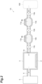
- FIG. 2 is a schematic view showing a modified example of the gas measuring device.
- a gas measuring device 1A shown in FIG. 2 is different from the gas measuring device 1 shown in FIG. 1 in that the porous metal complexes 8b and 9b constituting the filter 7 are stored in containers, respectively, and the rest is the same.
- differences will be mainly described and redundant description will be omitted.
- the suction pipe 6 located upstream of the gas sensor 2 is provided with a first container 12a and a second container 12b.
- the first container 12a and the second container 12b are hollow.
- the first container 12a contains the porous metal complex 8b.
- the second container 12b contains the porous metal complex 9b.
- the first container 12a and the second container 12b have an injection port and an exhaust port.
- the injection port of the first container 12a is configured to allow the introduction of the sample gas 100 from the atmosphere.
- the exhaust port of the first container 12a is connected to the injection port of the second container 12b.
- the exhaust port of the second container 12b is connected to the chamber 3. In this way, the first container 12a and the second container 12b are connected in series and in communication.
- a first valve 13a is provided at the injection port of the first container 12a.
- the first valve 13a is controlled to regulate the flow rate of the sample gas 100 into the first container 12a.
- a second valve 13b is provided in the exhaust port of the first container 12a. By controlling the second valve 13b, the flow rate of the sample gas 100 exhausted from the first container 12a, that is, the flow rate of the sample gas 100 flowing into the second container 12b is adjusted.
- a third valve 13c is provided in the exhaust port of the second container 12b. By controlling the third valve 13c, the flow rate of the sample gas 100 exhausted from the second container 12b, that is, the flow rate of the sample gas 100 flowing into the chamber 3 is adjusted.
- Some or all of the first valve 13a, the second valve 13b, and the third valve 13c may be mass flow controllers.
- the first container 12a and the second container 12b are provided with temperature regulators 11a and 11b to regulate temperature.
- Each constitution of the temperature regulators 11a and 11b is the same as that of the temperature regulator 11, and the background gas adsorbed in the porous metal complexes 8b and 9b can be removed.
- the sample gas 100 flows into the first container 12a, and oxygen gas is removed from the sample gas 100 by the porous metal complex 8b and sent to the second container 12b. Nitrogen gas or rare gases are then removed from the sample gas 100 by the porous metal complex 9b in the second container 12b and sent to the chamber 3.
- the first container 12a and the second container 12b have a structure in which an injection port and an exhaust port thereof can be opened and closed, it is possible to reduce a risk that the porous metal complexes 8b and 9b in powder form are diffused into a measurement system or the atmosphere.
- the first container 12a and the porous metal complex 8b constitute the first filter 8
- the second container 12b and the porous metal complex 9b constitute the second filter 9
- the first container 12a, the porous metal complex 8b, the second container 12b and the porous metal complex 9b constitute the filter 7 in the gas measuring device 1. Therefore, the gas measuring device 1A has the same effect as the gas measuring device 1.
Landscapes
- Chemical & Material Sciences (AREA)
- Engineering & Computer Science (AREA)
- Health & Medical Sciences (AREA)
- Life Sciences & Earth Sciences (AREA)
- Analytical Chemistry (AREA)
- Immunology (AREA)
- Pathology (AREA)
- Physics & Mathematics (AREA)
- Biochemistry (AREA)
- General Health & Medical Sciences (AREA)
- General Physics & Mathematics (AREA)
- Chemical Kinetics & Catalysis (AREA)
- Food Science & Technology (AREA)
- Medicinal Chemistry (AREA)
- General Chemical & Material Sciences (AREA)
- Oil, Petroleum & Natural Gas (AREA)
- Combustion & Propulsion (AREA)
- Biomedical Technology (AREA)
- Molecular Biology (AREA)
- Electrochemistry (AREA)
- Sampling And Sample Adjustment (AREA)
- Investigating Or Analyzing Materials By The Use Of Fluid Adsorption Or Reactions (AREA)
- Separation Of Gases By Adsorption (AREA)
Abstract
Description
- The present disclosure relates to a gas measuring device.
- Patent Document 1 discloses a gas measuring device. The gas measuring device includes a dehumidification cell that performs dehumidification of the sample gas and removal of ethanol in the sample gas, a concentration cell that concentrates the target gas in the dehumidified sample gas by adsorption and desorption, and a MEMS gas sensor that detects the concentrated target gas.
- Patent Document 1:
Japanese Patent Application Publication No. patent publication No. 2020-041833 - The gas measuring device described in Patent Document 1 cannot remove nitrogen gas, oxygen gas, and rare gases, which are main component gases other than water vapor in the atmosphere. Therefore, the gas measuring device described in Patent Document 1 may not be able to detect a trace amount of target gas contained in the atmosphere. The present disclosure provides a gas measuring device capable of improving detection accuracy of target gas in the atmosphere.
- A gas measuring device according to an aspect of the present disclosure includes a filter configured to remove background gas from sample gas in an atmosphere, and a gas sensor configured to detect target gas from the sample gas passed through the filter. The background gas is at least one kind of gas selected from nitrogen gas, oxygen gas and rare gases.
- According to the gas measuring device, at least one kind of gas selected from nitrogen gas, oxygen gas and rare gases is removed from sample gas in the atmosphere by a filter, and target gas is detected from the sample gas by a gas sensor. As described above, since the main component gases in the atmosphere are removed by the filter, the target gas is relatively concentrated. Therefore, the gas measuring device can improve the detection accuracy of the target gas in the atmosphere.
- In one embodiment, the filter may be a porous metal complex in which a metal ion and an organic ligand are bonded. The porous metal complex is less likely to act electrically than a general adsorption member and can remove low-molecular-weight gases. The gas measuring device may appropriately remove nitrogen gas, oxygen gas, and rare gases by using the porous metal complex as a filter.
- In one embodiment, the filter may include a breathable bag configured to contain the porous metal complex in powder form. In this case, the gas measuring device can adjust the amount and accommodation form of the porous metal complex according to the flow rate of the passing sample gas or the shape of the flow path, and can reduce the risk that the porous metal complex in powder form diffuses into the measurement system or the atmosphere.
- In one embodiment, the filter may have a container configured to accommodate the porous metal complex in powder form, and the container may include an injection port for injecting the sample gas and an exhaust port for exhausting the sample gas. In this case, the gas measuring device can reduce the risk of diffusion of the porous metal complex in powder form into the measurement system or the atmosphere.
- In one embodiment, the filter may include a first filter formed of the porous metal complex that mainly removes oxygen gas and a second filter disposed downstream of the first filter and formed of the porous metal complex that mainly removes nitrogen gas and rare gases. With such a configuration, for example, when the filter needs to be replaced for maintenance, the operator does not need to replace the entire filter and can replace only the filter that needs maintenance. Therefore, the gas measuring device can improve the maintainability.
- In one embodiment, the first filter may be formed of a porous metal complex in which a metal ion and tetracyanoquinodimethane are bonded, and the second filter may be formed of a porous metal complex in which metal ion and terephthalic acid are bonded or metal ion and methylene are bonded. Since the relatively low molecular weight tetracyanoquinodimethane and the relatively low molecular weight terephthalic acid or methylene are used as the ligand, the gas measuring device may reduce the gap in the porous metal complex. Therefore, the gas measuring device can selectively take in only low-molecular-weight gases from the sample gas.
- According to the gas measuring device of the present disclosure, it is possible to improve target gas in the atmosphere can be improved.
-
-
FIG. 1 is a schematic diagram illustrating an example of a gas measuring device according to an embodiment. -
FIG. 2 is a schematic view showing a modified example of the gas measuring device according to the embodiment. - Hereinafter, embodiments of the present disclosure will be described with reference to the drawings. In the following description, the same or corresponding elements are denoted by the same reference numerals, and redundant description will not be repeated. The dimensional ratios in the drawings are not necessarily consistent with those in the description. The terms "up", "down", "left" and "right" are based on the illustrated state and are for convenience.
-
FIG. 1 is a schematic diagram illustrating an example of a gas measuring device according to an embodiment. A gas measuring device 1 shown inFIG. 1 is a device for detecting target gas fromsample gas 100. Thesample gas 100 is gas in the atmosphere, and mainly contains at least one gas selected from nitrogen (N2) gas, oxygen (O2) gas, and rare gases. The rare gases is, for example, helium (He) and neon (Ne). Thesample gas 100 may include water vapor or H2 gas. Thesample gas 100 may be acquired from a closed space. - As shown in
FIG. 1 , the gas measuring device 1 includes agas sensor 2. Thegas sensor 2 may be any gas sensor of a semiconductor type, an electrochemical type, a quartz oscillator type, or the like. Thegas sensor 2 is configured to detect a target gas contained in thesample gas 100. The target gas is, for example, acetic acid (CH3COOH), but is not limited thereto. - The
gas sensor 2 is housed inside achamber 3. Thechamber 3 is connected to avacuum pump 5 via anexhaust pipe 4, and the internal space is decompressed. Asuction pipe 6 is connected to thechamber 3. When thevacuum pump 5 decompresses the interior space of thechamber 3, thesample gas 100 is drawn from thesuction pipe 6 into the interior space of thechamber 3. Thegas sensor 2 detects the target gas from thesample gas 100 drawn into the interior space of thechamber 3. - On the upstream side of the
gas sensor 2, here inside thesuction pipe 6, afilter 7 is placed. Thefilter 7 removes background gas from thesample gas 100. Thefilter 7 may remove the background gas from thesample gas 100 without adsorbing the target gas. The background gas is gas other than the target gas. The background gas is at least one kind of gas selected from N2 gas, O2 gas, and rare gases. - The
filter 7 has afirst filter 8 and asecond filter 9. Thefirst filter 8 has abreathable bag 8a. Thebag 8a is formed of a nonwoven fabric, for example. The shape of thebag 8a can be adjusted to fit against the interior wall of thesuction pipe 6. Thebag 8a containsporous metal complex 8b in powder form therein. Theporous metal complex 8b is a compound in which a metal ion and an organic ligand are bonded. Theporous metal complex 8b is a metal-organic framework (MOF: Metal Organic Framework) or a porous coordination polymer (PCP: Porous Coordination Polymer). Theporous metal complex 8b may also be zeolite or porous silica. Theporous metal complex 8b primarily removes oxygen gas and water vapor as an example. Theporous metal complex 8b may be, for example, a porous metal complex in which metal ion and tetracyanoquinodimethane (TCNQ) are bonded. As the metal ions, ions of a type in which coordination is unsaturated may be selected. - The
second filter 9 is disposed downstream of thefirst filter 8. Thesecond filter 9 has abreathable bag 9a. Thebag 9a is formed of a nonwoven fabric, for example. The shape of thebag 9a can be adjusted to fit against the interior wall of thesuction pipe 6. Thebag 9a containsporous metal complex 9b in powder form therein. Theporous metal complex 9b is a compound in which a metal ion and an organic ligand are bonded. Theporous metal complex 9b is a metal-organic framework or a porous coordination polymer. Theporous metal complex 9b primarily removes nitrogen gas and rare gases by way of example. Theporous metal complex 9b may be, for example, a porous metal complex in which metal ions are bonded to terephthalic acid or methylene. As the metal ions, ions of a type in which coordination is unsaturated may be selected. Note that thesuction pipe 6 may be formed of a soft tube. In this case, thefirst filter 8 and thesecond filter 9 can be easily placed and taken out. - A
partition member 10 may be provided between thechamber 3 and thefilter 7. Thepartition member 10 is, for example, a member which is disposed at a connection port between thechamber 3 and thesuction pipe 6 and has an inside diameter smaller than that of thesuction pipe 6. By providing thepartition member 10, thefilter 7 is prevented from being pushed into thechamber 3 by the pressure of thesuction pipe 6. - The gas measuring device 1 may include a
temperature regulator 11 for adjusting the temperature of thefilter 7. Thetemperature regulator 11 is, for example, a heater provided in thesuction pipe 6. Since thesuction pipe 6 is heated by thetemperature regulator 11, the background gas adsorbed to theporous metal complexes porous metal complexes - When the
vacuum pump 5 operates, the internal space of thechamber 3 is decompressed. This draws thesample gas 100 into thesuction pipe 6. The drawnsample gas 100 passes through thefirst filter 8. At this time, oxygen gas and water vapor contained in thesample gas 100 are removed by theporous metal complex 8b of thefirst filter 8. Subsequently, thesample gas 100 passes through thesecond filter 9. At this time, nitrogen gas and rare gases contained in thesample gas 100 are removed by theporous metal complex 9b of thesecond filter 9. As a result, the main component of the atmosphere in thesample gas 100 is removed, and the concentration of the target gas in thesample gas 100 increases. The target gas concentrated in thechamber 3 is detected by thegas sensor 2. - When the removing function of
filter 7 is recovered, the operation of thegas sensor 2 is ended and thevacuum pump 5 and thetemperature regulator 11 are operated. According to the temperature rise of thesuction pipe 6, the background gas adsorbed on theporous metal complexes chamber 3. In this way, the removing function offilter 7 can be restored without removing thesuction pipe 6. - According to the gas measuring device 1, target gas contained in the
sample gas 100 in the atmosphere is not adsorbed by thefilter 7, nitrogen gas, oxygen gas, or rare gases are removed from thesample gas 100, and the target gas is detected in thesample gas 100 by thegas sensor 2. Nitrogen gas, oxygen gas or rare gases is contained in a large amount in the atmosphere and becomes a factor of lowering the detection sensitivity of thegas sensor 2. Since the main component gas in the atmosphere is removed by thefilter 7, the gas that lower the detection sensitivity are removed and the target gas is relatively concentrated. Therefore, the gas measuring device 1 can improve the detection accuracy of the target gas in the atmosphere. In addition, according to the gas measuring device 1, since the target gas is relatively concentrated, it is not necessary to prepare a dedicated concentrator or the like for each gas type of the target gas, and it is possible to easily increase detection accuracy of the target gas. That is, the gas measuring device 1 can provide a concentration function that can be used universally regardless of the type of gas sensor. - Since the
filter 7 including theporous metal complexes - In the gas measuring device 1, since the
filter 7 includes thebags porous metal complexes porous metal complexes sample gas 100 or the internal shape of thesuction pipe 6, and the risk of diffusion of theporous metal complexes - In the gas measuring device 1, since the
filter 7 has a dual filter structure of thefirst filter 8 and thesecond filter 9, for example, when maintenance for restoring the function of removing oxygen gas is required, the operator does not need to replace the entire thefilter 7 but can replace only thefirst filter 8 requiring maintenance. Therefore, the gas measuring device 1 can improve the maintainability. - While various exemplary embodiments have been described above, various omissions, substitutions and changes may be made without being limited to the exemplary embodiments described above.
- A plurality of gas sensors including the
gas sensor 2 and a gas sensor different from thegas sensor 2 may be disposed in thechamber 3. Theporous metal complexes bags porous metal complexes gas sensor 2. Thefilter 7 may be composed of either a single filter or three or more filters. -
FIG. 2 is a schematic view showing a modified example of the gas measuring device. Agas measuring device 1A shown inFIG. 2 is different from the gas measuring device 1 shown inFIG. 1 in that theporous metal complexes filter 7 are stored in containers, respectively, and the rest is the same. In the following description, differences will be mainly described and redundant description will be omitted. - As shown in
FIG. 2 , thesuction pipe 6 located upstream of thegas sensor 2 is provided with afirst container 12a and asecond container 12b. Thefirst container 12a and thesecond container 12b are hollow. Thefirst container 12a contains theporous metal complex 8b. Thesecond container 12b contains theporous metal complex 9b. - The
first container 12a and thesecond container 12b have an injection port and an exhaust port. The injection port of thefirst container 12a is configured to allow the introduction of thesample gas 100 from the atmosphere. The exhaust port of thefirst container 12a is connected to the injection port of thesecond container 12b. The exhaust port of thesecond container 12b is connected to thechamber 3. In this way, thefirst container 12a and thesecond container 12b are connected in series and in communication. - A
first valve 13a is provided at the injection port of thefirst container 12a. Thefirst valve 13a is controlled to regulate the flow rate of thesample gas 100 into thefirst container 12a. Asecond valve 13b is provided in the exhaust port of thefirst container 12a. By controlling thesecond valve 13b, the flow rate of thesample gas 100 exhausted from thefirst container 12a, that is, the flow rate of thesample gas 100 flowing into thesecond container 12b is adjusted. Athird valve 13c is provided in the exhaust port of thesecond container 12b. By controlling thethird valve 13c, the flow rate of thesample gas 100 exhausted from thesecond container 12b, that is, the flow rate of thesample gas 100 flowing into thechamber 3 is adjusted. Some or all of thefirst valve 13a, thesecond valve 13b, and thethird valve 13c may be mass flow controllers. - The
first container 12a and thesecond container 12b are provided withtemperature regulators temperature regulators temperature regulator 11, and the background gas adsorbed in theporous metal complexes - In the
gas measuring device 1A configured as described above, thesample gas 100 flows into thefirst container 12a, and oxygen gas is removed from thesample gas 100 by theporous metal complex 8b and sent to thesecond container 12b. Nitrogen gas or rare gases are then removed from thesample gas 100 by theporous metal complex 9b in thesecond container 12b and sent to thechamber 3. In addition, since thefirst container 12a and thesecond container 12b have a structure in which an injection port and an exhaust port thereof can be opened and closed, it is possible to reduce a risk that theporous metal complexes first container 12a and theporous metal complex 8b constitute thefirst filter 8, thesecond container 12b and theporous metal complex 9b constitute thesecond filter 9, and thefirst container 12a, theporous metal complex 8b, thesecond container 12b and theporous metal complex 9b constitute thefilter 7 in the gas measuring device 1. Therefore, thegas measuring device 1A has the same effect as the gas measuring device 1. - 1, 1A...gas measuring device, 2...gas sensor, 7...filter, 8...first filter, 9... second filter, 8a, 9a...bag, 8b, 9b..porous metal complex, 12a...first container, 12b... second container, 100... sample gas.
Claims (6)
- A gas measuring device comprising:a filter configured to remove background gas from sample gas in an atmosphere; anda gas sensor configured to detect target gas from the sample gas passed through the filter;wherein the background gas is at least one kind of gas selected from nitrogen gas, oxygen gas, and rare gases.
- The gas measuring device according to claim 1, wherein the filter comprises a porous metal complex in which a metal ion and an organic ligand are bonded.
- The gas measuring device according to claim 2, wherein the filter comprises a breathable bag configured to contain the porous metal complex in powder form.
- The gas measuring device according to claim 2, wherein the filter has a container configured to accommodate the porous metal complex in powder form, and the container includes an injection port for injecting the sample gas and an exhaust port for exhausting the sample gas.
- The gas measuring device according to any one of claims 2 to 4, wherein the filter includes:a first filter formed of the porous metal complex that mainly removes oxygen gas; anda second filter disposed downstream of the first filter and formed of the porous metal complex that mainly removes nitrogen gas and rare gases.
- The gas measuring device according to claim 5, wherein the first filter is formed of the porous metal complex in which metal ion and tetracyanoquinodimethane are bonded, and the second filter is formed of the porous metal complex in which metal ion and terephthalic acid are bonded, or metal ion and methylene are bonded.
Applications Claiming Priority (2)
| Application Number | Priority Date | Filing Date | Title |
|---|---|---|---|
| JP2021170308A JP7679751B2 (en) | 2021-10-18 | 2021-10-18 | Gas Measuring Instruments |
| PCT/JP2022/034284 WO2023067955A1 (en) | 2021-10-18 | 2022-09-13 | Gas measuring instrument |
Publications (2)
| Publication Number | Publication Date |
|---|---|
| EP4414048A1 true EP4414048A1 (en) | 2024-08-14 |
| EP4414048A4 EP4414048A4 (en) | 2025-10-15 |
Family
ID=86059031
Family Applications (1)
| Application Number | Title | Priority Date | Filing Date |
|---|---|---|---|
| EP22883265.5A Pending EP4414048A4 (en) | 2021-10-18 | 2022-09-13 | GAS DETECTOR |
Country Status (5)
| Country | Link |
|---|---|
| US (1) | US20240410795A1 (en) |
| EP (1) | EP4414048A4 (en) |
| JP (1) | JP7679751B2 (en) |
| CN (1) | CN118103698A (en) |
| WO (1) | WO2023067955A1 (en) |
Family Cites Families (11)
| Publication number | Priority date | Publication date | Assignee | Title |
|---|---|---|---|---|
| JPH0275951A (en) * | 1988-09-12 | 1990-03-15 | Hitachi Ltd | Instrument for measuring adsorptivity of activated carbon |
| JPH06265507A (en) * | 1993-03-15 | 1994-09-22 | Mitsubishi Electric Corp | Carbon dioxide measuring device |
| US6277329B1 (en) * | 1999-03-22 | 2001-08-21 | Camp Dresser & Mckee Inc. | Dissolved hydrogen analyzer |
| JP2001000822A (en) | 1999-06-21 | 2001-01-09 | Shimizu Corp | Chemical filter |
| US6473175B1 (en) * | 2000-04-19 | 2002-10-29 | Praxair Technology, Inc. | Method for analyzing impurities in a gas stream |
| JP2006313105A (en) | 2005-05-09 | 2006-11-16 | Meiji Univ | Concentration method of benzene in air, measurement method of benzene concentration in air, and filter system for concentration of benzene in air |
| JP5988896B2 (en) | 2013-02-28 | 2016-09-07 | 新日鐵住金株式会社 | Porous polymer metal complex, gas adsorbent, gas separation device and gas storage device using the same |
| JP6653175B2 (en) | 2016-01-07 | 2020-02-26 | 紀本電子工業株式会社 | Volatile organic compound measuring device and volatile organic compound measuring method |
| JP6676406B2 (en) | 2016-02-25 | 2020-04-08 | 日本製鉄株式会社 | Three-dimensional porous polymer metal complex, gas adsorbent using it, gas separation device, gas storage device, catalyst, conductive material, sensor |
| JP2019147697A (en) | 2018-02-26 | 2019-09-05 | 株式会社Ihi | Oxygen gas production device |
| JP7060217B2 (en) | 2018-09-07 | 2022-04-26 | フィガロ技研株式会社 | Gas detector |
-
2021
- 2021-10-18 JP JP2021170308A patent/JP7679751B2/en active Active
-
2022
- 2022-09-13 EP EP22883265.5A patent/EP4414048A4/en active Pending
- 2022-09-13 CN CN202280069406.8A patent/CN118103698A/en active Pending
- 2022-09-13 WO PCT/JP2022/034284 patent/WO2023067955A1/en not_active Ceased
- 2022-09-13 US US18/699,010 patent/US20240410795A1/en active Pending
Also Published As
| Publication number | Publication date |
|---|---|
| WO2023067955A1 (en) | 2023-04-27 |
| JP2023060618A (en) | 2023-04-28 |
| CN118103698A (en) | 2024-05-28 |
| US20240410795A1 (en) | 2024-12-12 |
| EP4414048A4 (en) | 2025-10-15 |
| JP7679751B2 (en) | 2025-05-20 |
Similar Documents
| Publication | Publication Date | Title |
|---|---|---|
| US5457316A (en) | Method and apparatus for the detection and identification of trace gases | |
| CN101014854B (en) | Gas monitoring assembly including one or more gas sensors and one or more getters and methods of use thereof | |
| CN102998362B (en) | The Field adjustment of mass spectrometer system | |
| Dementyev et al. | Vapour permeation measurements with free-standing nanomembranes | |
| KR101107196B1 (en) | Gas Separation Device and Gas Separation Method | |
| CN209471083U (en) | A kind of non-methane total hydrocarbons content detection device | |
| WO2003047731A1 (en) | Gas supplying method and system | |
| CN113702481B (en) | A nitrogen and xenon purification system in water and isotope static analysis method thereof | |
| US9664657B2 (en) | Pulsed admission of analyte to detection apparatus | |
| CN101206204A (en) | Miniature time-of-flight mass spectrometry online sample enrichment device | |
| CN106442823A (en) | VOC (volatile organic compound) analyzer with carrier gas regeneration function | |
| CN103871823A (en) | Membrane-inlet ion mobility spectrometer doped with organic solvent | |
| CN115343391A (en) | System and method for chromatographic analysis of isotopic gas components | |
| US20240410795A1 (en) | Gas measuring instrument | |
| JP6227537B2 (en) | System and method for performing leak inspection | |
| CN107727774A (en) | Multi-sensor chromatography detector and detection method | |
| JP5317692B2 (en) | Plasma spectroscopy system with gas supply | |
| JP2010286476A (en) | High-sensitivity gas analyzer, gas determination method and analyzer system | |
| JP2004264282A (en) | Method for concentrating gaseous substance, and apparatus for concentrating and analyzing carrier gas | |
| CN117310011A (en) | A helium ion gas chromatograph suitable for detection of SF6 decomposition products | |
| CN112986447A (en) | Gas chromatography device | |
| Ma et al. | Atmospheric pressure ionization mass spectroscopy for the study of permeation in polymeric tubing | |
| JP4824322B2 (en) | Activation method of hydrogen adsorbent | |
| JP2000210525A (en) | Operation control device in oxygen concentrator | |
| JP2009122001A (en) | Hydrogen sulfide removal filter for gas detector |
Legal Events
| Date | Code | Title | Description |
|---|---|---|---|
| STAA | Information on the status of an ep patent application or granted ep patent |
Free format text: STATUS: THE INTERNATIONAL PUBLICATION HAS BEEN MADE |
|
| PUAI | Public reference made under article 153(3) epc to a published international application that has entered the european phase |
Free format text: ORIGINAL CODE: 0009012 |
|
| STAA | Information on the status of an ep patent application or granted ep patent |
Free format text: STATUS: REQUEST FOR EXAMINATION WAS MADE |
|
| 17P | Request for examination filed |
Effective date: 20240506 |
|
| AK | Designated contracting states |
Kind code of ref document: A1 Designated state(s): AL AT BE BG CH CY CZ DE DK EE ES FI FR GB GR HR HU IE IS IT LI LT LU LV MC MK MT NL NO PL PT RO RS SE SI SK SM TR |
|
| DAV | Request for validation of the european patent (deleted) | ||
| DAX | Request for extension of the european patent (deleted) | ||
| A4 | Supplementary search report drawn up and despatched |
Effective date: 20250912 |
|
| RIC1 | Information provided on ipc code assigned before grant |
Ipc: B01D 53/04 20060101AFI20250908BHEP Ipc: G01N 27/12 20060101ALI20250908BHEP Ipc: G01N 33/00 20060101ALI20250908BHEP |