EP4413290B1 - Led filament with heat sink - Google Patents
Led filament with heat sink Download PDFInfo
- Publication number
- EP4413290B1 EP4413290B1 EP22793570.7A EP22793570A EP4413290B1 EP 4413290 B1 EP4413290 B1 EP 4413290B1 EP 22793570 A EP22793570 A EP 22793570A EP 4413290 B1 EP4413290 B1 EP 4413290B1
- Authority
- EP
- European Patent Office
- Prior art keywords
- heat sink
- led filament
- leds
- light
- led
- Prior art date
- Legal status (The legal status is an assumption and is not a legal conclusion. Google has not performed a legal analysis and makes no representation as to the accuracy of the status listed.)
- Active
Links
Images


Classifications
-
- F—MECHANICAL ENGINEERING; LIGHTING; HEATING; WEAPONS; BLASTING
- F21—LIGHTING
- F21K—NON-ELECTRIC LIGHT SOURCES USING LUMINESCENCE; LIGHT SOURCES USING ELECTROCHEMILUMINESCENCE; LIGHT SOURCES USING CHARGES OF COMBUSTIBLE MATERIAL; LIGHT SOURCES USING SEMICONDUCTOR DEVICES AS LIGHT-GENERATING ELEMENTS; LIGHT SOURCES NOT OTHERWISE PROVIDED FOR
- F21K9/00—Light sources using semiconductor devices as light-generating elements, e.g. using light-emitting diodes [LED] or lasers
- F21K9/20—Light sources comprising attachment means
- F21K9/23—Retrofit light sources for lighting devices with a single fitting for each light source, e.g. for substitution of incandescent lamps with bayonet or threaded fittings
- F21K9/232—Retrofit light sources for lighting devices with a single fitting for each light source, e.g. for substitution of incandescent lamps with bayonet or threaded fittings specially adapted for generating an essentially omnidirectional light distribution, e.g. with a glass bulb
-
- F—MECHANICAL ENGINEERING; LIGHTING; HEATING; WEAPONS; BLASTING
- F21—LIGHTING
- F21K—NON-ELECTRIC LIGHT SOURCES USING LUMINESCENCE; LIGHT SOURCES USING ELECTROCHEMILUMINESCENCE; LIGHT SOURCES USING CHARGES OF COMBUSTIBLE MATERIAL; LIGHT SOURCES USING SEMICONDUCTOR DEVICES AS LIGHT-GENERATING ELEMENTS; LIGHT SOURCES NOT OTHERWISE PROVIDED FOR
- F21K9/00—Light sources using semiconductor devices as light-generating elements, e.g. using light-emitting diodes [LED] or lasers
- F21K9/20—Light sources comprising attachment means
- F21K9/23—Retrofit light sources for lighting devices with a single fitting for each light source, e.g. for substitution of incandescent lamps with bayonet or threaded fittings
- F21K9/237—Details of housings or cases, i.e. the parts between the light-generating element and the bases; Arrangement of components within housings or cases
-
- F—MECHANICAL ENGINEERING; LIGHTING; HEATING; WEAPONS; BLASTING
- F21—LIGHTING
- F21V—FUNCTIONAL FEATURES OR DETAILS OF LIGHTING DEVICES OR SYSTEMS THEREOF; STRUCTURAL COMBINATIONS OF LIGHTING DEVICES WITH OTHER ARTICLES, NOT OTHERWISE PROVIDED FOR
- F21V11/00—Screens not covered by groups F21V1/00, F21V3/00, F21V7/00 or F21V9/00
- F21V11/08—Screens not covered by groups F21V1/00, F21V3/00, F21V7/00 or F21V9/00 using diaphragms containing one or more apertures
- F21V11/14—Screens not covered by groups F21V1/00, F21V3/00, F21V7/00 or F21V9/00 using diaphragms containing one or more apertures with many small apertures
-
- F—MECHANICAL ENGINEERING; LIGHTING; HEATING; WEAPONS; BLASTING
- F21—LIGHTING
- F21V—FUNCTIONAL FEATURES OR DETAILS OF LIGHTING DEVICES OR SYSTEMS THEREOF; STRUCTURAL COMBINATIONS OF LIGHTING DEVICES WITH OTHER ARTICLES, NOT OTHERWISE PROVIDED FOR
- F21V29/00—Protecting lighting devices from thermal damage; Cooling or heating arrangements specially adapted for lighting devices or systems
- F21V29/50—Cooling arrangements
- F21V29/70—Cooling arrangements characterised by passive heat-dissipating elements, e.g. heat-sinks
-
- F—MECHANICAL ENGINEERING; LIGHTING; HEATING; WEAPONS; BLASTING
- F21—LIGHTING
- F21V—FUNCTIONAL FEATURES OR DETAILS OF LIGHTING DEVICES OR SYSTEMS THEREOF; STRUCTURAL COMBINATIONS OF LIGHTING DEVICES WITH OTHER ARTICLES, NOT OTHERWISE PROVIDED FOR
- F21V29/00—Protecting lighting devices from thermal damage; Cooling or heating arrangements specially adapted for lighting devices or systems
- F21V29/50—Cooling arrangements
- F21V29/70—Cooling arrangements characterised by passive heat-dissipating elements, e.g. heat-sinks
- F21V29/74—Cooling arrangements characterised by passive heat-dissipating elements, e.g. heat-sinks with fins or blades
- F21V29/76—Cooling arrangements characterised by passive heat-dissipating elements, e.g. heat-sinks with fins or blades with essentially identical parallel planar fins or blades, e.g. with comb-like cross-section
- F21V29/763—Cooling arrangements characterised by passive heat-dissipating elements, e.g. heat-sinks with fins or blades with essentially identical parallel planar fins or blades, e.g. with comb-like cross-section the planes containing the fins or blades having the direction of the light emitting axis
-
- F—MECHANICAL ENGINEERING; LIGHTING; HEATING; WEAPONS; BLASTING
- F21—LIGHTING
- F21V—FUNCTIONAL FEATURES OR DETAILS OF LIGHTING DEVICES OR SYSTEMS THEREOF; STRUCTURAL COMBINATIONS OF LIGHTING DEVICES WITH OTHER ARTICLES, NOT OTHERWISE PROVIDED FOR
- F21V5/00—Refractors for light sources
- F21V5/002—Refractors for light sources using microoptical elements for redirecting or diffusing light
-
- F—MECHANICAL ENGINEERING; LIGHTING; HEATING; WEAPONS; BLASTING
- F21—LIGHTING
- F21Y—INDEXING SCHEME ASSOCIATED WITH SUBCLASSES F21K, F21L, F21S and F21V, RELATING TO THE FORM OR THE KIND OF THE LIGHT SOURCES OR OF THE COLOUR OF THE LIGHT EMITTED
- F21Y2103/00—Elongate light sources, e.g. fluorescent tubes
- F21Y2103/10—Elongate light sources, e.g. fluorescent tubes comprising a linear array of point-like light-generating elements
-
- F—MECHANICAL ENGINEERING; LIGHTING; HEATING; WEAPONS; BLASTING
- F21—LIGHTING
- F21Y—INDEXING SCHEME ASSOCIATED WITH SUBCLASSES F21K, F21L, F21S and F21V, RELATING TO THE FORM OR THE KIND OF THE LIGHT SOURCES OR OF THE COLOUR OF THE LIGHT EMITTED
- F21Y2107/00—Light sources with three-dimensionally disposed light-generating elements
-
- F—MECHANICAL ENGINEERING; LIGHTING; HEATING; WEAPONS; BLASTING
- F21—LIGHTING
- F21Y—INDEXING SCHEME ASSOCIATED WITH SUBCLASSES F21K, F21L, F21S and F21V, RELATING TO THE FORM OR THE KIND OF THE LIGHT SOURCES OR OF THE COLOUR OF THE LIGHT EMITTED
- F21Y2113/00—Combination of light sources
- F21Y2113/10—Combination of light sources of different colours
- F21Y2113/13—Combination of light sources of different colours comprising an assembly of point-like light sources
- F21Y2113/17—Combination of light sources of different colours comprising an assembly of point-like light sources forming a single encapsulated light source
-
- F—MECHANICAL ENGINEERING; LIGHTING; HEATING; WEAPONS; BLASTING
- F21—LIGHTING
- F21Y—INDEXING SCHEME ASSOCIATED WITH SUBCLASSES F21K, F21L, F21S and F21V, RELATING TO THE FORM OR THE KIND OF THE LIGHT SOURCES OR OF THE COLOUR OF THE LIGHT EMITTED
- F21Y2113/00—Combination of light sources
- F21Y2113/30—Combination of light sources of visible and non-visible spectrum
-
- F—MECHANICAL ENGINEERING; LIGHTING; HEATING; WEAPONS; BLASTING
- F21—LIGHTING
- F21Y—INDEXING SCHEME ASSOCIATED WITH SUBCLASSES F21K, F21L, F21S and F21V, RELATING TO THE FORM OR THE KIND OF THE LIGHT SOURCES OR OF THE COLOUR OF THE LIGHT EMITTED
- F21Y2115/00—Light-generating elements of semiconductor light sources
- F21Y2115/10—Light-emitting diodes [LED]
Definitions
- the present invention generally relates to lighting arrangements comprising one or more light emitting diodes, LEDs. More specifically, the present invention is related to a LED filament with a heat sink.
- LED light emitting diodes
- LEDs provide numerous advantages such as a longer operational life, a reduced power consumption, and an increased efficiency related to the ratio between light energy and heat energy.
- LED filament lamps are highly appreciated as they are very decorative.
- LEDs Due to the advantageous aspects of the use of LEDs, the interest has rapidly increased to replace conventional light sources with LEDs in many lighting arrangements. It will be appreciated that this replacement, also called retrofitting, is appreciated and desired by users who wish to have the look of an incandescent bulb.
- the light source replacement is often performed by removing the conventional light source(s) from the luminaire (e.g. a lamp holder) of the lighting arrangement and attaching the LEDs, LED arrangement(s) or LED device(s) into the luminaire.
- the luminaire e.g. a lamp holder
- a recent development is the use of LED filaments in high performance lighting applications such as high brightness and/or high luminous flux lamps and luminaires.
- the design or construction of a lighting device needs to take into account the evacuation of heat generated by the LED filaments. It should be noted that the effect of heat may be detrimental to the LED filaments, and their operation may hereby become erratic and unstable.
- thermal management is an important issue to prevent thermal damage of the LED filaments, and it is necessary to dissipate excess heat in order to maintain the reliability of the lighting device and to prevent premature failure of the LED filaments.
- US 2016/178133 discloses an LED lead frame assembly includes a circuit strip assembly, a plastic dam member overmoulded onto the circuit strip assembly and a LED chip assembly disposed in a pocket of the plastic dam member.
- the LED chip assembly is electrically coupled to the circuit strip assembly to power the LED chip assembly.
- CN 203656626U discloses a LED lamp without a metal radiator, comprising at least one LED lamp tube, at least one LED illumination strip is installed in each bulb shell, each illumination strip is provided with metal cooling fins and comprises a metal substrate, at least one metal cooling fin which is integrated with the metal substrate, a light reflecting layer arranged on the metal substrate, at least one string of LED chips arranged on the light reflecting layer, and a transparent medium layer or a luminescent powder layer, the LED chips are coated with the transparent medium layer or the luminescent powder layer,
- a LED lamp filament comprising: a long strip-shaped substrate, a plurality of light-emitting units arranged on a first surface of the substrate and distributed along the extending direction of the substrate, and a light-transmittable fluorescent glue layer covering the first surface and the plurality of light-emitting units.
- a plurality of bulges are provided on at least one side of the substrate, and the bulges are distributed along the extending direction of the substrate; one part of light excited by the fluorescent glue layer and emitted from the light-emitting units emits out in a direction towards a second surface, opposite to the first surface, of the substrate from a space between adjacent bulges.
- a light emitting diode, LED, filament configured to emit LED filament light.
- the LED filament comprises an array of a plurality of light emitting diodes, LEDs, configured to emit LED light.
- the LED filament further comprises a carrier arranged to support the plurality of LEDs.
- the LED filament comprises at least one heat sink arranged in thermal connection with the carrier for a dissipation of heat from the plurality of LEDs during operation, wherein the at least one heat sink comprises a base portion extending parallel to the carrier, and a plurality of fins projecting from the base portion.
- the LED filament further comprises an encapsulant comprising a translucent material, wherein the encapsulant at least partially encloses the plurality of LEDs, the carrier and the at least one heat sink, wherein the at least one heat sink comprises a metal foil.
- the present invention is based on the idea of providing a LED filament wherein heat may be conveniently and efficiently dissipated from the LED filament during operation, whilst providing a desired light output by minimizing any obstruction and/or undesired impact of the light emitted from the LED filament.
- the present invention may provide the combination of a desired light output in terms of light distribution and/or aesthetically appealing lighting from the LED filament during operation via the encapsulant, while at the same time optimizing the thermal management of the LED filament via the heat sink(s).
- the present invention is advantageous in that the thermal connection between the carrier of the LED filament and the heat sink(s), e.g. by direct physical contact, ensures an efficient transfer of heat from the LED filament to the heat sink by conduction. More specifically, the LED filament may efficiently dissipate heat generated by the plurality of LEDs during operation via the base portion and/or the fins of the heat sink(s). Consequently, the present invention provides an efficient thermal management of the LED arrangement, thereby minimizing the detrimental effects of heat on the LEDs of the LED filament during operation.
- the present invention is further advantageous in that the encapsulant of the LED filament is able to provide a desired light output, comprising a desired (omnidirectional) distribution of the light as well as an aesthetically decorative or appealing lighting effect.
- the LED filament of the present invention furthermore comprises relatively few components.
- the relatively low number of components is advantageous in that the LED filament is relatively inexpensive to fabricate.
- the relatively low number of components of the LED filament implies an easier recycling, especially compared to devices or arrangements comprising a relatively high number of components which impede an easy disassembling and/or recycling operation.
- the LED filament which is configured or arranged to emit LED filament light, comprises an array of LEDs, which are configured or arranged to emit LED light.
- the LED filament light may comprise the LED light and/or the LED light as affected (e.g. scattered and/or converted) by the encapsulant of the LED filament.
- array it is here meant a linear arrangement or chain of LEDs, or the like, arranged on the LED filament.
- the LED filament further comprises a carrier arranged to support the plurality of LEDs.
- the plurality of LEDs may be arranged, mounted and/or mechanically coupled on/to a carrier (e.g. a substrate), wherein the carrier is configured to mechanically and/or electrically support the LEDs.
- the carrier may be light transmissive and/or reflective.
- the LED filament further comprises at least one heat sink arranged in thermal connection with the carrier for a dissipation of heat from the plurality of LEDs during operation.
- heat sink it is here meant substantially any structure, component, arrangement, or the like, which is configured and/or arranged to dissipate heat.
- the at least one heat sink comprises a base portion extending parallel to the carrier.
- the carrier may be elongated in order to support the array of LEDs of the (elongated) LED filament, the base portion(s) of the heat sink(s) may be elongated.
- the at least one heat sink further comprises a plurality of fins projecting from the base portion.
- the LED filament further comprises an encapsulant comprising a translucent material, wherein the encapsulant at least partially encloses the plurality of LEDs, the carrier and the at least one heat sink.
- encapsulant it is here meant a material, element, arrangement, or the like, which is configured or arranged to at least partially surround, encapsulate and/or enclose the plurality of LEDs, the carrier and the at least one heat sink of the LED filament.
- translucent material it is here meant a material, composition and/or substance which is translucent and/or transparent for visible light.
- the at least one heat sink comprises a metal foil.
- metal foil it is here meant a relatively thin sheet of metal.
- the base portion of the at least one heat sink may comprise or constitute a metal foil.
- the present invention is advantageous in that the (thin) metal foil may be preserve the relatively light, flexible, pliant and/or supple properties of the LED filament.
- the relatively thin metal foil of the present embodiment may provide a desired heat management of the LED filament whilst providing a relatively light, flexible, pliant and/or supple LED filament.
- the present embodiment is further advantageous in that the metal foil may be conveniently arranged in close vicinity, or in physical contact with, the carrier of the LED filament, resulting in a particularly effective transfer of heat from the plurality of LEDs, via the carrier, to the metal foil of the heat sink(s).
- the present embodiment is further advantageous in that the material properties of the metal, providing a high heat conductivity, is particularly advantageous for a transfer of heat from the LEDs during operation.
- the plurality of fins of the at least one heat sink may constitute folds of the base portion of the at least one heat sink.
- the base portion(s) of the heat sink(s) of the LED filament has been folded such that the folds constitute and/or form the plurality of fins.
- the present embodiment is advantageous in that the plurality of fins may be produced and/or provided conveniently from the material of the base portion of the heat sink. It will be appreciated that the present embodiment is particularly advantageous in case the base portion of the heat sink is a metal foil, as the metal foil may be folded easily and conveniently into folds.
- Yet another advantageous aspect of the embodiment of the present invention is that in case the plurality of fins is arranged perpendicular to the carrier of the LED filament, this configuration allows for a desired flexibility of the LED filament in order to arrange the LED filament in a spiral, coil and/or helix configuration.
- the plurality of LEDs may be arranged on a first side of the carrier, and one heat sink of the at least one heat sink may be arranged on a second side of the carrier, opposite the first side of the carrier.
- the array of the plurality of LEDs and the heat sink may be arranged on opposite sides of the (two-sided) carrier.
- the present embodiment is advantageous in that the heat sink may even further minimize any obstruction and/or undesired impact of the light emitted from the LED filament, and consequently, that the LED filament light and/or the LED light may be provided in an even more desirable way with respect to illumination and/or aesthetic purposes.
- the plurality of LEDs and one heat sink of the at least one heat sink may be are arranged on a first side of the carrier.
- the array of the plurality of LEDs and the heat sink may be arranged on the same (first) side of the (two-sided) carrier.
- the present embodiment is advantageous in that the heat transfer to the heat sink from the LEDs and/or carrier may be even more efficient due to arrangement of the LEDs and the heat sink in relatively close vicinity of each other.
- the base portion of the at least one heat sink may comprise a plurality of apertures configured to transmit at least part of the LED filament light through the plurality of apertures.
- apertures it is here meant openings, (through) holes, or the like, of the base portion(s).
- the present embodiment is advantageous in that the apertures of the heat sink(s) may even further minimize any obstruction of the light emitted from the LED filament.
- one of the main purposes of the apertures is to transmit the light from one side of the carrier to the other side of the carrier.
- the transmitted light is basically scattered LED light, as the LEDs are configured to emit light away from the heat sink(s) which is scattered and/or reflected back by the encapsulant, e.g. by a luminescent material and/or scattering particles of the encapsulant.
- the at least one heat sink may comprise at least one of copper, Cu, and aluminum, Al.
- the heat sink(s) may comprise Cu and/or Al.
- the present embodiment is advantageous in that Cu, Al, and/or an alloy thereof have high heat conductivity properties, thereby constituting excellent heat sink material(s).
- the at least one heat sink may further comprise a layer comprising at least one of an electrically insulating material, whereby the layer constitutes an electrical insulation layer, and a reflective material, whereby the layer constitutes a reflective layer having a higher reflectivity than the base portion of the at least one heat sink.
- the heat sink(s) may comprise an electrical insulation layer comprising one or more electrically insulating materials and/or a reflective layer comprising a reflective material.
- reflective layer it is here meant a coating or layer which is configured to reflect incident light.
- a coating or layer of high reflectivity such as aluminum (Al) and/or silver (Ag) may be evaporated on the heat sink.
- the present embodiment is advantageous in that the reflective layer of the heat sink may efficiently reflect the light emitted from the LED filament upon operation.
- the encapsulant may completely enclose the at least one heat sink.
- the heat sink(s) may be completely enclosed by the encapsulant.
- the plurality of fins of the at least one heat sink may protrude the encapsulant and may extend from the encapsulant.
- the encapsulant may comprise at least one of a light-scattering material configured to scatter light emitted from the plurality of LEDs and a luminescent material configured to at least partly convert light emitted from the plurality of LEDs into converted light.
- the encapsulant may comprise a light scattering material configured to scatter the LED light emitted from the plurality of LEDs and/or a luminescent material configured to at least partly convert the LED light emitted from the plurality of LEDs into converted light.
- the encapsulant and the at least one heat sink may be flexible.
- the encapsulant and/or the heat sink(s) may be flexible in that they may flex back to its (their) original shape, i.e. reversibly flexible.
- the encapsulant and/or the heat sink(s) may be flexible in that they may be changed to a new shape and maintained in the new shape, i.e. irreversibly flexible.
- the encapsulant may comprise silicone.
- the present embodiment is advantageous in that silicone is light transmissive and highly resistant against heat and light, thereby mitigating degradation of the encapsulant.
- the base portion of the at least one heat sink may comprise a plurality of apertures configured to transmit at least part of the LED filament light through the plurality of apertures
- the encapsulant may comprise at least one of a light-scattering material configured to scatter light emitted from the plurality of LEDs and a luminescent material configured to at least partly convert light emitted from the plurality of LEDs into converted light
- the encapsulant may be flexible and the at least one heat sink may be flexible
- the LED filament may have at least one of a spiral, meander, coil and helix shape.
- the present embodiment is advantageous in that the features of the LED filament are particularly beneficial for providing the combination of a desired light output in terms of light distribution and/or aesthetically appealing lighting from the LED filament during operation via the encapsulant and the spiral, meander, coil and/or helix shape of the LED filament, while at the same time optimizing the thermal management of the LED filament via the heat sink(s).
- a LED lighting device may comprise a LED filament according to any one of the preceding embodiments.
- the LED lighting device may further comprise a cover comprising an at least partially transparent material, wherein the cover at least partially encloses the LED filament, and an electrical connection connected to the LED filament for a supply of power to the plurality of LEDs of the LED filament.
- cover it is here meant an enclosing element, such as a cap, cover, envelope, or the like, comprising an at least partial translucent and/or transparent material.
- the present embodiment is advantageous in that the LED filament according to the invention may be conveniently arranged in substantially any lighting LED lighting device, such as a LED filament lamp, luminaire, lighting system, or the like.
- the LED lighting device may further comprise a driver for supplying power the LEDs of the LED filament. Additionally, the lighting device may further comprise a controller for individual control of two or more subsets of LEDs of the LED filament, such as a first set of LEDs, a second set of LEDs, etc.
- Fig. 1 shows a LED filament lamp 10 according to the prior art, comprising a plurality of LED filaments 20.
- LED filament lamps 10 of this kind are highly appreciated as they are very decorative, as well as providing numerous advantages compared to incandescent lamps such as a longer operational life, a reduced power consumption, and an increased efficiency related to the ratio between light energy and heat energy.
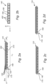
- Fig. 2 schematically shows a LED filament 110 according to an exemplifying embodiment of the present invention.
- the LED filament 110 which elongates along the axis, A, is configured to emit LED filament light.
- the LED filament 110 may preferably have a length, L f , in the range from 1 cm to 20 cm, more preferably 2 cm to 12 cm, and most preferred 3 cm to 10 cm.
- the LED filament 110 may preferably have a width, W f , in the range from 0.5 mm to 10 mm, more preferably 0.8 mm to 8 mm, and most preferred 1 to 5 mm.
- the aspect ratio L f /W f is preferably at least 5, more preferably at least 8, and most preferred at least 10.
- the LED filament 100 comprises an array or "chain” of a plurality of LEDs 120 configured to emit LED light.
- the array or "chain" of the plurality of LEDs 120 may comprise a plurality of adjacently arranged LEDs 120 wherein a respective wiring is provided between each pair of LEDs 120.
- the plurality of LEDs 120 preferably comprises more than 5 LEDs, more preferably more than 8 LEDs, and even more preferred more than 10 LEDs.
- the plurality of LEDs 120 may be direct emitting LEDs which provide a color.
- the LEDs 120 are preferably blue LEDs.
- the LEDs 120 may also be UV LEDs.
- a combination of LEDs 120, e.g. UV LEDs and blue light LEDs, may be used.
- the LEDs 120 may comprise laser diodes.
- the LED filament light emitted from the LED filament 110 during operation is preferably white light.
- the white light is preferably within 15 SDCM from the black body locus (BBL).
- the color temperature of the white light is preferably in the range of 2000 to 6000 K, more preferably in the range from 2100 to 5000 K, most preferably in the range from 2200 to 4000 K such as for example 2300 K or 2700 K.
- the white light has preferably a CRI of at least 75, more preferably at least 80, most preferably at least 85 such as for example 90 or 92.
- the LED filament 110 further comprises a carrier 130 arranged to support the plurality of LEDs 120.
- the plurality of LEDs 120 may be arranged, mounted and/or mechanically coupled on/to the carrier 130.
- the carrier 130 e.g. a substrate, is configured to mechanically and/or electrically support the plurality of LEDs 120.
- the carrier 130 may be a printed circuit board (PCB).
- the carrier 130 may be light transmissive and/or reflective.
- the carrier 130 may be flexible, and may for example comprise a polymer foil (e.g. polyimide (PI), polyethylene terephthalate (PET), etc.).
- the carrier 130 may comprise one or more thermally conductive layers and one or more insulating layers.
- the LED filament 110 further comprises at least one heat sink 140, wherein a single heat sink 140 is exemplified in Fig. 2a .
- the heat sink 140 is arranged adjacent the carrier 130 and is arranged in thermal connection with the carrier 130 for a dissipation of heat from the plurality of LEDs 120 during operation of the LED filament 100.
- the heat sink 140 may be arranged in physical (direct) contact with the carrier 130. It should be noted that the heat sink 140 may constitute and/or have the form of substantially any structure, component, arrangement, or the like, which is configured and/or arranged to dissipate heat.
- the heat sink 140 comprises a base portion (not indicated/shown in Fig. 2a for reasons of visibility) extending parallel to the carrier 130.
- the carrier in Fig. 2a is elongated in order to support the array of LEDs 120 of the (elongated) LED filament 100, and the base portion of the heat sink 140 is hereby also elongated.
- the heat sink 140 further comprises a plurality of fins 160 projecting from its base portion.
- the LED filament 110 may alternatively comprise two heat sinks on either side of the carrier 130.
- the two heat sinks may be the same (or similar), or alternatively, be different, with respect to one or more properties.
- Fig. 2b schematically shows a heat sink 140 of a LED filament 110 according to an exemplifying embodiment of the present invention and corresponds to the heat sink 140 shown in Fig. 2a .
- the base portion 150 of the heat sink 140 comprises a plurality of apertures 400 configured to transmit at least part of the LED filament light through the plurality of apertures 400.
- apertures 400 indentations and/or recesses may be provided.
- the apertures 400 of the base portion 150 are rectangular and are spaced apart with regular intervals, such that the base portion 150 has the shape of a ladder.
- the contact area of the heat sink 140 on the carrier due to the provision of the apertures 400, may be in a range from 20 % to 80 % of the surface area of the carrier/heat sink 140.
- the “steps" of the ladder-shaped base portion 150 correspond to the plurality of fins 160 of the heat sink 140 in Fig. 2a .
- the material of the heat sink 140 is preferably a metal or alloy with a relatively high thermal conductivity, such as copper (Cu) and/or aluminum (Al).
- the heat sink 140 may have a thermal conductivity of at least 200 Wm -1 K -1 , preferably > 250 Wm -1 K -1 , more preferably > 300 Wm -1 K -1 , and most preferably > 350 Wm -1 K -1 .
- the heat sink 140 comprises a metal foil, such as a copper foil.
- the thickness of the metal foil may be constant.
- the thickness of the metal foil may be in a range from 20 to 2000 ⁇ m, preferably 50 to 1000 ⁇ m, even more preferred 80 to 800 ⁇ m, and most preferred 100 to 500 ⁇ m.
- the thermal conductivity of the heat sink 140 is preferably at least 200 W/mK, more preferably more than 250 W/mK, and most preferred more than 300 W/mK.
- the heat sink 140 may be flexible.
- the heat sink 140 may further comprise a layer (not shown) comprising an electrically insulating material, whereby the layer constitutes an electrical insulation layer, and/or a reflective material, whereby the layer constitutes a reflective layer having a higher reflectivity than the base portion 150 of the heat sink 140.
- the reflective layer may reflect the incident light from the LED filament 110 during operation.
- the reflective layer may, for example, comprise a reflective coating.
- the reflective layer or coating may comprise any material of high reflectivity such as aluminum (Al) and/or silver (Ag) which may be evaporated on the heat sink 140.
- the reflective layer may be conveniently applied by chemical vapor deposition (CVD) or physical vapor deposition (PVD).
- the LED filament 110 further comprises an encapsulant 170.
- the encapsulant 170 comprises a translucent material.
- the encapsulant 170 may comprise a light-scattering material configured to scatter light emitted from the plurality of LEDs 120 and/or a luminescent material configured to at least partly convert light emitted from the plurality of LEDs 120 into converted light.
- the light-scattering material may preferably have a reflectivity of > 70 %, more preferably > 80 %, and most preferably > 85 %.
- the encapsulant 170 at least partially encloses the plurality of LEDs 120, the carrier 130 and the heat sink 140.
- the encapsulant 170 fully encloses the plurality of LEDs 120.
- the encapsulant 170 partially encloses the carrier 130, as the length and/or width of the carrier 130 may be longer and/or wider than the length and/or width of the LED filament 110.
- the encapsulant 170 partially encloses the heat sink 140, as the plurality of fins 160 of the heat sink 140 protrudes the encapsulant 170 and extends from the encapsulant 170.
- the cross-section of the encapsulant 170 perpendicular to the axis, A may be circular, but it will be noted that the encapsulant 170 may have substantially any other shape of its cross-section.
- the plurality of LEDs 120 is arranged on a first (front) side 300 of the carrier 130, and one (single) heat sink 140 is arranged on a second (back) side 310 of the carrier 130, wherein the second side 310 of the carrier 130 is arranged opposite the first side 300 of the carrier 130.
- the plurality of LEDs 120 and one (single) heat sink 140 may be arranged on the first side 300 of the carrier 130.
- the LED filament 110 in Fig. 2a heat may be conveniently and efficiently dissipated from the LED filament 110 during operation, whilst minimizing any obstruction of the light emitted from the LED filament 110.
- the LED filament 110 may provide the combination of a desired light distribution from the LED filament 110 during operation, while at the same time optimizing the thermal management of the LED filament 110 via the heat sink 150.
- Fig. 2c shows an alternative embodiment of the LED filament 110 shown in Fig. 2a .
- the encapsulant 170 fully encloses the plurality of LEDs.
- the encapsulant 170 partially encloses the carrier, as the length and/or width of the carrier may be longer and/or wider than the length and/or width of the LED filament 110.
- the encapsulant 170 completely encloses the heat sink 140, including the plurality of fins 160 of the heat sink 140.
- Fig. 2d shows yet another alternative embodiment of the LED filament 110 shown in Fig. 2a and Fig. 2c .
- the encapsulant 170 fully encloses the plurality of LEDs.
- the encapsulant 170 partially encloses the carrier, as the length and/or width of the carrier may be longer and/or wider than the length and/or width of the LED filament 110.
- the length of the plurality of fins 160 of the heat sink 140 correspond to the radius of the encapsulant 170, such that the edges of the plurality of fins 160 of the heat sink 140 are arranged flush with the edge of the encapsulant 170.
- Figs. 2a-d show exemplifying embodiments of LED filament(s) 110, and that the shape and/or number of LED filament(s) may differ from that/those shown.
- the LED filament(s) 100 may have a spiral, meander, coil and/or helix shape.
- Fig. 3a-3c schematically show a provision of a heat sink 140 of a LED filament according to an exemplifying embodiment of the present invention.
- the material and form of the heat sink 140 is provided from a metal foil, preferably a copper foil, which comprises (or alternatively, is provided with in a subsequent manufacturing step) equidistantly arranged apertures.
- the heat sink 140 in form of the metal (copper) foil exemplified in Fig. 3a comprises perforated lines 190 provided equidistantly from the apertures 400. From a folding operation of the heat sink 140 at the perforated lines 190, a plurality of folds 200, e.g.
- N folds 200 wherein N is an integer, of the base portion 150 may be constructed for the heat sink 140, as indicated schematically in Fig. 3c .
- the folds 200 may hereby constitute the plurality of fins 160 of the base portion 150 of the heat sink 140 of the LED filament 110 as indicated in Fig. 2a .
- At least one LED may be arranged between adjacent (neighboring) folds 200.
- the height of the folds 200 may be in a range from 1 to 10 mm, more preferably in a range from 2 to 8 mm, and most preferred in a range from 3 to 5 mm.
- the distance between neighboring folds 200 may be in a range from 0.5 to 10 mm, preferably 1 to 8 mm, even more preferred 2 to 6 mm, and most preferably 3 to 5 mm.
- the pitch (distance) between neighboring folds may be constant.
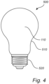
- Fig. 4 schematically shows a LED lighting device 500 according to an embodiment of the present invention.
- the LED lighting device 500 which may constitute a lamp or a luminaire, comprises one or more LED filaments 110 according to any one of the previously described embodiments.
- the LED lighting device 500 further comprises a cover 510, which is exemplified as being bulb-shaped.
- the cover 510 may comprise an at least partially light transmissive (e.g. transparent) material and at least partially encloses the LED filament 110.
- the LED lighting device 500 further comprises an electrical connection 520 connected to the LED filament 110 for a supply of power to the plurality of LEDs of the LED filament 110.
- one or more of the LED filament(s) 110, the heat sink 140, the encapsulant 170, etc. may have different shapes, dimensions and/or sizes than those depicted/described.
Landscapes
- Engineering & Computer Science (AREA)
- General Engineering & Computer Science (AREA)
- Physics & Mathematics (AREA)
- Microelectronics & Electronic Packaging (AREA)
- Optics & Photonics (AREA)
- Non-Portable Lighting Devices Or Systems Thereof (AREA)
- Arrangement Of Elements, Cooling, Sealing, Or The Like Of Lighting Devices (AREA)
Applications Claiming Priority (2)
| Application Number | Priority Date | Filing Date | Title |
|---|---|---|---|
| EP21200925 | 2021-10-05 | ||
| PCT/EP2022/077454 WO2023057380A1 (en) | 2021-10-05 | 2022-10-03 | Led filament with heat sink |
Publications (2)
| Publication Number | Publication Date |
|---|---|
| EP4413290A1 EP4413290A1 (en) | 2024-08-14 |
| EP4413290B1 true EP4413290B1 (en) | 2025-04-23 |
Family
ID=78078106
Family Applications (1)
| Application Number | Title | Priority Date | Filing Date |
|---|---|---|---|
| EP22793570.7A Active EP4413290B1 (en) | 2021-10-05 | 2022-10-03 | Led filament with heat sink |
Country Status (7)
| Country | Link |
|---|---|
| US (1) | US12435844B2 (pl) |
| EP (1) | EP4413290B1 (pl) |
| JP (1) | JP7583512B2 (pl) |
| CN (1) | CN118056090A (pl) |
| ES (1) | ES3027968T3 (pl) |
| PL (1) | PL4413290T3 (pl) |
| WO (1) | WO2023057380A1 (pl) |
Family Cites Families (19)
| Publication number | Priority date | Publication date | Assignee | Title |
|---|---|---|---|---|
| US9995474B2 (en) * | 2015-06-10 | 2018-06-12 | Jiaxing Super Lighting Electric Appliance Co., Ltd. | LED filament, LED filament assembly and LED bulb |
| US8013501B2 (en) * | 2008-06-04 | 2011-09-06 | Forever Bulb, Llc | LED-based light bulb device |
| JP5662059B2 (ja) * | 2010-06-04 | 2015-01-28 | パナソニックIpマネジメント株式会社 | Ledランプ |
| US9410687B2 (en) * | 2012-04-13 | 2016-08-09 | Cree, Inc. | LED lamp with filament style LED assembly |
| US9528689B2 (en) * | 2013-03-13 | 2016-12-27 | Palo Alto Research Center Incorporated | LED lighting device with cured structural support |
| CN203656626U (zh) | 2013-11-28 | 2014-06-18 | 浙江锐迪生光电有限公司 | 一种无金属散热器的大功率led灯 |
| CN103855144B (zh) | 2014-01-06 | 2016-08-17 | 深圳市瑞丰光电子股份有限公司 | Led灯丝及发光装置 |
| CN203910855U (zh) | 2014-05-29 | 2014-10-29 | 惠州市华瑞光源科技有限公司 | Led灯丝 |
| CN104006321B (zh) | 2014-06-06 | 2016-06-22 | 上海鼎晖科技股份有限公司 | 一种3d cob led灯发光组件及led灯 |
| CN203932114U (zh) | 2014-06-18 | 2014-11-05 | 深圳市正东明光电子有限公司 | Led灯丝的散热结构及具有该结构的led灯丝 |
| US9941258B2 (en) * | 2014-12-17 | 2018-04-10 | GE Lighting Solutions, LLC | LED lead frame array for general illumination |
| CN204460087U (zh) | 2015-01-13 | 2015-07-08 | 厦门多彩光电子科技有限公司 | 一种冲压式led灯丝及其发光装置 |
| DE102015120085A1 (de) | 2015-11-19 | 2017-05-24 | Osram Opto Semiconductors Gmbh | LED-Filamente, Verfahren zur Herstellung von LED-Filamenten und Retrofitlampe mit LED-Filament |
| CN207999659U (zh) * | 2018-03-31 | 2018-10-23 | 深圳市华天迈克光电子科技有限公司 | 一种高光效良散热的led内部灯丝封装结构 |
| CN208846103U (zh) * | 2018-09-20 | 2019-05-10 | 泉州三安半导体科技有限公司 | 一种灯丝 |
| CN112969885B (zh) * | 2018-10-29 | 2024-02-09 | 昕诺飞控股有限公司 | 具有散热器结构的led灯丝装置 |
| JP6854863B2 (ja) * | 2019-11-05 | 2021-04-07 | 三菱電機照明株式会社 | 光源ユニット |
| WO2021099201A1 (en) * | 2019-11-21 | 2021-05-27 | Signify Holding B.V. | A light emitting device |
| CN217082227U (zh) * | 2022-05-05 | 2022-07-29 | 池州昀冢电子科技有限公司 | 基于led芯片的灯丝及灯丝灯 |
-
2022
- 2022-10-03 WO PCT/EP2022/077454 patent/WO2023057380A1/en not_active Ceased
- 2022-10-03 CN CN202280066925.9A patent/CN118056090A/zh active Pending
- 2022-10-03 EP EP22793570.7A patent/EP4413290B1/en active Active
- 2022-10-03 ES ES22793570T patent/ES3027968T3/es active Active
- 2022-10-03 PL PL22793570.7T patent/PL4413290T3/pl unknown
- 2022-10-03 US US18/697,816 patent/US12435844B2/en active Active
- 2022-10-03 JP JP2024519973A patent/JP7583512B2/ja active Active
Also Published As
| Publication number | Publication date |
|---|---|
| WO2023057380A1 (en) | 2023-04-13 |
| US20240410536A1 (en) | 2024-12-12 |
| US12435844B2 (en) | 2025-10-07 |
| PL4413290T3 (pl) | 2025-07-07 |
| ES3027968T3 (en) | 2025-06-17 |
| EP4413290A1 (en) | 2024-08-14 |
| JP2024536303A (ja) | 2024-10-04 |
| CN118056090A (zh) | 2024-05-17 |
| JP7583512B2 (ja) | 2024-11-14 |
Similar Documents
| Publication | Publication Date | Title |
|---|---|---|
| JP7503132B2 (ja) | 発光デバイス | |
| US9459000B2 (en) | Thermal conductivity and phase transition heat transfer mechanism including optical element to be cooled by heat transfer of the mechanism | |
| EP2462377B1 (en) | Solid state lighting device with improved heatsink | |
| EP3874196B1 (en) | Led filament arrangement with heat sink structure | |
| WO2013112262A1 (en) | Lamp structure with remote led light source | |
| JP7461956B2 (ja) | Ledフィラメント構成 | |
| KR100646198B1 (ko) | 엘이디 패키지의 열 방출 구조 및 그 구조를 구비한엘이디 패키지 | |
| US12435844B2 (en) | LED filament with heat sink | |
| KR101099572B1 (ko) | Led 조명장치 | |
| KR101188350B1 (ko) | 히트 스프레더를 이용한 엘이디 조명 | |
| KR20100099520A (ko) | 조명 장치 | |
| WO2017013141A1 (en) | Lighting device with light guide | |
| CN113853499A (zh) | 包括基板和散热器结构的光源 | |
| WO2025153399A1 (en) | A led filament lighting device | |
| JP2017162996A (ja) | 発光装置及び照明装置 |
Legal Events
| Date | Code | Title | Description |
|---|---|---|---|
| STAA | Information on the status of an ep patent application or granted ep patent |
Free format text: STATUS: UNKNOWN |
|
| STAA | Information on the status of an ep patent application or granted ep patent |
Free format text: STATUS: THE INTERNATIONAL PUBLICATION HAS BEEN MADE |
|
| PUAI | Public reference made under article 153(3) epc to a published international application that has entered the european phase |
Free format text: ORIGINAL CODE: 0009012 |
|
| STAA | Information on the status of an ep patent application or granted ep patent |
Free format text: STATUS: REQUEST FOR EXAMINATION WAS MADE |
|
| 17P | Request for examination filed |
Effective date: 20240506 |
|
| AK | Designated contracting states |
Kind code of ref document: A1 Designated state(s): AL AT BE BG CH CY CZ DE DK EE ES FI FR GB GR HR HU IE IS IT LI LT LU LV MC ME MK MT NL NO PL PT RO RS SE SI SK SM TR |
|
| GRAP | Despatch of communication of intention to grant a patent |
Free format text: ORIGINAL CODE: EPIDOSNIGR1 |
|
| STAA | Information on the status of an ep patent application or granted ep patent |
Free format text: STATUS: GRANT OF PATENT IS INTENDED |
|
| DAV | Request for validation of the european patent (deleted) | ||
| DAX | Request for extension of the european patent (deleted) | ||
| INTG | Intention to grant announced |
Effective date: 20241120 |
|
| GRAS | Grant fee paid |
Free format text: ORIGINAL CODE: EPIDOSNIGR3 |
|
| P01 | Opt-out of the competence of the unified patent court (upc) registered |
Free format text: CASE NUMBER: APP_6940/2025 Effective date: 20250211 |
|
| GRAA | (expected) grant |
Free format text: ORIGINAL CODE: 0009210 |
|
| STAA | Information on the status of an ep patent application or granted ep patent |
Free format text: STATUS: THE PATENT HAS BEEN GRANTED |
|
| AK | Designated contracting states |
Kind code of ref document: B1 Designated state(s): AL AT BE BG CH CY CZ DE DK EE ES FI FR GB GR HR HU IE IS IT LI LT LU LV MC ME MK MT NL NO PL PT RO RS SE SI SK SM TR |
|
| REG | Reference to a national code |
Ref country code: GB Ref legal event code: FG4D |
|
| REG | Reference to a national code |
Ref country code: CH Ref legal event code: EP |
|
| REG | Reference to a national code |
Ref country code: DE Ref legal event code: R096 Ref document number: 602022013686 Country of ref document: DE |
|
| REG | Reference to a national code |
Ref country code: IE Ref legal event code: FG4D |
|
| REG | Reference to a national code |
Ref country code: SE Ref legal event code: TRGR Ref country code: ES Ref legal event code: FG2A Ref document number: 3027968 Country of ref document: ES Kind code of ref document: T3 Effective date: 20250617 |
|
| REG | Reference to a national code |
Ref country code: NL Ref legal event code: FP |
|
| REG | Reference to a national code |
Ref country code: AT Ref legal event code: MK05 Ref document number: 1788046 Country of ref document: AT Kind code of ref document: T Effective date: 20250423 |
|
| PG25 | Lapsed in a contracting state [announced via postgrant information from national office to epo] |
Ref country code: FI Free format text: LAPSE BECAUSE OF FAILURE TO SUBMIT A TRANSLATION OF THE DESCRIPTION OR TO PAY THE FEE WITHIN THE PRESCRIBED TIME-LIMIT Effective date: 20250423 Ref country code: PT Free format text: LAPSE BECAUSE OF FAILURE TO SUBMIT A TRANSLATION OF THE DESCRIPTION OR TO PAY THE FEE WITHIN THE PRESCRIBED TIME-LIMIT Effective date: 20250825 |
|
| REG | Reference to a national code |
Ref country code: LT Ref legal event code: MG9D |
|
| PG25 | Lapsed in a contracting state [announced via postgrant information from national office to epo] |
Ref country code: NO Free format text: LAPSE BECAUSE OF FAILURE TO SUBMIT A TRANSLATION OF THE DESCRIPTION OR TO PAY THE FEE WITHIN THE PRESCRIBED TIME-LIMIT Effective date: 20250723 Ref country code: GR Free format text: LAPSE BECAUSE OF FAILURE TO SUBMIT A TRANSLATION OF THE DESCRIPTION OR TO PAY THE FEE WITHIN THE PRESCRIBED TIME-LIMIT Effective date: 20250724 |
|
| PGFP | Annual fee paid to national office [announced via postgrant information from national office to epo] |
Ref country code: PL Payment date: 20250922 Year of fee payment: 4 |
|
| PG25 | Lapsed in a contracting state [announced via postgrant information from national office to epo] |
Ref country code: BG Free format text: LAPSE BECAUSE OF FAILURE TO SUBMIT A TRANSLATION OF THE DESCRIPTION OR TO PAY THE FEE WITHIN THE PRESCRIBED TIME-LIMIT Effective date: 20250423 |
|
| PG25 | Lapsed in a contracting state [announced via postgrant information from national office to epo] |
Ref country code: HR Free format text: LAPSE BECAUSE OF FAILURE TO SUBMIT A TRANSLATION OF THE DESCRIPTION OR TO PAY THE FEE WITHIN THE PRESCRIBED TIME-LIMIT Effective date: 20250423 |
|
| PG25 | Lapsed in a contracting state [announced via postgrant information from national office to epo] |
Ref country code: AT Free format text: LAPSE BECAUSE OF FAILURE TO SUBMIT A TRANSLATION OF THE DESCRIPTION OR TO PAY THE FEE WITHIN THE PRESCRIBED TIME-LIMIT Effective date: 20250423 |
|
| PG25 | Lapsed in a contracting state [announced via postgrant information from national office to epo] |
Ref country code: RS Free format text: LAPSE BECAUSE OF FAILURE TO SUBMIT A TRANSLATION OF THE DESCRIPTION OR TO PAY THE FEE WITHIN THE PRESCRIBED TIME-LIMIT Effective date: 20250723 |
|
| PG25 | Lapsed in a contracting state [announced via postgrant information from national office to epo] |
Ref country code: IS Free format text: LAPSE BECAUSE OF FAILURE TO SUBMIT A TRANSLATION OF THE DESCRIPTION OR TO PAY THE FEE WITHIN THE PRESCRIBED TIME-LIMIT Effective date: 20250823 |
|
| PG25 | Lapsed in a contracting state [announced via postgrant information from national office to epo] |
Ref country code: LV Free format text: LAPSE BECAUSE OF FAILURE TO SUBMIT A TRANSLATION OF THE DESCRIPTION OR TO PAY THE FEE WITHIN THE PRESCRIBED TIME-LIMIT Effective date: 20250423 |
|
| PGFP | Annual fee paid to national office [announced via postgrant information from national office to epo] |
Ref country code: NL Payment date: 20251024 Year of fee payment: 4 |
|
| PG25 | Lapsed in a contracting state [announced via postgrant information from national office to epo] |
Ref country code: SM Free format text: LAPSE BECAUSE OF FAILURE TO SUBMIT A TRANSLATION OF THE DESCRIPTION OR TO PAY THE FEE WITHIN THE PRESCRIBED TIME-LIMIT Effective date: 20250423 Ref country code: DK Free format text: LAPSE BECAUSE OF FAILURE TO SUBMIT A TRANSLATION OF THE DESCRIPTION OR TO PAY THE FEE WITHIN THE PRESCRIBED TIME-LIMIT Effective date: 20250423 |
|
| PGFP | Annual fee paid to national office [announced via postgrant information from national office to epo] |
Ref country code: IT Payment date: 20251031 Year of fee payment: 4 |
|
| PGFP | Annual fee paid to national office [announced via postgrant information from national office to epo] |
Ref country code: FR Payment date: 20251027 Year of fee payment: 4 |
|
| PGFP | Annual fee paid to national office [announced via postgrant information from national office to epo] |
Ref country code: SE Payment date: 20251024 Year of fee payment: 4 |
|
| PG25 | Lapsed in a contracting state [announced via postgrant information from national office to epo] |
Ref country code: CZ Free format text: LAPSE BECAUSE OF FAILURE TO SUBMIT A TRANSLATION OF THE DESCRIPTION OR TO PAY THE FEE WITHIN THE PRESCRIBED TIME-LIMIT Effective date: 20250423 |
|
| PG25 | Lapsed in a contracting state [announced via postgrant information from national office to epo] |
Ref country code: EE Free format text: LAPSE BECAUSE OF FAILURE TO SUBMIT A TRANSLATION OF THE DESCRIPTION OR TO PAY THE FEE WITHIN THE PRESCRIBED TIME-LIMIT Effective date: 20250423 |
|
| REG | Reference to a national code |
Ref country code: DE Ref legal event code: R097 Ref document number: 602022013686 Country of ref document: DE |
|
| PG25 | Lapsed in a contracting state [announced via postgrant information from national office to epo] |
Ref country code: SK Free format text: LAPSE BECAUSE OF FAILURE TO SUBMIT A TRANSLATION OF THE DESCRIPTION OR TO PAY THE FEE WITHIN THE PRESCRIBED TIME-LIMIT Effective date: 20250423 |
|
| PGFP | Annual fee paid to national office [announced via postgrant information from national office to epo] |
Ref country code: ES Payment date: 20251118 Year of fee payment: 4 |
|
| PLBE | No opposition filed within time limit |
Free format text: ORIGINAL CODE: 0009261 |
|
| STAA | Information on the status of an ep patent application or granted ep patent |
Free format text: STATUS: NO OPPOSITION FILED WITHIN TIME LIMIT |
|
| REG | Reference to a national code |
Ref country code: CH Ref legal event code: L10 Free format text: ST27 STATUS EVENT CODE: U-0-0-L10-L00 (AS PROVIDED BY THE NATIONAL OFFICE) Effective date: 20260304 |
|
| PG25 | Lapsed in a contracting state [announced via postgrant information from national office to epo] |
Ref country code: RO Free format text: LAPSE BECAUSE OF FAILURE TO SUBMIT A TRANSLATION OF THE DESCRIPTION OR TO PAY THE FEE WITHIN THE PRESCRIBED TIME-LIMIT Effective date: 20250423 |
|
| 26N | No opposition filed |
Effective date: 20260126 |
|
| PGFP | Annual fee paid to national office [announced via postgrant information from national office to epo] |
Ref country code: DE Payment date: 20251229 Year of fee payment: 4 |