EP4412296A1 - Messmessverfahren und zugehörige vorrichtung - Google Patents
Messmessverfahren und zugehörige vorrichtung Download PDFInfo
- Publication number
- EP4412296A1 EP4412296A1 EP22886006.0A EP22886006A EP4412296A1 EP 4412296 A1 EP4412296 A1 EP 4412296A1 EP 22886006 A EP22886006 A EP 22886006A EP 4412296 A1 EP4412296 A1 EP 4412296A1
- Authority
- EP
- European Patent Office
- Prior art keywords
- transmission path
- ppdu
- amplitude
- information
- sensing measurement
- Prior art date
- Legal status (The legal status is an assumption and is not a legal conclusion. Google has not performed a legal analysis and makes no representation as to the accuracy of the status listed.)
- Pending
Links
- 238000000691 measurement method Methods 0.000 title claims abstract description 25
- 238000005259 measurement Methods 0.000 claims abstract description 310
- 230000005540 biological transmission Effects 0.000 claims description 602
- 238000004891 communication Methods 0.000 claims description 237
- 238000000034 method Methods 0.000 claims description 79
- 230000004044 response Effects 0.000 claims description 33
- 238000004590 computer program Methods 0.000 claims description 12
- 238000005516 engineering process Methods 0.000 abstract description 12
- 238000010586 diagram Methods 0.000 description 28
- 238000012545 processing Methods 0.000 description 20
- 230000008569 process Effects 0.000 description 13
- 230000008859 change Effects 0.000 description 8
- 230000008878 coupling Effects 0.000 description 3
- 238000010168 coupling process Methods 0.000 description 3
- 238000005859 coupling reaction Methods 0.000 description 3
- 230000006870 function Effects 0.000 description 3
- 239000003550 marker Substances 0.000 description 3
- 238000004364 calculation method Methods 0.000 description 2
- 238000013461 design Methods 0.000 description 2
- 230000003993 interaction Effects 0.000 description 2
- 230000007774 longterm Effects 0.000 description 2
- 230000009471 action Effects 0.000 description 1
- 238000001514 detection method Methods 0.000 description 1
- 230000000694 effects Effects 0.000 description 1
- 238000009472 formulation Methods 0.000 description 1
- 239000000203 mixture Substances 0.000 description 1
- 230000003287 optical effect Effects 0.000 description 1
- 230000005855 radiation Effects 0.000 description 1
- 230000003595 spectral effect Effects 0.000 description 1
- 238000001228 spectrum Methods 0.000 description 1
Images


Classifications
-
- H—ELECTRICITY
- H04—ELECTRIC COMMUNICATION TECHNIQUE
- H04W—WIRELESS COMMUNICATION NETWORKS
- H04W24/00—Supervisory, monitoring or testing arrangements
- H04W24/10—Scheduling measurement reports ; Arrangements for measurement reports
-
- H—ELECTRICITY
- H04—ELECTRIC COMMUNICATION TECHNIQUE
- H04B—TRANSMISSION
- H04B17/00—Monitoring; Testing
- H04B17/0082—Monitoring; Testing using service channels; using auxiliary channels
- H04B17/0087—Monitoring; Testing using service channels; using auxiliary channels using auxiliary channels or channel simulators
-
- H—ELECTRICITY
- H04—ELECTRIC COMMUNICATION TECHNIQUE
- H04B—TRANSMISSION
- H04B17/00—Monitoring; Testing
- H04B17/30—Monitoring; Testing of propagation channels
- H04B17/309—Measuring or estimating channel quality parameters
- H04B17/318—Received signal strength
-
- H—ELECTRICITY
- H04—ELECTRIC COMMUNICATION TECHNIQUE
- H04B—TRANSMISSION
- H04B17/00—Monitoring; Testing
- H04B17/30—Monitoring; Testing of propagation channels
- H04B17/309—Measuring or estimating channel quality parameters
- H04B17/364—Delay profiles
-
- H—ELECTRICITY
- H04—ELECTRIC COMMUNICATION TECHNIQUE
- H04L—TRANSMISSION OF DIGITAL INFORMATION, e.g. TELEGRAPHIC COMMUNICATION
- H04L25/00—Baseband systems
- H04L25/02—Details ; arrangements for supplying electrical power along data transmission lines
- H04L25/0202—Channel estimation
- H04L25/0212—Channel estimation of impulse response
-
- H—ELECTRICITY
- H04—ELECTRIC COMMUNICATION TECHNIQUE
- H04L—TRANSMISSION OF DIGITAL INFORMATION, e.g. TELEGRAPHIC COMMUNICATION
- H04L25/00—Baseband systems
- H04L25/02—Details ; arrangements for supplying electrical power along data transmission lines
- H04L25/0202—Channel estimation
- H04L25/0224—Channel estimation using sounding signals
- H04L25/0228—Channel estimation using sounding signals with direct estimation from sounding signals
-
- Y—GENERAL TAGGING OF NEW TECHNOLOGICAL DEVELOPMENTS; GENERAL TAGGING OF CROSS-SECTIONAL TECHNOLOGIES SPANNING OVER SEVERAL SECTIONS OF THE IPC; TECHNICAL SUBJECTS COVERED BY FORMER USPC CROSS-REFERENCE ART COLLECTIONS [XRACs] AND DIGESTS
- Y02—TECHNOLOGIES OR APPLICATIONS FOR MITIGATION OR ADAPTATION AGAINST CLIMATE CHANGE
- Y02D—CLIMATE CHANGE MITIGATION TECHNOLOGIES IN INFORMATION AND COMMUNICATION TECHNOLOGIES [ICT], I.E. INFORMATION AND COMMUNICATION TECHNOLOGIES AIMING AT THE REDUCTION OF THEIR OWN ENERGY USE
- Y02D30/00—Reducing energy consumption in communication networks
- Y02D30/70—Reducing energy consumption in communication networks in wireless communication networks
Definitions
- This application relates to the field of communication technologies, and in particular, to a sensing measurement method and a related apparatus.
- UWB Ultra-wideband
- UWB Ultra-WideBand
- a wireless carrier communication technology performs data transmission via a nanosecond-level non-sine wave narrow pulse, and therefore occupies a very wide spectrum range.
- the non-sine wave narrow pulse is very narrow, and has an extremely low radiation spectral density. Therefore, a UWB wireless communication system has advantages such as a strong multipath resolution capability, low power consumption, and strong confidentiality.
- the Federal Communications Commission Federal Communications Commission (Federal Communications Commission, FCC) approved entry of the UWB technology into the civil field, and the UWB technology becomes one of much-talked-about physical layer technologies in a short-distance and high-speed wireless network.
- the IEEE incorporates the UWB technology into the IEEE 802 series wireless standards.
- the IEEE has published the UWB technology-based high-speed wireless personal area network (Wireless Personal Area Network, WPAN) standard IEEE 802.15.4a and an evolved version IEEE 802.15.4z of the standard IEEE 802.15.4a. Formulation of the next generation UWB wireless personal area network standard 802.15.4ab is put on the agenda.
- a signal for wireless communication has a very large bandwidth (a minimum of 500 MHz (megahertz)), and therefore, a high-precision ranging result or a sensing measurement result can be obtained through an ultra-wideband signal.
- a high-precision ranging result or a sensing measurement result can be obtained through an ultra-wideband signal.
- how to implement sensing of a surrounding environment and feed back a sensing measurement result through the ultra-wideband signal is a problem worth considering.
- This application provides a sensing measurement method and a related apparatus, so that a second device can sense a target in a surrounding environment and feed back a corresponding sensing measurement result to a first device.
- a first aspect of this application provides a sensing measurement method.
- the method includes:
- a first device sends a first physical layer protocol data unit (PHY Protocol Data Unit, PPDU) to a second device, where the first PPDU is used for sensing measurement; and the first device receives a second PPDU from the second device, where the second PPDU includes a sensing measurement result, and the sensing measurement result is obtained by the second device by performing sensing measurement on the first PPDU.
- PHY Protocol Data Unit PHY Protocol Data Unit
- the foregoing technical solution is applicable to a UWB wireless communication system, and the first device and the second device may be two UWB devices in the UWB wireless communication system.
- the first device sends the first PPDU to the second device, and then the first device may receive the second PPDU from the second device, where the second PPDU includes the sensing measurement result, and the sensing measurement result is obtained by the second device by performing the sensing measurement on the first PPDU.
- the UWB device can sense a surrounding environment and feed back the corresponding sensing measurement result.
- a second aspect of this application provides a sensing measurement method.
- the method includes:
- a second device receives a first PPDU from a first device; the second device performs sensing measurement on the first PPDU, to obtain a sensing measurement result; and the second device sends a second PPDU to the first device, where the second PPDU includes the sensing measurement result.
- the foregoing technical solution is applicable to a UWB wireless communication system, and the first device and the second device may be two UWB devices in the UWB wireless communication system.
- the second device performs the sensing measurement on the first PPDU, to obtain the sensing measurement result, and feeds back the sensing measurement result to the first device.
- the UWB device can sense a surrounding environment and feed back the corresponding sensing measurement result.
- the sensing measurement result includes at least one of the following: transmission path quantity information, multipath signal component amplitude information, time information, angle information, and location information of the second device.
- the transmission path quantity information indicates a quantity of transmission paths between the first device and the second device
- the multipath signal component amplitude information includes signal amplitude information corresponding to the first PPDU on at least one transmission path between the first device and the second device
- the time information includes time information corresponding to the first PPDU on the at least one transmission path
- the angle information includes information about an angle at which the first PPDU arrives at the second device on the at least one transmission path.
- the foregoing implementation shows specific content of the sensing measurement result, which specifically includes the signal amplitude information, the time information, and the angle information of the first PPDU transmitted on the at least one transmission path between the first device and the second device, the quantity of transmission paths between the first device and the second device, the location information of the second device, and the like.
- the multipath signal component amplitude information includes in-phase signal amplitude information and quadrature signal amplitude information
- the in-phase amplitude information includes amplitude information of an in-phase signal corresponding to the first PPDU on the at least one transmission path
- the quadrature amplitude information includes amplitude information of a quadrature signal corresponding to the first PPDU on the at least one transmission path.
- the multipath signal component amplitude information indicates signal energy of the first PPDU on each transmission path from two dimensions (the in-phase signal of the first PPDU and the quadrature signal of the first PPDU). This helps the first device determine, based on the multipath signal component amplitude information, a signal amplitude change and a signal phase change on each transmission path. Because the phase change of the signal may indicate a moving speed of a target in an environment to some extent, the first device may determine information such as the moving speed of the target based on the multipath signal component amplitude information.
- the in-phase signal amplitude information includes at least one first amplitude difference, the at least one first amplitude difference corresponds to the at least one transmission path, each first amplitude difference is determined based on an amplitude of an in-phase signal of the first PPDU transmitted on a transmission path corresponding to the first amplitude difference and an amplitude of an in-phase signal of the first PPDU transmitted on a first transmission path, and the first transmission path is a transmission path that is in the at least one transmission path and on which the first PPDU has strongest signal energy; and the quadrature signal amplitude information includes at least one second amplitude difference, the at least one second amplitude difference corresponds to the at least one transmission path, and each second amplitude difference is determined based on an amplitude of a quadrature signal of the first PPDU transmitted on a transmission path corresponding to the second amplitude difference and
- the in-phase signal amplitude information may be indicated by using the at least one first amplitude difference
- the quadrature signal amplitude information may be indicated by using the at least one second amplitude difference.
- each first amplitude difference is equal to a logarithm of a first ratio
- the first ratio is a ratio of the amplitude of the in-phase signal of the first PPDU transmitted on the transmission path corresponding to the first amplitude difference to the amplitude of the in-phase signal of the first PPDU transmitted on the first transmission path
- each second amplitude difference is equal to a logarithm of a second ratio
- the second ratio is a ratio of the amplitude of the quadrature signal of the first PPDU transmitted on the transmission path corresponding to the second amplitude difference to the amplitude of the quadrature signal of the first PPDU transmitted on the first transmission path.
- the foregoing implementation provides specific calculation manners of the first amplitude difference and the second amplitude difference, which facilitates implementation of the solution. This helps the second device indicate the multipath signal component amplitude information via the at least one first amplitude difference and the at least one second amplitude difference, and reduce a quantity of bits indicating the signal amplitude information in the second PPDU, thereby improving resource utilization.
- the time information includes at least one delay difference
- the at least one delay difference corresponds to the at least one transmission path
- each delay difference is a time difference between arrival time at which the first PPDU transmitted on a transmission path corresponding to the delay difference arrives at the second device and arrival time at which the first PPDU transmitted on a second transmission path arrives at the second device
- the second transmission path is a transmission path that is in the at least one transmission path and on which transmission time of the first PPDU is the shortest.
- the foregoing implementation shows content specifically included in the time information
- the second device indicates transmission time information of the first PPDU on the at least one transmission path by using the at least one delay difference. This helps the first device determine information such as a distance between a target on the transmission path and the first device based on the time information.
- the second device indicates the transmission time information of the first PPDU on the at least one transmission path by using the at least one delay difference. When the time information can be correctly indicated, this helps reduce a quantity of bits indicating the time information in the second PPDU, and reduces bit overheads.
- the angle information includes at least one angle of arrival, the at least one angle of arrival corresponds to the at least one transmission path, and each angle of arrival is an angle of arrival at which the first PPDU transmitted on a transmission path corresponding to the angle of arrival arrives at the second device.
- the foregoing implementation shows content included in the angle information, and the second device indicates, by using the at least one angle of arrival, the angle of arrival at which the first PPDU on the at least one transmission path arrives at the second device. This helps the first device determine a specific location of a target on the transmission path based on the angle information.
- the location information of the second device includes at least one of the following: longitude information of the second device, latitude information of the second device, and altitude information of the second device.
- the second device can further feed back the location information of the second device to the first device, where the location information specifically includes the longitude, latitude, and altitude information of the second device. This helps the first device determine a location of a target in the surrounding environment based on the location information of the second device.
- the method before the first device sends the first PPDU to the second device, the method further includes:
- the first device sends a sensing measurement request to the second device, where the sensing measurement request is used to request the second device to assist the first device in performing sensing measurement; and the first device receives a sensing measurement consent response from the second device, where the sensing measurement consent response indicates that the second device agrees to assist the first device in performing sensing measurement.
- the first device before the sensing measurement is performed between the first device and the second device, the first device can perform sensing measurement negotiation with the second device. This helps the second device assist the first device in performing the sensing measurement, implement sensing of the target in the surrounding environment, and feed back the corresponding sensing measurement result to the first device.
- the method further includes: The first device sends a measurement report request to the second device, where the measurement report request is used to request the second device to feed back the sensing measurement result.
- the first device can request the second device to feed back the sensing measurement result, so that the second device can feed back the sensing measurement result to the first device. This helps the first device determine information such as the location of the target in the surrounding environment based on the sensing measurement result.
- the method further includes:
- the second device receives a sensing measurement request from the first device, where the sensing measurement request is used to request the second device to assist the first device in performing sensing measurement; and the second device sends a sensing measurement consent response to the first device, where the sensing measurement consent response indicates that the second device agrees to assist the first device in performing sensing measurement.
- the first device before the sensing measurement is performed between the first device and the second device, the first device can perform sensing measurement negotiation with the second device. This helps the second device assist the first device in performing the sensing measurement, implement sensing of the target in the surrounding environment, and feed back the corresponding sensing measurement result to the first device.
- the method further includes: The second device receives a measurement report request from the first device, where the measurement report request is used to request the second device to feed back the sensing measurement result.
- the second device receives the measurement report request from the first device, to request to feed back the sensing measurement result, so that the second device can feed back the sensing measurement result to the first device. This helps the first device determine information such as the location of the target in the surrounding environment based on the sensing measurement result.
- the second PPDU includes a channel measurement feedback element, and the sensing measurement result is carried in the channel measurement feedback element.
- a specific field for carrying the sensing measurement result is provided, which facilitates implementation of the solution.
- the channel measurement feedback element includes at least one of the following fields: a multipath quantity field, a multipath amplitude field, a multipath delay field, a multipath signal angle of arrival field, and a device location information field, where the multipath quantity field is used to carry the transmission path quantity information, the multipath amplitude field is used to carry the multipath signal component amplitude information, the multipath delay field is used to carry the time information, the multipath signal angle of arrival field is used to carry the angle information, and the device location information field is used to carry the location information of the second device.
- the channel measurement feedback element includes a plurality of subfields that may be respectively used to carry information included in the sensing measurement result. This helps the first device parse the sensing measurement result.
- a third aspect of this application provides a sensing measurement method.
- the method includes:
- a first device sends a trigger frame to a second device, where the trigger frame is used to trigger the second device to send a first PPDU, and the first PPDU is used for sensing measurement; the first device receives the first PPDU from the second device; and the first device performs sensing measurement on the first PPDU, to obtain a sensing measurement result.
- the foregoing technical solution is applicable to a UWB wireless communication system, and the first device and the second device may be two UWB devices in the UWB wireless communication system.
- the first device sends the trigger frame to the second device, where the trigger frame is used to trigger the second device to send the first PPDU, and the first PPDU is used for the sensing measurement.
- the first device receives the first PPDU from the second device, and the first device performs the sensing measurement on the first PPDU, to obtain the sensing measurement result.
- the UWB device can sense a surrounding environment to obtain a corresponding sensing measurement result, and there is no need to feed back the sensing measurement result.
- a fourth aspect of this application provides a sensing measurement method.
- the method includes:
- a second device receives a trigger frame from a first device, where the trigger frame is used to trigger the first device to send a first PPDU, and the first PPDU is used for sensing measurement; and the second device sends the first PPDU to the first device.
- the foregoing technical solution is applicable to a UWB wireless communication system, and the first device and the second device may be two UWB devices in the UWB wireless communication system.
- the first device sends the trigger frame to the second device, where the trigger frame is used to trigger the second device to send the first PPDU, and the first PPDU is used for the sensing measurement.
- the second device sends the first PPDU to the first device. This helps the first device perform sensing measurement on the first PPDU, to obtain a sensing measurement result. In this way, the UWB device can sense a surrounding environment to obtain a corresponding sensing measurement result, and there is no need to feed back the sensing measurement result.
- the trigger frame includes first indication information, and the first indication information indicates a format of the first PPDU sent by the second device.
- the first device may indicate the format of the first PPDU to the second device by using the trigger frame. This helps the second device send the first PPDU in the indicated format of the first PPDU. This helps the first device parse the first PPDU, and perform sensing measurement on the first PPDU, to obtain a corresponding sensing measurement result, and there is no need to feed back the sensing measurement result.
- the first indication information includes at least one of the following: a scrambled timestamp sequence (scrambled timestamp sequence, STS) key, a signal time length, or a quantity of STS sequence repetitions.
- a scrambled timestamp sequence scrambled timestamp sequence, STS
- STS signal time length
- the first indication information may indicate the STS key, the signal time length, and the quantity of STS sequence repetitions to the second device.
- the second device may generate the first PPDU based on the information.
- the first PPDU includes an STS
- the STS is generated based on the STS key
- a length of the STS is the signal time length
- the STS is repeatedly placed in the first PPDU.
- the first device may perform a correlation operation on a locally determined STS and the STS in the first PPDU, to obtain some corresponding sensing measurement quantities.
- the first device parses the first PPDU by using the STS, which helps improve security of parsing the first PPDU by the first device and time measurement.
- the sensing measurement result includes at least one of the following: transmission path quantity information, multipath signal component amplitude information, time information, and angle information.
- the transmission path quantity information indicates a quantity of transmission paths between the first device and the second device
- the multipath signal component amplitude information includes signal amplitude information corresponding to the first PPDU on at least one transmission path between the first device and the second device
- the time information includes time information corresponding to the first PPDU on the at least one transmission path
- the angle information includes information about an angle at which the first PPDU arrives at the first device on the at least one transmission path.
- the foregoing implementation shows specific content of the sensing measurement result, which specifically includes the signal amplitude information, the time information, and the angle information of the first PPDU transmitted on the at least one transmission path between the first device and the second device, the quantity of transmission paths between the first device and the second device, and the like.
- the multipath signal component amplitude information includes in-phase signal amplitude information and quadrature signal amplitude information
- the in-phase amplitude information includes amplitude information of an in-phase signal corresponding to the first PPDU on the at least one transmission path
- the quadrature amplitude information includes amplitude information of a quadrature signal corresponding to the first PPDU on the at least one transmission path.
- the multipath signal component amplitude information indicates signal energy of the first PPDU on each transmission path from two dimensions (the in-phase signal of the first PPDU and the quadrature signal of the first PPDU). This helps the first device determine, based on the multipath signal component amplitude information, a signal amplitude change and a signal phase change on each transmission path. Because the phase change of the signal may indicate a moving speed of a target in an environment to some extent, the first device may determine information such as the moving speed of the target based on the multipath signal component amplitude information.
- the in-phase signal amplitude information includes at least one first amplitude difference, the at least one first amplitude difference corresponds to the at least one transmission path, each first amplitude difference is determined based on an amplitude of an in-phase signal of the first PPDU transmitted on a transmission path corresponding to the first amplitude difference and an amplitude of an in-phase signal of the first PPDU transmitted on a first transmission path, and the first transmission path is a transmission path that is in the at least one transmission path and on which the first PPDU has a strongest signal capability; and the quadrature signal amplitude information includes at least one second amplitude difference, the at least one second amplitude difference corresponds to the at least one transmission path, and each second amplitude difference is determined based on an amplitude of a quadrature signal of the first PPDU transmitted on a transmission path corresponding to the second amplitude
- the in-phase signal amplitude information may be indicated by using the at least one first amplitude difference
- the quadrature signal amplitude information may be indicated by using the at least one second amplitude difference.
- the first device may determine signal amplitude information of the first PPDU on each transmission path via the at least one first amplitude difference and the at least one second amplitude difference.
- each first amplitude difference is equal to a logarithm of a first ratio
- the first ratio is a ratio of the amplitude of the in-phase signal of the first PPDU transmitted on the transmission path corresponding to the first amplitude difference to the amplitude of the in-phase signal of the first PPDU transmitted on the first transmission path
- each second amplitude difference is equal to a logarithm of a second ratio
- the second ratio is a ratio of the amplitude of the quadrature signal of the first PPDU transmitted on the transmission path corresponding to the second amplitude difference to the amplitude of the quadrature signal of the first PPDU transmitted on the first transmission path.
- the foregoing implementation provides specific calculation manners of the first amplitude difference and the second amplitude difference, which facilitates implementation of the solution. This helps the first device determine signal amplitude information of the first PPDU on each transmission path via the at least one first amplitude difference and the at least one second amplitude difference.
- the time information includes at least one delay difference
- the at least one delay difference corresponds to the at least one transmission path
- each delay difference is a time difference between arrival time at which the first PPDU transmitted on a transmission path corresponding to the delay difference arrives at the first device and arrival time at which the first PPDU transmitted on a second transmission path arrives at the first device
- the second transmission path is a transmission path that is in the at least one transmission path and on which transmission time of the first PPDU is the shortest.
- the foregoing implementation shows content specifically included in the time information, and the first device indicates transmission time information of the first PPDU on the at least one transmission path by using the at least one delay difference. This helps the first device determine information such as a distance between a target on the transmission path and the first device based on the time information.
- the angle information includes at least one angle of arrival, the at least one angle of arrival corresponds to the at least one transmission path, and each angle of arrival is an angle of arrival at which the first PPDU transmitted on a transmission path corresponding to the angle of arrival arrives at the first device.
- the foregoing implementation shows content included in the angle information, and the first device indicates, by using the at least one angle of arrival, the angle of arrival at which the first PPDU on the at least one transmission path arrives at the first device. This helps the first device determine a specific location of a target on the at least one transmission path based on the angle information.
- a fifth aspect of this application provides a first communication apparatus, including:
- a sixth aspect of this application provides a second communication apparatus, including:
- the sensing measurement result includes at least one of the following: transmission path quantity information, multipath signal component amplitude information, time information, angle information, and location information of the second communication apparatus.
- the transmission path quantity information indicates a quantity of transmission paths between the first communication apparatus and the second communication apparatus
- the multipath signal component amplitude information includes signal amplitude information corresponding to the first PPDU on at least one transmission path between the first communication apparatus and the second communication apparatus
- the time information includes time information corresponding to the first PPDU on the at least one transmission path
- the angle information includes information about an angle at which the first PPDU arrives at the second communication apparatus on the at least one transmission path.
- the multipath signal component amplitude information includes in-phase signal amplitude information and quadrature signal amplitude information
- the in-phase amplitude information includes amplitude information of an in-phase signal corresponding to the first PPDU on the at least one transmission path
- the quadrature amplitude information includes amplitude information of a quadrature signal corresponding to the first PPDU on the at least one transmission path.
- the in-phase signal amplitude information includes at least one first amplitude difference, the at least one first amplitude difference corresponds to the at least one transmission path, each first amplitude difference is determined based on an amplitude of an in-phase signal of the first PPDU transmitted on a transmission path corresponding to the first amplitude difference and an amplitude of an in-phase signal of the first PPDU transmitted on a first transmission path, and the first transmission path is a transmission path that is in the at least one transmission path and on which the first PPDU has strongest signal energy; and the quadrature signal amplitude information includes at least one second amplitude difference, the at least one second amplitude difference corresponds to the at least one transmission path, and each second amplitude difference is determined based on an amplitude of a quadrature signal of the first PPDU transmitted on a transmission path corresponding to the second amplitude difference and
- each first amplitude difference is equal to a logarithm of a first ratio
- the first ratio is a ratio of the amplitude of the in-phase signal of the first PPDU transmitted on the transmission path corresponding to the first amplitude difference to the amplitude of the in-phase signal of the first PPDU transmitted on the first transmission path
- each second amplitude difference is equal to a logarithm of a second ratio
- the second ratio is a ratio of the amplitude of the quadrature signal of the first PPDU transmitted on the transmission path corresponding to the second amplitude difference to the amplitude of the quadrature signal of the first PPDU transmitted on the first transmission path.
- the time information includes at least one delay difference
- the at least one delay difference corresponds to the at least one transmission path
- each delay difference is a time difference between arrival time at which the first PPDU transmitted on a transmission path corresponding to the delay difference arrives at the second communication apparatus and arrival time at which the first PPDU transmitted on a second transmission path arrives at the second communication apparatus
- the second transmission path is a transmission path that is in the at least one transmission path and on which transmission time of the first PPDU is the shortest.
- the angle information includes at least one angle of arrival, the at least one angle of arrival corresponds to the at least one transmission path, and each angle of arrival is an angle of arrival at which the first PPDU transmitted on a transmission path corresponding to the angle of arrival arrives at the second communication apparatus.
- the location information of the second communication apparatus includes at least one of the following: longitude information of the second communication apparatus, latitude information of the second communication apparatus, or altitude information of the second communication apparatus.
- the sending unit is further configured to:
- the sending unit is further configured to: send a measurement report request to the second communication apparatus, where the measurement report request is used to request the second communication apparatus to feed back the sensing measurement result.
- the receiving unit is further configured to:
- the receiving unit is further configured to: receive a measurement report request from the first communication apparatus, where the measurement report request is used to request the second communication apparatus to feed back the sensing measurement result.
- the second PPDU includes a channel measurement feedback element, and the sensing measurement result is carried in the channel measurement feedback element.
- the channel measurement feedback element includes at least one of the following fields: a multipath quantity field, a multipath amplitude field, a multipath delay field, a multipath signal angle of arrival field, and a device location information field, where the multipath quantity field is used to carry the transmission path quantity information, the multipath amplitude field is used to carry the multipath signal component amplitude information, the multipath delay field is used to carry the time information, the multipath signal angle of arrival field is used to carry the angle information, and the device location information field is used to carry the location information of the second communication apparatus.
- a seventh aspect of this application provides a first communication apparatus, including:
- An eighth aspect of this application provides a second communication apparatus, including:
- the trigger frame includes first indication information, and the first indication information indicates a format of the first PPDU sent by the second communication apparatus.
- the first indication information includes at least one of the following: an STS key, a signal time length, or a quantity of STS sequence repetitions.
- the sensing measurement result includes at least one of the following: transmission path quantity information, multipath signal component amplitude information, time information, and angle information.
- the transmission path quantity information indicates a quantity of transmission paths between the first communication apparatus and the second communication apparatus
- the multipath signal component amplitude information includes signal amplitude information corresponding to the first PPDU on at least one transmission path between the first communication apparatus and the second communication apparatus
- the time information includes time information corresponding to the first PPDU on the at least one transmission path
- the angle information includes information about an angle at which the first PPDU arrives at the first communication apparatus on the at least one transmission path.
- the multipath signal component amplitude information includes in-phase signal amplitude information and quadrature signal amplitude information
- the in-phase amplitude information includes amplitude information of an in-phase signal corresponding to the first PPDU on the at least one transmission path
- the quadrature amplitude information includes amplitude information of a quadrature signal corresponding to the first PPDU on the at least one transmission path.
- the in-phase signal amplitude information includes at least one first amplitude difference, the at least one first amplitude difference corresponds to the at least one transmission path, each first amplitude difference is determined based on an amplitude of an in-phase signal of the first PPDU transmitted on a transmission path corresponding to the first amplitude difference and an amplitude of an in-phase signal of the first PPDU transmitted on a first transmission path, and the first transmission path is a transmission path that is in the at least one transmission path and on which the first PPDU has a strongest signal capability; and the quadrature signal amplitude information includes at least one second amplitude difference, the at least one second amplitude difference corresponds to the at least one transmission path, and each second amplitude difference is determined based on an amplitude of a quadrature signal of the first PPDU transmitted on a transmission path corresponding to the second amplitude
- each first amplitude difference is equal to a logarithm of a first ratio
- the first ratio is a ratio of the amplitude of the in-phase signal of the first PPDU transmitted on the transmission path corresponding to the first amplitude difference to the amplitude of the in-phase signal of the first PPDU transmitted on the first transmission path
- each second amplitude difference is equal to a logarithm of a second ratio
- the second ratio is a ratio of the amplitude of the quadrature signal of the first PPDU transmitted on the transmission path corresponding to the second amplitude difference to the amplitude of the quadrature signal of the first PPDU transmitted on the first transmission path.
- the time information includes at least one delay difference
- the at least one delay difference corresponds to the at least one transmission path
- each delay difference is a time difference between arrival time at which the first PPDU transmitted on a transmission path corresponding to the delay difference arrives at the first communication apparatus and arrival time at which the first PPDU transmitted on a second transmission path arrives at the first communication apparatus
- the second transmission path is a transmission path that is in the at least one transmission path and on which transmission time of the first PPDU is the shortest.
- the angle information includes at least one angle of arrival, the at least one angle of arrival corresponds to the at least one transmission path, and each angle of arrival is an angle of arrival at which the first PPDU transmitted on a transmission path corresponding to the angle of arrival arrives at the first communication apparatus.
- a ninth aspect of this application provides a communication apparatus.
- the communication apparatus includes a processor and a memory.
- the memory stores a computer program or computer instructions, and the processor is configured to invoke and run the computer program or the computer instructions stored in the memory, so that any implementation according to any one of the first aspect to the fourth aspect is performed.
- the communication apparatus further includes a transceiver, and the processor is configured to control the transceiver to receive and send a signal.
- a tenth aspect of this application provides a communication apparatus.
- the communication apparatus includes a processor.
- the processor is configured to invoke a computer program or computer instructions in a memory, so that any implementation according to any one of the first aspect to the fourth aspect is performed.
- the communication apparatus further includes a transceiver, and the processor is configured to control the transceiver to receive and send a signal.
- An eleventh aspect of this application provides a communication apparatus.
- the communication apparatus includes a processor, configured to perform any implementation according to any one of the first aspect to the fourth aspect.
- a twelfth aspect of this application provides a computer program product including instructions.
- the computer program product runs on a computer, any implementation according to any one of the first aspect to the fourth aspect is performed.
- a thirteenth aspect of this application provides a computer-readable storage medium, including computer instructions. When the instructions are run on a computer, any implementation according to any one of the first aspect to the fourth aspect is performed.
- a fourteenth aspect of this application provides a chip apparatus, including a processor, configured to invoke a computer program or computer instructions in a memory, so that any implementation according to any one of the first aspect to the fourth aspect is performed.
- the chip apparatus further includes a memory, and the memory is configured to store a computer degree, computer instructions, or the like.
- the chip apparatus may include a chip or may include a chip and another discrete component.
- the processor is coupled to the memory through an interface.
- a fifteenth aspect of this application provides a communication system.
- the communication system includes the first communication apparatus according to the fifth aspect and the second communication device according to the sixth aspect.
- the communication system includes the first communication apparatus according to the seventh aspect and the second communication device according to the eighth aspect.
- the first device sends the first PPDU to the second device, where the first PPDU is used for sensing measurement; and then the first device receives the second PPDU from the second device, where the second PPDU includes the sensing measurement result, and the sensing measurement result is obtained by the second device by performing the sensing measurement on the first PPDU.
- the first device receives the second PPDU from the second device, where the second PPDU includes the sensing measurement result, and the sensing measurement result is obtained by the second device by performing the sensing measurement on the first PPDU. In this way, the second device can sense the target in the surrounding environment and feed back the corresponding sensing measurement result to the first device.
- Embodiments of this application provide a sensing measurement method and a related apparatus, so that a second device can sense a target in a surrounding environment and feed back a corresponding sensing measurement result to a first device.
- A/B may indicate A or B.
- a term “and/or” in this specification describes only an association relationship between associated objects and indicates that three relationships may exist.
- a and/or B may indicate the following three cases: Only A exists, both A and B exist, and only B exists.
- at least one means one or more
- a plurality of means two or more.
- At least one of the following items (pieces) or a similar expression thereof indicates any combination of these items, including a single item (piece) or any combination of a plurality of items (pieces).
- At least one of a, b, or c may indicate a, b, c, a and b, a and c, b and c, or a, b, and c.
- a, b, and c each may be singular or plural.
- the technical solutions provided in this application are applied to a wireless personal area network (Wireless Personal Area Network, WPAN) based on an ultra-wideband (Ultra-WideBand, UWB) technology.
- WPAN Wireless Personal Area Network
- UWB ultra-wideband
- the technical solutions provided in this application are applied to the IEEE 802.15 series standards such as the IEEE 802.15.4a standard, the IEEE 802.15.4z standard, the IEEE 802.15.4ab standard, or a future-generation UWB WPAN standard.
- embodiments of this application mainly use the WPAN, especially a network applied to the IEEE 802.15 series standards as an example for description
- a person skilled in the art can easily understand that aspects in this application may be extended to other networks using various standards or protocols, for example, a wireless local area network (Wireless Local Area Network, WLAN), Bluetooth (BLUETOOTH), a high performance radio LAN (High Performance Radio LAN, HIPERLAN) (a wireless standard similar to the IEEE 802.11 standard and mainly used in Europe), a wide area network (WAN), or other networks currently known or later developed. Therefore, regardless of a used coverage area and wireless access protocol, various aspects provided in this application are applied to any proper wireless network.
- WLAN Wireless Local Area Network
- Bluetooth BLUETOOTH
- a high performance radio LAN High Performance Radio LAN, HIPERLAN
- WAN wide area network
- Embodiments of this application may be further applied to a wireless local area network system, for example, an internet of things (Internet of Things, IoT) or vehicle-to-X (Vehicle-to-X, V2X) network.
- IoT Internet of Things
- Vehicle-to-X V2X
- embodiments of this application may be further applied to other possible communication systems, for example, a long term evolution (Long Term Evolution, LTE) system, an LTE frequency division duplex (Frequency Division Duplex, FDD) system, LTE time division duplex (Time Division Duplex, TDD), a universal mobile telecommunications system (Universal Mobile Telecommunications System, UMTS), a worldwide interoperability for microwave access (Worldwide Interoperability For Microwave Access, WiMAX) communication system, a 5th generation (5th generation, 5G) communication system, and a future 6th generation (6th generation, 6G) communication system.
- LTE Long Term Evolution
- FDD Frequency Division Du
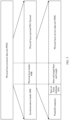
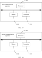
- FIG. 1 is a schematic diagram of an architecture of a wireless communication system according to an embodiment of this application.
- the wireless communication system uses a star topology structure.
- the star topology structure includes a central control device and one or more distribution devices. Communication transmission may be performed between the central control device and the one or more distribution devices.
- the network shown in FIG. 1 may be a WPAN, and the central control device may be a WPAN coordinator, that is, act as a coordinator in the WPAN.
- the central control device and the distribution device can sense a target in a surrounding environment, and obtain a corresponding sensing measurement result.
- the wireless communication system includes two types of devices: a full-function device (Full-Function Device) and a reduced-function device (Reduced-Function Device) respectively.
- FIG. 2 is a schematic diagram of another architecture of a wireless communication system according to an embodiment of this application.
- the wireless communication system uses a point-to-point topology structure.
- the network shown in FIG. 2 may be a WPAN, and a device a shown in FIG. 2 may serve as a WPAN coordinator, that is, act as a coordinator in the WPAN.
- WPAN coordinator that is, act as a coordinator in the WPAN.
- different devices in FIG. 2 can sense a target in a surrounding environment, and obtain a corresponding sensing measurement result.
- the wireless communication system includes two types of devices: a full-function device and a reduced-function device respectively.
- the wireless communication system to which this application is applicable includes a first device and a second device.
- the first device includes a communication server, a router, a switch, a bridge, a computer device, a terminal device, a PAN coordinator, and the like.
- the second device includes a communication server, a router, a switch, a bridge, a computer device, a terminal device, and the like.
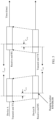
- a frame structure of a physical layer protocol data unit (PHY Protocol Data Unit, PPDU) in the UWB 802.15.4 standard is shown in FIG. 3 , and the PPDU includes a synchronization header (Synchronization Header, SHR), a physical layer header (PHY Header, PHR), and a physical layer payload (PHY Payload).
- PPDU Physical layer protocol Data Unit
- SHR Synchronization Header
- PHR physical layer header
- PHR physical layer payload
- the SHR includes a standard predefined preamble sequence (Preamble Sequence), and is used by a receive end device to perform PPDU detection and synchronization.
- the PHR carries some physical layer indication information, for example, modulation and coding information and a PPDU length, and is used to assist the receive end device in correctly demodulating data.
- the receive end device is a device that receives the PPDU.
- the receive end device may perform a correlation operation on a predefined preamble sequence and a preamble sequence in the PPDU (namely, a received signal), and determine, based on information such as a peak location in a result obtained through the correlation operation, arrival time at which the PPDU arrives at the receive end device.
- arrival time is time relative to a ranging marker (Ranging Marker, RMARKER), and the ranging marker herein is time at which a first pulse immediately following a start-of-frame delimiter (Start-of-Frame Delimiter, SFD) in the SHR arrives at a local antenna of the receive end device.
- a scrambled timestamp sequence (Scrambled Timestamp Sequence, STS) is introduced in the 802.15.4z standard.
- the STS is a pseudo-random sequence, and only a specific receive end device can learn of the STS.
- the receive end device performs a correlation operation on the STS and the PPDU (namely, the received signal), and estimates, based on the peak location in the correlation result obtained through the correlation operation, information of the arrival time at which the PPDU arrives at the receive end device.
- the PPDU includes an STS, and the STS may be placed before or after the PHY Payload, or may independently exist by replacing the PHY Payload. For example, as shown in FIG. 4(a) to FIG.
- the STS in FIG. 4(a) , the STS is before the PHR and the PHY Payload. In FIG. 4(b) , the STS is after the PHY Payload. In FIG. 4(c) , the PPDU includes the STS, but does not include the PHY Payload.
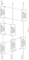
- the UWB wireless standard records a ranging procedure through an ultra-wideband signal. The following describes the ranging process.
- a device A sends a ranging PPDU to a device B, and records sending time of the ranging PPDU.
- the device B determines, based on a preamble sequence or an STS sequence in the ranging PPDU, arrival time at which the ranging PPDU arrives at the device B.
- the device B sends a response PPDU to the device A, and records sending time of the response PPDU.
- the device A determines arrival time of the response PPDU based on a preamble sequence or an STA sequence in the first response PPDU.
- the device A may determine round-trip time T round of this interaction based on the sending time of the ranging PPDU and the arrival time of the response PPDU.
- the device B may determine a reply time interval T reply based on the time of receiving the ranging PPDU and the time of sending the response PPDU. Therefore, transmission time T prop between the device A and the device B may be calculated according to the following Formula 1.
- T prop T round ⁇ T reply 2
- the device B may send the calculated reply time interval T reply to the device A.
- a distance between the device A and the device B is equal to the transmission time T prop multiplied by a speed of light c.
- the ranging process implements distance measurement between two devices.
- determining of arrival time of a line-of-sight signal is only concerned to determine the distance between the device A and the device B, and sensing of another target in a surrounding environment is not supported.
- this application provides corresponding technical solutions, to implement sensing of another target in a surrounding environment in a UWB wireless communication system and obtain a corresponding sensing measurement result.
- the sensing measurement result may alternatively be referred to as a channel impulse response (Channel Impulse Response, CIR) measurement result.
- CIR Channel Impulse Response
- a first device may perform sensing measurement with one or more second devices, and receive a sensing measurement result separately obtained by the one or more second devices. This is not specifically limited in this application.
- a sensing measurement process between the first device and the second device is used as an example to describe the technical solutions of this application.
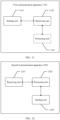
- FIG. 6 is a schematic diagram of an embodiment of a sensing measurement method according to an embodiment of this application. Refer to FIG. 6 .
- the sensing measurement method includes:
- a first device sends a first PPDU to a second device.
- the second device receives the first PPDU from the first device.
- the first PPDU is used for sensing measurement.
- the first PPDU includes a preamble sequence, where the preamble sequence is carried in an SHR field of the first PPDU.
- the preamble sequence is carried in an SHR field of the first PPDU.
- the first PPDU further includes an STS.
- the STS is carried in an STS field of the first PPDU.
- FIG. 4(a) to FIG. 4(c) refer to the schematic diagrams of the frame structures of the PPDU shown in FIG. 4(a) to FIG. 4(c) .
- a device A sends sensing PPDUs to a device B and a device C, so that the device B and the device C perform sensing measurement on the sensing PPDU.
- the technical solutions of this application are applicable to a UWB wireless communication system, and the first device and the second device may be two UWB devices in the UWB wireless communication system.
- the first PPDU may also be referred to as a sensing PPDU, and the two UWB devices perform sensing measurement on a surrounding environment by using the sensing PPDU.
- the embodiment shown in FIG. 6 further includes step 600a and step 600b. Step 600a and step 600b may be performed before step 601.
- the first device sends a sensing measurement request to the second device.
- the second device receives the sensing measurement request from the first device.
- the sensing measurement request is used to request the second device to assist the first device in performing sensing measurement.
- the second device sends a sensing measurement consent response to the first device.
- the first device receives the sensing measurement consent response from the second device.
- the sensing measurement consent response indicates that the second device agrees to assist the first device in performing sensing measurement.
- the device A may send sensing measurement requests to the device B and the device C. If the device B and the device C agree to assist the device A in performing sensing measurement, the device B and the device C separately feed back a sensing measurement consent response to the device A, to indicate that the device B and the device C agree to assist the device A in performing the sensing measurement.
- the second device feeds back sensing measurement rejection response, to indicate that the second device refuses to assist the first device in performing the sensing measurement.
- the first device cannot perform sensing measurement with the second device, and the first device may select another device to perform sensing measurement.
- the second device performs sensing measurement on the first PPDU, to obtain a sensing measurement result.
- the sensing measurement result includes at least one of the following: transmission path quantity information, multipath signal component amplitude information, time information, angle information, and location information of the second device.
- the second device may perform a correlation operation on a predefined preamble sequence or STS and the first PPDU.
- a correlation operation process if the second device determines the quantity of transmission paths between the first device and the second device based on a quantity of peak locations that appear in a correlation result, for example, in one sensing PPDU interaction process, the correlation result includes three peak locations, it indicates that there are three transmission paths between the first device and the second device.
- the multipath signal component amplitude information includes signal amplitude information corresponding to the first PPDU on the at least one transmission path.
- the multipath signal component amplitude information includes in-phase signal amplitude information and quadrature signal amplitude information.
- the in-phase signal amplitude information includes amplitude information of an in-phase signal corresponding to the first PPDU on the at least one transmission path.
- the quadrature signal amplitude information includes an amplitude signal of a quadrature signal corresponding to the first PPDU on the at least one transmission path.
- the second device determines amplitude information of an in-phase signal and amplitude information of a quadrature signal of the first PPDU transmitted on each transmission path, and carries the amplitude information of the in-phase signal and the amplitude information of the quadrature signal in the sensing measurement result.
- a signal amplitude of the first PPDU transmitted on each transmission path is indicated via the amplitude information of the in-phase signal and the amplitude information of the quadrature signal of the first PPDU transmitted on each transmission path.
- the second device may perform a correlation operation on a predefined preamble sequence and a preamble sequence in the first PPDU, to obtain a correlation result.
- the second device may perform a correlation operation on a locally determined STS and an STS in the first PPDU, to obtain a correlation result.
- the correlation result includes a peak location corresponding to each transmission path.
- An absolute value of the amplitude of the signal of the first PPDU is indicated as a 2 + b 2
- a phase of the signal of the first PPDU is indicated as ⁇ .
- the in-phase signal amplitude information includes at least one first amplitude difference, and the at least one first amplitude difference corresponds to the at least one transmission path.
- the at least one first amplitude difference one-to-one corresponds to the at least one transmission path, and each first amplitude difference corresponds to one transmission path.
- Each first amplitude difference is determined based on an amplitude of an in-phase signal of the first PPDU transmitted on a transmission path corresponding to the first amplitude difference and an amplitude of an in-phase signal of the first PPDU transmitted on a first transmission path.
- the first transmission path is a transmission path that is in the at least one transmission path and on which the first PPDU has strongest signal energy.
- each first amplitude difference is equal to a logarithm of a first ratio
- the first ratio is a ratio of the amplitude of the in-phase signal of the first PPDU transmitted on the transmission path corresponding to the first amplitude difference to the amplitude of the in-phase signal of the first PPDU transmitted on the first transmission path.
- the transmission path 1 is a line of sight between the device A and the device B.
- the transmission path 2 is a transmission path from the device A to a target 1 and then to the device B.
- the transmission path 3 is a transmission path from the device A to a target 2 and then to the device B.
- the target 1 and the target 2 may be understood as targets (for example, passive targets) in a surrounding environment of the device A and the device B.
- the device B measures signal energy of the first PPDU on each transmission path, and determines that signal energy of the first PPDU on the transmission path 1 is the largest. This is merely an example.
- a transmission path with largest signal energy may alternatively be another transmission path, and may not necessarily be the line of sight.
- the first PPDU transmitted on each transmission path includes two parts of signals: an in-phase (In-phase) signal and a quadrature (Quadrature) signal respectively.
- the second device may determine three first amplitude differences: D1, D2, and D3 respectively.
- D1 corresponds to the transmission path 1. Because the signal energy of the first PPDU on the transmission path 1 is the largest, D1 is equal to 0.
- D2 log 2 ( P ), where log 2 ( P ) means a logarithm of P, and P is a ratio of an amplitude of an in-phase signal of the first PPDU transmitted on the transmission path 2 to an amplitude of an in-phase signal of the first PPDU transmitted on the transmission path 1.
- D3 log 2 ( Q ), where log 2 ( Q ) means a logarithm of Q, and Q is a ratio of an amplitude of an in-phase signal of the first PPDU transmitted on the transmission path 3 to the amplitude of the in-phase signal of the first PPDU transmitted on the transmission path 1.
- the first transmission path is the transmission path that is in the at least one transmission path and on which the first PPDU has the strongest signal energy. In actual application, this is not limited in this application.
- the first transmission path may be any transmission path in the at least one transmission path.
- the first transmission path may alternatively be a transmission path that is in the at least one transmission path and on which the first PPDU has moderate signal energy.
- the quadrature signal amplitude information includes at least one second amplitude difference, and the at least one second amplitude difference corresponds to the at least one transmission path.
- the at least second amplitude difference one-to-one corresponds to the at least one transmission path, and each second amplitude difference corresponds to one transmission path.
- Each second amplitude difference is determined based on an amplitude of a quadrature signal of the first PPDU transmitted on a transmission path corresponding to the second amplitude difference and an amplitude of a quadrature signal of the first PPDU transmitted on the first transmission path.
- each second amplitude difference is equal to a logarithm of a second ratio
- the second ratio is a ratio of the amplitude of the quadrature signal of the first PPDU transmitted on the transmission path corresponding to the second amplitude difference to the amplitude of the quadrature signal of the first PPDU transmitted on the first transmission path.
- the transmission path 1 is a line of sight between the device A and the device B.
- the transmission path 2 is a transmission path from the device A to a target 1 and then to the device B.
- the transmission path 3 is a transmission path from the device A to a target 2 and then to the device B.
- the target 1 and the target 2 may be understood as targets (for example, passive targets) in a surrounding environment of the device A and the device B.
- the second device measures signal energy of the first PPDU on each transmission path, and determines that signal energy of the first PPDU on the transmission path 1 is the largest.
- the first PPDU transmitted on each transmission path includes two parts of signals: an in-phase signal and a quadrature signal respectively.
- the second device may determine three second amplitude differences: E1, E2, and E3 respectively.
- E1 corresponds to the transmission path 1. Because the signal energy of the first PPDU on the transmission path 1 is the largest, E1 is equal to 0.
- E2 log 2 ( R ), where log 2 ( R ) means a logarithm of R, and R is a ratio of an amplitude of a quadrature signal of the first PPDU transmitted on the transmission path 2 to an amplitude of a quadrature signal of the first PPDU transmitted on the transmission path 1.
- E3 log 2 ( S ), where log 2 ( S ) means a logarithm of S, and S is a ratio of an amplitude of a quadrature signal of the first PPDU transmitted on the transmission path 3 to the amplitude of the quadrature signal of the first PPDU transmitted on the transmission path 1.
- the second device indicates the signal amplitude and the signal phase of the first PPDU on each transmission path via the at least one first amplitude difference and the at least one second amplitude difference.
- the time information includes time information corresponding to the first PPDU on the at least one transmission path.
- the time information includes at least one delay difference, and the at least one delay difference corresponds to the at least one transmission path.
- one delay difference corresponds to one transmission path, that is, the at least one delay difference one-to-one corresponds to the at least one transmission path.
- Each delay difference is a time difference between arrival time at which the first PPDU transmitted on a transmission path corresponding to the delay difference arrives at the second device and arrival time at which the first PPDU transmitted on a second transmission path arrives at the second device.
- the second transmission path is a transmission path that is in the at least one transmission path and on which transmission time of the first PPDU is the shortest.
- transmission time of the first PPDU on each transmission path may be indicated by a time difference between arrival time at which the first PPDU on different transmission paths arrives at the second device.
- the transmission path 1 is the line of sight between the device A and the device B.
- the transmission path 2 is the transmission path from the device A to the target 1 and then to the device B.
- the transmission path 3 is the transmission path from the device A to the target 2 and then to the device B.
- the device B measures arrival time at which the first PPDU on each transmission path arrives at the device B.
- the device B may perform a correlation operation on a predefined preamble sequence and a preamble sequence included in the first PPDU on a transmission path, to obtain a correlation result, and a horizontal coordinate corresponding to a peak location in the correlation result is arrival time at which the first PPDU on the transmission path arrives at the device B.
- the device B may perform a correlation operation on an STS and an STS included in the first PPDU on a transmission path, to obtain a correlation result, and a horizontal coordinate corresponding to a peak location in the correlation result is arrival time at which the first PPDU on the transmission path arrives at the device B.
- the transmission path 1 is a transmission path on which the transmission time of the first PPDU is the shortest.
- the device B may determine three delay differences: F1, F2, and F3 respectively.
- F1 corresponds to the transmission path 1. Because the signal energy of the first PPDU on the transmission path 1 is the largest, F1 is equal to 0.
- F2 is equal to a time difference between arrival time at which the first PPDU transmitted on the transmission path 2 arrives at the device B and arrival time at which the first PPDU transmitted on the transmission path 1 arrives at the device B.
- F3 is equal to a time difference between arrival time at which the first PPDU transmitted on the transmission path 3 arrives at the device B and the arrival time at which the first PPDU transmitted on the transmission path 1 arrives at the device B.
- the angle information includes information about an angle at which the first PPDU arrives at the second device on the at least one transmission path.
- the angle information includes at least one angle of arrival, and the at least one angle of arrival corresponds to the at least one transmission path.
- Each angle of arrival is an angle of arrival at which the first PPDU transmitted on a transmission path corresponding to the angle of arrival arrives at the second device.
- a plurality of antennas are deployed on the second device, and the second device separately receives, through the plurality of antennas, the first PPDU transmitted on transmission paths.
- the second device may determine the angle of arrival based on a time difference between receiving time at which the plurality of antennas receive the first PPDU on the transmission paths.
- the time difference between the receiving time at which the plurality of antennas receive the first PPDU on the transmission paths may be determined based on a phase difference of signals of the first PPDU on the transmission paths that is received by the plurality of antennas.
- the angle information includes the angle of arrival at which the first PPDU on each transmission path arrives at the second device.
- the angle information may alternatively include an angle of arrival that is of each of the plurality of antennas and at which the first PPDU on each transmission path arrives at the second device. This is not specifically limited in this application, namely, the angle of arrival at which the first PPDU on each transmission path arrives at each antenna of the second device.
- the location information of the second device includes at least one of the following: longitude information of the second device, latitude information of the second device, and altitude information of the second device.
- the second device sends a second PPDU to the first device, where the second PPDU includes the sensing measurement result.
- the first device receives the second PPDU from the second device.
- the device B and the device C separately perform sensing measurement (also referred to as channel impulse response measurement) based on the sensing PPDU, to obtain a CIR result 1 and a CIR result 2.
- the device B sends CIR feedback 1 to the device A, where the CIR feedback 1 includes the CIR result 1.
- the device C sends CIR feedback 2 to the device A, where the CIR feedback 2 includes the CIR result 2.
- the second PPDU includes a channel measurement feedback element (The Channel Measurement Feedback Element), and the sensing measurement result is carried in the channel measurement feedback element.
- the Channel Measurement Feedback Element may be included in a physical layer payload of the second PPDU.
- the channel measurement feedback element includes at least one of the following fields: a multipath quantity field, a multipath amplitude field, a multipath delay field, a multipath signal angle of arrival field, and a device location information field.
- the transmission path quantity information is carried in the multipath quantity field
- the multipath signal component amplitude information is carried in the multipath amplitude field
- the time information is carried in the multipath delay field
- the multipath signal angle of arrival field is carried in the multipath signal angle of arrival field
- the location information of the second device is carried in the device location information field.
- Table 1 shows a specific format of the channel measurement feedback element and a possible example in which the channel measurement feedback element carries the sensing measurement result.
- Table 1 Subfield (Subfield) Size (Size) Meaning (Meaning) Element identifier (Element ID) 8 bits (bits) Indicate that a channel measurement feedback element carries a sensing measurement result.
- Length (Length) 8 bits Indicate a total length of a multipath quantity field, a multipath amplitude field, a multipath delay field, a multipath signal angle of arrival field, and a device location information field
- Multipath quantity field 8 bits Indicate a quantity N tap of measured transmission paths
- Table 1 shows fields included in the channel measurement feedback element, lengths of the fields, and meanings respectively indicated by the fields. It should be noted that bit sizes of the fields shown in Table 1 are merely examples. This is not specifically limited in this application. For example, an amplitude corresponding to each transmission path in Table 1 may occupy 10 bits, 11 bits, 12 bits, or the like. Bits occupied by a relative delay corresponding to each transmission path in the multipath delay field in Table 1 may be 6 bits, 7 bits, 9 bits, or the like. Bits occupied by an angle of arrival corresponding to each transmission path in the multipath signal angle of arrival field shown in Table 1 may be 6 bits, 7 bits, 9 bits, or the like.
- bits may indicate information included in the sensing measurement result, that is, bit lengths of the fields in the foregoing example may be different.
- a sequence of the fields included in the channel measurement feedback element is not limited, and Table 1 is merely an example.
- the channel measurement feedback element includes at least one of the following fields: a multipath quantity field, fields separately corresponding to at least one transmission path, and a device location information field.
- Table 2 shows a specific format of the channel measurement feedback element and another possible example in which the channel measurement feedback element carries the sensing measurement result.
- Table 2 Subfield (Subfield) Size (Size) Meaning (Meaning) Element identifier (Element ID) 8 bits (bits) Indicate that a channel measurement feedback element carries a sensing measurement result Length (Length) 8 bits Indicate a total length of subfields of the carried sensing measurement result
- Multipath quantity field 8 bits Indicate a quantity N tap of measured transmission paths Fields of a transmission path 1 Amplitude of the transmission path 1 (Amplitude of tap 1) 16 bits First eight bits indicate a first amplitude difference corresponding to the transmission path 1, and last eight bits indicate a second amplitude difference corresponding to the transmission path 1 Relative delay corresponding to the transmission path 1 (Relative delay of tap 1) 8 bits Indicate a delay difference corresponding to the transmission path 1 Angle of arrival corresponding to the transmission path 1 (AoA of tap 1) 8 bits Indicate the angle of arrival
- amplitude information, time information, and angle information corresponding to each transmission path are separately carried in fields corresponding to each transmission path.
- bit sizes of the fields shown in Table 2 are merely examples. This is not specifically limited in this application.
- an amplitude corresponding to each transmission path in Table 2 may occupy 10 bits, 12 bits, 14 bits, or the like.
- Bits occupied by a relative delay corresponding to each transmission path in Table 2 may be 6 bits, 7 bits, 9 bits, or the like.
- Bits occupied by an angle of arrival corresponding to each transmission path in Table 2 may be 6 bits, 7 bits, 9 bits, or the like.
- a sequence of the fields included in the channel measurement feedback element is not limited, and Table 2 is merely an example.
- step 603a the embodiment shown in FIG. 6 further includes step 603a, and step 603a may be performed before step 603.
- the first device sends a measurement report request to the second device.
- the second device receives the measurement report request from the first device.
- the measurement report request indicates the second device to feed back the sensing measurement result.
- the device B may send the CIR feedback 1 to the device A, and the device C may send the CIR feedback 2 to the device A.
- the first device determines, based on the content of the sensing measurement result, information such as a distance between a target in a surrounding environment and the first device and a location and a moving speed of the target in the surrounding environment.
- the sensing measurement result includes the transmission path quantity information.
- the device A may preliminarily determine a quantity of targets in the surrounding environment based on the transmission path quantity information.
- the transmission path quantity information indicates the three transmission paths, and the device A may preliminarily determine that there are two targets.
- the device A learns of a distance of the transmission path 1 (the line of sight) between the device A and the device B. Specifically, the distance may be obtained by using the ranging process described above.
- the device A determines, based on the time information, the time difference between the arrival time at which the first PPDU on the transmission path 2 arrives at the device B and the arrival time at which the first PPDU on the transmission path 1 arrives at the device B.
- the distance of the line of sight between the device A and the device B is known. Therefore, the device A may determine a distance of the transmission path 2 based on the distance and the time difference. Therefore, the device A may determine that a distance from the target 1 to the device A plus a distance from the target 1 to the device B equals the distance of the transmission path 2.
- the device A may determine, based on the angle information, an angle of arrival at which the first PPDU on the transmission path 2 arrives at the device B.
- the target 1 is located on the ellipse, and an angle ⁇ 1 between the target 1 and the device B may be approximately equal to the angle of arrival at which the first PPDU on the transmission path 2 arrives at the device B. Therefore, from the device B, an intersection point of the ellipse and a ray in a reverse direction of a direction of the angle of arrival is a location of the target 1.
- the device A may determine a distance L between the target 1 and the device B, and the device A may subtract the distance L between the target 1 and the device B from the distance of the transmission path 2, to obtain a distance K between the target 1 and the device A.
- a location of the device A is known, and the device A may determine, based on the distance K between the target 1 and the device A and the location of the device A, the location of the target 1.
- the process shown in FIG. 6 may be performed for a plurality of times.
- the device A may determine a moving speed of the target 1 based on the multipath signal component amplitude information reported for a plurality of times. Specifically, in a short period of time, an absolute value of an amplitude of a signal of the first PPDU on the transmission path 2 may be considered to be unchanged. However, due to the Doppler effect generated when the target 1 moves, a phase of the signal of the first PPDU on the transmission path 2 changes in measurement for a plurality of adjacent times. The device A may determine a phase change amount of the signal of the first PPDU on the transmission path 2 based on the multipath signal component amplitude information reported for the plurality of times.
- the device A obtains the Doppler frequency by dividing the phase change amount by measurement time of the measurement for the plurality of times. Then, the device A determines the moving speed of the target 1 based on the Doppler frequency and a wavelength of the signal of the first PPDU transmitted on the transmission path. A process of determining a distance between the target 2 and the device A and a location and a moving speed of the target 2 is also similar.
- the first device and the second device may be the two UWB devices in the UWB wireless communication system.
- the second device performs the channel impulse response measurement by using the preamble sequence or the STS in the first PPDU, and feeds back the multipath signal component amplitude information, the time information, the angle information, the transmission path quantity information, and the like that correspond to the at least one transmission path.
- the second device can perform the sensing measurement on the target (for example, the passive target) in the surrounding environment by using a UWB signal.
- the first device sends the first PPDU to the second device, where the first PPDU is used for the sensing measurement; and then the first device receives the second PPDU from the second device, where the second PPDU includes the sensing measurement result, and the sensing measurement result is obtained by the second device by performing the sensing measurement on the first PPDU.
- the first device receives the second PPDU from the second device, where the second PPDU includes the sensing measurement result, and the sensing measurement result is obtained by the second device by performing the sensing measurement on the first PPDU.
- the UWB device can sense the surrounding environment and feed back the corresponding sensing measurement result.
- FIG. 9 is a schematic diagram of another embodiment of a sensing measurement method according to an embodiment of this application. Refer to FIG. 9 .
- the sensing measurement method includes:
- a first device sends a trigger frame to a second device, where the trigger frame is used to trigger the second device to send the first PPDU.
- the second device receives the trigger frame from the first device.
- the first PPDU is used for sensing measurement.
- the trigger frame may also be referred to as a sensing measurement trigger frame
- the first PPDU may also be referred to as a sensing PPDU.
- the trigger frame includes first indication information, and the first indication information indicates a format of the first PPDU sent by the second device.
- the first indication information includes at least one of the following: an STS key, a signal time length, and a quantity of STS sequence repetitions.
- the STS key is used by the second device to generate an STS.
- the signal time length indicates a length of the STS.
- the quantity of STS sequence repetitions indicates a quantity of STS repetitions included in the first PPDU.
- the STS is repeatedly placed in the first PPDU, which helps the first device parse the STS.
- the second device may determine an STS by using the STS key, and perform a correlation operation on the determined STS and the STS in the first PPDU, to obtain a sensing measurement result. Therefore, security of the sensing measurement is improved.
- the second device sends the first PPDU to the first device.
- the first device receives the first PPDU from the second device.
- the second device sends the first PPDU in the format of the first PPDU that is indicated by the trigger frame in step 901.
- the first PPDU includes a preamble sequence and an STS.
- a length of the STS is a length indicated by the signal time length, and the STS is generated by using the STS key.
- a device A sends a sensing measurement trigger frame to a device B, to trigger the device B to send a sensing PPDU.
- the device B sends the sensing PPDU to the device Abased on the sensing measurement trigger frame.
- the technical solutions of this application are applicable to a UWB wireless communication system, and the first device and the second device may be two UWB devices in the UWB wireless communication system.
- the first PPDU may also be referred to as the sensing PPDU, and the two UWB devices perform sensing measurement on a surrounding environment by using the sensing PPDU.
- the first device performs sensing measurement on the first PPDU, to obtain a sensing measurement result.
- the first device performs the sensing measurement by using the preamble sequence or the STS in the first PPDU, to obtain the sensing measurement result.
- the first device may perform a correlation operation on a locally determined STS and the STS in the first PPDU to obtain a correlation result, and determine, based on a peak location of the correlation result, arrival time at which the first PPDU arrives at the first device, amplitude information of the first PPDU, and the like.
- the sensing measurement result includes at least one of the following: transmission path quantity information, multipath signal component amplitude information, time information, and angle information.
- the multipath signal component amplitude information includes in-phase signal amplitude information and quadrature signal amplitude information.
- the in-phase signal amplitude information includes amplitude information of an in-phase signal corresponding to the first PPDU on the at least one transmission path.
- the quadrature signal amplitude information includes an amplitude signal of a quadrature signal corresponding to the first PPDU on the at least one transmission path.
- the first device determines amplitude information of an in-phase signal and amplitude information of a quadrature signal of the first PPDU transmitted on each transmission path, and carries the amplitude information of the in-phase signal and the amplitude information of the quadrature signal in the sensing measurement result.
- a signal amplitude of the first PPDU transmitted on each transmission path is indicated via the amplitude information of the in-phase signal and the amplitude information of the quadrature signal of the first PPDU transmitted on each transmission path.
- the in-phase signal amplitude information includes at least one first amplitude difference, and the at least one first amplitude difference corresponds to the at least one transmission path.
- the at least one first amplitude difference one-to-one corresponds to the at least one transmission path, and each first amplitude difference corresponds to one transmission path.
- Each first amplitude difference is determined based on an amplitude of an in-phase signal of the first PPDU transmitted on a transmission path corresponding to the first amplitude difference and an amplitude of an in-phase signal of the first PPDU transmitted on a first transmission path.
- the first transmission path is a transmission path that is in the at least one transmission path and on which the first PPDU has strongest signal energy.
- each first amplitude difference is equal to a logarithm of a first ratio
- the first ratio is a ratio of the amplitude of the in-phase signal of the first PPDU transmitted on the transmission path corresponding to the first amplitude difference to the amplitude of the in-phase signal of the first PPDU transmitted on the first transmission path.
- the first amplitude difference refer to the related description in step 602 in the embodiment shown in FIG. 6 .
- the first transmission path is the transmission path that is in the at least one transmission path and on which the first PPDU has the strongest signal energy. In actual application, this is not limited in this application.
- the first transmission path may be any transmission path in the at least one transmission path.
- the first transmission path may alternatively be a transmission path that is in the at least one transmission path and on which the first PPDU has moderate signal energy.
- the quadrature signal amplitude information includes at least one second amplitude difference, and the at least one second amplitude difference corresponds to the at least one transmission path.
- the at least second amplitude difference one-to-one corresponds to the at least one transmission path, and each second amplitude difference corresponds to one transmission path.
- Each second amplitude difference is determined based on an amplitude of a quadrature signal of the first PPDU transmitted on a transmission path corresponding to the second amplitude difference and an amplitude of a quadrature signal of the first PPDU transmitted on the first transmission path.
- each second amplitude difference is equal to a logarithm of a second ratio
- the second ratio is a ratio of the amplitude of the quadrature signal of the first PPDU transmitted on the transmission path corresponding to the second amplitude difference to the amplitude of the quadrature signal of the first PPDU transmitted on the first transmission path.
- the second amplitude difference refer to the related description in step 602 in the embodiment shown in FIG. 6 .
- the time information includes time information corresponding to the first PPDU on the at least one transmission path.
- the time information includes at least one delay difference, and the at least one delay difference corresponds to the at least one transmission path.
- one delay difference corresponds to one transmission path, that is, the at least one delay difference one-to-one corresponds to the at least one transmission path.
- Each delay difference is a time difference between arrival time at which the first PPDU transmitted on a transmission path corresponding to the delay difference arrives at the first device and arrival time at which the first PPDU transmitted on a second transmission path arrives at the first device.
- the second transmission path is a transmission path that is in the at least one transmission path and on which transmission time of the first PPDU is the shortest.
- transmission time of the first PPDU on each transmission path may be indicated by a time difference between arrival time at which the first PPDU on different transmission paths arrives at the first device.
- the delay difference refer to the related description in step 602 in the embodiment shown in FIG. 6 .
- the angle information includes information about an angle at which the first PPDU arrives at the first device on the at least one transmission path.
- the angle information includes at least one angle of arrival, and the at least one angle of arrival corresponds to the at least one transmission path.
- Each angle of arrival is an angle of arrival at which the first PPDU transmitted on a transmission path corresponding to the angle of arrival arrives at the first device.
- a plurality of antennas are deployed on the first device, and the first device separately receives, through the plurality of antennas, the first PPDU transmitted on transmission paths.
- the first device may determine the angle of arrival based on a time difference between receiving time at which the plurality of antennas receive the first PPDU on the transmission paths.
- the angle information includes the angle of arrival at which the first PPDU on each transmission path arrives at the first device.
- the angle information may alternatively include an angle of arrival that is of each of the plurality of antennas and at which the first PPDU on each transmission path arrives at the first device. This is not specifically limited in this application, namely, the angle of arrival at which the first PPDU on each transmission path arrives at each antenna of the first device.
- the first device determines, based on the content included in the sensing measurement result, information such as a distance between a target in a surrounding environment and the first device and a moving speed of the target, refer to the related descriptions in step 603 in the embodiment shown in FIG. 6 . Details are not described herein again.
- the first device and the second device may be the two UWB devices in the UWB wireless communication system.
- the embodiment shown in FIG. 9 shows a process in which the first device initiates a sensing measurement trigger procedure, and performs the sensing measurement by using the sensing PPDU sent by the second device.
- the second device performs channel impulse response measurement by using the preamble sequence or the STS in the first PPDU to obtain the multipath signal component amplitude information, the time information, the angle information, the transmission path quantity information, and the like that correspond to the at least one transmission path between the first device and the second device.
- the first device can perform the sensing measurement on the target (for example, a passive target) in the surrounding environment by using a UWB signal, and there is no need to feed back the sensing measurement result.
- the first device sends the trigger frame to the second device, where the trigger frame is used to trigger the second device to send the first PPDU, and the first PPDU is used for the sensing measurement.
- the first device receives the first PPDU from the second device, and the first device performs the sensing measurement on the first PPDU, to obtain the sensing measurement result.
- the UWB device can sense a surrounding environment to obtain a corresponding sensing measurement result, and there is no need to feed back the sensing measurement result.
- FIG. 11 is a schematic diagram of a structure of a first communication apparatus according to an embodiment of this application.
- the first communication apparatus 1100 may be configured to perform the steps performed by the first device in the embodiment shown in FIG. 6 .
- the first communication apparatus 1100 may be configured to perform the steps performed by the first device in the embodiment shown in FIG. 6 .
- FIG. 6 For details, refer to the related descriptions in the embodiment shown in FIG. 6 .
- the first communication apparatus 1100 includes a sending unit 1101 and a receiving unit 1102.
- the first communication apparatus 1100 further includes a processing unit 1103.
- the sending unit 1101 is configured to perform a sending operation of the first device in the method embodiment shown in FIG. 6
- the receiving unit 1102 is configured to perform a receiving operation of the first device in the method embodiment shown in FIG. 6
- the processing unit 1103 is configured to perform a processing operation of the first device in the method embodiment shown in FIG. 6 .
- the first communication apparatus 1100 is configured to perform the following solution:
- the sending unit 1101 is configured to send a first PPDU to a second communication apparatus, where the first PPDU is used for sensing measurement; and the receiving unit 1102 is configured to receive a second PPDU from the second communication apparatus, where the second PPDU includes a sensing measurement result, and the sensing measurement result is obtained by the second communication apparatus by performing sensing measurement on the first PPDU.
- the sensing measurement result includes: transmission path quantity information, multipath signal component amplitude information, time information, angle information, and location information of the second communication apparatus.
- the transmission path quantity information indicates a quantity of transmission paths between the first communication apparatus 1100 and the second communication apparatus
- the multipath signal component amplitude information includes signal amplitude information corresponding to the first PPDU on at least one transmission path between the first communication apparatus 1100 and the second communication apparatus
- the time information includes time information corresponding to the first PPDU on the at least one transmission path
- the angle information includes information about an angle at which the first PPDU arrives at the second communication apparatus on the at least one transmission path.
- the multipath signal component amplitude information includes in-phase signal amplitude information and quadrature signal amplitude information
- the in-phase amplitude information includes amplitude information of an in-phase signal corresponding to the first PPDU on the at least one transmission path
- the quadrature amplitude information includes amplitude information of a quadrature signal corresponding to the first PPDU on the at least one transmission path.
- the in-phase signal amplitude information includes at least one first amplitude difference, the at least one first amplitude difference corresponds to the at least one transmission path, each first amplitude difference is determined based on an amplitude of an in-phase signal of the first PPDU transmitted on a transmission path corresponding to the first amplitude difference and an amplitude of an in-phase signal of the first PPDU transmitted on a first transmission path, and the first transmission path is a transmission path that is in the at least one transmission path and on which the first PPDU has strongest signal energy; and the quadrature signal amplitude information includes at least one second amplitude difference, the at least one second amplitude difference corresponds to the at least one transmission path, and each second amplitude difference is determined based on an amplitude of a quadrature signal of the first PPDU transmitted on a transmission path corresponding to the second amplitude difference and an amplitude of a quadrature signal of the first PPDU transmitted on the first transmission path.
- each first amplitude difference is equal to a logarithm of a first ratio
- the first ratio is a ratio of the amplitude of the in-phase signal of the first PPDU transmitted on the transmission path corresponding to the first amplitude difference to the amplitude of the in-phase signal of the first PPDU transmitted on the first transmission path
- each second amplitude difference is equal to a logarithm of a second ratio
- the second ratio is a ratio of the amplitude of the quadrature signal of the first PPDU transmitted on the transmission path corresponding to the second amplitude difference to the amplitude of the quadrature signal of the first PPDU transmitted on the first transmission path.
- the time information includes at least one delay difference
- the at least one delay difference corresponds to the at least one transmission path
- each delay difference is a time difference between arrival time at which the first PPDU transmitted on a transmission path corresponding to the delay difference arrives at the second communication apparatus and arrival time at which the first PPDU transmitted on a second transmission path arrives at the second communication apparatus
- the second transmission path is a transmission path that is in the at least one transmission path and on which transmission time of the first PPDU is the shortest.
- the angle information includes at least one angle of arrival, the at least one angle of arrival corresponds to the at least one transmission path, and each angle of arrival is an angle of arrival at which the first PPDU transmitted on a transmission path corresponding to the angle of arrival arrives at the second communication apparatus.
- the location information of the second communication apparatus includes at least one of the following: longitude information of the second communication apparatus, latitude information of the second communication apparatus, or altitude information of the second communication apparatus.
- the sending unit 1101 is further configured to:
- the sending unit 1101 is further configured to: send a measurement report request to the second communication apparatus, where the measurement report request is used to request the second communication apparatus to feed back the sensing measurement result.
- the second PPDU includes a channel measurement feedback element, and the sensing measurement result is carried in the channel measurement feedback element.
- the channel measurement feedback element includes at least one of the following fields: a multipath quantity field, a multipath amplitude field, a multipath delay field, a multipath signal angle of arrival field, and a device location information field, where the multipath quantity field is used to carry the transmission path quantity information, the multipath amplitude field is used to carry the multipath signal component amplitude information, the multipath delay field is used to carry the time information, the multipath signal angle of arrival field is used to carry the angle information, and the device location information field is used to carry the location information of the second communication apparatus.
- the multipath quantity field is used to carry the transmission path quantity information
- the multipath amplitude field is used to carry the multipath signal component amplitude information
- the multipath delay field is used to carry the time information
- the multipath signal angle of arrival field is used to carry the angle information
- the device location information field is used to carry the location information of the second communication apparatus.
- FIG. 12 is a schematic diagram of a structure of a second communication apparatus according to an embodiment of this application.
- the second communication apparatus 1200 may be configured to perform the steps performed by the second device in the embodiment shown in FIG. 6 .
- FIG. 6 For details, refer to the related descriptions in the embodiment shown in FIG. 6 .
- the second communication apparatus 1200 includes a receiving unit 1201, a processing unit 1202, and a sending unit 1203.
- the receiving unit 1202 is configured to perform a receiving operation of the second device in the method embodiment shown in FIG. 6
- the processing unit 1202 is configured to perform a processing operation of the second device in the method embodiment shown in FIG. 6
- the sending unit 1203 is configured to perform a sending operation of the second device in the method embodiment shown in FIG. 6 .
- the second communication apparatus 1200 is configured to perform the following solution:
- the receiving unit 1201 is configured to receive a first PPDU from a first communication apparatus
- the sensing measurement result includes: transmission path quantity information, multipath signal component amplitude information, time information, angle information, and location information of the second communication apparatus 1200.
- the transmission path quantity information indicates a quantity of transmission paths between the first communication apparatus and the second communication apparatus 1200
- the multipath signal component amplitude information includes signal amplitude information corresponding to the first PPDU on at least one transmission path between the first communication apparatus and the second communication apparatus 1200
- the time information includes time information corresponding to the first PPDU on the at least one transmission path
- the angle information includes information about an angle at which the first PPDU arrives at the second communication apparatus 1200 on the at least one transmission path.
- the multipath signal component amplitude information includes in-phase signal amplitude information and quadrature signal amplitude information
- the in-phase amplitude information includes amplitude information of an in-phase signal corresponding to the first PPDU on the at least one transmission path
- the quadrature amplitude information includes amplitude information of a quadrature signal corresponding to the first PPDU on the at least one transmission path.
- the in-phase signal amplitude information includes at least one first amplitude difference, the at least one first amplitude difference corresponds to the at least one transmission path, each first amplitude difference is determined based on an amplitude of an in-phase signal of the first PPDU transmitted on a transmission path corresponding to the first amplitude difference and an amplitude of an in-phase signal of the first PPDU transmitted on a first transmission path, and the first transmission path is a transmission path that is in the at least one transmission path and on which the first PPDU has strongest signal energy; and the quadrature signal amplitude information includes at least one second amplitude difference, the at least one second amplitude difference corresponds to the at least one transmission path, and each second amplitude difference is determined based on an amplitude of a quadrature signal of the first PPDU transmitted on a transmission path corresponding to the second amplitude difference and an amplitude of a quadrature signal of the first PPDU transmitted on the first transmission path.
- each first amplitude difference is equal to a logarithm of a first ratio
- the first ratio is a ratio of the amplitude of the in-phase signal of the first PPDU transmitted on the transmission path corresponding to the first amplitude difference to the amplitude of the in-phase signal of the first PPDU transmitted on the first transmission path
- each second amplitude difference is equal to a logarithm of a second ratio
- the second ratio is a ratio of the amplitude of the quadrature signal of the first PPDU transmitted on the transmission path corresponding to the second amplitude difference to the amplitude of the quadrature signal of the first PPDU transmitted on the first transmission path.
- the time information includes at least one delay difference
- the at least one delay difference corresponds to the at least one transmission path
- each delay difference is a time difference between arrival time at which the first PPDU transmitted on a transmission path corresponding to the delay difference arrives at the second communication apparatus 1200 and arrival time at which the first PPDU transmitted on a second transmission path arrives at the second communication apparatus 1200
- the second transmission path is a transmission path that is in the at least one transmission path and on which transmission time of the first PPDU is the shortest.
- the angle information includes at least one angle of arrival, the at least one angle of arrival corresponds to the at least one transmission path, and each angle of arrival is an angle of arrival at which the first PPDU transmitted on a transmission path corresponding to the angle of arrival arrives at the second communication apparatus 1200.
- the location information of the second communication apparatus 1200 includes at least one of the following: longitude information of the second communication apparatus 1200, latitude information of the second communication apparatus 1200, or altitude information of the second communication apparatus 1200.
- the receiving unit 1201 is further configured to:
- the receiving unit 1201 is further configured to: receive a measurement report request from the first communication apparatus, where the measurement report request is used to request the second communication apparatus 1200 to feed back the sensing measurement result.
- the second PPDU includes a channel measurement feedback element, and the sensing measurement result is carried in the channel measurement feedback element.
- the channel measurement feedback element includes at least one of the following fields: a multipath quantity field, a multipath amplitude field, a multipath delay field, a multipath signal angle of arrival field, and a device location information field, where the multipath quantity field is used to carry the transmission path quantity information, the multipath amplitude field is used to carry the multipath signal component amplitude information, the multipath delay field is used to carry the time information, the multipath signal angle of arrival field is used to carry the angle information, and the device location information field is used to carry the location information of the second communication apparatus 1200.
- the multipath quantity field is used to carry the transmission path quantity information
- the multipath amplitude field is used to carry the multipath signal component amplitude information
- the multipath delay field is used to carry the time information
- the multipath signal angle of arrival field is used to carry the angle information
- the device location information field is used to carry the location information of the second communication apparatus 1200.
- FIG. 13 is a schematic diagram of a structure of a first communication apparatus according to an embodiment of this application.
- the first communication apparatus 1300 may be configured to perform the steps performed by the first device in the embodiment shown in FIG. 9 .
- the first communication apparatus 1300 may be configured to perform the steps performed by the first device in the embodiment shown in FIG. 9 .
- FIG. 9 refers to the related descriptions in the embodiment shown in FIG. 9 .
- the first communication apparatus 1300 includes a sending unit 1301, a receiving unit 1303, and a processing unit 1303.
- the sending unit 1301 is configured to perform a sending operation of the first device in the method embodiment shown in FIG. 9
- the receiving unit 1302 is configured to perform a receiving operation of the first device in the method embodiment shown in FIG. 9
- the processing unit 1303 is configured to perform a processing operation of the first device in the method embodiment shown in FIG. 9 .
- the first communication apparatus 1300 is configured to perform the following solution:
- the trigger frame includes first indication information, and the first indication information indicates a format of the first PPDU sent by the second communication apparatus.
- the first indication information includes at least one of the following: an STS key, a signal time length, and a quantity of STS sequence repetitions.
- the sensing measurement result includes at least one of the following: transmission path quantity information, multipath signal component amplitude information, time information, and angle information.
- the transmission path quantity information indicates a quantity of transmission paths between the first communication apparatus 1300 and the second communication apparatus
- the multipath signal component amplitude information includes signal amplitude information corresponding to the first PPDU on at least one transmission path between the first communication apparatus 1300 and the second communication apparatus
- the time information includes time information corresponding to the first PPDU on the at least one transmission path
- the angle information includes information about an angle at which the first PPDU arrives at the first communication apparatus 1300 on the at least one transmission path.
- the multipath signal component amplitude information includes in-phase signal amplitude information and quadrature signal amplitude information
- the in-phase amplitude information includes amplitude information of an in-phase signal corresponding to the first PPDU on the at least one transmission path
- the quadrature amplitude information includes amplitude information of a quadrature signal corresponding to the first PPDU on the at least one transmission path.
- the in-phase signal amplitude information includes at least one first amplitude difference, the at least one first amplitude difference corresponds to the at least one transmission path, each first amplitude difference is determined based on an amplitude of an in-phase signal of the first PPDU transmitted on a transmission path corresponding to the first amplitude difference and an amplitude of an in-phase signal of the first PPDU transmitted on a first transmission path, and the first transmission path is a transmission path that is in the at least one transmission path and on which the first PPDU has a strongest signal capability; and the quadrature signal amplitude information includes at least one second amplitude difference, the at least one second amplitude difference corresponds to the at least one transmission path, and each second amplitude difference is determined based on an amplitude of a quadrature signal of the first PPDU transmitted on a transmission path corresponding to the second amplitude difference and an amplitude of a quadrature signal of the first PPDU transmitted on the first transmission path.
- each first amplitude difference is equal to a logarithm of a first ratio
- the first ratio is a ratio of the amplitude of the in-phase signal of the first PPDU transmitted on the transmission path corresponding to the first amplitude difference to the amplitude of the in-phase signal of the first PPDU transmitted on the first transmission path
- each second amplitude difference is equal to a logarithm of a second ratio
- the second ratio is a ratio of the amplitude of the quadrature signal of the first PPDU transmitted on the transmission path corresponding to the second amplitude difference to the amplitude of the quadrature signal of the first PPDU transmitted on the first transmission path.
- the time information includes at least one delay difference
- the at least one delay difference corresponds to the at least one transmission path
- each delay difference is a time difference between arrival time at which the first PPDU transmitted on a transmission path corresponding to the delay difference arrives at the first communication apparatus 1300 and arrival time at which the first PPDU transmitted on a second transmission path arrives at the first communication apparatus 1300
- the second transmission path is a transmission path that is in the at least one transmission path and on which transmission time of the first PPDU is the shortest.
- the angle information includes at least one angle of arrival, the at least one angle of arrival corresponds to the at least one transmission path, and each angle of arrival is an angle of arrival at which the first PPDU transmitted on a transmission path corresponding to the angle of arrival arrives at the first communication apparatus 1300.
- FIG. 14 is a schematic diagram of a structure of a second communication apparatus according to an embodiment of this application.
- the second communication apparatus 1400 may be configured to perform the steps performed by the second device in the embodiment shown in FIG. 9 .
- FIG. 9 refers to the related descriptions in the embodiment shown in FIG. 9 .
- the second communication apparatus 1400 includes a receiving unit 1401 and a sending unit 1402.
- the second communication apparatus 1400 further includes a processing unit 1403.
- the receiving unit 1401 is configured to perform a receiving operation of the second device in the method embodiment shown in FIG. 9
- the sending unit 1402 is configured to perform a sending operation of the second device in the method embodiment shown in FIG. 9 .
- the second communication apparatus 1400 is configured to perform the following solution:
- the trigger frame includes first indication information, and the first indication information indicates a format of the first PPDU sent by the second communication apparatus 1400.
- the first indication information includes at least one of the following: an STS key, a signal time length, and a quantity of STS sequence repetitions.
- the sensing measurement result includes at least one of the following: transmission path quantity information, multipath signal component amplitude information, time information, and angle information.
- the transmission path quantity information indicates a quantity of transmission paths between the first communication apparatus and the second communication apparatus 1400
- the multipath signal component amplitude information includes signal amplitude information corresponding to the first PPDU on at least one transmission path between the first communication apparatus and the second communication apparatus 1400
- the time information includes time information corresponding to the first PPDU on the at least one transmission path
- the angle information includes information about an angle at which the first PPDU arrives at the first communication apparatus on the at least one transmission path.
- the multipath signal component amplitude information includes in-phase signal amplitude information and quadrature signal amplitude information
- the in-phase amplitude information includes amplitude information of an in-phase signal corresponding to the first PPDU on the at least one transmission path
- the quadrature amplitude information includes amplitude information of a quadrature signal corresponding to the first PPDU on the at least one transmission path.
- the in-phase signal amplitude information includes at least one first amplitude difference, the at least one first amplitude difference corresponds to the at least one transmission path, each first amplitude difference is determined based on an amplitude of an in-phase signal of the first PPDU transmitted on a transmission path corresponding to the first amplitude difference and an amplitude of an in-phase signal of the first PPDU transmitted on a first transmission path, and the first transmission path is a transmission path that is in the at least one transmission path and on which the first PPDU has a strongest signal capability; and the quadrature signal amplitude information includes at least one second amplitude difference, the at least one second amplitude difference corresponds to the at least one transmission path, and each second amplitude difference is determined based on an amplitude of a quadrature signal of the first PPDU transmitted on a transmission path corresponding to the second amplitude difference and an amplitude of a quadrature signal of the first PPDU transmitted on the first transmission path.
- each first amplitude difference is equal to a logarithm of a first ratio
- the first ratio is a ratio of the amplitude of the in-phase signal of the first PPDU transmitted on the transmission path corresponding to the first amplitude difference to the amplitude of the in-phase signal of the first PPDU transmitted on the first transmission path
- each second amplitude difference is equal to a logarithm of a second ratio
- the second ratio is a ratio of the amplitude of the quadrature signal of the first PPDU transmitted on the transmission path corresponding to the second amplitude difference to the amplitude of the quadrature signal of the first PPDU transmitted on the first transmission path.
- the time information includes at least one delay difference
- the at least one delay difference corresponds to the at least one transmission path
- each delay difference is a time difference between arrival time at which the first PPDU transmitted on a transmission path corresponding to the delay difference arrives at the first communication apparatus and arrival time at which the first PPDU transmitted on a second transmission path arrives at the first communication apparatus
- the second transmission path is a transmission path that is in the at least one transmission path and on which transmission time of the first PPDU is the shortest.
- the angle information includes at least one angle of arrival, the at least one angle of arrival corresponds to the at least one transmission path, and each angle of arrival is an angle of arrival at which the first PPDU transmitted on a transmission path corresponding to the angle of arrival arrives at the first communication apparatus.
- FIG. 15 is a schematic diagram of another structure of the first communication apparatus according to this embodiment of this application.
- the first communication apparatus may be configured to perform the steps performed by the first device in the embodiments shown in FIG. 6 and FIG. 9 .
- FIG. 6 and FIG. 9 For details, refer to the related descriptions in the foregoing method embodiments.
- the first communication apparatus includes a processor 1501.
- the first communication apparatus further includes a memory 1502 and a transceiver 1503.
- the processor 1501, the memory 1502, and the transceiver 1503 are separately connected through a bus, and the memory stores computer instructions.
- the sending unit 1101 and the receiving unit 1102 shown in FIG. 11 may be specifically the transceiver 1503. Therefore, specific implementation of the transceiver 1503 is not described again.
- the processing unit 1103 shown in FIG. 11 may be specifically the processor 1501. Therefore, specific implementation of the processor 1501 is not described again.
- the sending unit 1301 and the receiving unit 1302 shown in FIG. 13 may be specifically the transceiver 1503. Therefore, specific implementation of the transceiver 1503 is not described again.
- the processing unit 1303 shown in FIG. 11 may be specifically the processor 1501. Therefore, specific implementation of the processor 1501 is not described again.
- FIG. 16 is a schematic diagram of another structure of the second communication apparatus according to this embodiment of this application.
- the second communication apparatus may be configured to perform the steps performed by the second device in the embodiments shown in FIG. 6 and FIG. 9 .
- FIG. 6 and FIG. 9 For details, refer to the related descriptions in the foregoing method embodiments.
- the second communication apparatus includes a processor 1601.
- the second communication apparatus further includes a memory 1602 and a transceiver 1603.
- the processor 1601, the memory 1602, and the transceiver 1603 are separately connected through a bus, and the memory stores computer instructions.
- the receiving unit 1201 and the sending unit 1203 shown in FIG. 12 may be specifically the transceiver 1603. Therefore, specific implementation of the transceiver 1603 is not described again.
- the processing unit 1202 shown in FIG. 12 may be specifically the processor 1601. Therefore, specific implementation of the processor 1601 is not described again.
- the receiving unit 1401 and the sending unit 1402 shown in FIG. 14 may be specifically the transceiver 1603. Therefore, specific implementation of the transceiver 1603 is not described again.
- the processing unit 1402 shown in FIG. 14 may be specifically the processor 1601. Therefore, specific implementation of the processor 1601 is not described again.
- the communication system includes a first device and a second device.
- the first device is configured to perform the steps performed by the first device in the embodiments shown in FIG. 6 and FIG. 9
- the second device is configured to perform the steps performed by the second device in the embodiments shown in FIG. 6 and FIG. 9 .
- An embodiment of this application provides a computer program product including instructions.
- the computer program product runs on a computer, any implementation in the embodiments shown in FIG. 6 and FIG. 9 is performed.
- An embodiment of this application provides a computer-readable storage medium, including computer instructions. When the instructions are run on a computer, any implementation in the embodiments shown in FIG. 6 and FIG. 9 is performed.
- An embodiment of this application provides a chip apparatus, including a processor, configured to invoke a computer program or computer instructions in a memory, so that any implementation in the embodiments shown in FIG. 6 and FIG. 9 is performed.
- the chip apparatus further includes a memory, and the memory is configured to store a computer degree, computer instructions, or the like.
- the chip apparatus may include a chip or may include a chip and another discrete component.
- the processor is coupled to the memory through an interface.
- the disclosed system, apparatus, and method may be implemented in other manners.
- the described apparatus embodiments are merely examples.
- division into the units is merely logical function division and may be other division in an actual implementation.
- a plurality of units or components may be combined or integrated into another system, or some features may be ignored or not performed.
- the displayed or discussed mutual couplings or direct couplings or communication connections may be implemented through some interfaces.
- the indirect couplings or communication connections between the apparatuses or units may be implemented in electronic, mechanical, or other forms.
- the units described as separate components may or may not be physically separate, and components displayed as units may or may not be physical units, may be located in one position, or may be distributed on a plurality of network units. Some or all of the units may be selected based on actual requirements to achieve the objectives of the solutions of embodiments.
- each of the units may exist alone physically, or two or more units may be integrated into one unit.
- the integrated unit may be implemented in a form of hardware, or may be implemented in a form of a software functional unit.
- the integrated unit When the integrated unit is implemented in the form of a software functional unit and sold or used as an independent product, the integrated unit may be stored in a computer-readable storage medium. Based on such an understanding, the technical solutions of this application essentially, or the part contributing to the conventional technology, or all or some of the technical solutions may be implemented in a form of a software product.
- the computer software product is stored in a storage medium, and includes several instructions for instructing a computer device (which may be a personal computer, a server, or a network device) to perform all or some of the steps of the methods described in embodiments of this application.
- the storage medium includes any medium that can store program code, such as a USB flash drive, a removable hard disk, a read-only memory (Read-Only Memory, ROM), a random access memory (Random Access Memory, RAM), a magnetic disk, or an optical disc.
- program code such as a USB flash drive, a removable hard disk, a read-only memory (Read-Only Memory, ROM), a random access memory (Random Access Memory, RAM), a magnetic disk, or an optical disc.
Landscapes
- Engineering & Computer Science (AREA)
- Computer Networks & Wireless Communication (AREA)
- Signal Processing (AREA)
- Physics & Mathematics (AREA)
- Electromagnetism (AREA)
- Power Engineering (AREA)
- Quality & Reliability (AREA)
- Mobile Radio Communication Systems (AREA)
Applications Claiming Priority (2)
| Application Number | Priority Date | Filing Date | Title |
|---|---|---|---|
| CN202111277365.5A CN116074884A (zh) | 2021-10-29 | 2021-10-29 | 感知测量方法以及相关装置 |
| PCT/CN2022/127611 WO2023072130A1 (zh) | 2021-10-29 | 2022-10-26 | 感知测量方法以及相关装置 |
Publications (2)
| Publication Number | Publication Date |
|---|---|
| EP4412296A1 true EP4412296A1 (de) | 2024-08-07 |
| EP4412296A4 EP4412296A4 (de) | 2025-01-29 |
Family
ID=86160474
Family Applications (1)
| Application Number | Title | Priority Date | Filing Date |
|---|---|---|---|
| EP22886006.0A Pending EP4412296A4 (de) | 2021-10-29 | 2022-10-26 | Messmessverfahren und zugehörige vorrichtung |
Country Status (3)
| Country | Link |
|---|---|
| EP (1) | EP4412296A4 (de) |
| CN (1) | CN116074884A (de) |
| WO (1) | WO2023072130A1 (de) |
Families Citing this family (6)
| Publication number | Priority date | Publication date | Assignee | Title |
|---|---|---|---|---|
| US20230216804A1 (en) * | 2022-01-04 | 2023-07-06 | Vmware, Inc. | Efficient mechanism for the transmission of multipath duplicate packets |
| CN118945703A (zh) * | 2023-05-12 | 2024-11-12 | 华为技术有限公司 | 感知测量方法及装置 |
| CN119450718A (zh) * | 2023-08-07 | 2025-02-14 | 华为技术有限公司 | 感知通信方法及装置 |
| CN119497074A (zh) * | 2023-08-16 | 2025-02-21 | 华为技术有限公司 | 感知通信方法及装置 |
| CN119907029B (zh) * | 2023-09-07 | 2025-11-25 | 华为技术有限公司 | Uwb系统中的信息交互方法及装置 |
| CN120779381A (zh) * | 2024-04-01 | 2025-10-14 | 华为技术有限公司 | 基于感知包的感知或测距方法、装置及可读存储介质 |
Family Cites Families (5)
| Publication number | Priority date | Publication date | Assignee | Title |
|---|---|---|---|---|
| US10200147B2 (en) * | 2016-04-05 | 2019-02-05 | Intel IP Corporation | Sending feedback in a high efficiency service field |
| WO2018195174A1 (en) * | 2017-04-19 | 2018-10-25 | Feng Jiang | Measurement report for a measurement protocol |
| US10999110B2 (en) * | 2017-07-07 | 2021-05-04 | Qualcomm Incorporated | Techniques for selecting PPDU format parameters |
| US11075778B2 (en) * | 2019-09-26 | 2021-07-27 | Intel Corporation | Apparatus, system and method of wireless sensing |
| JP7366792B2 (ja) * | 2020-02-14 | 2023-10-23 | 株式会社東海理化電機製作所 | 通信装置、情報処理方法、及びプログラム |
-
2021
- 2021-10-29 CN CN202111277365.5A patent/CN116074884A/zh active Pending
-
2022
- 2022-10-26 WO PCT/CN2022/127611 patent/WO2023072130A1/zh not_active Ceased
- 2022-10-26 EP EP22886006.0A patent/EP4412296A4/de active Pending
Also Published As
| Publication number | Publication date |
|---|---|
| CN116074884A (zh) | 2023-05-05 |
| EP4412296A4 (de) | 2025-01-29 |
| WO2023072130A1 (zh) | 2023-05-04 |
Similar Documents
| Publication | Publication Date | Title |
|---|---|---|
| EP4412296A1 (de) | Messmessverfahren und zugehörige vorrichtung | |
| US20240430845A1 (en) | Method and device for user equipment positioning | |
| US20240023078A1 (en) | Communication method and communication apparatus | |
| JP7263590B2 (ja) | 情報指示方法、装置、プログラム、及びコンピュータ可読記憶媒体 | |
| EP2244098B1 (de) | Master-Sende-Empfangsgerät und Slave-Sende-Empfangsgerät zur Bestimmung von Bereichsinformation | |
| US12326495B2 (en) | Object locating method and apparatus | |
| CN111586831A (zh) | 信号传输方法与装置 | |
| EP4387356A1 (de) | Uwb-kommunikationsverfahren, kommunikationsvorrichtung und system | |
| US20250047527A1 (en) | Method for feeding back sensing measurement result based on ultra wideband and apparatus | |
| US20250106078A1 (en) | Information Interaction Method and Related Apparatus | |
| US20250097820A1 (en) | Data transmission method and apparatus | |
| US12457079B2 (en) | Information indication method and apparatus | |
| EP3609255B1 (de) | Signalverarbeitungsverfahren und -vorrichtung | |
| Neuhold et al. | HiPR: High-precision UWB ranging for sensor networks | |
| US20250142547A1 (en) | Method for wireless communication and device | |
| US20250105967A1 (en) | Uwb-based ppdu transmission method and related apparatus | |
| EP4604405A1 (de) | Messbasiertes kommunikationsverfahren und vorrichtung | |
| EP4564693A1 (de) | Informationsanzeigeverfahren und -vorrichtung sowie kommunikationsvorrichtung | |
| EP4661436A1 (de) | Kommunikationserfassungsverfahren und -vorrichtung | |
| WO2025213433A1 (en) | Methods, apparatuses and systems for joint passive target and active node positioning | |
| EP4489324A1 (de) | Signalverarbeitungsverfahren und kommunikationsvorrichtung | |
| WO2025051098A1 (zh) | 一种测量方法及装置 | |
| Blanco Pizarro | Algorithms for robust indoor localization and sensing using off-the-shelf devices using off-the-shelf devices | |
| WO2024250910A1 (zh) | 相位确定方法及装置 | |
| TW202444129A (zh) | 基於頻帶拼接的ppdu傳輸方法及裝置 |
Legal Events
| Date | Code | Title | Description |
|---|---|---|---|
| STAA | Information on the status of an ep patent application or granted ep patent |
Free format text: STATUS: THE INTERNATIONAL PUBLICATION HAS BEEN MADE |
|
| PUAI | Public reference made under article 153(3) epc to a published international application that has entered the european phase |
Free format text: ORIGINAL CODE: 0009012 |
|
| STAA | Information on the status of an ep patent application or granted ep patent |
Free format text: STATUS: REQUEST FOR EXAMINATION WAS MADE |
|
| 17P | Request for examination filed |
Effective date: 20240430 |
|
| AK | Designated contracting states |
Kind code of ref document: A1 Designated state(s): AL AT BE BG CH CY CZ DE DK EE ES FI FR GB GR HR HU IE IS IT LI LT LU LV MC ME MK MT NL NO PL PT RO RS SE SI SK SM TR |
|
| A4 | Supplementary search report drawn up and despatched |
Effective date: 20250107 |
|
| RIC1 | Information provided on ipc code assigned before grant |
Ipc: H04L 25/02 20060101ALI20241220BHEP Ipc: H04B 17/364 20150101ALI20241220BHEP Ipc: H04B 17/318 20150101ALI20241220BHEP Ipc: H04B 17/00 20150101ALI20241220BHEP Ipc: H04W 24/10 20090101AFI20241220BHEP |
|
| DAV | Request for validation of the european patent (deleted) | ||
| DAX | Request for extension of the european patent (deleted) |